EP2182823B1 - Rastelement-justagesystem für fahrradschuhe - Google Patents
Rastelement-justagesystem für fahrradschuhe Download PDFInfo
- Publication number
- EP2182823B1 EP2182823B1 EP08787422A EP08787422A EP2182823B1 EP 2182823 B1 EP2182823 B1 EP 2182823B1 EP 08787422 A EP08787422 A EP 08787422A EP 08787422 A EP08787422 A EP 08787422A EP 2182823 B1 EP2182823 B1 EP 2182823B1
- Authority
- EP
- European Patent Office
- Prior art keywords
- locking element
- shoe
- adjustment system
- locking
- base
- Prior art date
- Legal status (The legal status is an assumption and is not a legal conclusion. Google has not performed a legal analysis and makes no representation as to the accuracy of the status listed.)
- Active
Links
Images


Classifications
-
- A—HUMAN NECESSITIES
- A43—FOOTWEAR
- A43B—CHARACTERISTIC FEATURES OF FOOTWEAR; PARTS OF FOOTWEAR
- A43B5/00—Footwear for sporting purposes
- A43B5/14—Shoes for cyclists
Definitions
- the invention relates to a locking element adjustment system for bicycle shoes.
- Cycling shoes which are used in particular in conjunction with mountain bike, road bike and triathlon pedals, have a fastening system for attaching or clicking on the shoe on the pedal.
- a well-known click system which is particularly used in mountain bike shoes, comes from the company. Shimano Inc. and is and is sold under the name SPD.
- the locking elements to be connected to the sole of the bicycle shoe which are often referred to as cleats, must be adjusted as accurately as possible.
- the attachment of the locking elements is usually carried out by means of two screws.
- the screws are inserted through slots provided in the shoe sole and engage in a provided on the shoe inner side threaded plate. Since long holes are formed in the shoe sole in the longitudinal direction of the shoe, the locking elements can be adjusted in the longitudinal direction.
- the locking element itself has in the area in which the screws are passed and the screw heads are received, also formed as slots holes. The orientation of these slots is transverse to the shoe longitudinal direction. This can be done with respect to the shoe lateral displacement or alignment of the locking element.
- the position of the locking elements on both shoes should be as equal as possible. This is done today in that the user looks at the shoes from below and adjusts the position of the locking elements by eye. This often leads to incorrect settings, since the shoe sole is often offset laterally with respect to the upper shoe. This has the result that even a precisely identical arrangement of the locking elements on the shoe sole does not ensure that the locking element is arranged in relation to the foot of the user in the same position.
- WO 2005/025974 is a gattungsires locking element adjustment system for cycling shoes known. This has a base plate on which the bicycle shoe is fixed with retaining elements, so that the bicycle shoe is displaceable relative to the base plate neither in the longitudinal direction nor transversely to the longitudinal direction.
- the locking element is arranged in a pivotable holder.
- the holder is pivotally connected to the base plate. By pivoting the holder, a previously known inclination angle of the locking element can be adjusted relative to the longitudinal axis of the shoe.
- the object of the invention is to provide a locking element adjustment system for bicycle shoes and a corresponding method, can be adjusted with the simple way locking elements for bicycle shoes,
- the locking element adjustment system according to the invention for bicycle shoes has a base element and a receiving element connected to the base element.
- the receiving element serves to receive the latching element or cleats to be accurately aligned with the bicycle shoe.
- the receiving element is designed such that, with the aid of the receiving element, first of all a defined, positionally accurate receptacle with respect to the base element can take place. This can be done, for example, that the base member has a mark on which the receiving element is connected, for example, by gluing to the base member.
- the base element has adjustment elements. These may be markings for the lateral distance of the locking element to the pedal crank, for the angular position of the heel of the shoe, for the alignment of the cleats in the longitudinal direction or relative to the pedal axis, etc.
- the adjustment elements according to the invention on several arranged at different distances from the receiving element crank lines, which indicate the distance between the receiving element and crank.
- the receiving element may be connected to the base element, for example by gluing, by fixing or the like.
- the base element can also be integrally formed with the receiving element, for example made of plastic.
- the receiving element for receiving the cleat is a component independent of the base element.
- the shoe to which the cleat is to be mounted can first be aligned with regard to the base element or with regard to adjustment elements provided on the base element and can be fixed in this position, for example, via retaining elements. Subsequently, the exact position of the receiving element relative to the shoe can be done by moving and / or rotating the receiving element.
- the receiving element with a holding element, such as a rod to be connected, the holding member preferably protrudes laterally over the Base element, so that the receiving element can be moved by the holding element, while the base member is viewed, for example, with shoe arranged thereon from above.
- the base member may include a guide member in which the holding member is held and guided, for example.
- the guide element serves to ensure that the holding element always rests against an underside of the base element, since in the case of a flat base element only displacement of the cleat in one plane is necessary. Perpendicular to this plane or perpendicular to the shoe sole shifting the cleats is not required.
- the latching element can thus initially be brought to the base element in a defined position.
- the provided on the base element adjustment elements which may be markings such as lines, angles and the like, it is then possible to adjust the exact position of the locking element relative to the bicycle shoe.
- the position of a locking element can be transferred from one shoe to another shoe using the adjustment system in a simple manner. This has the advantage that the locking elements actually have the same position on both shoes. It is also possible, for example, to initially determine the position of the latching element to be exchanged when replacing latching elements and then to fasten the new latching element at the exact same point of the shoe.
- the receiving element preferably has lugs that allow, for example, a positive reception.
- the example pin-shaped projections are preferably arranged such that the reception of the locking element takes place between the lugs, wherein preferably at least three lugs are provided, against which the latching element bears.
- the lugs are therefore preferably arranged on an outer contour line of the latching element.
- the shape or contour of the lugs corresponds at least partially to a part of the outer contour of the latching element.
- the individual projections are thus formed corresponding to a wall whose shape at least partially corresponds to a part of the outer contour line.
- a single approach or a wall element which surrounds the latching element.
- the shape or contour of the wall element at least partially corresponds to the outer contour line of the latching element.
- the individual lugs or the wall elements are designed such that latching elements of different manufacturers are precise position, in particular form-fitting, received by the receiving element and thus arranged exactly with respect to the base member.
- the receiving element has a passage opening in order, for example, to be able to put on the shoe sole resting latching element adjustment system, the fastening screws of the locking elements.
- the entire receiving element is formed as a passage opening or at least one passage opening is provided, which releases the screws.
- the base member is a flat plate which is at least partially transparent. It is particularly preferred to form the base element in one piece together with the receiving element, wherein preferably plastic is used.
- the adjustment elements preferably imprinted directly on the base member, embossed etc. markings, which are preferably lines.
- the lines may be labeled with numbers referring to certain types of pedals, numbers or letters.
- the adjustment elements comprise a pedal line through which the pedal axle is depicted.
- a longitudinal symmetry line can be provided as a further adjustment element.
- the longitudinal symmetry line is an extension of the symmetry line of the latching element.
- the longitudinal symmetry line is preferably projecting beyond the heel element of the bicycle shoe, so that the longitudinal symmetry line is visible from above when viewing the bicycle shoe standing on a detent element adjustment system.
- the adjustment elements may have crank lines. These are lines that are arranged parallel to the longitudinal symmetry line at a distance from the receiving element and illustrate the distance between the receiving element and crank.
- the crank lines may be provided with the name of pedal types, since essentially by the pedal type, the distance between the locking element recording of the pedal and the crank, and thus between the locking element and the pedal crank is defined.
- transmission lines or transmission markings can be provided on the base element as adjustment elements. These serve to transfer the position of a locking element on the other shoe, or to attach the new locking element in the exact same position as the old locking element on the shoe when replacing locking elements.
- the receiving element for receiving the latching element has the outer contour of a latching element of commercially available latching elements or cleats. These are in particular cleats of the company Shimano with the name "SPD" as well as cleats of the company Look.
- the base element is in particular flat and has a size such that the entire shoe rests on the base element.
- the base element preferably made of plastic, is hollow in a particularly preferred embodiment, at least in the region of the heel elevation. As a result, a compartment can be formed in which a handling instruction or the like can be accommodated.
- a separate base element is provided in each case for the left and the right shoe. These may be interconnected or integrally formed. It is preferred here that the two base elements are hinged together, so that the storage space is low. The connection can take place via a film hinge or the like.
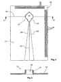
- the receiving element for the positionally accurate arrangement of a latching element 14 (FIG. Fig. 3 ), a wall member 16 which completely surrounds the locking element 14.
- the wall element 16 has a contour that corresponds to the outer contour of the latching element 14, so that the latching element 14 in an opening 18 (FIG. Fig. 1 ) of the receiving element 12 is received positively.
- the opening 18 is formed as a passage opening, wherein the size of the opening of the base surface of the locking element corresponds, so that the locking element could be inserted through the opening 18. Possibly. are parts of the opening 18, in particular in areas where no fastening screws 20 (FIG. Fig. 3 ) are provided, closed in order to insert the locking element in the base member 10 and to avoid falling out or slipping of the locking element 14.
- adjustment elements are arranged on an upper side 22 of the base member 1. These are marks that are printed, for example.
- An adjustment element consists of a pedal line 24.
- the pedal line marks the pedal axle. It is thus the central axis of the pedal around which the pedal is turned. About this axis, the force is transmitted when pedaling on the pedal.
- a further adjustment element consists in the longitudinal axis of symmetry 26. This is the longitudinal axis of symmetry of the latching element or its extension shown on the upper side 22 of the base element 10.
- two heel lines 28 are fan-shaped in the illustrated embodiment, which for adjusting the pivoting of the heel element 30 (FIG. Fig. 4 ) of the bicycle shoe 32 is used.
- crank lines 34 are provided with numbers or letters. If necessary, the numbers or letters can be assigned to pedal types, since the distance between the locking element and the crank arm is essentially defined by the type of pedal. Also, the individual pedestrian types of interest may be imprinted directly on the surface 22 of the base member 10.
- transmission lines 38 are preferably provided with numbers ( Fig. 4 ).
- a first step one of the two shoes is tightened by the user and the big toe joint on the inside of the shoe is felt.
- the position of the big toe joint is then marked on the shoe, for example with chalk, a sticker or the like.
- the locking element is loosely connected to the sole 40 of the shoe 32 by usually on the inside of the shoe, a plate is arranged with threads into which screws 20 are screwed for fixing the locking element.
- the screws 20 are initially not tightened.
- the locking element is inserted into the opening 18, in particular from the bottom view of Fig. 3 seen.
- the shoe 32 is now in the direction of arrow 42 ( Fig. 4 ) until the mark of the big toe joint is aligned with the pedal line 24. This ensures that there is good power transmission to the pedal and the pedal axle on the pedal.
- crank lines 34 are used for this purpose. Either the crank lines are marked pedal-specific, so that alignment of the shoe in the direction of an arrow 44 (FIG. Fig. 4 ) can be done easily.
- the base member 10 on the pedal such that the locking element receptacle of the pedal is disposed within the opening 18, and by pointing along the crank the corresponding crank line 34th be determined. There is now a shift of the shoe in the direction of arrow 44 ( Fig. 4 ).
- the heel angle i. the rotation of the heel element 30 of the shoe 32 is essentially dependent on the anatomical conditions of the user and must be determined empirically. First, it can be assumed that a middle position, so that the center of the heel element 30 is disposed over the longitudinal symmetry line 26.
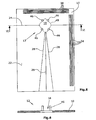
- FIGS. 5 and 6 are identical or similar components or features with the same reference numerals.
- FIGS. 5 and 6 The only difference between the two adjustment systems shown as preferred embodiments in the figures is that in a second embodiment ( FIGS. 5 and 6 ) 16 projections or pins 46 are provided instead of a wall element.
- the pins 46 are arranged along an outer contour line 48, so that a latching element 14 can be arranged in a precise position within the pins 46.
Landscapes
- Health & Medical Sciences (AREA)
- General Health & Medical Sciences (AREA)
- Physical Education & Sports Medicine (AREA)
- Footwear And Its Accessory, Manufacturing Method And Apparatuses (AREA)
Description
- Die Erfindung betrifft ein Rastelement-Justagesystem für Fahrradschuhe.
- Fahrradschuhe, die insbesondere in Verbindung mit Mountainbike-, Rennrad- und Triathlon-Pedalen eingesetzt werden, weisen ein Befestigungssystem zum Befestigen bzw. Einklicken des Schuhs an dem Pedal auf. Ein bekanntes Klick-System, das insbesondere bei Mountainbike-Schuhen verwendet ist, stammt von der Fa. Shimano Inc. und wird und wird unter der Bezeichnung SPD vertrieben.
- Die mit der Sohle des Fahrradschuhs zu verbindenden Rastelemente, die häufig als Cleats bezeichnet werden, müssen möglichst genau justiert werden. Die Befestigung der Rastelemente erfolgt üblicherweise mittels zweier Schrauben. Die Schrauben werden durch in der Schuhsohle vorgesehene Langlöcher gesteckt und greifen in eine auf der Schuhinnenseite vorgesehene Gewindeplatte. Da in der Schuhsohle in Längsrichtung des Schuhs Langlöcher ausgebildet sind, können die Rastelemente in Längsrichtung justiert werden. Das Rastelement selbst weist im Bereich, in dem die Schrauben hindurchgeführt sind und die Schraubenköpfe aufgenommen werden, ebenfalls als Langlöcher ausgebildete Öffnungen auf. Die Ausrichtung dieser Langlöcher ist quer zur Schuh-Längsrichtung. Hiermit kann ein seitliches Verschieben bzw. Ausrichten des Rastelements hinsichtlich des Schuhs erfolgen.
- In der Praxis ist die genaue Justage der Rastelemente an dem Fahrradschuh schwierig und beruht im Wesentlichen auf "Try and Error". Ein Ausmessen oder Bestimmen der exakten Lage ist nicht möglich. Dies führt dazu, dass häufiger ein mehrfaches Nachstellen erforderlich ist, bis eine für den Benutzer angenehme Lage des Rastelements gefunden wurde. Eine falsche Justierung des Rastelements kann hierbei zu Knieproblemen und sogar zu dauerhaften Beschädigungen im Kniegelenk führen.
- Die Lage der Rastelemente an beiden Schuhen sollte möglichst gleich sein. Dies erfolgt heute dadurch, dass der Benutzer die Schuhe von unten betrachtet und die Lage der Rastelemente nach Augenmaß einstellt. Dies führt häufig zu Fehleinstellungen, da die Schuhsohle hinsichtlich des Oberschuhs häufig seitlich versetzt ist. Dies hat zufolge, dass selbst eine exakt gleiche Anordnung der Rastelemente an der Schuhsohle nicht gewährleistet, dass das Rastelement bezogen auf den Fuß des Benutzers in der gleichen Lage angeordnet ist.
- Ferner sollte bei der Anordnung der Cleats berücksichtigt werden, dass der Schuh beim Treten die Tretkurbel nicht berührt. Insbesondere beim Nachjustieren einer Schrägstellung, wenn beispielsweise die Ferse nach innen gedreht wird, kann ein Berühren der Ferse oder des Knöchels an der Tretkurbel auftreten. Dies hat zufolge, dass die seitliche Anordnung des Rastelements verändert werden muss. Dies ist nicht nur aufwändig sondern führt häufig dazu, dass ein ungewolltes Verstellen der Lage, insbesondere auch in Längsrichtung erfolgt.
- Aus
WO 2005/025974 ist ein gattungsgemäβes Rastelement-Justagesystem für Fahrradschuhe bekannt. Dieses weist eine Grundplatte auf, auf der der Fahrradschuh mit Halteelementen fixiert wird, so dass der Fahrradschuh relativ zur Grundplatte weder in Längsrichtung noch quer zur Längsrichtung verschiebbar ist. - Das Rastelement ist in einem schwenkbaren Halter angeordnet. Der Halter ist mit der Grundplatte verschwenkbar verbunden. Durch Verschwenken des Halters kann ein zuvor bekannter Neigungswinkel des Rastelements relativ zur Längsachse des Schuhs eingestellt werden.
- Aufgabe der Erfindung ist es, ein Rastelement-Justagesystem für Fahrradeschuhe sowie ein entsprechendes Verfahren zu schaffen, mit dem auf einfache Art und Weise Rastelemente für Fahrradschuhe justiert werden können,
- Die Lösung der Aufgabe erfolgt erfindungsgemäß durch die Merkmale des Anspruchs 1 bzw. 13.
- Das erfindungsgemäße Rastelement-Justagesystem für Fahrradschuhe weist ein Basiselement sowie ein mit dem Basiselement verbundenes Aufnahmeelement auf. Das Aufnahmeelement dient zur Aufnahme des mit dem Fahrradschuh lagegenau zu verbindenden Rastelements bzw. Cleats. Hierbei ist das Aufnahmeelement derart ausgebildet, dass mit Hilfe des Aufnahmeelements zunächst eine definierte, lagegenaue Aufnahme bzgl. des Basiselements erfolgen kann. Dies kann beispielsweise dadurch erfolgen, dass das Basiselement eine Markierung aufweist, an der das Aufnahmeelement beispielsweise durch Aufkleben mit dem Basiselement verbunden wird. Erfindungsgemäß weist das Basiselement Justageelemente auf. Hierbei kann es sich um Markierungen für den seitlichen Abstand des Rastelements zur Tretkurbel, für die Winkellage der Ferse des Schuhs, für die Ausrichtung des Cleats in Längsrichtung bzw. relativ zur Pedalachse etc. handeln.
- Ferner weisen die Justageelemente erfindungsgemäß mehrere in unterschiedlichem Abstand zum Aufnahmeelement angeordnete Kurbellinien auf, die den Abstand zwischen Aufnahmeelement und Tretkurbel anzeigen.
- Das Aufnahmeelement kann mit dem Basiselement beispielsweise durch Verkleben, durch Fixierelemente oder dergleichen verbunden sein. Insbesondere kann das Basiselement mit dem Aufnahmeelement auch einstückig ausgebildet, beispielsweise aus Kunststoff hergestellt sein.
- Bei einer weiteren Ausführungsform der Erfindung ist das Aufnahmeelement zur Aufnahme des Cleats ein von dem Basiselement unabhängiges Bauteil. Dies hat den Vorteil, dass der Schuh, an den das Cleat montiert werden soll, hinsichtlich des Basiselements bzw. hinsichtlich an dem Basiselement vorgesehener Justagelemente zunächst ausgerichtet werden kann und beispielsweise über Halteelemente in dieser Lage fixiert werden kann. Anschließend kann die exakte Lage des Aufnahmeelements relativ zum Schuh durch Verschieben und/ oder Verdrehen des Aufnahmeelements erfolgen. Hierzu kann das Aufnahmeelement mit einem Halteelement, wie einem Stab, verbunden sein, Das Halteelement ragt vorzugweise seitlich über das Basiselement vor, so dass das Aufnahmeelement durch das Halteelement bewegt werden kann, während das Basiselement beispielsweise mit darauf angeordnetem Schuh von oben betrachtet wird. Das Basiselement kann ein Führungselement aufweisen, in dem das Halteelement beispielsweise gehalten und geführt ist. Das Führungselement dient insbesondere dazu, dass das Halteelement stets an einer Unterseite des Basiselements anliegt, da bei einem ebenen Basiselement lediglich ein Verschieben des Cleats in einer Ebene erforderlich ist. Senkrecht zu dieser Ebene bzw. senkrecht zu der Schuhsole ist ein Verschieben des Cleats nicht erforderlich.
- Mit Hilfe des erfindungsgemäßen Rastelement-Justagesystems kann somit das Rastelement zunächst in definierter Lage zu dem Basiselement gebracht werden. Mit Hilfe der auf dem Basiselement vorgesehenen Justageelemente, bei denen es sich um Markierungen, wie Linien, Winkelangaben und dergleichen handeln kann, ist es sodann möglich, die exakte Lage des Rasteelements relativ zu dem Fahrradschuh einzustellen. Insbesondere ist es möglich, die Lage eines mit dem Fahrradschuh verbundenen Rastelements über die Justageelemente abzulesen. Somit kann die Lage eines Rastelements von einem Schuh auf einen anderen Schuh mit Hilfe des Justagesystems auf einfache Weise übertragen werden. Dies hat den Vorteil, dass die Rastelemente tatsächlich an beiden Schuhen die gleiche Lage aufweisen. Ferner ist es möglich, beispielsweise beim Austausch von Rastelementen die Lage des auszutauschenden Rastelements zunächst zu bestimmen und sodann das neue Rastelement an der exakt gleichen Stelle des Schuhs wieder zu befestigen.
- Um eine möglichst genaue und einfache Anordnung des Rastelements relativ zum Basiselement und damit zu den auf dem Basiselement vorgesehenen Justagelementen bzw. Justagemarkierungen vornehmen zu können, erfolgt vorzugsweise eine formschlüssige Aufnahme des Rastelements durch das Aufnahmeelement. Das Aufnahmeelement weist vorzugsweise Ansätze auf, die beispielsweise eine formschlüssige Aufnahme ermöglichen. Die beispielsweise stiftförmigen Ansätze sind vorzugsweise derart angeordnet, dass die Aufnahme des Rastelements zwischen den Ansätzen erfolgt, wobei vorzugsweise mindestens drei Ansätze vorgesehen sind, an denen das Rastelement anliegt. Vorzugsweise sind die Ansätze daher auf einer Außenkonturlinie des Rastelements angeordnet.
- Besonders bevorzugt ist es, dass die Form bzw. Kontur der Ansätze jeweils einem Teil der Außenkontur des Rastelements zumindest teilweise entspricht. Die einzelnen Ansätze sind somit entsprechend einer Wand ausgebildet, deren Form einem Teil der Außenkonturlinie zumindest teilweise entspricht.
- In einer besonders bevorzugten Ausführungsform ist ein einziger Ansatz bzw. ein Wandelement vorgesehen, dass das Rastelement umgibt. Hierbei entspricht die Form bzw. Kontur des Wandelements zumindest teilweise der Außenkonturlinie des Rastelements.
- Vorzugsweise sind die einzelnen Ansätze oder das Wandelemente derart ausgebildet, dass Rastelemente verschiedener Hersteller lagegenau, insbesondere formschlüssig, durch das Aufnahmeelement aufgenommen und somit exakt hinsichtlich des Basiselements angeordnet sind.
- Vorzugsweise weist das Aufnahmeelement eine Durchgangsöffnung auf, um beispielsweise bei auf der Schuhsohle aufliegendem Rastelement-Justagesystem die Befestigungsschrauben der Rastelemente anziehen zu können. Hierbei ist entweder das gesamte Aufnahmeelement als Durchgangsöffnung ausgebildet oder es ist zumindest eine Durchgangsöffnung vorgesehen, die die Schrauben freigibt.
- Vorzugsweise handelt es sich bei dem Basiselement um eine ebene Platte, die zumindest teilweise transparent ist. Besonders bevorzugt ist es, das Basiselement zusammen mit dem Aufnahmeelement einstückig auszubilden, wobei vorzugsweise Kunststoff verwendet wird. Die Justageelemente umfassen vorzugsweise unmittelbar auf das Basiselement aufgedruckte, eingeprägte etc. Markierungen, bei denen es sich vorzugsweise um Linien handelt. Die Linien können mit Bezeichnungen, die sich beispielsweise auf bestimmte Pedaltypen beziehen, Ziffern oder Buchstaben versehen sein. Insbesondere umfassen die Justageelemente eine Pedallinie, durch die die Pedalachse abgebildet ist. Ferner kann eine Längssymmetrlelinie als ein weiteres Justageelement vorgesehen sein. Die Längssymmetrielinie ist eine Verlängerung der Symmetrielinie des Rastelements. Die Längssymmetrielinie steht vorzugsweise über das Fersenelement des Fahrradschuhs vor, so dass bei Betrachten des auf einem Rastelement-Justagesystem stehenden Fahrradschuhs von oben die Längssymmetrielinie sichtbar ist.
- Neben der Längssymmetrielinie können insbesondere fächerartig weitere Linien angeordnet sein. Sämtliche Linien schneiden sich vorzugsweise mit der Längssymmetrielinie im Mittelpunkt des Rastelements, insbesondere auf dem Schnittpunkt zwischen der Längssymmetrielinie und der Pedallinie. Des Weiteren können die Justageelemente Kurbellinien aufweisen. Hierbei handelt es sich um Linien, die parallel zur Längssymmetrielinie in einem Abstand zum Aufnahmeelement angeordnet sind und den Abstand zwischen Aufnahmeelement und Tretkurbel veranschaulichen. Insbesondere die Kurbellinien können mit der Bezeichnung von Pedaltypen versehen sein, da im Wesentlichen durch den Pedaltyp der Abstand zwischen der RastelementAufnahme des Pedals und der Tretkurbel, und somit zwischen dem Rastelement und der Tretkurbel, definiert ist.
- Ferner können als Justageelemente Übertragungslinien oder Übertragungsmarkierungen auf dem Basiselement vorgesehen sein. Diese dienen zur Übertragung der Lage eines Rastelements auf den jeweils anderen Schuh, oder um beim Austausch von Rastelementen das neue Rastelement in der exakt gleichen Lage wie das alte Rastelement an dem Schuh anzubringen. Das Aufnahmeelement zur Aufnahme des Rastelements weist insbesondere die Außenkontur eines Rastelements handelsüblicher Rastelemente bzw. Cleats auf. Hierbei handelt es sich insbesondere um Cleats der Fa. Shimano mit der Bezeichnung "SPD" sowie um Cleats der Fa. Look.
- Das Basiselement ist insbesondere flächig ausgebildet und weist eine Größe auf, so dass der gesamte Schuh auf dem Basiselement aufsteht. Bevorzugt ist es hierbei, dass das Basiselement im Querschnitt im Bereich der Ferse eine Erhöhung aufweist, so dass der vordere Teil des Fahrradschuhs, an dem das Cleat befestigt ist, im Wesentlichen parallel zum Basiselement verläuft. Hierdurch ist sichergestellt, dass das Rastelement bzw. Cleat sicher in einem Ansatz bzw. Rahmenelement des Aufnahmeelements gehalten ist. Das vorzugsweise aus Kunststoff hergestellte Basiselement ist in besonders bevorzugter Ausführungsform zumindest im Bereich der Fersenerhöhung hohl ausgebildet. Hierdurch kann ein Fach ausgebildet werden, in dem eine Handhabungsanleitung oder dgl. untergebracht werden kann.
- Vorzugsweise ist für den linken und den rechten Schuh jeweils ein gesondertes Basiselement vorgesehen. Diese können miteinander verbunden oder einstückig ausgebildet sein. Bevorzugt ist es hierbei, dass die beiden Basiselemente klappbar miteinander verbunden sind, so dass der Stauraum gering ist. Die Verbindung kann hierbei über ein Filmgelenk oder dgl. erfolgen.
- Nachfolgend wird die Erfindung anhand einer bevorzugten Ausführungsform unter Bezugnahme auf die anliegenden Zeichnungen näher erläutert.
- Es zeigen:
- Fig. 1
- eine schematische Draufsicht einer bevorzugten Ausführungsform des erfindungsgemäßen Rastelement-Justagesystems,
- Fig. 2
- eine schematische Schnittansicht entlang der Linie II-II,
- Fig. 3
- eine schematische Unteransicht eines Fahrradschuhs mit auf die Sohle des Fahrradschuhs aufgelegtem Rastelement-Justagesystem,
- Fig. 4
- eine schematische Draufsicht eines Rastelement-Justagesystems für beide Schuhe mit einem einzelnen schematisch dargestellten Schuh,
- Fig. 5
- eine schematische Draufsicht einer weiteren Ausführungsform des Rastelement-Justagesystems, und
- Fig. 6
- eine schematische Schnittansicht entlang der Linie VI-VI in
Fig. 5 . - Ein insbesondere aus transparentem Kunststoff hergestelltes Basiselement 10 ist in bevorzugter Ausführungsform einstückig mit einem Aufnahmeelement 12 verbunden. In der ersten bevorzugten Ausführungsform (
Fig. 1 bis 4 ) weist das Aufnahmeelement zur lagegenauen Anordnung eines Rastelements 14 (Fig. 3 ) ein Wandelement 16 auf, das das Rastelement 14 vollständig umgibt. Das Wandelement 16 weist eine Kontur auf, die der Außenkontur des Rastelements 14 entspricht, so dass das Rastelement 14 in einer Öffnung 18 (Fig. 1 ) des Aufnahmeelements 12 formschlüssig aufgenommen ist. Die Öffnung 18 ist als Durchgangsöffnung ausgebildet, wobei die Größe der Öffnung der Grundfläche des Rastelements entspricht, so dass das Rastelement durch die Öffnung 18 hindurchgesteckt werden könnte. Ggf. sind Teile der Öffnung 18, insbesondere in Bereichen, in denen keine Befestigungsschrauben 20 (Fig. 3 ) vorgesehen sind, verschlossen, um das Rastelement in das Basiselement 10 einlegen zu können und ein Herausfallen oder Hindurchrutschen des Rastelements 14 zu vermeiden. - Im dargestellten Ausführungsbeispiel sind Justageelemente auf einer Oberseite 22 des Basiselements 1 angeordnet. Hierbei handelt es sich um Markierungen, die beispielsweise aufgedruckt sind.
- Ein Justageelement besteht aus einer Pedallinie 24. Die Pedallinie markiert die Pedalachse. Es handelt sich somit um die Mittelachse des Pedals, um das das Pedal gedreht wird. Über diese Achse wird die Kraft beim Treten auf die Tretkurbel übertragen.
- Ein weiteres Justageelement besteht in der Längssymmetrieachse 26. Es handelt sich hierbei um die Längssymmetrieachse des Rastelements bzw. deren auf der Oberseite 22 des Basiselements 10 dargestellten Verlängerung. In einem jeweils gleichen Winkel zu der Längssymmetrielinie sind fächerförmig im dargestellten Ausführungsbeispiel zwei Fersenlinien 28 vorgesehen, die zur Justage des Verschwenkens des Fersenelements 30 (
Fig. 4 ) des Fahrradschuhs 32 dient. - Weitere Justageelemente bestehen in parallel zur Längssymmetrielinie 26 verlaufenden Kurbellinien 34. Mit Hilfe der Kurbellinien kann ein Abstand des Rastelements bzw. der Mitte des Rastelements zu der Tretkurbel definiert werden. Ggf. sind die einzelnen Kurbellinien 34 mit Ziffern oder Buchstaben versehen. Die Ziffern oder Buchstaben können ggf. Pedaltypen zugeordnet werden, da im Wesentlichen durch den Pedaltyp der Abstand zwischen Rastelement und Tretkurbelarm definiert ist. Auch können die einzelnen interessierenden Pedaltypen unmittelbar auf der Oberfläche 22 des Basiselements 10 aufgedruckt sein.
- Zusätzlich können im Bereich einer Schuhspitze 36 (
Fig. 4 ) parallel zur Pedallinie 24 verlaufende Übertragungslinien 38 (Fig. 1 ) vorgesehen sein. Die Übertragungslinien 38 sind vorzugsweise mit Ziffern versehen (Fig. 4 ). - Zur lagegenauen Montage des Rastelements 14 an einer Schuhsohle 40 eines Fahrradschuhs 32 können die folgenden Schritte durchgeführt werden:
- In einem ersten Schritt wird einer der beiden Schuhe vom Benutzer angezogen und das Großzehengrundgelenk an der Innenseite des Schuhs ertastet. Die Lage des Großzehengrundgelenks wird sodann am Schuh, beispielsweise mit Kreide, einem Aufkleber oder dgl. markiert. Anschließend wird das Rastelement lose mit der Sohle 40 des Schuhs 32 verbunden, indem üblicherweise auf der Innenseite des Schuhs eine Platte mit Gewinden angeordnet wird, in die zur Fixierung des Rastelements Schrauben 20 geschraubt werden. Die Schrauben 20 werden zunächst noch nicht angezogen.
- Nunmehr wird das Rastelement in die Öffnung 18 eingesteckt, wie insbesondere aus der Unteransicht von
Fig. 3 ersichtlich. Der Schuh 32 wird nunmehr in Richtung eines Pfeils 42 (Fig. 4 ) verschoben, bis die Markierung des Großzehengrundgelenks mit der Pedallinie 24 fluchtet. Hierdurch ist gewährleistet, dass eine gute Kraftübertragung auf das Pedal und über die Pedalachse auf die Tretkurbel erfolgt. - Die Justage des Rastelements in Längsrichtung relativ zum Schuh 32 ist somit bereits abgeschlossen. Die Lage kann den Übertragungslinien abgelesen werden.
- Anschließend erfolgt die seitliche Ausrichtung des Schuhs, um ein Berühren der Tretkurbel zu vermeiden. Wünschenswert ist hierbei zur möglichst optimalen Kraftübertragung, dass der Schuh möglichst nah an der Tretkurbel angeordnet ist. Hierzu dienen die Kurbellinien 34. Entweder sind die Kurbellinien pedalspezifisch markiert, so dass eine Ausrichtung des Schuhs in Richtung eines Pfeils 44 (
Fig. 4 ) auf einfache Weise erfolgen kann. Ebenso kann zuvor durch Auflegen des Basiselements 10 auf das Pedal derart, dass die Rastelementaufnahme des Pedals innerhalb der Öffnung 18 angeordnet ist, und durch Peilen entlang der Tretkurbel die entsprechende Kurbellinie 34 festgestellt werden. Es erfolgt nunmehr ein Verschieben des Schuhs in Richtung des Pfeils 44 (Fig. 4 ). - Der Fersenwinkel, d.h. das Verdrehen des Fersenelements 30 des Schuhs 32 ist im Wesentlichen von den anatomischen Gegebenheiten des Benutzers abhängig und muss empirisch ermittelt werden. Zunächst kann von einer Mittelstellung ausgegangen werden, so dass die Mitte des Fersenelements 30 über der Längssymmetrielinie 26 angeordnet ist.
- Die Lage des Rastelements ist nunmehr definiert, so dass die Schrauben 20 angezogen werden können.
- Die lagegenaue Fixierung des Rastelements des zweiten Schuhs ist erheblich einfacher. Hierzu ist es lediglich erforderlich, auf das in
Fig. 4 linke Rastelement-Justagesystem den linken Schuh zu stellen, wobei das noch nicht festgezogene Rastelement wiederum in der Öffnung 18 angeordnet ist. Der linke Schuh wird somit entsprechend dem rechten Schuh ausgerichtet. Hierbei kann die Längsausrichtung in Richtung des Pfeils 42 auf einfache Weise dadurch erfolgen, dass an den Übertragungslinien 38 die entsprechende Lage abgelesen wird und der linke Schuh entsprechend in Richtung des Pfeils 42 verschoben wird. Dies ist auch hinsichtlich der Querverschiebung in Richtung des Pfeils 44 möglich, da die Kurbellinien 34 hierbei ebenfalls als Übertragungslinien genutzt werden können. Die Lage der Ferse ergibt sich hierbei automatisch. - Sofern abgenutzte Rastelemente an einem Schuh 32 ausgetauscht werden sollen, ist es am einfachsten, vor der Demontage der Rastelemente den Schuh mit den alten Rastelementen auf das Rastelement-Justagesystem aufzustellen, wobei das alte Rastelement innerhalb der Durchgangsöffnung 18 angeordnet ist. Die Lage der Schuhspitze 36 sowie einer Schuhinnenseite 45 kann somit an den Übertragungslinien 38, 34 abgelesen werden. Anschließend wird das neue Rastelement lose montiert, der Schuh wiederum auf das Basiselement 10 gestellt und entsprechend der notierten Übertragungslinien 34, 38 ausgerichtet. Sodann können die Schrauben 20 des neuen Rastelements angezogen werden.
- Bei einer weiteren Ausführungsform (
Fig. 5 und 6 ) des Rastelement-Justagesystems sind identische oder ähnliche Bauteile bzw. Merkmale mit denselben Bezugszeichen gekennzeichnet. - Der einzige Unterschied der beiden als bevorzugte Ausführungsformen in den Fig. dargestellten Justagesystemen besteht darin, dass bei einer zweiten Ausführungsform (
Fig. 5 und 6 ) anstelle eines Wandelements 16 Ansätze bzw. Pins 46 vorgesehen sind. Die Pins 46 sind entlang einer Außenkonturlinie 48 angeordnet, so dass ein Rastelement 14 innerhalb der Pins 46 lagegenau angeordnet werden kann. - Die Justage der Rastelemente an einem Fahrradschuh erfolgt auch mit dem in den
Fig. 5 und 6 dargestellten Rastelement-Justagesystem, wie vorstehend anhand der ersten bevorzugten Ausführungsform beschieben.
Claims (15)
- Rastelement-Justagesystem für Fahrradschuhe, mit einem Basiselement (10),
einem mit dem Basiselement (10) verbundenen Aufnahmeelement (12) zur Aufnahme des Rastelements, und
auf dem Basiselement (10) vorgesehenen Justageelementen (24, 26, 28, 34, 38),
wobei das Aufnahmeelement (12) mit dem Basiselement (10) fest verbunden ist, so dass das Rastelement (14) relativ zum Basiselement (10) lagegenau angeordnet ist
dadurch gekennzeichnet, dass
die Justageelemente mehrere in unterschiedlichem Abstand zum Aufnahmeelement (12) angeordnete Kurbellinien (34) aufweisen, die den Abstand zwischen Aufnahmeelement (12) und Tretkurbel anzeigen. - Rastelement-Justagesystem nach Anspruch 1, dadurch gekennzeichnet, dass das Aufnahmeelement (12) das Rastelement (14) formschlüssig aufnimmt.
- Rastelement-Justagesystem nach Anspruch 1 oder 2, dadurch gekennzeichnet, dass das Aufnahmeelement (12) Ansätze (46, 16) aufweist, durch die, Insbesondere zwischen denen, das Rastelement (14) lagegenau angeordnet ist.
- Rastelement-Justagesystem nach Anspruch 3, dadurch gekennzeichnet, dass die Ansätze (46, 16) auf einer Außenkonturlinie (48) des Rastelements (14) angeordnet sind.
- Rastelement-Justagesystem nach Anspruch 3 oder 4, dadurch gekennzeichnet, dass die Form der Ansätze (16) jeweils einem Teil der Außenkontur des Rastelements (14) zumindest teilweise entspricht.
- Rastelement-Justagesystem nach einem der Ansprüche 1 bis 5, dadurch gekennzeichnet, dass das Aufnahmeelement (12) ein das Rastelement (14) zumindest teilweise umgebendes Wandelement (16) aufweist, dessen Form zumindest teilweise der Außenkontur des Rastelements (14) entspricht.
- Rastelement-Justagesystem nach einem der Ansprüche 1 bis 6, dadurch gekennzeichnet, dass das Aufnahmeelement (12) eine Durchgangsöffnung (18) aufweist, die sich zumindest über einen Teil der Grundfläche des Rastelements (14) erstreckt.
- Rastelement-Justagesystem nach einem der Ansprüche 1 bis 7, dadurch gekennzeichnet, dass das Basiselement (10) eine ebene Platte aufweist, die insbesondere zumindest teilweise transparent ist.
- Rastelement-Justagesystem nach einem der Ansprüche 1 bis 8, dadurch gekennzeichnet, dass das Basiselement (10) und das Aufnahmeelement (12) einstückig, insbesondere aus Kunststoff, hergestellt sind.
- Rastelement-Justagesystem nach einem der Ansprüche 1 bis 9, dadurch gekennzeichnet, dass die Justageelemente eine durch das Rastelement (14) verlaufende Pedallinie (24) aufweisen, die die Pedalachse abbildet und/oder die Justageelemente eine Längssymmetrielinie (26) aufweisen, die eine Verlängerung der Längssymmetrielinie des Rastelements (14) ist.
- Rastelement-Justagesystem nach Anspruch 10, dadurch gekennzeichnet, dass die Längssymmetrielinie (26) bei auf das Basiselement (10) zur Montage des Rastelements (14) aufgestelltem Fahrradschuh (32) über das Fersenelement (30) des Fahrradschuhs (32) vorsteht.
- Rastelement-Justagesystem nach einem der Ansprüche 1 bis 11, dadurch gekennzeichnet, dass die Justageelemente mehrere Übertragungslinien (38, 34) zur Übertragung von Justageeinstellungen von einem Fahrradschuh (32) auf einen anderen Fahrradschuh (32) aufweisen.
- Verfahren zur Justage eines Rastelements an einem Fahrradschuh mit Hilfe eines Rastelement-Justagesystems nach einem der Ansprüchen 1 bis 12, bei welchem
die Lage des Großzehengelenks an dem Schuh markiert wird,
das Rastelement lose mit der Sohle des Schuhs verbunden wird,
das Rastelement in die Öffnung (18) des Aufnahmeelements (12) eingesteckt wird,
der Schuh verschoben wird, bis die Markierung des Großzehengelenks mit der Pedallinie (24) fluchtet und
der Schuh seitlich anhand der Kurbellinien (34) ausgerichtet wird. - Verfahren nach Anspruch 13, dadurch gekennzeichnet, dass ein Fersenwinkel eingestellt wird.
- Verfahren nach Anspruch 13 oder 14, bei welchem die Lage des Rastelements mit Hilfe der Justageelemente (24, 26, 28, 34, 38) auf einen zweiten Schuh übertragen wird.
Applications Claiming Priority (2)
| Application Number | Priority Date | Filing Date | Title |
|---|---|---|---|
| DE202007012024U DE202007012024U1 (de) | 2007-08-28 | 2007-08-28 | Rastelement-Justagesystem für Fahrradschuhe |
| PCT/EP2008/061021 WO2009027338A1 (de) | 2007-08-28 | 2008-08-22 | Rastelement-justagesystem für fahrradschuhe |
Publications (2)
| Publication Number | Publication Date |
|---|---|
| EP2182823A1 EP2182823A1 (de) | 2010-05-12 |
| EP2182823B1 true EP2182823B1 (de) | 2012-03-14 |
Family
ID=40090071
Family Applications (1)
| Application Number | Title | Priority Date | Filing Date |
|---|---|---|---|
| EP08787422A Active EP2182823B1 (de) | 2007-08-28 | 2008-08-22 | Rastelement-justagesystem für fahrradschuhe |
Country Status (6)
| Country | Link |
|---|---|
| US (1) | US8474145B2 (de) |
| EP (1) | EP2182823B1 (de) |
| AT (1) | ATE548930T1 (de) |
| DE (1) | DE202007012024U1 (de) |
| TW (1) | TWI373312B (de) |
| WO (1) | WO2009027338A1 (de) |
Families Citing this family (10)
| Publication number | Priority date | Publication date | Assignee | Title |
|---|---|---|---|---|
| US8196243B2 (en) | 2009-07-29 | 2012-06-12 | Pedal Pushers Cycles Pty Ltd | Functional fitting of cyclists in clipless pedal systems |
| US20120017471A1 (en) * | 2010-01-26 | 2012-01-26 | Erik Henry Tews | Shoe accessory for cycling |
| US9254016B2 (en) | 2011-01-20 | 2016-02-09 | Erik Henry Tews | Device for adapting a shoe to attach a cycling cleat |
| US9089183B2 (en) * | 2012-05-30 | 2015-07-28 | Shimano Inc. | Bicycle cleat positioning kit |
| DE102013101076B4 (de) | 2012-05-30 | 2019-10-24 | Shimano Inc. | Positioniervorrichtung für eine fahrrad-schuhplatte |
| US9848669B2 (en) | 2012-06-19 | 2017-12-26 | Shimano Inc. | Bicycle cleat positioining device |
| US8984759B2 (en) * | 2012-05-30 | 2015-03-24 | Shimano Inc. | Bicycle cleat positioning kit and bicycle cleat positioning method |
| US9307805B2 (en) | 2013-04-25 | 2016-04-12 | Shimano Inc. | Bicycle cleat positioning kit |
| FR3043052B1 (fr) * | 2015-10-29 | 2018-11-30 | Specialiste Velos | Procede de reglage de la position d'un cycliste sur un velo de route, notamment des membres inferieurs, dispositifs de compensation |
| US11503882B1 (en) | 2021-10-04 | 2022-11-22 | Bike Energy Lab Ltd. | Bike cleat fitting tool system and methods of use |
Family Cites Families (11)
| Publication number | Priority date | Publication date | Assignee | Title |
|---|---|---|---|---|
| US1436111A (en) * | 1921-04-07 | 1922-11-21 | Reich Julius | Surface-test indicator |
| FR2608025B1 (fr) | 1986-12-16 | 1989-03-10 | Beyl Jean Joseph Alfred | Gabarit pour faciliter le reglage d'une cale sous la semelle d'une chaussure cycliste, semelle et chaussure cycliste adaptees a un tel gabarit |
| US4771548A (en) * | 1987-06-29 | 1988-09-20 | Donnery Joseph P | Biplane goniometer |
| IT1293473B1 (it) * | 1997-05-06 | 1999-03-01 | Calzaturificio Piva Srl | Attrezzatura per il posizionamento delle placchette di ancoraggio al pedale su una suola di calzatura per ciclismo |
| ITBO20030534A1 (it) * | 2003-09-15 | 2005-03-16 | Diamant S R L | Dispositivo di regolazione per attacchi ad aggancio rapido per pedali |
| CA2485324A1 (fr) * | 2004-11-16 | 2006-05-16 | Yvan Champoux | Methode et appareil pour la mesure in situ du mouvement angulaire des pedales automatiques commerciales |
| FR2879412B1 (fr) * | 2004-12-21 | 2007-06-08 | Promiles Sa | Pedimetre |
| US20060248965A1 (en) * | 2005-05-06 | 2006-11-09 | Wyatt Roland J | Systems and methods of power output measurement |
| US7536794B2 (en) * | 2005-05-20 | 2009-05-26 | Bivab, Llc | Foot measurement, alignment and evaluation device |
| US7599806B2 (en) * | 2006-03-17 | 2009-10-06 | Gunter Hauschildt | Portable power meter for calculating power applied to a pedal and crank arm based drive mechanism and a method of calculating the power |
| IL188645A (en) * | 2008-01-07 | 2011-12-29 | Eliaho Gerby | Foot measuring device |
-
2007
- 2007-08-28 DE DE202007012024U patent/DE202007012024U1/de not_active Expired - Lifetime
-
2008
- 2008-08-22 WO PCT/EP2008/061021 patent/WO2009027338A1/de not_active Ceased
- 2008-08-22 EP EP08787422A patent/EP2182823B1/de active Active
- 2008-08-22 US US12/675,574 patent/US8474145B2/en active Active
- 2008-08-22 AT AT08787422T patent/ATE548930T1/de active
- 2008-08-27 TW TW097132787A patent/TWI373312B/zh not_active IP Right Cessation
Also Published As
| Publication number | Publication date |
|---|---|
| DE202007012024U1 (de) | 2009-01-08 |
| TWI373312B (en) | 2012-10-01 |
| EP2182823A1 (de) | 2010-05-12 |
| TW200944147A (en) | 2009-11-01 |
| ATE548930T1 (de) | 2012-03-15 |
| US8474145B2 (en) | 2013-07-02 |
| US20100307030A1 (en) | 2010-12-09 |
| WO2009027338A1 (de) | 2009-03-05 |
Similar Documents
| Publication | Publication Date | Title |
|---|---|---|
| WO2009027338A1 (de) | Rastelement-justagesystem für fahrradschuhe | |
| DE69216472T2 (de) | Vorrichtung für Fahrradpedale mit variabler Tretfläche | |
| DE69533009T2 (de) | Gerät zur Knochengrößenbestimmung | |
| DE602004004448T2 (de) | Fahrradschuh mit Schuhhalter eines Pedals mit automatischer Befestigung | |
| DE69202038T2 (de) | Kupplungsanordnung zwischen Fahrradpedal und Stossplatte. | |
| DE4323575C2 (de) | Sicherheitspedal für ein Fahrrad oder dergleichen | |
| DE102013203112B4 (de) | Positionierkit für eine Fahrrad-Schuhplatte | |
| DE69804912T2 (de) | Fahrradschuh | |
| DE4040727A1 (de) | Fahrradschuh | |
| DE102013203202B4 (de) | Positionierkit für eine Fahrrad-Schuhplatte und Positionierverfahren für eine Fahrrad-Schuhplatte | |
| DE102014105691B4 (de) | Fahrradpedal | |
| DE60103212T2 (de) | Fahrradpedal mit justierbarer Position | |
| DE102014206107B4 (de) | Positionierkit für eine fahrrad-schuhplatte | |
| EP0873816B1 (de) | Positionier-Schnellspannzylinder | |
| DE202008004593U1 (de) | Markierungsinstrument | |
| DE102012217692B4 (de) | Fahrradschalteinrichtung aufweisend eine Anzeigeeinheit | |
| DE3822663A1 (de) | Pedal-bindung | |
| DE102013101076B4 (de) | Positioniervorrichtung für eine fahrrad-schuhplatte | |
| EP0756919A1 (de) | Vorrichtung zum Stanzen von bandförmigen und bogenförmigen Material | |
| DE1942885B1 (de) | Beschlag zur Befestigung an der Sohle von Radrennschuhen | |
| DE60002653T2 (de) | Vorrichtung zur verstellung einer platte auf einem zylinder mit magnetischen befestigungselementen | |
| DE4040728C2 (de) | Fahrradschuh | |
| AT397918B (de) | Ski-skibindungskombination | |
| DE69612818T2 (de) | Verbindungsvorrichtung auf einem Radfahrerschuh | |
| DE19845467A1 (de) | Vorrichtung zum Halten eines Schuhes auf einem Gleitbrett |
Legal Events
| Date | Code | Title | Description |
|---|---|---|---|
| PUAI | Public reference made under article 153(3) epc to a published international application that has entered the european phase |
Free format text: ORIGINAL CODE: 0009012 |
|
| 17P | Request for examination filed |
Effective date: 20091118 |
|
| AK | Designated contracting states |
Kind code of ref document: A1 Designated state(s): AT BE BG CH CY CZ DE DK EE ES FI FR GB GR HR HU IE IS IT LI LT LU LV MC MT NL NO PL PT RO SE SI SK TR |
|
| AX | Request for extension of the european patent |
Extension state: AL BA MK RS |
|
| DAX | Request for extension of the european patent (deleted) | ||
| GRAP | Despatch of communication of intention to grant a patent |
Free format text: ORIGINAL CODE: EPIDOSNIGR1 |
|
| GRAS | Grant fee paid |
Free format text: ORIGINAL CODE: EPIDOSNIGR3 |
|
| RAP1 | Party data changed (applicant data changed or rights of an application transferred) |
Owner name: RTI SPORTS VERTRIEB VON SPORTARTIKELN GMBH |
|
| GRAA | (expected) grant |
Free format text: ORIGINAL CODE: 0009210 |
|
| AK | Designated contracting states |
Kind code of ref document: B1 Designated state(s): AT BE BG CH CY CZ DE DK EE ES FI FR GB GR HR HU IE IS IT LI LT LU LV MC MT NL NO PL PT RO SE SI SK TR |
|
| REG | Reference to a national code |
Ref country code: GB Ref legal event code: FG4D Free format text: NOT ENGLISH |
|
| REG | Reference to a national code |
Ref country code: AT Ref legal event code: REF Ref document number: 548930 Country of ref document: AT Kind code of ref document: T Effective date: 20120315 Ref country code: CH Ref legal event code: EP |
|
| REG | Reference to a national code |
Ref country code: IE Ref legal event code: FG4D Free format text: LANGUAGE OF EP DOCUMENT: GERMAN |
|
| REG | Reference to a national code |
Ref country code: DE Ref legal event code: R096 Ref document number: 502008006699 Country of ref document: DE Effective date: 20120510 |
|
| REG | Reference to a national code |
Ref country code: NL Ref legal event code: T3 |
|
| PG25 | Lapsed in a contracting state [announced via postgrant information from national office to epo] |
Ref country code: LT Free format text: LAPSE BECAUSE OF FAILURE TO SUBMIT A TRANSLATION OF THE DESCRIPTION OR TO PAY THE FEE WITHIN THE PRESCRIBED TIME-LIMIT Effective date: 20120314 Ref country code: HR Free format text: LAPSE BECAUSE OF FAILURE TO SUBMIT A TRANSLATION OF THE DESCRIPTION OR TO PAY THE FEE WITHIN THE PRESCRIBED TIME-LIMIT Effective date: 20120314 Ref country code: NO Free format text: LAPSE BECAUSE OF FAILURE TO SUBMIT A TRANSLATION OF THE DESCRIPTION OR TO PAY THE FEE WITHIN THE PRESCRIBED TIME-LIMIT Effective date: 20120614 |
|
| LTIE | Lt: invalidation of european patent or patent extension |
Effective date: 20120314 |
|
| PG25 | Lapsed in a contracting state [announced via postgrant information from national office to epo] |
Ref country code: LV Free format text: LAPSE BECAUSE OF FAILURE TO SUBMIT A TRANSLATION OF THE DESCRIPTION OR TO PAY THE FEE WITHIN THE PRESCRIBED TIME-LIMIT Effective date: 20120314 Ref country code: GR Free format text: LAPSE BECAUSE OF FAILURE TO SUBMIT A TRANSLATION OF THE DESCRIPTION OR TO PAY THE FEE WITHIN THE PRESCRIBED TIME-LIMIT Effective date: 20120615 Ref country code: FI Free format text: LAPSE BECAUSE OF FAILURE TO SUBMIT A TRANSLATION OF THE DESCRIPTION OR TO PAY THE FEE WITHIN THE PRESCRIBED TIME-LIMIT Effective date: 20120314 |
|
| PG25 | Lapsed in a contracting state [announced via postgrant information from national office to epo] |
Ref country code: CY Free format text: LAPSE BECAUSE OF FAILURE TO SUBMIT A TRANSLATION OF THE DESCRIPTION OR TO PAY THE FEE WITHIN THE PRESCRIBED TIME-LIMIT Effective date: 20120314 |
|
| PG25 | Lapsed in a contracting state [announced via postgrant information from national office to epo] |
Ref country code: IS Free format text: LAPSE BECAUSE OF FAILURE TO SUBMIT A TRANSLATION OF THE DESCRIPTION OR TO PAY THE FEE WITHIN THE PRESCRIBED TIME-LIMIT Effective date: 20120714 Ref country code: EE Free format text: LAPSE BECAUSE OF FAILURE TO SUBMIT A TRANSLATION OF THE DESCRIPTION OR TO PAY THE FEE WITHIN THE PRESCRIBED TIME-LIMIT Effective date: 20120314 Ref country code: SI Free format text: LAPSE BECAUSE OF FAILURE TO SUBMIT A TRANSLATION OF THE DESCRIPTION OR TO PAY THE FEE WITHIN THE PRESCRIBED TIME-LIMIT Effective date: 20120314 Ref country code: PL Free format text: LAPSE BECAUSE OF FAILURE TO SUBMIT A TRANSLATION OF THE DESCRIPTION OR TO PAY THE FEE WITHIN THE PRESCRIBED TIME-LIMIT Effective date: 20120314 Ref country code: CZ Free format text: LAPSE BECAUSE OF FAILURE TO SUBMIT A TRANSLATION OF THE DESCRIPTION OR TO PAY THE FEE WITHIN THE PRESCRIBED TIME-LIMIT Effective date: 20120314 Ref country code: SE Free format text: LAPSE BECAUSE OF FAILURE TO SUBMIT A TRANSLATION OF THE DESCRIPTION OR TO PAY THE FEE WITHIN THE PRESCRIBED TIME-LIMIT Effective date: 20120314 Ref country code: RO Free format text: LAPSE BECAUSE OF FAILURE TO SUBMIT A TRANSLATION OF THE DESCRIPTION OR TO PAY THE FEE WITHIN THE PRESCRIBED TIME-LIMIT Effective date: 20120314 |
|
| PG25 | Lapsed in a contracting state [announced via postgrant information from national office to epo] |
Ref country code: SK Free format text: LAPSE BECAUSE OF FAILURE TO SUBMIT A TRANSLATION OF THE DESCRIPTION OR TO PAY THE FEE WITHIN THE PRESCRIBED TIME-LIMIT Effective date: 20120314 Ref country code: PT Free format text: LAPSE BECAUSE OF FAILURE TO SUBMIT A TRANSLATION OF THE DESCRIPTION OR TO PAY THE FEE WITHIN THE PRESCRIBED TIME-LIMIT Effective date: 20120716 |
|
| REG | Reference to a national code |
Ref country code: CH Ref legal event code: NV Representative=s name: ISLER AND PEDRAZZINI AG, CH |
|
| PLBE | No opposition filed within time limit |
Free format text: ORIGINAL CODE: 0009261 |
|
| STAA | Information on the status of an ep patent application or granted ep patent |
Free format text: STATUS: NO OPPOSITION FILED WITHIN TIME LIMIT |
|
| PG25 | Lapsed in a contracting state [announced via postgrant information from national office to epo] |
Ref country code: DK Free format text: LAPSE BECAUSE OF FAILURE TO SUBMIT A TRANSLATION OF THE DESCRIPTION OR TO PAY THE FEE WITHIN THE PRESCRIBED TIME-LIMIT Effective date: 20120314 |
|
| 26N | No opposition filed |
Effective date: 20121217 |
|
| BERE | Be: lapsed |
Owner name: RTI SPORTS VERTRIEB VON SPORTARTIKELN G.M.B.H. Effective date: 20120831 |
|
| PG25 | Lapsed in a contracting state [announced via postgrant information from national office to epo] |
Ref country code: IT Free format text: LAPSE BECAUSE OF FAILURE TO SUBMIT A TRANSLATION OF THE DESCRIPTION OR TO PAY THE FEE WITHIN THE PRESCRIBED TIME-LIMIT Effective date: 20120314 |
|
| REG | Reference to a national code |
Ref country code: CH Ref legal event code: PL |
|
| PG25 | Lapsed in a contracting state [announced via postgrant information from national office to epo] |
Ref country code: MC Free format text: LAPSE BECAUSE OF NON-PAYMENT OF DUE FEES Effective date: 20120831 |
|
| REG | Reference to a national code |
Ref country code: DE Ref legal event code: R097 Ref document number: 502008006699 Country of ref document: DE Effective date: 20121217 |
|
| PG25 | Lapsed in a contracting state [announced via postgrant information from national office to epo] |
Ref country code: CH Free format text: LAPSE BECAUSE OF NON-PAYMENT OF DUE FEES Effective date: 20120831 Ref country code: ES Free format text: LAPSE BECAUSE OF FAILURE TO SUBMIT A TRANSLATION OF THE DESCRIPTION OR TO PAY THE FEE WITHIN THE PRESCRIBED TIME-LIMIT Effective date: 20120625 Ref country code: LI Free format text: LAPSE BECAUSE OF NON-PAYMENT OF DUE FEES Effective date: 20120831 |
|
| REG | Reference to a national code |
Ref country code: IE Ref legal event code: MM4A |
|
| PG25 | Lapsed in a contracting state [announced via postgrant information from national office to epo] |
Ref country code: BE Free format text: LAPSE BECAUSE OF NON-PAYMENT OF DUE FEES Effective date: 20120831 |
|
| PG25 | Lapsed in a contracting state [announced via postgrant information from national office to epo] |
Ref country code: BG Free format text: LAPSE BECAUSE OF FAILURE TO SUBMIT A TRANSLATION OF THE DESCRIPTION OR TO PAY THE FEE WITHIN THE PRESCRIBED TIME-LIMIT Effective date: 20120614 Ref country code: IE Free format text: LAPSE BECAUSE OF NON-PAYMENT OF DUE FEES Effective date: 20120822 |
|
| PG25 | Lapsed in a contracting state [announced via postgrant information from national office to epo] |
Ref country code: MT Free format text: LAPSE BECAUSE OF FAILURE TO SUBMIT A TRANSLATION OF THE DESCRIPTION OR TO PAY THE FEE WITHIN THE PRESCRIBED TIME-LIMIT Effective date: 20120314 |
|
| PG25 | Lapsed in a contracting state [announced via postgrant information from national office to epo] |
Ref country code: TR Free format text: LAPSE BECAUSE OF FAILURE TO SUBMIT A TRANSLATION OF THE DESCRIPTION OR TO PAY THE FEE WITHIN THE PRESCRIBED TIME-LIMIT Effective date: 20120314 |
|
| PG25 | Lapsed in a contracting state [announced via postgrant information from national office to epo] |
Ref country code: LU Free format text: LAPSE BECAUSE OF NON-PAYMENT OF DUE FEES Effective date: 20120822 |
|
| PG25 | Lapsed in a contracting state [announced via postgrant information from national office to epo] |
Ref country code: HU Free format text: LAPSE BECAUSE OF FAILURE TO SUBMIT A TRANSLATION OF THE DESCRIPTION OR TO PAY THE FEE WITHIN THE PRESCRIBED TIME-LIMIT Effective date: 20080822 |
|
| REG | Reference to a national code |
Ref country code: AT Ref legal event code: MM01 Ref document number: 548930 Country of ref document: AT Kind code of ref document: T Effective date: 20130822 |
|
| PGFP | Annual fee paid to national office [announced via postgrant information from national office to epo] |
Ref country code: NL Payment date: 20140821 Year of fee payment: 7 |
|
| PG25 | Lapsed in a contracting state [announced via postgrant information from national office to epo] |
Ref country code: AT Free format text: LAPSE BECAUSE OF NON-PAYMENT OF DUE FEES Effective date: 20130822 |
|
| REG | Reference to a national code |
Ref country code: NL Ref legal event code: MM Effective date: 20150901 |
|
| PG25 | Lapsed in a contracting state [announced via postgrant information from national office to epo] |
Ref country code: NL Free format text: LAPSE BECAUSE OF NON-PAYMENT OF DUE FEES Effective date: 20150901 |
|
| REG | Reference to a national code |
Ref country code: DE Ref legal event code: R082 Ref document number: 502008006699 Country of ref document: DE Representative=s name: DOMPATENT VON KREISLER SELTING WERNER - PARTNE, DE Ref country code: DE Ref legal event code: R081 Ref document number: 502008006699 Country of ref document: DE Owner name: RTI SPORTS GMBH, DE Free format text: FORMER OWNER: RTI SPORTS, VERTRIEB VON SPORTARTIKELN GMBH, 56070 KOBLENZ, DE Ref country code: DE Ref legal event code: R081 Ref document number: 502008006699 Country of ref document: DE Owner name: ERGON INTERNATIONAL GMBH, DE Free format text: FORMER OWNER: RTI SPORTS, VERTRIEB VON SPORTARTIKELN GMBH, 56070 KOBLENZ, DE |
|
| REG | Reference to a national code |
Ref country code: FR Ref legal event code: PLFP Year of fee payment: 9 |
|
| REG | Reference to a national code |
Ref country code: FR Ref legal event code: PLFP Year of fee payment: 10 |
|
| REG | Reference to a national code |
Ref country code: DE Ref legal event code: R082 Ref document number: 502008006699 Country of ref document: DE Representative=s name: DOMPATENT VON KREISLER SELTING WERNER - PARTNE, DE Ref country code: DE Ref legal event code: R081 Ref document number: 502008006699 Country of ref document: DE Owner name: ERGON INTERNATIONAL GMBH, DE Free format text: FORMER OWNER: RTI SPORTS GMBH, 56070 KOBLENZ, DE |
|
| REG | Reference to a national code |
Ref country code: FR Ref legal event code: PLFP Year of fee payment: 11 |
|
| REG | Reference to a national code |
Ref country code: GB Ref legal event code: 732E Free format text: REGISTERED BETWEEN 20191128 AND 20191204 |
|
| PGFP | Annual fee paid to national office [announced via postgrant information from national office to epo] |
Ref country code: FR Payment date: 20210118 Year of fee payment: 13 |
|
| PGFP | Annual fee paid to national office [announced via postgrant information from national office to epo] |
Ref country code: GB Payment date: 20210824 Year of fee payment: 14 |
|
| PG25 | Lapsed in a contracting state [announced via postgrant information from national office to epo] |
Ref country code: FR Free format text: LAPSE BECAUSE OF NON-PAYMENT OF DUE FEES Effective date: 20210831 |
|
| GBPC | Gb: european patent ceased through non-payment of renewal fee |
Effective date: 20220822 |
|
| P01 | Opt-out of the competence of the unified patent court (upc) registered |
Effective date: 20230502 |
|
| PG25 | Lapsed in a contracting state [announced via postgrant information from national office to epo] |
Ref country code: GB Free format text: LAPSE BECAUSE OF NON-PAYMENT OF DUE FEES Effective date: 20220822 |
|
| PGFP | Annual fee paid to national office [announced via postgrant information from national office to epo] |
Ref country code: DE Payment date: 20250717 Year of fee payment: 18 |