EP2182303A2 - Système de montage - Google Patents
Système de montage Download PDFInfo
- Publication number
- EP2182303A2 EP2182303A2 EP09013292A EP09013292A EP2182303A2 EP 2182303 A2 EP2182303 A2 EP 2182303A2 EP 09013292 A EP09013292 A EP 09013292A EP 09013292 A EP09013292 A EP 09013292A EP 2182303 A2 EP2182303 A2 EP 2182303A2
- Authority
- EP
- European Patent Office
- Prior art keywords
- elements
- mounting system
- photovoltaic
- arrangement
- rail profile
- Prior art date
- Legal status (The legal status is an assumption and is not a legal conclusion. Google has not performed a legal analysis and makes no representation as to the accuracy of the status listed.)
- Ceased
Links
- 238000009434 installation Methods 0.000 title description 6
- 230000000284 resting effect Effects 0.000 claims description 2
- 210000000078 claw Anatomy 0.000 description 2
- 238000011109 contamination Methods 0.000 description 2
- 230000005855 radiation Effects 0.000 description 2
- 238000005253 cladding Methods 0.000 description 1
- 238000010276 construction Methods 0.000 description 1
- 230000002950 deficient Effects 0.000 description 1
- 230000001419 dependent effect Effects 0.000 description 1
- 238000005553 drilling Methods 0.000 description 1
Images


Classifications
-
- H—ELECTRICITY
- H02—GENERATION; CONVERSION OR DISTRIBUTION OF ELECTRIC POWER
- H02S—GENERATION OF ELECTRIC POWER BY CONVERSION OF INFRARED RADIATION, VISIBLE LIGHT OR ULTRAVIOLET LIGHT, e.g. USING PHOTOVOLTAIC [PV] MODULES
- H02S20/00—Supporting structures for PV modules
- H02S20/20—Supporting structures directly fixed to an immovable object
- H02S20/22—Supporting structures directly fixed to an immovable object specially adapted for buildings
- H02S20/23—Supporting structures directly fixed to an immovable object specially adapted for buildings specially adapted for roof structures
- H02S20/24—Supporting structures directly fixed to an immovable object specially adapted for buildings specially adapted for roof structures specially adapted for flat roofs
-
- F—MECHANICAL ENGINEERING; LIGHTING; HEATING; WEAPONS; BLASTING
- F24—HEATING; RANGES; VENTILATING
- F24S—SOLAR HEAT COLLECTORS; SOLAR HEAT SYSTEMS
- F24S25/00—Arrangement of stationary mountings or supports for solar heat collector modules
- F24S25/10—Arrangement of stationary mountings or supports for solar heat collector modules extending in directions away from a supporting surface
- F24S25/16—Arrangement of interconnected standing structures; Standing structures having separate supporting portions for adjacent modules
-
- F—MECHANICAL ENGINEERING; LIGHTING; HEATING; WEAPONS; BLASTING
- F24—HEATING; RANGES; VENTILATING
- F24S—SOLAR HEAT COLLECTORS; SOLAR HEAT SYSTEMS
- F24S25/00—Arrangement of stationary mountings or supports for solar heat collector modules
- F24S25/60—Fixation means, e.g. fasteners, specially adapted for supporting solar heat collector modules
- F24S25/63—Fixation means, e.g. fasteners, specially adapted for supporting solar heat collector modules for fixing modules or their peripheral frames to supporting elements
- F24S25/634—Clamps; Clips
-
- F—MECHANICAL ENGINEERING; LIGHTING; HEATING; WEAPONS; BLASTING
- F24—HEATING; RANGES; VENTILATING
- F24S—SOLAR HEAT COLLECTORS; SOLAR HEAT SYSTEMS
- F24S25/00—Arrangement of stationary mountings or supports for solar heat collector modules
- F24S25/60—Fixation means, e.g. fasteners, specially adapted for supporting solar heat collector modules
- F24S2025/6004—Fixation means, e.g. fasteners, specially adapted for supporting solar heat collector modules by clipping, e.g. by using snap connectors
-
- Y—GENERAL TAGGING OF NEW TECHNOLOGICAL DEVELOPMENTS; GENERAL TAGGING OF CROSS-SECTIONAL TECHNOLOGIES SPANNING OVER SEVERAL SECTIONS OF THE IPC; TECHNICAL SUBJECTS COVERED BY FORMER USPC CROSS-REFERENCE ART COLLECTIONS [XRACs] AND DIGESTS
- Y02—TECHNOLOGIES OR APPLICATIONS FOR MITIGATION OR ADAPTATION AGAINST CLIMATE CHANGE
- Y02B—CLIMATE CHANGE MITIGATION TECHNOLOGIES RELATED TO BUILDINGS, e.g. HOUSING, HOUSE APPLIANCES OR RELATED END-USER APPLICATIONS
- Y02B10/00—Integration of renewable energy sources in buildings
- Y02B10/10—Photovoltaic [PV]
-
- Y—GENERAL TAGGING OF NEW TECHNOLOGICAL DEVELOPMENTS; GENERAL TAGGING OF CROSS-SECTIONAL TECHNOLOGIES SPANNING OVER SEVERAL SECTIONS OF THE IPC; TECHNICAL SUBJECTS COVERED BY FORMER USPC CROSS-REFERENCE ART COLLECTIONS [XRACs] AND DIGESTS
- Y02—TECHNOLOGIES OR APPLICATIONS FOR MITIGATION OR ADAPTATION AGAINST CLIMATE CHANGE
- Y02B—CLIMATE CHANGE MITIGATION TECHNOLOGIES RELATED TO BUILDINGS, e.g. HOUSING, HOUSE APPLIANCES OR RELATED END-USER APPLICATIONS
- Y02B10/00—Integration of renewable energy sources in buildings
- Y02B10/20—Solar thermal
-
- Y—GENERAL TAGGING OF NEW TECHNOLOGICAL DEVELOPMENTS; GENERAL TAGGING OF CROSS-SECTIONAL TECHNOLOGIES SPANNING OVER SEVERAL SECTIONS OF THE IPC; TECHNICAL SUBJECTS COVERED BY FORMER USPC CROSS-REFERENCE ART COLLECTIONS [XRACs] AND DIGESTS
- Y02—TECHNOLOGIES OR APPLICATIONS FOR MITIGATION OR ADAPTATION AGAINST CLIMATE CHANGE
- Y02E—REDUCTION OF GREENHOUSE GAS [GHG] EMISSIONS, RELATED TO ENERGY GENERATION, TRANSMISSION OR DISTRIBUTION
- Y02E10/00—Energy generation through renewable energy sources
- Y02E10/40—Solar thermal energy, e.g. solar towers
- Y02E10/47—Mountings or tracking
-
- Y—GENERAL TAGGING OF NEW TECHNOLOGICAL DEVELOPMENTS; GENERAL TAGGING OF CROSS-SECTIONAL TECHNOLOGIES SPANNING OVER SEVERAL SECTIONS OF THE IPC; TECHNICAL SUBJECTS COVERED BY FORMER USPC CROSS-REFERENCE ART COLLECTIONS [XRACs] AND DIGESTS
- Y02—TECHNOLOGIES OR APPLICATIONS FOR MITIGATION OR ADAPTATION AGAINST CLIMATE CHANGE
- Y02E—REDUCTION OF GREENHOUSE GAS [GHG] EMISSIONS, RELATED TO ENERGY GENERATION, TRANSMISSION OR DISTRIBUTION
- Y02E10/00—Energy generation through renewable energy sources
- Y02E10/50—Photovoltaic [PV] energy
Definitions
- the invention relates to a mounting system for the arrangement of photovoltaic elements according to the preamble of patent claim 1.
- Mounting systems in particular mounting brackets for modules of photovoltaic systems are known in a variety of different embodiments.
- the arrangement of the photovoltaic system for example on houses with a flat roof or with a sloping roof is an important selection criterion for the mounting system to be used or for the mounting brackets arranged underneath.
- the console is additionally filled with appropriate Auflastungsstoffn, the console can be mounted on the surface of a rooftop or a sloped roof.
- console achieved only in the assembly with a solar cell module and appropriate load or attachment the required overall stability.
- a structure of such a console without a solar cell module and without load or attachment thus forms an insufficient stability.
- the invention has the task of further developing a mounting system for the arrangement of photovoltaic elements such that a cost-effective and simplified installation of photovoltaic elements is made possible.
- the invention is characterized by the features of claim 1.
- the invention is based on a mounting system for arranging photovoltaic elements, in particular on a house roof with low inclination or flat roof, wherein the mounting system rail elements and module support elements comprises, to which the photovoltaic element is fastened by means of fastening elements.
- the essence of the invention is that the resting on a footprint of the house roof rail element is designed as a linearly extending floor rail profile, which by means of elastic locking elements with Modul variancelexnenten is connected.
- the elastic latching elements are latched into the U-shaped bottom rail profile such that an additional attachment of the module support elements is eliminated.
- the latching element may be formed of an elastic plastic, wherein the function-generating profile shape of the latching element is in the foreground in connection with the floor rail profile.
- the elastic latching element is introduced by means of a tilting, rotating or pushing movement in the floor rail profile and engages behind the profile structure of the floor rail profile in the locked state form fit.
- Such an introduction of an elastic locking element in the floor rail profile has the advantage that, for example, a subsequent replacement of module support elements or an arrangement or removal of module support elements can be performed without major installation effort. Likewise, the entrasteten module support elements can be moved in position, and re-engaged after position adjustment and thus fixed.
- the mounting system free of photovoltaic elements, completely self-standing is buildable.
- the necessary module support elements by means of the elastic locking elements are arranged one behind the other in the ground rail profile by positive engagement behind the profile structure self-standing.
- the structure of a completely self-standing mounting system has the advantage that the damage-sensitive photovoltaic elements must be delivered and fixed only at the end of the system structure, for example, an extension or reduction of the mounting system without great installation effort is always feasible.
- the bottom rail element is covered in the longitudinal direction between two arranged module support elements with a cover.
- Covering the floor rail elements has the advantage that the floor rail profile can be kept almost free from contamination for a possible expansion or disassembly of the photovoltaic system.
- a floor rail profile covered with cover elements forms a cable channel-like protection for inlets and outlets of the photovoltaic element, since the floor rail profile can be used in the manner of a duct guide.
- the profile surface lying on the roof surface has recesses on the floor rail profile, which provides an improved outflow of incoming dirt or moisture by, for example, ice, snow or rain.
- the elastic locking element in the floor rail profile is longitudinally displaceable.
- a length-displaceable latching element has the advantage that in the assembly of such a photovoltaic system, the arrangement of the photovoltaic elements is changed at any time.
- photovoltaic elements can be replaced or used by similar elements with altered dimensions later without major installation effort.
- a combined arrangement of photovoltaic elements with different dimensions is also feasible with the mounting system according to the invention.
- Another core of the invention is to provide an arrangement of photovoltaic elements, wherein a mounting system is present, which is completely mountable before the arrangement of a photovoltaic element.
- the mounting system is arranged free of fasteners and / or without load on a house roof.
- the mounting system on additional loads such as a gravel pile or concrete loading in the area of the floor rail profiles for weighting of the entire system or on an attachment of the floor rail profiles on the roof surface omitted.
- additional loads such as a gravel pile or concrete loading in the area of the floor rail profiles for weighting of the entire system or on an attachment of the floor rail profiles on the roof surface omitted.
- an arrangement of a mounting system in which the mounting system forms a row and columnar arrangement of photovoltaic elements, wherein two adjacent photovoltaic elements are arranged along a column on a common rail element.
- the arrangement of two adjacent photovoltaic elements on a common rail element has the advantage that for the attachment of photovoltaic elements, only one front and one rear Modulsttltzelement per floor rail profile is required to secure two photovoltaic elements with their adjacent sides.
- the two module support elements have different lengths in order to form an inclined arrangement of photovoltaic elements.
- the lengths are designed such that a mounted, photovoltaic element has an advantageous inclination of about 30 degrees, which ensures optimum solar radiation to the photovoltaic element.
- the length of the module support elements is variably adjustable.
- the module support element is formed, for example, in a two-part embodiment, wherein the overlapping profile legs each have a recess and an elongated recess, which are connected by a variable length variable element with each other.
- each photovoltaic element is preferably formed with a front, with a rear and in the exposed case with one or two lateral cover elements.
- the arrangement of photovoltaic elements designed in the manner of an "all-round cladding" has the advantage that the arranged covering elements additionally assume the function of wind deflecting surfaces in the event of high wind loads, whereby the risk of lifting the mounting system in connection with the photovoltaic elements is virtually ruled out.
- FIG. 1 a mounting system 1 is shown with photovoltaic elements 2 arranged thereon, wherein the mounting system 1 is to be arranged on a flat roof of a house or on a roof with low inclination.
- the mounting system 1 comprises floor rail profiles 3 which are arranged substantially parallel to one another and are used for the arrangement of module support elements 4, 4a (in FIG FIG. 2 shown in more detail) are formed.
- the photovoltaic elements 2 are connected to corresponding module support elements 4, 4 a, wherein the photovoltaic elements 2 have an inclined arrangement, which is adapted to optimum solar radiation for the photovoltaic elements 2.
- the photovoltaic elements 2 are fastened by means of appropriate fastening means 13 to the module support elements 4, 4a.
- the photovoltaic elements 2 are arranged on the mounting system 1 such that they form a columnar and a line-shaped arrangement 8, 9 on the mounting system 1 with respect to the bottom rail profiles 3.
- the photovoltaic elements 2 form in their line-shaped arrangement 9 an exposed distance on the floor rail profile 3, which is to be covered with corresponding cover elements 7.
- lateral end regions in the line-shaped arrangement 9 of the photovoltaic elements 2 are each covered with lateral cover elements 10, which form an additional protection against lateral wind loads for the mounting system 1.
- FIG. 2 a perspective view of a floor rail profile 3 is shown, wherein the floor rail profile 3 has a U-shaped profile structure 6 with in each case inwardly directed profile legs.
- This profile structure 6 is designed to receive an elastic latching element 5, which forms a positive connection with the profile structure 9 of the module support element 4, 4a.
- the elastic locking element 5 preferably has a rectangular shape, wherein the side surfaces of the elastic locking element 5 of the profile structure 6 of the bottom rail profile 3 is adjusted.
- the elastic locking element 5 is to be introduced by means of a tilting, rotating or pushing movement in the bottom rail profile 3, wherein the elastic locking element 5 performs a clamping function with the profile structure 6 of the bottom rail section 3 due to its outer profile adapted to the floor rail profile 3 and its long dimensions.
- a fastening means-free arrangement of a module support element 4, 4a in the bottom rail section 3 executable.
- the module support element 4, 4a by means of the elastic locking element 5 in the floor rail profile 3 is longitudinally displaceable.
- the Modulsttitzelement 4, 4a is formed for example as an angled profile element, on which on the downwardly directed and angled profile surface, the elastic locking element 5 is arranged.
- module support element 4, 4a in its vertically upwardly directed end region on a further, angled profile surface, which is designed for support and arrangement of a photovoltaic element 2.
- the module support element 4, 4a has different length dimensions, which form a corresponding inclination angle for the photovoltaic element 2 for its arrangement on a house roof.
- the bottom rail profile 3 has an upwardly directed opening which is to be covered by means of a cover element 7.
- This cover member 7 is formed such that, for example, a positive-locking arrangement on the floor rail profile 3 or an arrangement by fastening corresponding fasteners.
- cover member 7 is also to be fastened by means of further, known from the prior art mounting forms on the floor rail profile 3, which are not described here.
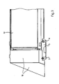
- FIG. 3 a rear view of a mounting system 1 with arranged photovoltaic elements 2 in the end region of a line-shaped arrangement 9 is shown.
- the elastic locking element 5 is in positive engagement with the profile structure 6 of the floor rail profile 3 and forms a clamping in the manner of fixing in the floor rail profile 3.
- the mounting system 1 is covered by front (not shown here), side and rear cover 10,11 and 12, wherein the side cover 10 each arranged in the end of the line 9 photovoltaic Elements 2 is mounted in the mounting system 1.
- the attachment of the cover elements 10, 11, 12 is carried out by means of corresponding fastening elements (not shown here). Moreover, the mounting system 1 is formed such that the side, front and rear cover members 10, 11, 12 can be fixed to each photovoltaic element 2.
- FIG. 4 shows the mounting system 1 according to the invention, wherein arranged in the foot region of the module support 4, 4a locking element 5 is U-shaped and two, in the longitudinal direction of the bottom rail profile 3 successive locking legs 14a, 14b comprises.
- the latching limb 14a, 14b has a downwardly open recess 16, which can be used for the passage of electrical lines for connecting the photovoltaic elements 2.
- the module support 4, 4a can be inserted from above into the floor rail profile 3, wherein the two locking legs 14a, 14b with the latching legs 14a, 14b formed locking projections 15a, 15b, the profile structure of the bottom rail profile 36 engages behind a positive fit.
- the module support 4, 4a there is a positive and non-positive locking of the module support 4, 4a in the floor rail profile 3, since the locking legs 14a, 14b presses the lateral legs of the bottom rail profile 3 partially outwardly and this braced.
- the module support member 4, 4a are first introduced with the locking leg 14b from above into the bottom rail section 3 and are fixed by pressing the second locking leg 14a positive and non-positive.
- a fastening-free mounting system 1 is formed, which can be set up due to its stable construction without additional loads, such as pebble beds or the like on a roof of a house with low inclination or on a flat roof of a house.
Applications Claiming Priority (1)
| Application Number | Priority Date | Filing Date | Title |
|---|---|---|---|
| DE102008052662A DE102008052662A1 (de) | 2008-10-22 | 2008-10-22 | Montagesystem |
Publications (2)
| Publication Number | Publication Date |
|---|---|
| EP2182303A2 true EP2182303A2 (fr) | 2010-05-05 |
| EP2182303A3 EP2182303A3 (fr) | 2011-03-30 |
Family
ID=41571112
Family Applications (1)
| Application Number | Title | Priority Date | Filing Date |
|---|---|---|---|
| EP09013292A Ceased EP2182303A3 (fr) | 2008-10-22 | 2009-10-21 | Système de montage |
Country Status (2)
| Country | Link |
|---|---|
| EP (1) | EP2182303A3 (fr) |
| DE (2) | DE102008052662A1 (fr) |
Cited By (9)
| Publication number | Priority date | Publication date | Assignee | Title |
|---|---|---|---|---|
| EP2362161A1 (fr) * | 2010-02-22 | 2011-08-31 | B&L | Système de montage de panneaux |
| DE102010017705A1 (de) | 2010-07-02 | 2012-01-05 | Patrik Diwald | Montagevorrichtung zur Anordnung von Solarmodulen |
| JP2012087560A (ja) * | 2010-10-21 | 2012-05-10 | Nihon Form Service Co Ltd | 太陽光発電モジュール用架台システム |
| JP2012097439A (ja) * | 2010-11-01 | 2012-05-24 | Nihon Form Service Co Ltd | 太陽光発電モジュール用架台カバー |
| WO2012095195A3 (fr) * | 2011-01-12 | 2013-04-25 | Fischer Lichtsysteme Gmbh | Système de montage pour une installation solaire et installation solaire pourvue d'un tel système |
| WO2013120678A1 (fr) * | 2012-02-13 | 2013-08-22 | Ilzhoefer Werner | Dispositif de support pour au moins un module solaire |
| EP2813783A1 (fr) * | 2013-06-12 | 2014-12-17 | HILTI Aktiengesellschaft | Support pour soutenir des panneaux solaires sur un toit plat |
| DE102014106800A1 (de) * | 2014-02-26 | 2015-08-27 | Eisenwerk Wittigsthal Gmbh | Ständeranordnung für ein Solarpaneel |
| US20150349700A1 (en) * | 2013-02-11 | 2015-12-03 | Jonathan Port | Modular strap mount for solar panels |
Families Citing this family (11)
| Publication number | Priority date | Publication date | Assignee | Title |
|---|---|---|---|---|
| DE102010022387A1 (de) * | 2010-06-01 | 2011-12-01 | Jürgen Ulrich | Flachdach-Solareinheit |
| DE102010042819A1 (de) * | 2010-06-24 | 2011-12-29 | Inventux Technologies Ag | Solarmodulanordnung mit zwei winklig zueinander angeordneten Solarmodulen |
| DE202010008421U1 (de) * | 2010-09-01 | 2011-12-05 | Egner Gmbh | Tragsystem für Solarmodule |
| DE202010008691U1 (de) | 2010-10-01 | 2011-11-02 | Franz Marschall | Montagesystem zur Befestigung von Photovoltaik-Anlagen auf insbesondere flachen Dächern |
| DE102010047119A1 (de) * | 2010-10-03 | 2012-04-19 | Uwe Wiemann Gmbh & Co. Kg | Traggerüst für schräg zur Horizontalebene angeordnete Solarpaneele |
| DE202010013104U1 (de) * | 2010-12-13 | 2012-03-14 | Stork Beschlagtechnik Gmbh & Co. Kg | Bausatz für Solarmodulträger |
| DE102012007060B8 (de) | 2012-04-02 | 2013-11-28 | Creotecc Gmbh | Montagesystem zum Aufstellen von Photovoltaik-Modulen in einer Ost-West-Ausrichtung |
| DE102012025601B4 (de) | 2012-04-02 | 2013-10-31 | Creotecc Gmbh | Montagesystem zum Aufstellen eines Photovoltaik-Moduls in einer Süd-Ausrichtung oder in einer Ost-West-Ausrichtung |
| DE202012101346U1 (de) * | 2012-04-13 | 2013-07-15 | Richard Brink Gmbh & Co. Kg | Bausatz einer Halteeinrichtung für Solarelemente |
| DE202013103076U1 (de) | 2013-07-11 | 2013-08-07 | Fischer Licht & Metall Gmbh & Co. Kg | Plattenmodulanordnung |
| DE102022111700A1 (de) | 2022-05-10 | 2023-11-16 | Premium Mounting Technologies GmbH & Co. KG | Montagesystem zur Montage von Photovoltaikmodulen auf Dächern |
Citations (7)
| Publication number | Priority date | Publication date | Assignee | Title |
|---|---|---|---|---|
| JP2000064523A (ja) * | 1998-08-19 | 2000-02-29 | Misawa Homes Co Ltd | 太陽電池パネルの設置装置 |
| EP1070923A2 (fr) * | 1999-07-19 | 2001-01-24 | RegEn Energiesysteme GmbH | Dispositif pour la fixation de modules solaires |
| DE20301389U1 (de) | 2003-01-29 | 2004-03-04 | Fa. Oskar Braunsberger | Solarzellenkonsole |
| EP1496550A2 (fr) * | 2003-07-11 | 2005-01-12 | SCHÜCO International KG | Système de montage pour des modules de photovoltaique |
| DE202006018426U1 (de) * | 2006-12-04 | 2007-02-08 | Ideematec Deutschland Gmbh | Montageschienensystem |
| DE202008000997U1 (de) * | 2008-01-23 | 2008-05-15 | Solarpower Gmbh | Befestigungssystem |
| WO2008105296A1 (fr) * | 2007-02-28 | 2008-09-04 | Sharp Kabushiki Kaisha | Structure de fixation d'un module de cellule solaire |
Family Cites Families (11)
| Publication number | Priority date | Publication date | Assignee | Title |
|---|---|---|---|---|
| GB9820133D0 (en) * | 1998-09-16 | 1998-11-11 | Reardon Martin | Guagemaster roof system |
| EP1306907A1 (fr) * | 2001-10-29 | 2003-05-02 | BP Solar Espana, S.A. | Système de montage à ballast réduit |
| DE20204148U1 (de) * | 2002-03-15 | 2002-05-16 | Schueco Int Kg | Vorrichtung zur Montage eines Kollektors und Kollektor |
| DE102005033780A1 (de) * | 2004-07-21 | 2006-03-16 | Goldbeck Solar Gmbh | Vorrichtung zum Befestigen von Funktionsgruppen auf Flachdächern, insbesondere von Solarmodulen auf Industriehallen |
| DE202004015811U1 (de) * | 2004-10-13 | 2004-12-16 | Bbt Thermotechnik Gmbh | Befestigungsvorrichtung für mindestens einen Sonnenkollektor |
| DE102005030039A1 (de) * | 2005-06-27 | 2007-01-11 | Magass, Walter | Leichtbauunterkonstruktion zur Montage von Photovoltaikmodulen auf Flachdächern ohne zusätzliche Auflast |
| EP1969640B1 (fr) * | 2005-12-28 | 2017-08-23 | SunPower Corporation, Systems | Ensemble module photovoltaique (pv) supporté |
| WO2007076519A2 (fr) * | 2005-12-29 | 2007-07-05 | Sunpower Corporation, Systems | Ensemble photovoltaique pliant monobloc |
| DE102007023177A1 (de) * | 2006-06-24 | 2008-03-27 | Könsen, Sven | Unterkonstruktion für PV-Anlage |
| EP1947402A1 (fr) * | 2007-01-18 | 2008-07-23 | Aplisun Develop, S.L. | Cadre de support pour panneaux solaires |
| DE202008000528U1 (de) * | 2008-01-11 | 2008-03-20 | Metzger, Herbert H. W. | Solarmodulanordnung |
-
2008
- 2008-10-22 DE DE102008052662A patent/DE102008052662A1/de not_active Withdrawn
-
2009
- 2009-10-21 EP EP09013292A patent/EP2182303A3/fr not_active Ceased
- 2009-10-21 DE DE202009018534U patent/DE202009018534U1/de not_active Expired - Lifetime
Patent Citations (7)
| Publication number | Priority date | Publication date | Assignee | Title |
|---|---|---|---|---|
| JP2000064523A (ja) * | 1998-08-19 | 2000-02-29 | Misawa Homes Co Ltd | 太陽電池パネルの設置装置 |
| EP1070923A2 (fr) * | 1999-07-19 | 2001-01-24 | RegEn Energiesysteme GmbH | Dispositif pour la fixation de modules solaires |
| DE20301389U1 (de) | 2003-01-29 | 2004-03-04 | Fa. Oskar Braunsberger | Solarzellenkonsole |
| EP1496550A2 (fr) * | 2003-07-11 | 2005-01-12 | SCHÜCO International KG | Système de montage pour des modules de photovoltaique |
| DE202006018426U1 (de) * | 2006-12-04 | 2007-02-08 | Ideematec Deutschland Gmbh | Montageschienensystem |
| WO2008105296A1 (fr) * | 2007-02-28 | 2008-09-04 | Sharp Kabushiki Kaisha | Structure de fixation d'un module de cellule solaire |
| DE202008000997U1 (de) * | 2008-01-23 | 2008-05-15 | Solarpower Gmbh | Befestigungssystem |
Cited By (16)
| Publication number | Priority date | Publication date | Assignee | Title |
|---|---|---|---|---|
| EP2362161A1 (fr) * | 2010-02-22 | 2011-08-31 | B&L | Système de montage de panneaux |
| WO2011101470A3 (fr) * | 2010-02-22 | 2011-12-01 | B&L | Système de montage de panneaux |
| BE1019082A5 (nl) * | 2010-02-22 | 2012-02-07 | B & L | Paneelmontagesysteem. |
| DE102010017705A1 (de) | 2010-07-02 | 2012-01-05 | Patrik Diwald | Montagevorrichtung zur Anordnung von Solarmodulen |
| JP2012087560A (ja) * | 2010-10-21 | 2012-05-10 | Nihon Form Service Co Ltd | 太陽光発電モジュール用架台システム |
| JP2012097439A (ja) * | 2010-11-01 | 2012-05-24 | Nihon Form Service Co Ltd | 太陽光発電モジュール用架台カバー |
| WO2012095195A3 (fr) * | 2011-01-12 | 2013-04-25 | Fischer Lichtsysteme Gmbh | Système de montage pour une installation solaire et installation solaire pourvue d'un tel système |
| WO2013120678A1 (fr) * | 2012-02-13 | 2013-08-22 | Ilzhoefer Werner | Dispositif de support pour au moins un module solaire |
| US9312414B2 (en) | 2012-02-13 | 2016-04-12 | Werner Ilzhoefer | Device for supporting at least one solar panel |
| US20150349700A1 (en) * | 2013-02-11 | 2015-12-03 | Jonathan Port | Modular strap mount for solar panels |
| US9742347B2 (en) * | 2013-02-11 | 2017-08-22 | Jonathan Port | Modular strap mount for solar panels |
| US9985574B2 (en) * | 2013-02-11 | 2018-05-29 | Jonathan Port | Modular strap mount for solar panels |
| US9194612B2 (en) | 2013-06-12 | 2015-11-24 | Hilti Aktiengesellschaft | Stand for supporting solar panels on a flat roof |
| EP2813783A1 (fr) * | 2013-06-12 | 2014-12-17 | HILTI Aktiengesellschaft | Support pour soutenir des panneaux solaires sur un toit plat |
| DE102014106800B4 (de) * | 2014-02-26 | 2015-11-12 | Eisenwerk Wittigsthal Gmbh | Ständeranordnung für ein Solarpaneel |
| DE102014106800A1 (de) * | 2014-02-26 | 2015-08-27 | Eisenwerk Wittigsthal Gmbh | Ständeranordnung für ein Solarpaneel |
Also Published As
| Publication number | Publication date |
|---|---|
| DE102008052662A1 (de) | 2010-05-27 |
| EP2182303A3 (fr) | 2011-03-30 |
| DE202009018534U1 (de) | 2012-02-09 |
Similar Documents
| Publication | Publication Date | Title |
|---|---|---|
| EP2182303A2 (fr) | Système de montage | |
| DE202005006951U1 (de) | Montagesystem und Montageschiene für Dachzubehörelemente, insbesondere für Photovoltaikelemente und/oder Solarkollektoren | |
| DE102012209395A1 (de) | Stützfuß zur Einleitung und Verteilung von Kräften auf einen drucksensiblen Untergrund sowie Ständersystem mit einem solchen Stützfuß | |
| DE202005003750U1 (de) | Trägerkonstruktion für Solarmodule | |
| EP2669451A2 (fr) | Structure porteuse et procédé de montage d'une structure porteuse | |
| DE202015102936U1 (de) | Photovoltaikmodul-Montagebügel sowie Photovoltaiksystem | |
| DE202010018095U1 (de) | Vorrichtung zur Befestigung mindestens eines Solarmoduls | |
| DE202009015122U1 (de) | Vorrichtung zum Abstützen von Solarmodulen | |
| EP3715561B1 (fr) | Système de toiture et module de support associé | |
| DE202016006723U1 (de) | Aufständerung zur Überdachung von Flächen, insbesondere Carport | |
| DE202006013662U1 (de) | Aufnahmeelement für Photovoltaikmodule auf Flachdächern | |
| EP2248504B1 (fr) | Unité d'alimentation médicale dotée de modules encastrables | |
| EP2378563A2 (fr) | Système de montage pour module solaire | |
| EP1439278B1 (fr) | Joint automatique pour portes avec support adjustable | |
| DE102012016797B4 (de) | Dachunterbau in Zickzackform | |
| DE102011007521A1 (de) | Unterkonstruktion für eine Solarmodul-Freilandanordnung | |
| EP2378221A2 (fr) | Système de montage pour modules solaires et procédé de montage d'une installation solaire | |
| EP2423622B1 (fr) | Dispositif de fixation avec éléments de montage et rail de support | |
| DE102009051756A1 (de) | Montagesystem für die Aufständerung von Solarmodulen | |
| DE202008014066U1 (de) | Riegelelement für eine Dachkonstruktion und Terrassendach | |
| EP2400238B1 (fr) | Elévation d'un module solaire | |
| EP3978825B1 (fr) | Dispositif de support des modules solaires, kit, procédé de fabrication et agencement de module solaire | |
| EP2211122A1 (fr) | Kit de montage destiné à soutenir des modules solaires | |
| DE202013006006U1 (de) | Reihenverbinder für Solarmodule | |
| EP3978827A1 (fr) | Dispositif de support des modules solaires, ensemble, procédé de fabrication et agencement de module solaire |
Legal Events
| Date | Code | Title | Description |
|---|---|---|---|
| PUAI | Public reference made under article 153(3) epc to a published international application that has entered the european phase |
Free format text: ORIGINAL CODE: 0009012 |
|
| AK | Designated contracting states |
Kind code of ref document: A2 Designated state(s): AT BE BG CH CY CZ DE DK EE ES FI FR GB GR HR HU IE IS IT LI LT LU LV MC MK MT NL NO PL PT RO SE SI SK SM TR |
|
| AX | Request for extension of the european patent |
Extension state: AL BA RS |
|
| PUAL | Search report despatched |
Free format text: ORIGINAL CODE: 0009013 |
|
| AK | Designated contracting states |
Kind code of ref document: A3 Designated state(s): AT BE BG CH CY CZ DE DK EE ES FI FR GB GR HR HU IE IS IT LI LT LU LV MC MK MT NL NO PL PT RO SE SI SK SM TR |
|
| AX | Request for extension of the european patent |
Extension state: AL BA RS |
|
| 17P | Request for examination filed |
Effective date: 20110901 |
|
| 17Q | First examination report despatched |
Effective date: 20140131 |
|
| RAP1 | Party data changed (applicant data changed or rights of an application transferred) |
Owner name: KNUBIX GMBH |
|
| RAP1 | Party data changed (applicant data changed or rights of an application transferred) |
Owner name: SOLTOP SCHUPPISSER AG |
|
| STAA | Information on the status of an ep patent application or granted ep patent |
Free format text: STATUS: THE APPLICATION HAS BEEN REFUSED |
|
| 18R | Application refused |
Effective date: 20161029 |