EP2182303A2 - Montagesystem - Google Patents
Montagesystem Download PDFInfo
- Publication number
- EP2182303A2 EP2182303A2 EP09013292A EP09013292A EP2182303A2 EP 2182303 A2 EP2182303 A2 EP 2182303A2 EP 09013292 A EP09013292 A EP 09013292A EP 09013292 A EP09013292 A EP 09013292A EP 2182303 A2 EP2182303 A2 EP 2182303A2
- Authority
- EP
- European Patent Office
- Prior art keywords
- elements
- mounting system
- photovoltaic
- arrangement
- rail profile
- Prior art date
- Legal status (The legal status is an assumption and is not a legal conclusion. Google has not performed a legal analysis and makes no representation as to the accuracy of the status listed.)
- Ceased
Links
- 238000009434 installation Methods 0.000 title description 6
- 230000000284 resting effect Effects 0.000 claims description 2
- 210000000078 claw Anatomy 0.000 description 2
- 238000011109 contamination Methods 0.000 description 2
- 230000005855 radiation Effects 0.000 description 2
- 238000005253 cladding Methods 0.000 description 1
- 238000010276 construction Methods 0.000 description 1
- 230000002950 deficient Effects 0.000 description 1
- 230000001419 dependent effect Effects 0.000 description 1
- 238000005553 drilling Methods 0.000 description 1
Images


Classifications
-
- H—ELECTRICITY
- H02—GENERATION; CONVERSION OR DISTRIBUTION OF ELECTRIC POWER
- H02S—GENERATION OF ELECTRIC POWER BY CONVERSION OF INFRARED RADIATION, VISIBLE LIGHT OR ULTRAVIOLET LIGHT, e.g. USING PHOTOVOLTAIC [PV] MODULES
- H02S20/00—Supporting structures for PV modules
- H02S20/20—Supporting structures directly fixed to an immovable object
- H02S20/22—Supporting structures directly fixed to an immovable object specially adapted for buildings
- H02S20/23—Supporting structures directly fixed to an immovable object specially adapted for buildings specially adapted for roof structures
- H02S20/24—Supporting structures directly fixed to an immovable object specially adapted for buildings specially adapted for roof structures specially adapted for flat roofs
-
- F—MECHANICAL ENGINEERING; LIGHTING; HEATING; WEAPONS; BLASTING
- F24—HEATING; RANGES; VENTILATING
- F24S—SOLAR HEAT COLLECTORS; SOLAR HEAT SYSTEMS
- F24S25/00—Arrangement of stationary mountings or supports for solar heat collector modules
- F24S25/10—Arrangement of stationary mountings or supports for solar heat collector modules extending in directions away from a supporting surface
- F24S25/16—Arrangement of interconnected standing structures; Standing structures having separate supporting portions for adjacent modules
-
- F—MECHANICAL ENGINEERING; LIGHTING; HEATING; WEAPONS; BLASTING
- F24—HEATING; RANGES; VENTILATING
- F24S—SOLAR HEAT COLLECTORS; SOLAR HEAT SYSTEMS
- F24S25/00—Arrangement of stationary mountings or supports for solar heat collector modules
- F24S25/60—Fixation means, e.g. fasteners, specially adapted for supporting solar heat collector modules
- F24S25/63—Fixation means, e.g. fasteners, specially adapted for supporting solar heat collector modules for fixing modules or their peripheral frames to supporting elements
- F24S25/634—Clamps; Clips
-
- F—MECHANICAL ENGINEERING; LIGHTING; HEATING; WEAPONS; BLASTING
- F24—HEATING; RANGES; VENTILATING
- F24S—SOLAR HEAT COLLECTORS; SOLAR HEAT SYSTEMS
- F24S25/00—Arrangement of stationary mountings or supports for solar heat collector modules
- F24S25/60—Fixation means, e.g. fasteners, specially adapted for supporting solar heat collector modules
- F24S2025/6004—Fixation means, e.g. fasteners, specially adapted for supporting solar heat collector modules by clipping, e.g. by using snap connectors
-
- Y—GENERAL TAGGING OF NEW TECHNOLOGICAL DEVELOPMENTS; GENERAL TAGGING OF CROSS-SECTIONAL TECHNOLOGIES SPANNING OVER SEVERAL SECTIONS OF THE IPC; TECHNICAL SUBJECTS COVERED BY FORMER USPC CROSS-REFERENCE ART COLLECTIONS [XRACs] AND DIGESTS
- Y02—TECHNOLOGIES OR APPLICATIONS FOR MITIGATION OR ADAPTATION AGAINST CLIMATE CHANGE
- Y02B—CLIMATE CHANGE MITIGATION TECHNOLOGIES RELATED TO BUILDINGS, e.g. HOUSING, HOUSE APPLIANCES OR RELATED END-USER APPLICATIONS
- Y02B10/00—Integration of renewable energy sources in buildings
- Y02B10/10—Photovoltaic [PV]
-
- Y—GENERAL TAGGING OF NEW TECHNOLOGICAL DEVELOPMENTS; GENERAL TAGGING OF CROSS-SECTIONAL TECHNOLOGIES SPANNING OVER SEVERAL SECTIONS OF THE IPC; TECHNICAL SUBJECTS COVERED BY FORMER USPC CROSS-REFERENCE ART COLLECTIONS [XRACs] AND DIGESTS
- Y02—TECHNOLOGIES OR APPLICATIONS FOR MITIGATION OR ADAPTATION AGAINST CLIMATE CHANGE
- Y02B—CLIMATE CHANGE MITIGATION TECHNOLOGIES RELATED TO BUILDINGS, e.g. HOUSING, HOUSE APPLIANCES OR RELATED END-USER APPLICATIONS
- Y02B10/00—Integration of renewable energy sources in buildings
- Y02B10/20—Solar thermal
-
- Y—GENERAL TAGGING OF NEW TECHNOLOGICAL DEVELOPMENTS; GENERAL TAGGING OF CROSS-SECTIONAL TECHNOLOGIES SPANNING OVER SEVERAL SECTIONS OF THE IPC; TECHNICAL SUBJECTS COVERED BY FORMER USPC CROSS-REFERENCE ART COLLECTIONS [XRACs] AND DIGESTS
- Y02—TECHNOLOGIES OR APPLICATIONS FOR MITIGATION OR ADAPTATION AGAINST CLIMATE CHANGE
- Y02E—REDUCTION OF GREENHOUSE GAS [GHG] EMISSIONS, RELATED TO ENERGY GENERATION, TRANSMISSION OR DISTRIBUTION
- Y02E10/00—Energy generation through renewable energy sources
- Y02E10/40—Solar thermal energy, e.g. solar towers
- Y02E10/47—Mountings or tracking
-
- Y—GENERAL TAGGING OF NEW TECHNOLOGICAL DEVELOPMENTS; GENERAL TAGGING OF CROSS-SECTIONAL TECHNOLOGIES SPANNING OVER SEVERAL SECTIONS OF THE IPC; TECHNICAL SUBJECTS COVERED BY FORMER USPC CROSS-REFERENCE ART COLLECTIONS [XRACs] AND DIGESTS
- Y02—TECHNOLOGIES OR APPLICATIONS FOR MITIGATION OR ADAPTATION AGAINST CLIMATE CHANGE
- Y02E—REDUCTION OF GREENHOUSE GAS [GHG] EMISSIONS, RELATED TO ENERGY GENERATION, TRANSMISSION OR DISTRIBUTION
- Y02E10/00—Energy generation through renewable energy sources
- Y02E10/50—Photovoltaic [PV] energy
Definitions
- the invention relates to a mounting system for the arrangement of photovoltaic elements according to the preamble of patent claim 1.
- Mounting systems in particular mounting brackets for modules of photovoltaic systems are known in a variety of different embodiments.
- the arrangement of the photovoltaic system for example on houses with a flat roof or with a sloping roof is an important selection criterion for the mounting system to be used or for the mounting brackets arranged underneath.
- the console is additionally filled with appropriate Auflastungsstoffn, the console can be mounted on the surface of a rooftop or a sloped roof.
- console achieved only in the assembly with a solar cell module and appropriate load or attachment the required overall stability.
- a structure of such a console without a solar cell module and without load or attachment thus forms an insufficient stability.
- the invention has the task of further developing a mounting system for the arrangement of photovoltaic elements such that a cost-effective and simplified installation of photovoltaic elements is made possible.
- the invention is characterized by the features of claim 1.
- the invention is based on a mounting system for arranging photovoltaic elements, in particular on a house roof with low inclination or flat roof, wherein the mounting system rail elements and module support elements comprises, to which the photovoltaic element is fastened by means of fastening elements.
- the essence of the invention is that the resting on a footprint of the house roof rail element is designed as a linearly extending floor rail profile, which by means of elastic locking elements with Modul variancelexnenten is connected.
- the elastic latching elements are latched into the U-shaped bottom rail profile such that an additional attachment of the module support elements is eliminated.
- the latching element may be formed of an elastic plastic, wherein the function-generating profile shape of the latching element is in the foreground in connection with the floor rail profile.
- the elastic latching element is introduced by means of a tilting, rotating or pushing movement in the floor rail profile and engages behind the profile structure of the floor rail profile in the locked state form fit.
- Such an introduction of an elastic locking element in the floor rail profile has the advantage that, for example, a subsequent replacement of module support elements or an arrangement or removal of module support elements can be performed without major installation effort. Likewise, the entrasteten module support elements can be moved in position, and re-engaged after position adjustment and thus fixed.
- the mounting system free of photovoltaic elements, completely self-standing is buildable.
- the necessary module support elements by means of the elastic locking elements are arranged one behind the other in the ground rail profile by positive engagement behind the profile structure self-standing.
- the structure of a completely self-standing mounting system has the advantage that the damage-sensitive photovoltaic elements must be delivered and fixed only at the end of the system structure, for example, an extension or reduction of the mounting system without great installation effort is always feasible.
- the bottom rail element is covered in the longitudinal direction between two arranged module support elements with a cover.
- Covering the floor rail elements has the advantage that the floor rail profile can be kept almost free from contamination for a possible expansion or disassembly of the photovoltaic system.
- a floor rail profile covered with cover elements forms a cable channel-like protection for inlets and outlets of the photovoltaic element, since the floor rail profile can be used in the manner of a duct guide.
- the profile surface lying on the roof surface has recesses on the floor rail profile, which provides an improved outflow of incoming dirt or moisture by, for example, ice, snow or rain.
- the elastic locking element in the floor rail profile is longitudinally displaceable.
- a length-displaceable latching element has the advantage that in the assembly of such a photovoltaic system, the arrangement of the photovoltaic elements is changed at any time.
- photovoltaic elements can be replaced or used by similar elements with altered dimensions later without major installation effort.
- a combined arrangement of photovoltaic elements with different dimensions is also feasible with the mounting system according to the invention.
- Another core of the invention is to provide an arrangement of photovoltaic elements, wherein a mounting system is present, which is completely mountable before the arrangement of a photovoltaic element.
- the mounting system is arranged free of fasteners and / or without load on a house roof.
- the mounting system on additional loads such as a gravel pile or concrete loading in the area of the floor rail profiles for weighting of the entire system or on an attachment of the floor rail profiles on the roof surface omitted.
- additional loads such as a gravel pile or concrete loading in the area of the floor rail profiles for weighting of the entire system or on an attachment of the floor rail profiles on the roof surface omitted.
- an arrangement of a mounting system in which the mounting system forms a row and columnar arrangement of photovoltaic elements, wherein two adjacent photovoltaic elements are arranged along a column on a common rail element.
- the arrangement of two adjacent photovoltaic elements on a common rail element has the advantage that for the attachment of photovoltaic elements, only one front and one rear Modulsttltzelement per floor rail profile is required to secure two photovoltaic elements with their adjacent sides.
- the two module support elements have different lengths in order to form an inclined arrangement of photovoltaic elements.
- the lengths are designed such that a mounted, photovoltaic element has an advantageous inclination of about 30 degrees, which ensures optimum solar radiation to the photovoltaic element.
- the length of the module support elements is variably adjustable.
- the module support element is formed, for example, in a two-part embodiment, wherein the overlapping profile legs each have a recess and an elongated recess, which are connected by a variable length variable element with each other.
- each photovoltaic element is preferably formed with a front, with a rear and in the exposed case with one or two lateral cover elements.
- the arrangement of photovoltaic elements designed in the manner of an "all-round cladding" has the advantage that the arranged covering elements additionally assume the function of wind deflecting surfaces in the event of high wind loads, whereby the risk of lifting the mounting system in connection with the photovoltaic elements is virtually ruled out.
- FIG. 1 a mounting system 1 is shown with photovoltaic elements 2 arranged thereon, wherein the mounting system 1 is to be arranged on a flat roof of a house or on a roof with low inclination.
- the mounting system 1 comprises floor rail profiles 3 which are arranged substantially parallel to one another and are used for the arrangement of module support elements 4, 4a (in FIG FIG. 2 shown in more detail) are formed.
- the photovoltaic elements 2 are connected to corresponding module support elements 4, 4 a, wherein the photovoltaic elements 2 have an inclined arrangement, which is adapted to optimum solar radiation for the photovoltaic elements 2.
- the photovoltaic elements 2 are fastened by means of appropriate fastening means 13 to the module support elements 4, 4a.
- the photovoltaic elements 2 are arranged on the mounting system 1 such that they form a columnar and a line-shaped arrangement 8, 9 on the mounting system 1 with respect to the bottom rail profiles 3.
- the photovoltaic elements 2 form in their line-shaped arrangement 9 an exposed distance on the floor rail profile 3, which is to be covered with corresponding cover elements 7.
- lateral end regions in the line-shaped arrangement 9 of the photovoltaic elements 2 are each covered with lateral cover elements 10, which form an additional protection against lateral wind loads for the mounting system 1.
- FIG. 2 a perspective view of a floor rail profile 3 is shown, wherein the floor rail profile 3 has a U-shaped profile structure 6 with in each case inwardly directed profile legs.
- This profile structure 6 is designed to receive an elastic latching element 5, which forms a positive connection with the profile structure 9 of the module support element 4, 4a.
- the elastic locking element 5 preferably has a rectangular shape, wherein the side surfaces of the elastic locking element 5 of the profile structure 6 of the bottom rail profile 3 is adjusted.
- the elastic locking element 5 is to be introduced by means of a tilting, rotating or pushing movement in the bottom rail profile 3, wherein the elastic locking element 5 performs a clamping function with the profile structure 6 of the bottom rail section 3 due to its outer profile adapted to the floor rail profile 3 and its long dimensions.
- a fastening means-free arrangement of a module support element 4, 4a in the bottom rail section 3 executable.
- the module support element 4, 4a by means of the elastic locking element 5 in the floor rail profile 3 is longitudinally displaceable.
- the Modulsttitzelement 4, 4a is formed for example as an angled profile element, on which on the downwardly directed and angled profile surface, the elastic locking element 5 is arranged.
- module support element 4, 4a in its vertically upwardly directed end region on a further, angled profile surface, which is designed for support and arrangement of a photovoltaic element 2.
- the module support element 4, 4a has different length dimensions, which form a corresponding inclination angle for the photovoltaic element 2 for its arrangement on a house roof.
- the bottom rail profile 3 has an upwardly directed opening which is to be covered by means of a cover element 7.
- This cover member 7 is formed such that, for example, a positive-locking arrangement on the floor rail profile 3 or an arrangement by fastening corresponding fasteners.
- cover member 7 is also to be fastened by means of further, known from the prior art mounting forms on the floor rail profile 3, which are not described here.
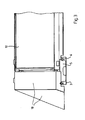
- FIG. 3 a rear view of a mounting system 1 with arranged photovoltaic elements 2 in the end region of a line-shaped arrangement 9 is shown.
- the elastic locking element 5 is in positive engagement with the profile structure 6 of the floor rail profile 3 and forms a clamping in the manner of fixing in the floor rail profile 3.
- the mounting system 1 is covered by front (not shown here), side and rear cover 10,11 and 12, wherein the side cover 10 each arranged in the end of the line 9 photovoltaic Elements 2 is mounted in the mounting system 1.
- the attachment of the cover elements 10, 11, 12 is carried out by means of corresponding fastening elements (not shown here). Moreover, the mounting system 1 is formed such that the side, front and rear cover members 10, 11, 12 can be fixed to each photovoltaic element 2.
- FIG. 4 shows the mounting system 1 according to the invention, wherein arranged in the foot region of the module support 4, 4a locking element 5 is U-shaped and two, in the longitudinal direction of the bottom rail profile 3 successive locking legs 14a, 14b comprises.
- the latching limb 14a, 14b has a downwardly open recess 16, which can be used for the passage of electrical lines for connecting the photovoltaic elements 2.
- the module support 4, 4a can be inserted from above into the floor rail profile 3, wherein the two locking legs 14a, 14b with the latching legs 14a, 14b formed locking projections 15a, 15b, the profile structure of the bottom rail profile 36 engages behind a positive fit.
- the module support 4, 4a there is a positive and non-positive locking of the module support 4, 4a in the floor rail profile 3, since the locking legs 14a, 14b presses the lateral legs of the bottom rail profile 3 partially outwardly and this braced.
- the module support member 4, 4a are first introduced with the locking leg 14b from above into the bottom rail section 3 and are fixed by pressing the second locking leg 14a positive and non-positive.
- a fastening-free mounting system 1 is formed, which can be set up due to its stable construction without additional loads, such as pebble beds or the like on a roof of a house with low inclination or on a flat roof of a house.
Abstract
Description
- Die Erfindung bezieht sich auf ein Montagesystem zur Anordnung photovoltaischer Elemente nach dem Oberbegriff des Patentanspruchs 1.
- Montagesysteme, insbesondere Befestigungskonsolen für Module von Photovoltaikanlagen sind in einer Vielzahl von unterschiedlichen Ausführungsformen bekannt. Dabei ist die Anordnung der Photovoltaikanlage beispielsweise auf Häusern mit einem Flachdach oder mit einem geneigten Dach ein wichtiges Auswahlkriterium für das zu verwendende Montagesystem bzw. für die darunter angeordneten Befestigungskonsolen.
- In der Druckschrift
DE 203 01 389 U1 ist eine Konsole in Form einer Wanne zur Befestigung von Solarzellen gezeigt, wobei das Solarzellenmodul mittels Klauen auf der Konsole mit einer vorgegebenen Neigung befestigt ist. - Für eine erforderliche Standsicherheit wird die Konsole zusätzlich mit entsprechenden Auflastungsmitteln befüllt, wobei die Konsole auf der Oberfläche eines Hausdachs bzw. eines geneigten Dachs befestigt werden kann.
- Dadurch erreicht die Konsole erreicht lediglich im zusammenbau mit einem Solarzellenmodul und entsprechender Auflastung bzw. Befestigung die erforderliche Gesamtstabilität.
- Ein Aufbau einer derartigen Konsole ohne ein Solarzellenmodul und ohne Auflastung bzw. Befestigung bildet somit eine nicht ausreichende Stabilität.
- Darüber hinaus ist beispielsweise ein Auswechseln eines derartigen Konsolenelements bzw. eine Erweiterung oder Reduzierung der Anlage mit einem erheblichen Montageaufwand verbunden.
- Aus diesem Grunde hat sich die Erfindung die Aufgabe gestellt, ein Montagesystem zur Anordnung von photovoltaischen Elementen derart weiterzubilden, dass eine kostengünstige und vereinfache Montage von photovoltaischen Elementen ermöglicht wird.
- Zur Lösung der Aufgabe ist die Erfindung durch die Merkmale des Patentanspruchs 1 gekennzeichnet.
- Vorteilhafte Erweiterungen der Erfindung sind in den abhängigen Ansprüchen beschrieben.
- Die Erfindung geht von einem Montagesystem zur Anordnung photovoltaischer Elemente aus, insbesondere auf einem Hausdach mit geringer Neigung oder Flachdach, wobei das Montagesystem Schienenelemente und Modulstützelemente umfasst, an welchen das photovoltaische Element mittels Befestigungselementen befestigt ist.
- Der Kern der Erfindung liegt darin, dass das auf einer Aufstellfläche des Hausdaches aufliegende Schienenelement als ein linear verlaufendes Bodenschienenprofil ausgebildet ist, welches mittels elastischen Rastelementen mit Modulstützelexnenten verbunden ist.
- Durch das linear verlaufende Bodenschienenprofil ist eine Anordnung von Modulstützelementen an jeder beliebigen Stelle des Bodenschienenprofils möglich.
- Darüber hinaus ist es vorteilhaft, dass die elastischen Rastelemente in das U-förmig ausgebildete Bodenschienenprofil derart einrastbar sind, dass eine zusätzliche Befestigung der Modulstützelemente entfällt.
- Erfindungsgemäß kann das Rastelement aus einem elastischen Kunststoff gebildet sein, wobei die funktionserzeugende Profilform des Rastelements in Verbindung mit dem Bodenschienenprofil im Vordergrund steht.
- In einer bevorzugten Ausgestaltung der Erfindung ist es vorgesehen, dass das elastische Rastelement mittels einer Kipp-, Dreh- oder Drückbewegung in das Bodenschienenprofil einzubringen ist und im verrasteten Zustand die Profilstruktur des Bodenschienenprofils formschlüssig hintergreift.
- Ein derartiges Einbringen eines elastischen Rastelementes in das Bodenschienenprofil hat den Vorteil, dass beispielsweise ein nachträgliches Austauschen von Modulstützelementen bzw. eine Anordnung oder Entnahme von Modulstützelementen ohne größeren Montageaufwand durchgeführt werden kann. Ebenso können die entrasteten Modulstützelemente in ihrer Position verschoben werden, und nach erfolgter Positionsjustage erneut eingerastet und somit fixiert werden.
- Durch das formschlüssige Hintergreifen des Rastelementes im Bodenschienenprofil wird eine Verbindung gebildet, die auf ein zusätzliches Verbinden der Modulstützelemente mit dem Bodenschienenprofil nicht erfordert.
- In einer überdies bevorzugten Ausgestaltung der Erfindung ist es vorgesehen, dass das Montagesystem frei von photovoltaischen Elementen, vollständig selbststehend aufbaubar ist.
- Dabei werden die notwendigen Modulstützelemente mittels der elastischen Rastelemente hintereinander in das Bodenschienenprofil durch formschlüssiges Hintergreifen der Profilstruktur selbststehend angeordnet.
- Der Aufbau eines vollständig selbststehenden Montagesystems weist den Vorteil auf, dass die beschädigungsempfindlichen photovoltaischen Elemente erst zum Ende des Anlagenaufbaus angeliefert und befestigt werden müssen, wobei beispielsweise eine Erweiterung bzw. Verkleinerung des Montagesystems ohne großen Montageaufwand jederzeit durchführbar ist.
- Überdies ist es in einer weiteren Ausgestaltung der Erfindung vorgesehen, dass das Bodenschienenelement in Längsrichtung zwischen zwei angeordneten Modulstützelementen mit einem Abdeckelement abgedeckt ist.
- Ein Abdecken der Bodenschienenelemente hat den Vorteil, dass das Bodenschienenprofil nahezu frei von Verschmutzungen für eine eventuelle Erweiterung oder Demontage der photovoltaischen Anlage gehalten werden kann.
- Zusätzlich bildet ein mit Abdeckelementen abgedecktes Bodenschienenprofil einen kabelkanalartigen Schutz für Zu- bzw. Ableitungen des photovoltaischen Elements, da das Bodenschienenprofil in der Art einer Kanalführung verwendbar ist.
- Vorteilhafterweise weist die auf der Dachoberfläche liegende Profilfläche das Bodenschienenprofils Ausnehmungen auf, welche einen verbesserten Abfluss von eintretenden Verschmutzungen bzw. Feuchtigkeit durch beispielsweise Eis, Schnee oder Regen bereitstellt.
- In einer weiteren bevorzugten Ausgestaltung der Erfindung ist es vorgesehen, dass das elastische Rastelement im Bodenschienenprofil längsverschiebbar ist.
- Ein längenverschiebbares Rastelement hat den Vorteil, dass bei der Montage einer derartigen photovoltaischen Anlage die Anordnung der photovoltaischen Elemente jederzeit veränderbar ist.
- Darüber hinaus ist es denkbar, dass photovoltaische Elemente durch ähnliche Elemente mit veränderten Abmessungen nachträglich ohne größeren Montageaufwand ersetzt bzw. eingesetzt werden können. Eine kombinierte Anordnung von photovoltaischen Elementen mit unterschiedlichen Abmessungen ist ebenfalls mit dem erfindungsgemäßen Montagesystem durchführbar.
- Ein weiterer Kern der Erfindung liegt darin, eine Anordnung photovoltaischer Elemente vorzusehen, wobei ein Montagesystem vorhanden ist, welches vor Anordnung eines photovoltaischen Elements vollständig montierbar ist.
- Dies hat den Vorteil, dass eine Beschädigung von oftmals teuren photovoltaischen Elementen auf ein Minimum reduziert werden kann, da die photovoltaischen Elemente erst nach Fertigstellung des gesamten Montagesystems auf den Modulstützelementen sicher montiert werden.
- In einer weiteren Ausgestaltung der Erfindung zur Anordnung eines Montagesystems ist vorgesehen, dass das Montagesystem befestigungsmittelfrei und/oder auflastungsfrei an einem Hausdach angeordnet ist.
- Aufgrund des modulartigen Aufbaus des Montagesystems ohne zusätzliche Befestigungsmittel sind eine Montage/Demontage der Gesamtanlage bzw. eine Verkleinerung oder Erweiterung der Anlage sowie der Austausch von beispielsweise defekten photovoltaischen Elementen jederzeit möglich.
- Zusätzlich ist es vorteilhaft, dass das Montagesystem auf zusätzliche Auflastungen, wie beispielsweise eine Kiesaufschüttung oder Betonauflastung im Bereich der Bodenschienenprofile zur Beschwerung der Gesamtanlage bzw. auf eine Befestigung der Bodenschienenprofile auf der Dachoberfläche verzichtet. Hierdurch wird beispielsweise eine kurzzeitige Änderung von Teilbereichen der Anlage oder der Gesamtanlage ermöglicht und es werden Dachbeschädigungen durch Bohrungen vermieden.
- In einer überdies bevorzugten Ausgestaltung der Erfindung ist eine Anordnung eines Montagesystems vorgesehen, in welcher das Montagesystem eine zeilen- und spaltenförmige Anordnung von photovoltaischen Elementen ausbildet, wobei zwei benachbarte photovoltaische Elemente entlang einer Spalte auf einem gemeinsamen Schienenelement angeordnet sind.
- Die Anordnung zweier benachbarter photovoltaischer Elemente auf einem gemeinsamen Schienenelement hat den vorteil, dass zur Befestigung von photovoltaischen Elementen lediglich ein vorderes und eine hinteres Modulsttltzelement pro Bodenschienenprofil erforderlich ist, um zwei photovoltaische Elemente mit ihren aneinander grenzenden Seiten zu befestigen.
- Bei der Montage von photovoltaischen Elementen in einem erfindungsgemäßen Montagesystem ist vorzugsweise vorgesehen, dass die beiden Modulstützelemente unterschiedliche Längen aufweisen, um eine geneigte Anordnung von photovoltaischen Elementen auszubilden.
- Dabei sind die Längen derart ausgebildet, dass ein montiertes, photovoltaisches Element eine vorteilhafte Neigung von ca. 30 Grad aufweist, welche eine optimale Sonneneinstrahlung auf das photovoltaische Element gewährleistet.
- Es ist denkbar, dass die Länge der Modulstützelemente variabel einstellbar ist. Hierzu wird das Modulstützelement beispielsweise in einer zweigeteilten Ausführungsform gebildet, wobei die sich überlappenden Profilschenkel jeweils eine Ausnehmung und eine länglich verlaufende Ausnehmung aufweisen, die mittels eines Befestigungselements längenvariabel miteinander verbunden werden.
- In einer überdies bevorzugten Ausgestaltung der Erfindung ist eine Anordnung eines Montagesystems vorgesehen, wobei jedes photovoltaische Element vorzugsweise mit einem vorderen, mit einem hinteren und im freiliegenden Fall mit einem oder zwei seitlichen Abdeckelementen ausgebildet ist.
- Die in der Art einer "Rundum-Verkleidung" ausgebildete Anordnung von photovoltaischen Elementen hat den Vorteil, dass die angeordneten Abdeckelemente bei hohen Windlasten zusätzlich die Funktion von Windleitflächen übernehmen, wodurch die Gefahr eines Abhebens des Montagesystem in Verbindung mit den photovoltaischen Elementen nahezu ausgeschlossen wird.
- Die Anordnung von photovoltaischen Elementen mit dem erfindungsgemäßen Montagesystem auf einem Hausdach mit geringer Neigung oder Flachdach ist befestigungsfrei und ohne zusätzliche Auflastung durchführbar.
- Weitere Vorteile und Einzelheiten gehen aus den dargestellten Zeichnungen hervor und werden nachstehend näher erläutert. Dabei zeigen:
- Figur 1
- eine perspektivische Ansicht eines Montagesystems mit angeordneten photovoltaischen Elementen;
- Figur 2
- eine perspektivische Ansicht eines Bodenschienenprofils mit daran angeordneten Modulstützelementen;
- Figur 3
- eine Rückansicht eines Montagesystems mit angeordneten Abdeckelementen;
- Figur 4
- eine perspektivische Ansicht eines Modulstützelementes mit U-förmigen Rastelement
- In
Figur 1 ist ein Montagesystem 1 mit daran angeordneten photovoltaischen Elementen 2 gezeigt, wobei das Montagesystem 1 auf einem Flachdach eines Hauses bzw. auf einem Dach mit geringer Neigung anzuordnen ist. - Das Montagesystem 1 umfasst im Wesentlichen parallel zueinander angeordnete Bodenschienenprofile 3, die zur Anordnung von Modulstützelementen 4, 4a (in
Figur 2 näher dargestellt) ausgebildet sind. - Die photovoltaischen Elemente 2 sind mit entsprechenden Modulstützelementen 4, 4a verbunden, wobei die photovoltaischen Elemente 2 eine geneigte Anordnung aufweisen, die einer optimalen Sonneneinstrahlung für die photovoltaischen Elemente 2 angepasst ist.
- Die photovoltaischen Elemente 2 sind mittels entsprechender Befestigungsmittel 13 an den Modulstützelementen 4, 4a befestigt.
- Die photovoltaischen Elemente 2 sind auf dem Montagesystem 1 derart angeordnet, dass diese mit Bezug auf die Bodenschienenprofile 3 eine spaltenförmige sowie eine zeilenförmige Anordnung 8, 9 auf dem Montagesystem 1 bilden.
- Die photovoltaischen Elemente 2 bilden in ihrer zeilenförmigen Anordnung 9 einen freiliegenden Abstand auf dem Bodenschienenprofil 3 aus, welcher mit entsprechenden Abdeckelementen 7 abzudecken ist.
- Diese Abdeckelemente 7 bilden einen Schutz gegen Verschmutzungen für die Bodenschienenprofile 3 aus.
- Darüber hinaus sind die seitlichen Endbereiche in der zeilenförmigen Anordnung 9 der photovoltaischen Elemente 2 jeweils mit seitlichen Abdeckelementen 10 abgedeckt, welche einen zusätzlichen Schutz gegen seitliche Windlasten für das Montagesystem 1 bilden.
- In
Figur 2 ist eine perspektivische Ansicht eines Bodenschienenprofils 3 gezeigt, wobei das Bodenschienenprofil 3 eine u-förmige Profilstruktur 6 mit jeweils nach innen gerichteten Profilschenkeln aufweist. - Diese Profilstruktur 6 ist zur Aufnahme eines elastischen Rastelementes 5 ausgebildet, welches eine formschlüssige Verbindung mit der Profilstruktur 9 des Modulstützelements 4, 4a bildet.
- Das elastische Rastelement 5 weist vorzugsweise eine Rechteckform auf, wobei die Seitenflächen des elastischen Rastelements 5 der Profilstruktur 6 des Bodenschienenprofils 3 angepasst ist.
- Das elastische Rastelement 5 ist mittels einer Kipp-, Dreh-oder Drückbewegung in das Bodenschienenprofil 3 einzubringen, wobei das elastische Rastelement 5 aufgrund seines dem Bodenschienenprofil 3 angepassten Außenprofils und seiner Langenabmessungen eine klemmende Funktion mit der Profilstruktur 6 des Bodenschienenprofils 3 ausführt. Hierdurch ist eine befestigungsmittelfreie Anordnung eines Modulstützelementes 4, 4a in dem Bodenschienenprofil 3 ausführbar.
- Durch eine entsprechende Kipp- bzw. Drehbewegung ist das Modulstützelement 4, 4a mittels des elastischen Rastelements 5 in dem Bodenschienenprofil 3 längenverschiebbar. Das Modulsttitzelement 4, 4a ist beispielsweise als abgewinkeltes Profilelement ausgebildet, an welchem an der nach unten gerichteten und abgewinkelten Profilfläche das elastische Rastelement 5 angeordnet ist.
- Zusätzlich weist das Modulstützelement 4, 4a in seinem vertikal nach oben gerichteten Endbereich eine weitere, abgewinkelte profilfläche auf, welche zur Auflage und Anordnung eines photovoltaischen Elements 2 ausgebildet ist.
- Die Befestigung des photovoltaischen Elements 2 auf dem Modulstützelement 4, 4a erfolgt mittels entsprechender Befestigungsmittel 13, die beispielsweise in der Art einer Kralle über ein entsprechendes Befestigungselement in einer angeordneten Ausnehmung auf der abgewinkelten Profilfläche des Modulstützelementes 4, 4a befestigt ist.
- Das Modulstützelement 4, 4a weist unterschiedliche Längenabmessungen auf, welche für das photovoltaische Element 2 einen entsprechenden Neigungswinkel für dessen Anordnung auf einem Hausdach ausbilden.
- Zwischen den einzelnen, zeilenförmigen Anordnungen 9 der photovoltaischen Elemente 2 weist das Bodenschienenprofil 3 eine nach oben gerichtete Öffnung auf, welche mittels eines Abdeckelements 7 abzudecken ist.
- Dieses Abdeckelement 7 ist derart ausgebildet, dass beispielsweise eine formschlüssige Anordnung auf dem Bodenschienenprofil 3 oder eine Anordnung durch Befestigung entsprechender Befestigungselemente erfolgt.
- Darüber hinaus ist das Abdeckelement 7 ebenfalls mittels weiterer, aus dem Stand der Technik bekannten Befestigungsformen auf dem Bodenschienenprofil 3 zu befestigen, welche hier nicht näher beschrieben sind.
- In
Figur 3 ist eine rückwärtige Ansicht eines Montagesystems 1 mit angeordneten photovoltaischen Elementen 2 im Endbereich einer zeilenförmigen Anordnung 9 gezeigt. - Das elastische Rastelement 5 steht im formschlüssigen Eingriff mit der Profilstruktur 6 des Bodenschienenprofils 3 und bildet eine in der Art klemmende Befestigung im Bodenschienenprofil 3 aus.
- Zum Schutz gegen eventuelle Windlasten sowie Verschmutzungen ist das Montagesystem 1 durch vordere (hier nicht dargestellt), seitliche und hintere Abdeckelemente 10,11 und 12 abgedeckt, wobei das seitliche Abdeckelement 10 jeweils im Endbereich der zeilenförmig 9 angeordneten photovoltaischen Elemente 2 im Montagesystem 1 befestigt ist.
- Die Befestigung der Abdeckelemente 10, 11, 12 wird mittels entsprechender Befestigungselemente (hier nicht näher dargestellt) ausgeführt.
Darüber hinaus ist das Montagesystem 1 derart ausgebildet, dass die seitlichen, vorderen und hinteren Abdeckelemente 10, 11, 12 an jedem photovoltaischen Element 2 befestigt werden können. - Die
Figur 4 zeigt das erfindungsgemäße Montagesystem 1, wobei das im Fußbereich der Modulstütze 4, 4a angeordnete Rastelement 5 U-förmig ausgebildet ist und zwei, in Längsrichtung des Bodenschienenprofils 3 hintereinander liegende Rastschenkel 14a, 14b umfasst. Der Rastschenkel 14a, 14b weist eine nach unten offene Ausnehmung 16 auf, die zur Durchführung von elektrischen Leitungen zum Anschluss der photovoltaischen Elemente 2 verwendbar ist. Die Modulstütze 4, 4a kann von oben in das Bodenschienenprofil 3 eingesetzt werden, wobei die beiden Rastschenkel 14a, 14b mit seitlich an den Rastschenkeln 14a, 14b ausgebildeten Rastvorsprüngen 15a, 15b die Profilstruktur des Bodenschienenprofils 36 formschlüssig hintergreift. Es erfolgt eine form- und kraftschlüssige Verrastung der Modulstütze 4, 4a in dem Bodenschienenprofil 3, da der Rastschenkel 14a, 14b die seitlichen Schenkel des Bodenschienenprofils 3 teilweise nach außen drückt und dieses verspannt. Beispielsweise kann das Modulstützelement 4, 4a zuerst mit dem Rastschenkel 14b von oben in das Bodenschienenprofil 3 eingeführt werden und durch Eindrücken des zweiten Rastschenkels 14a form- und kraftschlüssig fixiert werden. - Mit dem erfindungsgemäßen Montagesystem 1 wird ein befestigungsfreies Montagesystem 1 gebildet, welches aufgrund seines standsicheren Aufbaus ohne zusätzliche Auflastungen, wie beispielsweise Kiesaufschüttungen oder dergleichen auf einem Dach eines Hauses mit geringer Neigung oder auf einem Flachdach eines Hauses aufstellbar ist.
- Der Erfindungsgegenstand der vorliegenden Erfindung ergibt sich nicht nur aus dem Gegenstand der einzelnen
- Patentansprüche, sondern auch aus der Kombination der einzelnen Patentansprüche untereinander.
- Alle in den Unterlagen einschließlich der Zusammenfassung offenbarten Angaben und Merkmale, insbesondere die in den Zeichnungen dargestellte räumliche Ausbildung, werden als Erfindung wesentlich beansprucht, soweit sie einzeln oder in Kombination gegenüber dem Stand der Technik neu sind.
-
- 1
- Montagesystem
- 2
- photovoltaisches Element
- 3
- Bodenschienenprofil
- 4
- Modulstützelement (Ausleger)
- 4a
- Modulstützelement (Stütze)
- 5
- Rastelement, elastisch
- 6
- Profilstruktur (Bodenschienenprofil)
- 7
- Abdeckelement
- 8
- spaltenförmige Anordnung
- 9
- zeilenförmige Anordnung
- 10
- seitliches Abdeckelement, rechts/links
- 11
- vorderes Abdeckelement
- 12
- hinteres Abdeckelement
- 13
- Befestigungsmittel
- 14a
- Rastschenkel
- 14b
- Rastschenkel
- 15a
- Rastvorsprung
- 15b
- Rastvorsprung
- 16
- Ausnehmung
Claims (9)
- Montagesystem (1) zur Anordnung photovoltaische Elemente (2), insbesondere auf e-inem Hausdach mit geringer Neigung oder Flachdach, wobei das Montagesystem (1) Schienenelemente und Modulstützelemente (4, 4a) umfasst, an welchen das photovoltaische Element (2) mittels Befestigungselementen (13) befestigt ist, dadurch gekennzeichnet, dass das auf einer Aufstellfläche des Hausdaches aufliegende Schienenelement als ein linear verlaufendes Bodenschienenprofil (3) ausgebildet ist, welches mittels elastischen Rastelementen (5) mit den Modulstützelementen (4, 4a) verbunden ist.
- Montagesystem (1) nach Anspruch 1, dadurch gekennzeichnet, dass das elastische Rastelement (5) mittels einer Kipp-, Dreh-oder Drückbewegung in das Bodenschienenprofil (3) einzubringen ist und im verrasteten Zustand die Profilstruktur (6) des Bodenschienenprofils (3) formschlüssig hintergreift.
- Montagesystem (1) nach einem der vorhergehenden Ansprüche, dadurch gekennzeichnet, dass das Montagesystem (1), frei von photovoltaischer Elemente (2), vollständig selbststehend aufbaubar ist.
- Montagesystem (1) nach einem der vorhergehenden Ansprüche, dadurch gekennzeichnet, dass das Bodenschienprofil (3) zwischen zwei angeordneten Modulstützelementen (4, 4a) mit einem Abdeckelement (7) abgedeckt ist.
- Montagesystem (1) nach einem der vorhergehenden Ansprüche, dadurch gekennzeichnet, dass das elastische Rastelement (5) im Bodenschienenprofil (3) längenverschiebbar ist.
- Anordnung photovoltaischer Elemente (2) nach den Ansprüchen 1 bis 5, dadurch gekennzeichnet, dass ein Montagesystem (1) vorhanden ist, welches vor Anordnung eines photovoltaischen Elements (2) vollständig montierbar ist.
- Anordnung nach Anspruch 6, dadurch gekennzeichnet, dass das Montagesystem (1) befestigungsmittelfrei und/oder auflastungsfrei auf einem Hausdach angeordnet ist.
- Anordnung nach Anspruch 7, dadurch gekennzeichnet, dass das Montagesystem (1) eine zeilen- und spaltenförmige Anordnung (8, 9) von photovoltaischen Elementen (2) ausbildet, wobei zwei benachbarte photovoltaische Elemente (2) entlang einer spaltenförmigen Anordnung (8) auf einem gemeinsamen Bodenschienenprofil (3) angeordnet sind.
- Anordnung nach Anspruch 8, dadurch gekennzeichnet, dass vorzugsweise jedes photovoltaische Element (2) mit einem vorderen (11), mit einem hinteren (12) und mit mindestens einem seitlichen Abdeckelement (10) ausgebildet ist.
Applications Claiming Priority (1)
| Application Number | Priority Date | Filing Date | Title |
|---|---|---|---|
| DE102008052662A DE102008052662A1 (de) | 2008-10-22 | 2008-10-22 | Montagesystem |
Publications (2)
| Publication Number | Publication Date |
|---|---|
| EP2182303A2 true EP2182303A2 (de) | 2010-05-05 |
| EP2182303A3 EP2182303A3 (de) | 2011-03-30 |
Family
ID=41571112
Family Applications (1)
| Application Number | Title | Priority Date | Filing Date |
|---|---|---|---|
| EP09013292A Ceased EP2182303A3 (de) | 2008-10-22 | 2009-10-21 | Montagesystem |
Country Status (2)
| Country | Link |
|---|---|
| EP (1) | EP2182303A3 (de) |
| DE (2) | DE102008052662A1 (de) |
Cited By (9)
| Publication number | Priority date | Publication date | Assignee | Title |
|---|---|---|---|---|
| EP2362161A1 (de) * | 2010-02-22 | 2011-08-31 | B&L | Panelmontagesystem |
| DE102010017705A1 (de) | 2010-07-02 | 2012-01-05 | Patrik Diwald | Montagevorrichtung zur Anordnung von Solarmodulen |
| JP2012087560A (ja) * | 2010-10-21 | 2012-05-10 | Nihon Form Service Co Ltd | 太陽光発電モジュール用架台システム |
| JP2012097439A (ja) * | 2010-11-01 | 2012-05-24 | Nihon Form Service Co Ltd | 太陽光発電モジュール用架台カバー |
| WO2012095195A3 (de) * | 2011-01-12 | 2013-04-25 | Fischer Lichtsysteme Gmbh | Montagesystem für eine solaranlage sowie solaranlage mit dem montagesystem |
| WO2013120678A1 (de) * | 2012-02-13 | 2013-08-22 | Ilzhoefer Werner | Vorrichtung zum abstützen zumindest eines solarmoduls |
| EP2813783A1 (de) * | 2013-06-12 | 2014-12-17 | HILTI Aktiengesellschaft | Ständer zum Abstützen von Solarpaneelen auf einem Flachdach |
| DE102014106800A1 (de) * | 2014-02-26 | 2015-08-27 | Eisenwerk Wittigsthal Gmbh | Ständeranordnung für ein Solarpaneel |
| US20150349700A1 (en) * | 2013-02-11 | 2015-12-03 | Jonathan Port | Modular strap mount for solar panels |
Families Citing this family (11)
| Publication number | Priority date | Publication date | Assignee | Title |
|---|---|---|---|---|
| DE102010022387A1 (de) * | 2010-06-01 | 2011-12-01 | Jürgen Ulrich | Flachdach-Solareinheit |
| DE102010042819A1 (de) * | 2010-06-24 | 2011-12-29 | Inventux Technologies Ag | Solarmodulanordnung mit zwei winklig zueinander angeordneten Solarmodulen |
| DE202010008421U1 (de) * | 2010-09-01 | 2011-12-05 | Egner Gmbh | Tragsystem für Solarmodule |
| DE202010008691U1 (de) * | 2010-10-01 | 2011-11-02 | Franz Marschall | Montagesystem zur Befestigung von Photovoltaik-Anlagen auf insbesondere flachen Dächern |
| DE102010047119A1 (de) * | 2010-10-03 | 2012-04-19 | Uwe Wiemann Gmbh & Co. Kg | Traggerüst für schräg zur Horizontalebene angeordnete Solarpaneele |
| DE202010013104U1 (de) * | 2010-12-13 | 2012-03-14 | Stork Beschlagtechnik Gmbh & Co. Kg | Bausatz für Solarmodulträger |
| DE102012025601B4 (de) | 2012-04-02 | 2013-10-31 | Creotecc Gmbh | Montagesystem zum Aufstellen eines Photovoltaik-Moduls in einer Süd-Ausrichtung oder in einer Ost-West-Ausrichtung |
| DE102012007060B8 (de) * | 2012-04-02 | 2013-11-28 | Creotecc Gmbh | Montagesystem zum Aufstellen von Photovoltaik-Modulen in einer Ost-West-Ausrichtung |
| DE202012101346U1 (de) * | 2012-04-13 | 2013-07-15 | Richard Brink Gmbh & Co. Kg | Bausatz einer Halteeinrichtung für Solarelemente |
| DE202013103076U1 (de) | 2013-07-11 | 2013-08-07 | Fischer Licht & Metall Gmbh & Co. Kg | Plattenmodulanordnung |
| DE102022111700A1 (de) | 2022-05-10 | 2023-11-16 | Premium Mounting Technologies GmbH & Co. KG | Montagesystem zur Montage von Photovoltaikmodulen auf Dächern |
Citations (7)
| Publication number | Priority date | Publication date | Assignee | Title |
|---|---|---|---|---|
| JP2000064523A (ja) * | 1998-08-19 | 2000-02-29 | Misawa Homes Co Ltd | 太陽電池パネルの設置装置 |
| EP1070923A2 (de) * | 1999-07-19 | 2001-01-24 | RegEn Energiesysteme GmbH | Vorrichtung zur Befestigung von Solarmodulen |
| DE20301389U1 (de) | 2003-01-29 | 2004-03-04 | Fa. Oskar Braunsberger | Solarzellenkonsole |
| EP1496550A2 (de) * | 2003-07-11 | 2005-01-12 | SCHÜCO International KG | Montagesystem für gerahmte Photovoltaikmodule |
| DE202006018426U1 (de) * | 2006-12-04 | 2007-02-08 | Ideematec Deutschland Gmbh | Montageschienensystem |
| DE202008000997U1 (de) * | 2008-01-23 | 2008-05-15 | Solarpower Gmbh | Befestigungssystem |
| WO2008105296A1 (ja) * | 2007-02-28 | 2008-09-04 | Sharp Kabushiki Kaisha | 太陽電池モジュールの取付け構造 |
Family Cites Families (11)
| Publication number | Priority date | Publication date | Assignee | Title |
|---|---|---|---|---|
| GB9820133D0 (en) * | 1998-09-16 | 1998-11-11 | Reardon Martin | Guagemaster roof system |
| EP1306907A1 (de) * | 2001-10-29 | 2003-05-02 | BP Solar Espana, S.A. | Einbausystem mit geringem Ballast |
| DE20204148U1 (de) * | 2002-03-15 | 2002-05-16 | Schueco Int Kg | Vorrichtung zur Montage eines Kollektors und Kollektor |
| DE102005033780A1 (de) * | 2004-07-21 | 2006-03-16 | Goldbeck Solar Gmbh | Vorrichtung zum Befestigen von Funktionsgruppen auf Flachdächern, insbesondere von Solarmodulen auf Industriehallen |
| DE202004015811U1 (de) * | 2004-10-13 | 2004-12-16 | Bbt Thermotechnik Gmbh | Befestigungsvorrichtung für mindestens einen Sonnenkollektor |
| DE102005030039A1 (de) * | 2005-06-27 | 2007-01-11 | Magass, Walter | Leichtbauunterkonstruktion zur Montage von Photovoltaikmodulen auf Flachdächern ohne zusätzliche Auflast |
| WO2007079382A2 (en) * | 2005-12-28 | 2007-07-12 | Sunpower Corporation, Systems | Supported pv module assembly |
| EP1969629A2 (de) * | 2005-12-29 | 2008-09-17 | SunPower Corporation, Systems | Einstückige kollabierbare pv-baugruppe |
| DE102007023177A1 (de) * | 2006-06-24 | 2008-03-27 | Könsen, Sven | Unterkonstruktion für PV-Anlage |
| EP1947402A1 (de) * | 2007-01-18 | 2008-07-23 | Aplisun Develop, S.L. | Stützrahmen für Sonnenpaneelen |
| DE202008000528U1 (de) * | 2008-01-11 | 2008-03-20 | Metzger, Herbert H. W. | Solarmodulanordnung |
-
2008
- 2008-10-22 DE DE102008052662A patent/DE102008052662A1/de not_active Withdrawn
-
2009
- 2009-10-21 DE DE202009018534U patent/DE202009018534U1/de not_active Expired - Lifetime
- 2009-10-21 EP EP09013292A patent/EP2182303A3/de not_active Ceased
Patent Citations (7)
| Publication number | Priority date | Publication date | Assignee | Title |
|---|---|---|---|---|
| JP2000064523A (ja) * | 1998-08-19 | 2000-02-29 | Misawa Homes Co Ltd | 太陽電池パネルの設置装置 |
| EP1070923A2 (de) * | 1999-07-19 | 2001-01-24 | RegEn Energiesysteme GmbH | Vorrichtung zur Befestigung von Solarmodulen |
| DE20301389U1 (de) | 2003-01-29 | 2004-03-04 | Fa. Oskar Braunsberger | Solarzellenkonsole |
| EP1496550A2 (de) * | 2003-07-11 | 2005-01-12 | SCHÜCO International KG | Montagesystem für gerahmte Photovoltaikmodule |
| DE202006018426U1 (de) * | 2006-12-04 | 2007-02-08 | Ideematec Deutschland Gmbh | Montageschienensystem |
| WO2008105296A1 (ja) * | 2007-02-28 | 2008-09-04 | Sharp Kabushiki Kaisha | 太陽電池モジュールの取付け構造 |
| DE202008000997U1 (de) * | 2008-01-23 | 2008-05-15 | Solarpower Gmbh | Befestigungssystem |
Cited By (16)
| Publication number | Priority date | Publication date | Assignee | Title |
|---|---|---|---|---|
| EP2362161A1 (de) * | 2010-02-22 | 2011-08-31 | B&L | Panelmontagesystem |
| WO2011101470A3 (en) * | 2010-02-22 | 2011-12-01 | B&L | Panel mounting system |
| BE1019082A5 (nl) * | 2010-02-22 | 2012-02-07 | B & L | Paneelmontagesysteem. |
| DE102010017705A1 (de) | 2010-07-02 | 2012-01-05 | Patrik Diwald | Montagevorrichtung zur Anordnung von Solarmodulen |
| JP2012087560A (ja) * | 2010-10-21 | 2012-05-10 | Nihon Form Service Co Ltd | 太陽光発電モジュール用架台システム |
| JP2012097439A (ja) * | 2010-11-01 | 2012-05-24 | Nihon Form Service Co Ltd | 太陽光発電モジュール用架台カバー |
| WO2012095195A3 (de) * | 2011-01-12 | 2013-04-25 | Fischer Lichtsysteme Gmbh | Montagesystem für eine solaranlage sowie solaranlage mit dem montagesystem |
| WO2013120678A1 (de) * | 2012-02-13 | 2013-08-22 | Ilzhoefer Werner | Vorrichtung zum abstützen zumindest eines solarmoduls |
| US9312414B2 (en) | 2012-02-13 | 2016-04-12 | Werner Ilzhoefer | Device for supporting at least one solar panel |
| US20150349700A1 (en) * | 2013-02-11 | 2015-12-03 | Jonathan Port | Modular strap mount for solar panels |
| US9742347B2 (en) * | 2013-02-11 | 2017-08-22 | Jonathan Port | Modular strap mount for solar panels |
| US9985574B2 (en) * | 2013-02-11 | 2018-05-29 | Jonathan Port | Modular strap mount for solar panels |
| US9194612B2 (en) | 2013-06-12 | 2015-11-24 | Hilti Aktiengesellschaft | Stand for supporting solar panels on a flat roof |
| EP2813783A1 (de) * | 2013-06-12 | 2014-12-17 | HILTI Aktiengesellschaft | Ständer zum Abstützen von Solarpaneelen auf einem Flachdach |
| DE102014106800B4 (de) * | 2014-02-26 | 2015-11-12 | Eisenwerk Wittigsthal Gmbh | Ständeranordnung für ein Solarpaneel |
| DE102014106800A1 (de) * | 2014-02-26 | 2015-08-27 | Eisenwerk Wittigsthal Gmbh | Ständeranordnung für ein Solarpaneel |
Also Published As
| Publication number | Publication date |
|---|---|
| DE102008052662A1 (de) | 2010-05-27 |
| EP2182303A3 (de) | 2011-03-30 |
| DE202009018534U1 (de) | 2012-02-09 |
Similar Documents
| Publication | Publication Date | Title |
|---|---|---|
| EP2182303A2 (de) | Montagesystem | |
| DE202005006951U1 (de) | Montagesystem und Montageschiene für Dachzubehörelemente, insbesondere für Photovoltaikelemente und/oder Solarkollektoren | |
| DE102005032859B3 (de) | Befestigungssystem für Solarmodule | |
| DE102012209395A1 (de) | Stützfuß zur Einleitung und Verteilung von Kräften auf einen drucksensiblen Untergrund sowie Ständersystem mit einem solchen Stützfuß | |
| DE202005003750U1 (de) | Trägerkonstruktion für Solarmodule | |
| EP2669451A2 (de) | Tragkonstruktion und Verfahren zur Montage einer Tragkonstruktion | |
| DE202015102936U1 (de) | Photovoltaikmodul-Montagebügel sowie Photovoltaiksystem | |
| DE202010018095U1 (de) | Vorrichtung zur Befestigung mindestens eines Solarmoduls | |
| DE202009015122U1 (de) | Vorrichtung zum Abstützen von Solarmodulen | |
| EP3715561B1 (de) | Überdachungssystem sowie trägermodul hierfür | |
| DE202016006723U1 (de) | Aufständerung zur Überdachung von Flächen, insbesondere Carport | |
| DE202006013662U1 (de) | Aufnahmeelement für Photovoltaikmodule auf Flachdächern | |
| EP2248504B1 (de) | Medizinische Versorgungseinheit mit Einbaumodulen | |
| EP2378563A2 (de) | Montagesystem für Solarmodule | |
| EP1439278B1 (de) | Automatische Türdichtung mit einstellbarer Befestigung | |
| DE102012016797B4 (de) | Dachunterbau in Zickzackform | |
| DE102011007521A1 (de) | Unterkonstruktion für eine Solarmodul-Freilandanordnung | |
| EP2378221A2 (de) | Montagesystem für Solarmodule und Verfahren zur Montage einer Solaranlage | |
| EP2423622B1 (de) | Befestigungsvorrichtung mit Haltern und Tragschiene | |
| DE102009051756A1 (de) | Montagesystem für die Aufständerung von Solarmodulen | |
| DE202008014066U1 (de) | Riegelelement für eine Dachkonstruktion und Terrassendach | |
| EP2400238B1 (de) | Aufständerung eines Solarmoduls | |
| EP3978825B1 (de) | Vorrichtung zum stützen von solarmodulen, bausatz, verfahren zur herstellung und solarmodul-anordnung | |
| EP2211122A1 (de) | Montagebausatz zum Aufständern von Solarmodulen | |
| DE202013006006U1 (de) | Reihenverbinder für Solarmodule |
Legal Events
| Date | Code | Title | Description |
|---|---|---|---|
| PUAI | Public reference made under article 153(3) epc to a published international application that has entered the european phase |
Free format text: ORIGINAL CODE: 0009012 |
|
| AK | Designated contracting states |
Kind code of ref document: A2 Designated state(s): AT BE BG CH CY CZ DE DK EE ES FI FR GB GR HR HU IE IS IT LI LT LU LV MC MK MT NL NO PL PT RO SE SI SK SM TR |
|
| AX | Request for extension of the european patent |
Extension state: AL BA RS |
|
| PUAL | Search report despatched |
Free format text: ORIGINAL CODE: 0009013 |
|
| AK | Designated contracting states |
Kind code of ref document: A3 Designated state(s): AT BE BG CH CY CZ DE DK EE ES FI FR GB GR HR HU IE IS IT LI LT LU LV MC MK MT NL NO PL PT RO SE SI SK SM TR |
|
| AX | Request for extension of the european patent |
Extension state: AL BA RS |
|
| 17P | Request for examination filed |
Effective date: 20110901 |
|
| 17Q | First examination report despatched |
Effective date: 20140131 |
|
| RAP1 | Party data changed (applicant data changed or rights of an application transferred) |
Owner name: KNUBIX GMBH |
|
| RAP1 | Party data changed (applicant data changed or rights of an application transferred) |
Owner name: SOLTOP SCHUPPISSER AG |
|
| STAA | Information on the status of an ep patent application or granted ep patent |
Free format text: STATUS: THE APPLICATION HAS BEEN REFUSED |
|
| 18R | Application refused |
Effective date: 20161029 |