EP2182132A2 - Skylight, in particular for dwelling - Google Patents
Skylight, in particular for dwelling Download PDFInfo
- Publication number
- EP2182132A2 EP2182132A2 EP09012783A EP09012783A EP2182132A2 EP 2182132 A2 EP2182132 A2 EP 2182132A2 EP 09012783 A EP09012783 A EP 09012783A EP 09012783 A EP09012783 A EP 09012783A EP 2182132 A2 EP2182132 A2 EP 2182132A2
- Authority
- EP
- European Patent Office
- Prior art keywords
- dämmschenkelvergrößerungsschenkel
- insulation
- roof
- roof window
- leg
- Prior art date
- Legal status (The legal status is an assumption and is not a legal conclusion. Google has not performed a legal analysis and makes no representation as to the accuracy of the status listed.)
- Granted
Links
- 238000009413 insulation Methods 0.000 claims abstract description 81
- 239000013013 elastic material Substances 0.000 claims description 10
- 239000000463 material Substances 0.000 abstract description 2
- 229920001971 elastomer Polymers 0.000 abstract 1
- 239000000806 elastomer Substances 0.000 abstract 1
- 238000009434 installation Methods 0.000 description 17
- 230000000694 effects Effects 0.000 description 8
- 238000004806 packaging method and process Methods 0.000 description 7
- 238000007789 sealing Methods 0.000 description 6
- 230000004888 barrier function Effects 0.000 description 4
- 230000006978 adaptation Effects 0.000 description 3
- XLYOFNOQVPJJNP-UHFFFAOYSA-N water Substances O XLYOFNOQVPJJNP-UHFFFAOYSA-N 0.000 description 3
- 101100498160 Mus musculus Dach1 gene Proteins 0.000 description 2
- 238000004519 manufacturing process Methods 0.000 description 2
- 230000009286 beneficial effect Effects 0.000 description 1
- 150000001875 compounds Chemical class 0.000 description 1
- 230000006735 deficit Effects 0.000 description 1
- 238000001514 detection method Methods 0.000 description 1
- 238000007599 discharging Methods 0.000 description 1
- 230000005489 elastic deformation Effects 0.000 description 1
- 239000011810 insulating material Substances 0.000 description 1
- 230000003287 optical effect Effects 0.000 description 1
- 239000011148 porous material Substances 0.000 description 1
- 230000000284 resting effect Effects 0.000 description 1
Images


Classifications
-
- E—FIXED CONSTRUCTIONS
- E04—BUILDING
- E04D—ROOF COVERINGS; SKY-LIGHTS; GUTTERS; ROOF-WORKING TOOLS
- E04D13/00—Special arrangements or devices in connection with roof coverings; Protection against birds; Roof drainage ; Sky-lights
- E04D13/03—Sky-lights; Domes; Ventilating sky-lights
- E04D13/0305—Supports or connecting means for sky-lights of flat or domed shape
- E04D13/031—Supports or connecting means for sky-lights of flat or domed shape characterised by a frame for connection to an inclined roof
Definitions
- the invention relates to a roof window, in particular roof windows, with a frame, which is associated with an insulating block for thermal insulation, which has at least one arranged on an outer side of the frame insulating leg.
- the Dämmschenkelver advantageousrungsschenkel can be provided with any length, so that a simple adaptation to the conditions of the installation location is possible.
- the insulating leg can be adapted with adapted Dämmschenkelver advantageousrungsschenkel to the dimensions of the roof battens and the counter battens, so that the Dämmschenkelver advantageousrungsschenkel can come into direct contact with the insulating body of Aufsparrendämmung and thus ensures thermal insulation. Since the Dämmschenkelver advantageousrungsschenkel is removable, editing or adaptation can be done as long as the Dämmschenkelver amongrungsschenkel is not attached to the roof window or the insulation leg.
- the Dämmschenkelveriereveriesschenkel 22 has in the illustrated example, a substantially rectangular shape, on which the positive-locking element 23 is arranged. However, other shapes, for example, adapted to installation conditions of the roof window 1, possible.
- the extension of the insulation leg 7 by means of the Dämmschenkelver advantageousrungsschenkels 22 has the advantage that not, as known from the prior art, the vapor barrier 37 with another film quasi without resistance must be glued together, but are glued to the Dämmschenkelver advantageousrungsschenkel 22 and the insulating block 6 can. This simplifies the installation of the roof window 1 and the vapor barrier 37 clearly. Not shown in FIG. 4 Covering the roof, such as roof tiles, which are arranged on the roof battens 36 and at least partially in contact with the sealing lip 16 of the rain cover 15 to achieve a sealing effect.
Landscapes
- Engineering & Computer Science (AREA)
- Architecture (AREA)
- Civil Engineering (AREA)
- Structural Engineering (AREA)
- Building Environments (AREA)
- Door And Window Frames Mounted To Openings (AREA)
- Roof Covering Using Slabs Or Stiff Sheets (AREA)
Abstract
Description
Die Erfindung betrifft ein Dachfenster, insbesondere Wohndachfenster, mit einem Blendrahmen, dem zur thermischen Isolierung ein Dämmblock zugeordnet ist, der mindestens einen an einer Außenseite des Blendrahmens angeordneten Dämmschenkel aufweist.The invention relates to a roof window, in particular roof windows, with a frame, which is associated with an insulating block for thermal insulation, which has at least one arranged on an outer side of the frame insulating leg.
Bei Dachfenstern der eingangs genannten Art ist es bekannt, diese am Baukörper, insbesondere an Dachsparren, Dachbalken, Dachlatten, Konterlattung und so weiter, zu befestigen. Häufig sitzt der Blendrahmen dabei nicht unmittelbar auf diesen Elementen, sondern es ist ein dazwischen liegender Dämmblock vorgesehen, der einer thermischen Isolierung dient. Je nachdem, ob ein Dach, in dem das Dachfenster angeordnet ist, mittels einer Zwischensparrendämmung oder einer Aufsparrendämmung thermisch isoliert ist, liegt ein dem Dämmblock zugeordneter Dämmschenkel zwischen oder auf den Dachsparren, also den im Wesentlichen von einer Firstpfette zu einer Fußpfette des Daches verlaufenden Balken. Um eine möglichst gute Dämmung zu erreichen, ist es vorteilhaft, wenn der Dämmschenkel im Falle einer Zwischensparrendämmung sowohl an auf den Sparren befestigten Dachlatten als auch an dem Sparren selber anliegt und dabei einen möglichst großen Bereich abdeckt. Im Falle der Aufsparrendämmung ist auf den Sparren zunächst ein Dämmkörper vorgesehen, worauf die Konterlatten, welche parallel zu den Dachsparren verlaufen, und die Dachlatten folgen. In diesem Fall ist es vorteilhaft, wenn der Dämmschenkel auf dem Dämmkörper aufsitzt, vorzugsweise mit Presspassung, also sowohl die Höhe der Dachlatten als auch die der Konterlatten überbrückt, unabhängig davon, in welchem Abstand das Dachfenster von dem Dämmblock montiert ist. Dies kann beispielsweise erreicht werden, indem der Dämmschenkel in seinen Dimensionen so ausgelegt ist, dass er eine gewisse Distanz über einen Außenumfang des Dachfensters beziehungsweise des Blendrahmens übersteht, und damit in einer maximalen Entfernung entsprechend dieser Distanz von dem Dämmblock (im Falle der Aufsparrendämmung) an dem Dach vorgesehen sein kann. Dies hat jedoch den Nachteil, dass zum einen auf diese Weise die Dimensionen des Dachfensters deutlich vergrößert werden, womit auch ein notwendiges Verpackungsvolumen ansteigt. Dies erhöht sowohl die Kosten für die Verpackung durch den erhöhten Materialbedarf als auch für die Lagerung durch das vergrößerte Volumen. Auch die Handhabbarkeit leidet unter den größeren Abmessungen der Verpackung. Zum anderen ist der Dämmblock beziehungsweise der Dämmschenkel häufig aus einem porösen Material gefertigt, welches empfindlich gegenüber mechanischen Einflüssen ist. Beispielsweise während des Transports kann es also zu einer Beschädigung des über den Außenumfang des Dachfensters überstehenden Dämmschenkels kommen, worauf der Dämmblock aufwendig getauscht werden muss. Auch während der Montage, während welcher möglicherweise der Dämmschenkel in seiner Größe an die Gegebenheiten des Daches angepasst werden muss, muss äußerst behutsam vorgegangen werden, um ein falsches Anpassen zu vermeiden, da dies ebenfalls ein Austauschen des Dämmblocks notwendig machen würde.In roof windows of the type mentioned, it is known to attach them to the building, in particular rafters, roof beams, roof battens, counter battens and so on. Frequently, the frame does not sit directly on these elements, but it is provided an intermediate insulating block, which serves a thermal insulation. Depending on whether a roof in which the roof window is arranged, is thermally insulated by means of an intermediate rafter insulation or Aufsparrendämmung, is a the Dämmblock associated Dämmschenkel between or on the rafters, so essentially extending from a ridge purlin to a Fußpfette of the roof beam , In order to achieve the best possible insulation, it is advantageous if the Dämmschenkel rests in the case of an intermediate rafter insulation both attached to the rafters battens and on the rafter itself while covering the largest possible area. In the case of Aufsparrendämmung an insulating body is initially provided on the rafters, whereupon the counter battens, which run parallel to the rafters, and the roof battens follow. In this case, it is advantageous if the insulating leg rests on the insulating body, preferably with interference fit, so bridged both the height of the roof battens and the counter battens, regardless of the distance from the roof window of the insulating block is mounted. This can be achieved, for example, by designing the insulation limb in its dimensions so that it protrudes a certain distance beyond an outer circumference of the roof window or of the window frame, and thus at a maximum distance corresponding to this distance from the insulation block (in the case of the rafter insulation) the roof can be provided. However, this has the disadvantage that on the one hand in this way the dimensions of the roof window are significantly increased, which also increases a necessary packaging volume. This increases both the cost of packaging due to the increased material requirements and storage due to the increased volume. The handling also suffers from the larger dimensions of the packaging. On the other hand, the insulating block or the insulating leg is often made of a porous material which is sensitive to mechanical influences. For example, during transport, it may thus damage the protruding over the outer circumference of the roof window Dämmschenkels, after which the insulating block must be exchanged consuming. Also, during assembly, during which possibly the insulation leg must be adjusted in size to the conditions of the roof, must be handled very carefully to avoid incorrect adjustment, as this would also make it necessary to replace the insulation block.
Es ist also Aufgabe der Erfindung ein Dachfenster vorzustellen, welches die genannten Nachteile nicht aufweist, sondern flexibel an verschiedene Gegebenheiten, also beispielsweise die verwendete Dämmung (zum Beispiel Aufsparrendämmung, Zwischensparrendämmung, etc.) des Fensters, angepasst werden kann, die notwendige Verpackungsgröße minimiert und gleichzeitig einfach und schnell montierbar ist, wobei stets eine sehr gute thermische Isolierung gewährleistet ist.It is therefore an object of the invention to present a roof window, which does not have the disadvantages mentioned, but flexible to different circumstances, so for example, the insulation used (for example Aufsparrendämmung, Zwischensparens, etc.) of the window, can be adjusted, the necessary Packaging size minimized and at the same time easy and fast to install, whereby always a very good thermal insulation is guaranteed.
Dies wird erfindungsgemäß erreicht, indem der Dämmschenkel mit einem abnehmbaren Dämmschenkelvergrößerungsschenkel versehen ist. Das Dachfenster verfügt also über einen Dämmschenkel, der - ohne den Dämmschenkelvergrößerungsschenkel - nicht oder nur wenig über einen Außenumfang des Dachfensters übersteht. An dem Dämmschenkel ist ein Dämmschenkelvergrößerungsschenkel befestigbar, sodass auf einfache Weise eine Vergrößerung des Dämmschenkels bewerkstelligt werden kann. Die Befestigung des Dämmschenkelvergrößerungsschenkels an dem Dämmschenkel kann auf beliebige Weise erfolgen. Die Befestigung ist vorteilhafterweise so ausgeführt, dass auch in diesem Bereich eine gute Dichtbeziehungsweise Dämmwirkung erzielt wird, also insbesondere kein Luftspalt vorliegt, durch welchen die Umgebung des Fensters Einfluss auf den Blendrahmen oder eine Innenseite des Dachfensters nehmen kann. Die Befestigung beeinträchtigt also die thermische Isolierung des Dämmblocks beziehungsweise des Dämmschenkels nicht. Da der Dämmschenkel ohne den Dämmschenkelvergrößerungsschenkel nicht oder nur wenig über den Außenumfang des Dachfensters übersteht, ist eine minimale Verpackungsgröße gewährleistet, womit Verpackungskosten, Lagerungskosten sowie Transportkosten und -logistik reduziert werden. Auch die Handhabung während des Transports ist durch die verringerte Packungsgröße deutlich verbessert. Gleichzeitig ist über den abnehmbaren Dämmschenkelvergrößerungsschenkel sichergestellt, dass in jeder Einbausituation eine hervorragende thermische Isolierung erzielt wird. Beispielsweise kann im Falle einer Zwischensparrendämmung vorgesehen sein, dass sich der Dämmschenkelvergrößerungsschenkel mit einer Seite in Kontakt mit einer Oberfläche eines benachbart zu dem Fenster verlaufenden Dachsparrens tritt, womit ohne weitere Hilfsmittel herausragende Isolierungseigenschaften vorliegen. Im Falle der Aufsparrendämmung kann der Dämmschenkelvergrößerungsschenkel mit einer beliebigen Länge vorgesehen sein, sodass eine einfache Anpassung an die Gegebenheiten des Montageorts möglich ist. So kann der Dämmschenkel mit angepasstem Dämmschenkelvergrößerungsschenkel an die Abmessungen der Dachlatten und der Konterlatten angepasst werden, sodass der Dämmschenkelvergrößerungsschenkel direkt mit dem Dämmkörper der Aufsparrendämmung in Kontakt treten kann und somit die thermische Isolierung gewährleistet. Da der Dämmschenkelvergrößerungsschenkel abnehmbar ist, kann eine Bearbeitung beziehungsweise eine Anpassung erfolgen, solange der Dämmschenkelvergrößerungsschenkel noch nicht an dem Dachfenster beziehungsweise dem Dämmschenkel angebracht ist. Dies bedeutet große Vorteile in der Handhabung, da lediglich mit dem Dämmschenkelvergrößerungsschenkel, nicht mit dem vollständigen Dachfenster hantiert werden muss. Auch ist im Falle einer fehlerhaften Anpassung des Dämmschenkelvergrößerungsschenkels lediglich dieser auszutauschen, nicht der vollständige Dämmblock des Dachfensters. Ebenso ist die Gefahr verringert, dass während des Transports eine Beschädigung des Dämmblocks beziehungsweise des Dämmschenkels auftritt. Mittels des abnehmbaren Dämmschenkelvergrößerungsschenkels ist es also möglich, sowohl den Verpackungs- als auch den Transportaufwand zu reduzieren und das Dachfenster beziehungsweise dessen Dämmblock konturangepasst an/in dem Dach beziehungsweise an Dachsparren, Dachlattung, Konterlattung und so weiter vorzusehen und damit sehr gute thermische Isolierungseigenschaften zu erreichen. Dabei ist der Dämmschenkelvergrößerungsschenkel an dem Dämmschenkel anbringbar, beispielsweise während oder nach einer Montage des Dachfensters.This is inventively achieved by the insulation legs is provided with a removable Dämmschenkelvergrößerungsschenkel. The roof window thus has a Dämmschenkel, which - without the Dämmschenkelvergrößerungsschenkel - not or only slightly beyond an outer periphery of the roof window. On the insulation leg Dämmschenkelvergrößerungsschenkel is fastened, so that in a simple way an enlargement of the insulation leg can be accomplished. The attachment of the Dämmschenkelvergrößerungsschenkels on the insulation leg can be done in any way. The attachment is advantageously carried out so that a good Dichtbeziehungsweise insulation effect is achieved in this area, so in particular no air gap is present, through which the environment of the window can influence the window frame or an inside of the roof window. The attachment thus does not affect the thermal insulation of the insulating block or the insulation leg. Since the insulation leg without the Dämmschenkelvergrößerungsschenkel not or only slightly beyond the outer circumference of the roof window, a minimum packaging size is guaranteed, which packaging costs, storage costs and transport costs and logistics are reduced. The handling during transport is significantly improved by the reduced package size. At the same time, it is ensured via the removable insulation leg extension leg that excellent thermal insulation is achieved in every installation situation. For example may be provided in the case of Zwischensparparrendämmung that the Dämmschenkelvergrößerungsschenkel occurs with one side in contact with a surface of a roof rafter adjacent to the window, which are without further aids excellent insulation properties. In the case of Aufsparrendämmung the Dämmschenkelvergrößerungsschenkel can be provided with any length, so that a simple adaptation to the conditions of the installation location is possible. Thus, the insulating leg can be adapted with adapted Dämmschenkelvergrößerungsschenkel to the dimensions of the roof battens and the counter battens, so that the Dämmschenkelvergrößerungsschenkel can come into direct contact with the insulating body of Aufsparrendämmung and thus ensures thermal insulation. Since the Dämmschenkelvergrößerungsschenkel is removable, editing or adaptation can be done as long as the Dämmschenkelvergrößerungsschenkel is not attached to the roof window or the insulation leg. This means great advantages in handling, since only with the Dämmschenkelvergrößerungsschenkel, not with the full roof window must be handled. Also, in the case of a faulty adaptation of the Dämmschenkelvergrößerungsschenkels only replace this, not the complete insulation block of the roof window. Likewise, the risk is reduced that occurs during transport damage to the insulating block or the insulation leg. By means of the removable Dämmschenkelvergrößerungsschenkels so it is possible to reduce both the packaging and the transport costs and the roof window or its insulating block contour adapted to / in the roof or rafters, roof battens, Provide counter battens and so on and thus to achieve very good thermal insulation properties. In this case, the Dämmschenkelvergrößerungsschenkel is attachable to the insulation leg, for example, during or after installation of the roof window.
Eine Weiterbildung der Erfindung sieht vor, dass Dämmschenkel und Dämmschenkelvergrößerungsschenkel über eine lösbare Verbindung aneinander befestigt sind. Somit ist der Dämmschenkelvergrößerungsschenkel nicht nur an dem Dämmschenkel anbringbar, sondern kann nach einem Anbringen auch wieder von diesem gelöst werden. Die Verbindung sorgt für eine sichere Befestigung des Dämmschenkelvergrößerungsschenkels an dem Dämmschenkel nach dem Anbringen. Mit Vorteil ist die Verbindung so ausgelegt, dass eine Dichtwirkung gegenüber Einflüssen aus der Umgebung vorliegt. Das bedeutet, dass obwohl die Verbindung lösbar ausgelegt ist, keinerlei Beeinträchtigung der thermischen Isolierungswirkung des Dämmblocks auftritt. Es kann dabei auch vorgesehen sein, dass die Verbindung auch nach einer Montage des Dachfensters lösbar ist, also der Dämmschenkelvergrößerungsschenkel auch nach erfolgter Montage nachträglich ausgetauscht werden kann.A development of the invention provides that insulation legs and Dämmschenkelvergrößerungsschenkel are fastened to each other via a detachable connection. Thus, the Dämmschenkelvergrößerungsschenkel is not only attachable to the insulation leg, but can also be solved by an attachment of this again. The connection ensures a secure attachment of the Dämmschenkelvergrößerungsschenkels to the insulation leg after mounting. Advantageously, the connection is designed so that there is a sealing effect against influences from the environment. This means that although the connection is releasably designed, no impairment of the thermal insulation effect of the insulating block occurs. It can also be provided that the connection is detachable even after an installation of the roof window, so the Dämmschenkelvergrößerungsschenkel can be subsequently replaced even after installation.
Eine vorteilhafte Weiterbildung der Erfindung sieht vor, dass die Verbindung eine Formschlussverbindung, insbesondere Hintergriffsverbindung, ist. Die lösbare Verbindung wird somit über Formschluss hergestellt. Das bedeutet, dass beispielsweise ein Einklipsen oder Eindrücken vorgesehen ist. Die Formschlussverbindung ist über ein Ineinandergreifen von mindestens zwei Verbindungspartnern vorgesehen. Zum Beispiel kann ein Bereich des Dämmschenkels in dem Dämmschenkelvergrößerungsschenkel und/oder ein Bereich des Dämmschenkelvergrößerungsschenkels in den Dämmschenkel eingreifen und somit die Formschlussverbindung herstellen. Mit Vorteil ist die Formschlussverbindung als Hintergriffsverbindung ausgeführt. Diese kann so ausgelegt sein, dass ein Herstellen und/oder ein Lösen der Verbindung über elastische Eigenschaften des Dämmschenkelvergrößerungsschenkels und/oder des Dämmschenkels bewerkstelligbar ist oder dass das Verbinden und/oder das Lösen des Dämmschenkelvergrößerungsschenkels nur möglich ist, wenn der Dämmschenkel nicht an dem Dachfenster angebracht ist. Das bedeutet, dass der Dämmschenkelvergrößerungsschenkel an dem Dämmschenkel angebracht wird, wenn dieser nicht mit dem Dachfenster verbunden ist, und nach einer Montage des Dachfensters ein Lösen des Dämmschenkelvergrößerungsschenkels nicht mehr möglich ist, und somit eine sichere und dauerhafte Verbindung hergestellt ist. Durch die Formschlussverbindung kann auch eine Art Labyrinthdichtung realisiert sein, die der thermischen Isolierung zuträglich ist.An advantageous development of the invention provides that the connection is a positive connection, in particular rear grip connection. The detachable connection is thus produced via positive locking. This means that, for example, a clip-in or impressions is provided. The positive connection is provided via an intermeshing of at least two connection partners. For example, a portion of the insulation leg in the Dämmschenkelvergrößerungsschenkel and / or an area of the Dämmschenkelvergrößerungsschenkels engage in the Dämmschenkel and thus produce the positive connection. Advantageously, the form-locking connection is designed as a rear grip connection. This can be designed so that a manufacture and / or a release of the compound on elastic properties of Dämmschenkelvergrößerungsschenkels and / or the insulation leg is accomplished or that the connection and / or loosening of Dämmschenkelvergrößerungsschenkels is only possible if the insulation legs not on the roof window is appropriate. This means that the Dämmschenkelvergrößerungsschenkel is attached to the insulation limb when it is not connected to the roof window, and after installation of the roof window, a release of the Dämmschenkelvergrößerungsschenkels is no longer possible, and thus a secure and durable connection is made. By the form-fitting connection, a type of labyrinth seal can be realized, which is beneficial to the thermal insulation.
Eine vorteilhafte Ausgestaltung der Erfindung sieht vor, dass die Formschlussverbindung mindestens ein elastisches Formschlusselement aufweist. Mittels des elastischen Formschlusselements kann also das Anbringen und/oder das Lösen des Dämmschenkelvergrößerungsschenkels an dem Dämmschenkel bewerkstelligt werden. Das Formschlusselement beziehungsweise die Formschlusselemente kann/können beispielsweise an dem Dämmschenkelvergrößerungsschenkel, dem Dämmschenkel, dem Dämmblock und/oder dem Blendrahmen vorgesehen sein.An advantageous embodiment of the invention provides that the positive connection has at least one elastic positive locking element. By means of the elastic positive locking element so the attachment and / or loosening the Dämmschenkelvergrößerungsschenkels be accomplished on the insulation legs. The interlocking element or the interlocking elements can / may be provided for example on the Dämmschenkelvergrößerungsschenkel, the insulation leg, the insulating block and / or the frame.
In einer bevorzugten Weiterbildung ist die Formschlussverbindung in mindestens einem Bereich von Dämmschenkel und/oder Dämmschenkelvergrößerungsschenkel gebildet. Dämmschenkel und/oder Dämmschenkelvergrößerungsschenkel weisen also die lösbare Verbindung in Form der Formschlussverbindung auf. Beispielsweise kann das elastische Formschlusselement an Dämmschenkel und/oder Dämmschenkelvergrößerungsschenkel ausgebildet sein, während an dem jeweils anderen Schenkel ein Formschlussgegenelement vorgesehen ist. In diesem Fall können Formschlusselement und Formschlussgegenelement zusammenwirken, um die Verbindung zu realisieren. Die Formschlussverbindung kann in einer Seitenfläche eines der Schenkel ausgebildet sein, an welcher er mit dem jeweils anderen Schenkel in Kontakt, insbesondere Flächenkontakt, tritt.In a preferred embodiment, the form-locking connection is in at least one region of the insulating leg and / or Dämmschenkelvergrößerungsschenkel educated. Insulating leg and / or Dämmschenkelvergrößerungsschenkel thus have the releasable connection in the form of positive connection. For example, the elastic positive locking element may be formed on insulating legs and / or Dämmschenkelvergrößerungsschenkel, while at the other leg is provided a positive locking counter-element. In this case, interlocking element and positive locking counter element can cooperate to realize the connection. The positive connection may be formed in a side surface of one of the legs, on which it comes into contact with the respective other leg, in particular surface contact.
Eine weitere Ausgestaltung der Erfindung sieht vor, dass Dämmschenkel und/oder Dämmschenkelvergrößerungsschenkel zumindest bereichsweise aus elastischem Material besteht/bestehen. Der Dämmschenkel und/oder Dämmschenkelvergrößerungsschenkel kann/können somit vollständig aus dem elastischen Material gefertigt sein, jedoch auch nur bereichsweise aus diesem ausgebildet sein. Beispielsweise kann lediglich im Bereich der lösbaren Verbindung, zum Beispiel der Formschlussverbindung, das elastische Material verwendet werden. Mit Vorteil weist das elastische Material sehr gute Dämm- und/oder Isolierungseigenschaften auf. Mittels des elastischen Materials kann in gewissem Umfang ein Längenausgleich des Dämmschenkels und/oder Dämmschenkelvergrößerungsschenkels bewerkstelligt sein. Beispielsweise kann der Dämmschenkelvergrößerungsschenkel größere Dimensionen aufweisen als für den Einbau des Dachfensters notwendig. In diesem Fall wird der Dämmschenkel und/oder der Dämmschenkelvergrößerungsschenkel bei einem Positionieren des Dachfensters in einer Einbauposition elastisch verformt, beispielsweise zusammengedrückt. Durch die elastische Verformung ist eine gute Dichtwirkung beziehungsweise Dämmwirkung erzielt und gleichzeitig ein Ausgleich zwischen Dachfenster und dem Dachelement, an welchem der Dämmschenkel beziehungsweise der Dämmschenkelvergrößerungsschenkel anliegt, hergestellt. Somit liegt auch noch die Dämmung vor, wenn sich die Position des Dachfensters gegenüber den Dachelementen verändert, beispielsweise durch Verformen beziehungsweise "Arbeiten" der Dachsparren und/oder Dachlatten. Auch Unebenheiten/Unregelmäßigkeiten der Dachelemente beziehungsweise des Dämmblocks in Form des Dämmschenkels und/oder Dämmschenkelvergrößerungsschenkels können über das elastische Material ausgeglichen werden.A further embodiment of the invention provides that insulating leg and / or Dämmschenkelvergrößerungsschen at least partially made of elastic material / exist. The insulating leg and / or Dämmschenkelvergrößerungsschenkel can thus be made entirely of the elastic material, but also only partially formed from this. For example, only in the region of the releasable connection, for example the positive connection, the elastic material can be used. Advantageously, the elastic material has very good insulation and / or insulation properties. By means of the elastic material can be accomplished to some extent a length compensation of the insulation limb and / or Dämmschenkelvergrößerungsschenkels. For example, the Dämmschenkelvergrößerungsschenkel have larger dimensions than necessary for the installation of the roof window. In this case, the insulating leg and / or the Dämmschenkelvergrößerungsschenkel in a positioning of the roof window in an installed position elastic deformed, for example, compressed. Due to the elastic deformation a good sealing effect or insulation effect is achieved and at the same time a balance between the roof window and the roof element on which the insulation leg or the Dämmschenkelvergrößerungsschen applied. Thus, even the insulation is present when the position of the roof window with respect to the roof elements changed, for example, by deforming or "working" of the rafters and / or roof battens. Also, unevenness / irregularities of the roof elements or the insulating block in the form of the insulation leg and / or Dämmschenkelvergrößerungsschenkels can be compensated for the elastic material.
In einer bevorzugten Weiterbildung ist vorgesehen, dass der Dämmschenkelvergrößerungsschenkel zwischen Blendrahmen und dem Dämmschenkel angeordnet, insbesondere klemmend gehalten, ist. Der Dämmschenkelvergrößerungsschenkel ist also zumindest bereichsweise zwischen Blendrahmen und Dämmschenkel vorgesehen. In diesem Bereich kann die lösbare Verbindung vorgesehen sein. Es kann auch vorgesehen sein, den Dämmschenkelvergrößerungsschenkel an einer Verbindung zwischen Blendrahmen und Dämmschenkel anzuordnen beziehungsweise zu befestigen. Beispielsweise kann eine Formschlussverbindung zwischen Blendrahmen und Dämmschenkel vorgesehen sein, an der ebenfalls der Dämmschenkelvergrößerungsschenkel befestigt wird. Auf jeden Fall ist aber vorgesehen, dass der Dämmschenkelvergrößerungsschenkel zwischen Blendrahmen und Dämmschenkel liegt und somit zumindest bereichsweise mit diesen in Berührkontakt steht. Durch die Anordnung des Dämmschenkelvergrößerungsschenkels zwischen Blendrahmen und Dämmschenkel ist auch ein klemmendes Halten des Dämmschenkelvergrößerungsschenkels durch diese beiden Elemente möglich. Das heißt, dass der Dämmschenkelvergrößerungsschenkel zwischen Blendrahmen und Dämmschenkel eingeklemmt und somit gehalten ist. Dieses klemmende Halten kann als lösbare Verbindung ausgelegt sein, also auch ein Entfernen des Dämmschenkelvergrößerungsschenkels von dem Dämmschenkel nach dem Anbringen zulassen. Die Klemmverbindung stellt eine besonders kosteneffiziente und stabile Weise dar, den Dämmschenkelvergrößerungsschenkel stabil zu befestigen, weil er sich sowohl an dem Blendrahmen als auch an dem Dämmschenkel abstützen kann.In a preferred embodiment, it is provided that the Dämmschenkelvergrößerungsschen between the frame and the insulation legs arranged, in particular clamped, is. The Dämmschenkelvergrößerungsschenkel is therefore at least partially provided between the frame and insulation legs. In this area, the detachable connection can be provided. It can also be provided to arrange or attach the Dämmschenkelvergrößerungsschenkel at a connection between the frame and insulation legs. For example, a positive connection between the frame and insulation legs may be provided to which also the Dämmschenkelvergrößerungsschenkel is attached. In any case, it is provided that the Dämmschenkelvergrößerungsschen between the frame and the insulation limb and thus is at least partially in contact with them. Due to the arrangement of the Dämmschenkelvergrößerungsschenkels between Frame and insulation legs is also a clamped holding the Dämmschenkelvergrößerungsschenkels possible by these two elements. This means that the Dämmschenkelvergrößerungsschen is clamped between the frame and insulation legs and thus held. This clamping holding can be designed as a detachable connection, so also allow removal of the Dämmschenkelvergrößerungsschenkels of the insulation leg after mounting. The clamping connection is a particularly cost-effective and stable way to fix the Dämmschenkelvergrößerungsschenkel stable because it can be supported on both the frame and on the insulation legs.
Zusätzlich oder alternativ ist vorgesehen, dass das Dachfenster eine Fensterebene aufweist und dass der Dämmschenkel und/oder der Dämmschenkelvergrößerungsschenkel in der Fensterebene liegt. Die Fensterebene des Dachfensters kann durch das gesamte Dachfenster oder beispielsweise durch eine Verglasung des Dachfensters definiert sein. Abhängig von dem Einbauwinkel beziehungsweise der Einbauposition des Dachfensters kann die Fensterebene parallel zu den Dachsparren verlaufen. Dämmschenkel und/oder Dämmschenkelvergrößerungsschenkel liegen nun in dieser Fensterebene, insbesondere planparallel zu dieser.Additionally or alternatively, it is provided that the roof window has a window plane and that the insulation leg and / or the Dämmschenkelvergrößerungsschenkel lies in the window plane. The window level of the roof window can be defined by the entire roof window or for example by a glazing of the roof window. Depending on the installation angle or the installation position of the roof window, the window plane can run parallel to the rafters. Dämmschenkel and / or Dämmschenkelvergrößerungsschen lie now in this window plane, in particular plane-parallel to this.
Schließlich ist vorgesehen, dass der Dämmschenkel und/oder der Dämmschenkelvergrößerungsschenkel in einer Ebene liegt, die parallel zur Fensterebene verläuft. Es ist also nicht notwendig, dass der Dämmschenkel und/oder der Dämmschenkelvergrößerungsschenkel planparallel zu der Fensterebene angeordnet sind. Auch eine versetzte, das heißt parallele, Anordnung ist möglich.Finally, it is provided that the insulating leg and / or the Dämmschenkelvergrößerungsschenkel lies in a plane which is parallel to the window plane. It is therefore not necessary that the insulation leg and / or the Dämmschenkelvergrößerungsschenkel are arranged plane-parallel to the window plane. Also an offset, that is parallel, arrangement is possible.
Nach einer vorteilhaften Weiterbildung der Erfindung ist vorgesehen, dass der Dämmschenkelvergrößerungsschenkel Höhenablängkennzeichnungen aufweist. Um ein einfaches Bearbeiten durch einen Monteur, der die Montage des Dachfensters vornimmt, zu ermöglichen, sind an dem Dämmschenkelvergrößerungsschenkel Höhenablängkennzeichnungen vorgesehen. Diese kennzeichnen eine bestimmte Position auf dem Dämmschenkelvergrößerungsschenkel und erlauben ein einfaches und bequemes Ablängen auf Maß. Dies erlaubt es dem Monteur, nicht zunächst umständlich eine gewünschte Schnittmarkierung an dem Dämmschenkelvergrößerungsschenkel anbringen zu müssen, sondern auf einfache und schnelle Weise eine genaue Ablängung des Dämmschenkelvergrößerungsschenkels vorzunehmen. Beispielsweise können die Höhenablängkennzeichnungen auf den Dämmschenkelvergrößerungsschenkel aufgedruckt sein.According to an advantageous development of the invention it is provided that the Dämmschenkelvergrößerungsschenkel has Höhenablängkennzeichnungen. In order to allow easy editing by an installer who makes the installation of the roof window, height slope markings are provided on the Dämmschenkelvergrößerungsschenkel. These mark a particular position on the Dämmschenkelvergrößerungsschenkel and allow easy and convenient cutting to measure. This allows the installer not to have to laboriously attach a desired cutting mark on the Dämmschenkelvergrößerungsschenkel, but to make a simple and fast way of precise cutting of the Dämmschenkelvergrößerungsschenkels. For example, the Höhenablängkennzeichnungen may be printed on the Dämmschenkelvergrößerungsschenkel.
Eine bevorzugte Weiterbildung sieht vor, dass die Höhenablängkennzeichnungen Ablängkerben sind. Diese Ablängkerben können beispielsweise bereits bei einer Fertigung des Dämmschenkelvergrößerungsschenkels eingebracht werden oder auch erst nachträglich durch geeignete Mittel hergestellt werden. Die Ablängkerben erlauben dem Monteur sowohl eine optische als auch eine haptische Erkennung der Höhenablängkennzeichnungen.A preferred embodiment provides that the Höhenablängkennzeichnungen are Ablaktekerben. This Ablängkerben can for example be introduced in a production of Dämmschenkelvergrößerungsschenkels or even subsequently produced by suitable means. The cut notches allow the fitter both an optical and a haptic detection of Höhenablängkennzeichnungen.
Die Erfindung wird im Folgenden anhand der in der Zeichnung dargestellten Ausführungsbeispiele näher erläutert, ohne dass eine Beschränkung der Erfindung erfolgt. Es zeigen:
Figur 1- einen Ausschnitt eines Dachfensters mit einem Blendrahmen und einem Dämmblock, der einen Dämmschenkel aufweist,
- Figur 2
- das
Dachfenster aus Figur 1 , wobei der Dämmschenkel mit einem Dämmschenkelvergrößerungsschenkel versehen ist, Figur 3- der aus
Figur 2 bekannte Dämmschenkelvergrößerungsschenkel, Figur 4- ein Montagebeispiel des Dachfensters in einem Dach, für welches eine Zwischensparrendämmung vorgesehen ist und
Figur 5- ein Montagebeispiel des Dachfensters, wobei das Dach mit einer Aufsparrendämmung aufgerüstet ist.
- FIG. 1
- a detail of a roof window with a frame and an insulating block, which has a Dämmschenkel,
- FIG. 2
- the skylight off
FIG. 1 wherein the insulating leg is provided with a Dämmschenkelvergrößerungsschenkel, - FIG. 3
- the out
FIG. 2 known Dämmschenkelvergrößerungsschenkel, - FIG. 4
- an example of an installation of the roof window in a roof, for which a Zwischensparrendämmung is provided and
- FIG. 5
- an example of an installation of the roof window, wherein the roof is upgraded with a rafter insulation.
Die
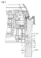
Der Dämmblock 6 weist einen Dämmschenkel 7 auf, welcher auf einer Außenseite des Blendrahmens 3 vorgesehen ist. Der Dämmschenkel 7 ist von einem Befestigungselement 8 durchgriffen, welches an dem Blendrahmen 3 befestigt ist, und der Befestigung des Dachfensters 1 an den Dachelementen dient. Der Dämmschenkel 7 ist mittels einer Formschlussverbindung 9 an dem Blendrahmen 3 befestigt. Die Formschlussverbindung 9 weist dazu einen Vorsprung 10 auf, an welchem Rastelemente 11 in Form von Eingriffsnasen 12 vorgesehen sind. Letztere sind elastisch ausgebildet, sodass sie sich nach einem Einbringen in eine Ausnehmung 13 des Dämmblocks 6 in dieser aufweiten können und von Verjüngungen 14 der Ausnehmung 13 an einem Herausrutschen und damit einem Lösen der Verbindung gehindert werden. Auf diese Weise ist also eine Klipsverbindung zwischen Blendrahmen 3 und Dämmblock 6 beziehungsweise Dämmschenkel 7 hergestellt. Das Befestigungselement 8 kann beispielsweise ebenfalls an dem Vorsprung 10 befestigt sein. Es ist aber auch eine Befestigung direkt an dem Blendrahmen 3 möglich. Der Dämmblock 6 ist durch einen Regenschutz 15 vor von dem Dachfenster 1 abtropfendem Wasser geschützt. Der Regenschutz 15 weist eine Dichtlippe 16, welche nach einer Montage des Dachfensters 1 beispielsweise auf nicht dargestellten Dachziegeln aufliegt, und einen Wasserablaufkanal 17 zur Abführung herabgetropften Wassers auf. Auf diese Weise ist der Dämmblock 6 bereits vor einem Teil der Witterungseinflüsse von der Außenseite 5 geschützt.The insulating
Der Dämmblock 6 beziehungsweise der Dämmschenkel 7 sind an eine Kontur des Blendrahmens 3 angepasst, stehen also auf der dem Dämmblock 6 zugewandten Seite zu großen Teilen mit diesem in Berührkontakt. An einem unteren Ende 18 weist der Dämmschenkel 7 eine Aussparung 19 auf, die einen Teil einer lösbaren Verbindung 20 in Form einer Formschlussverbindung 21 bildet. Das Dachfenster 1 weist eine Fensterebene auf, wobei der Dämmschenkel 7 in einer Ebene liegt, die parallel zu dieser Fensterebene verläuft. Die Fensterebene ist dabei beispielsweise durch eine Verglasung (nicht dargestellt) des Dachfensters 1 definiert.The insulating
Die
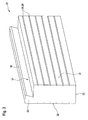
Zur Ausbildung der Formschlussverbindung 21 weist der Dämmschenkel 7 eine Haltenase 26 auf, die in Richtung des Blendrahmens 3 vorspringt. Die Haltenase 26 greift in eine Rastausnehmung 27 des Dämmschenkelvergrößerungsschenkels 22 ein. Auf diese Weise ist der Dämmschenkelvergrößerungsschenkel 22 zwischen der Auflagefläche 24 des Blendrahmens 3 und dem Dämmschenkel 7 gehalten, sodass ein unbeabsichtigtes Herausrutschen aus der Aussparung 19 nicht möglich ist. Generell ist die Formschlussverbindung 21 jedoch lösbar ausgelegt, indem das Formschlusselement 23 aus dem elastischen Material vorgesehen ist. Damit ist unter Aufwendung einer bestimmten Kraft ein Herausbewegen des Formschlusselements 23 aus der Aussparung 19 möglich. Es ist erkennbar, dass der Dämmschenkelvergrößerungsschenkel 22 über Höhenablängkennzeichnungen 28 verfügt, die ein Ablängen beziehungsweise ein Maßnehmen für das Ablängen für einen Monteur des Dachfensters 1 vereinfachen sollen. Die Höhenablängkennzeichen 28 sind als Ablängkerben 29 ausgebildet, bilden also Vertiefungen in dem Dämmschenkelvergrößerungsschenkel 22.To form the positive connection 21, the
Die
Die
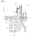
Der Dämmschenkelvergrößerungsschenkel 22 ist mit Hilfe des Formschlusselements 23, welches zwischen dem Blendrahmen 3 und dem Dämmschenkel 7 klemmend gehalten ist, befestigt. Dabei liegt er mit seiner zweiten Seitenfläche 32 auf dem Dachsparren 35 auf. Auf diese Weise liegt eine thermische Isolierung des Innenraums von der Umgebung 4 vor, da zum einen der Blendrahmen 3 nicht mit der Dachkonstruktion 34 in Berührung steht und zum anderen durch das Aufliegen des Dämmschenkelvergrößerungsschenkels 22 auf dem Dachsparren 35 eine hervorragende Dicht- beziehungsweise Isolierungswirkung vorliegt. Für die Zwischensparrendämmung ist eine Dampfbremse 37 in Form eines folienartigen Elements vorgesehen. Die Verlängerung des Dämmschenkels 7 mittels des Dämmschenkelvergrößerungsschenkels 22 hat den Vorteil, das nicht, wie aus dem Stand der Technik bekannt, die Dampfbremse 37 mit einer weiteren Folie quasi ohne Widerhalt miteinander verklebt werden muss, sondern auf den Dämmschenkelvergrößerungsschenkel 22 beziehungsweise den Dämmblock 6 geklebt werden kann. Dies vereinfacht die Montage des Dachfensters 1 beziehungsweise der Dampfbremse 37 deutlich. Nicht dargestellt sind in
Die
Claims (11)
Priority Applications (1)
| Application Number | Priority Date | Filing Date | Title |
|---|---|---|---|
| PL09012783T PL2182132T3 (en) | 2008-11-04 | 2009-10-09 | Skylight, in particular for dwelling with particular insulation arrangement |
Applications Claiming Priority (1)
| Application Number | Priority Date | Filing Date | Title |
|---|---|---|---|
| DE200810055744 DE102008055744B4 (en) | 2008-11-04 | 2008-11-04 | Roof windows, in particular roof windows |
Publications (3)
| Publication Number | Publication Date |
|---|---|
| EP2182132A2 true EP2182132A2 (en) | 2010-05-05 |
| EP2182132A3 EP2182132A3 (en) | 2012-04-11 |
| EP2182132B1 EP2182132B1 (en) | 2018-12-19 |
Family
ID=41527676
Family Applications (1)
| Application Number | Title | Priority Date | Filing Date |
|---|---|---|---|
| EP09012783.8A Active EP2182132B1 (en) | 2008-11-04 | 2009-10-09 | Skylight, in particular for dwelling with particular insulation arrangement |
Country Status (3)
| Country | Link |
|---|---|
| EP (1) | EP2182132B1 (en) |
| DE (1) | DE102008055744B4 (en) |
| PL (1) | PL2182132T3 (en) |
Cited By (6)
| Publication number | Priority date | Publication date | Assignee | Title |
|---|---|---|---|---|
| EP2466032A1 (en) * | 2010-12-17 | 2012-06-20 | VKR Holding A/S | An insulating member comprising two elements of different material and a method for insulating a window in an inclined roof structure with this insulating member |
| EP3045608A1 (en) * | 2015-01-16 | 2016-07-20 | Roto Frank Ag | Installation element for a skylight and skylight assembly with a skylight and an installation element |
| EP3128097A1 (en) * | 2015-08-04 | 2017-02-08 | VKR Holding A/S | An insulating member and a method for insulating a roof window |
| DK201570503A1 (en) * | 2015-08-04 | 2017-02-27 | Vkr Holding As | Method for packaging a window with frame insulation and a packed window |
| EP3683375A1 (en) * | 2019-01-15 | 2020-07-22 | VKR Holding A/S | Insulation frame comprising a transient deformation zone |
| WO2023186239A1 (en) * | 2022-03-31 | 2023-10-05 | Vkr Holding A/S | A roof window comprising a frame with receiving structures |
Families Citing this family (2)
| Publication number | Priority date | Publication date | Assignee | Title |
|---|---|---|---|---|
| DE102011102912B4 (en) * | 2011-05-31 | 2021-12-16 | Roto Frank Ag | Skylights, frames and casement frames and methods of manufacturing the same |
| DE102016218259A1 (en) | 2016-09-22 | 2018-03-22 | Roto Frank Ag | Insulating block for a building closure, building closure with an insulating block and method for mounting a building closure |
Citations (4)
| Publication number | Priority date | Publication date | Assignee | Title |
|---|---|---|---|---|
| EP0679773A1 (en) * | 1994-04-26 | 1995-11-02 | ROTO FRANK Aktiengesellschaft | Skylight frame |
| DE20203854U1 (en) * | 2002-03-11 | 2002-07-18 | Schlott, Wolfgang, 88690 Uhldingen-Mühlhofen | Insulation frame for roof windows |
| EP1550777A1 (en) * | 2003-12-30 | 2005-07-06 | VKR Holding A/S | Window and insulating frame kit |
| EP1739247A1 (en) * | 2005-06-30 | 2007-01-03 | VKR Holding A/S | An insulating frame for a roof window |
-
2008
- 2008-11-04 DE DE200810055744 patent/DE102008055744B4/en not_active Expired - Fee Related
-
2009
- 2009-10-09 EP EP09012783.8A patent/EP2182132B1/en active Active
- 2009-10-09 PL PL09012783T patent/PL2182132T3/en unknown
Patent Citations (4)
| Publication number | Priority date | Publication date | Assignee | Title |
|---|---|---|---|---|
| EP0679773A1 (en) * | 1994-04-26 | 1995-11-02 | ROTO FRANK Aktiengesellschaft | Skylight frame |
| DE20203854U1 (en) * | 2002-03-11 | 2002-07-18 | Schlott, Wolfgang, 88690 Uhldingen-Mühlhofen | Insulation frame for roof windows |
| EP1550777A1 (en) * | 2003-12-30 | 2005-07-06 | VKR Holding A/S | Window and insulating frame kit |
| EP1739247A1 (en) * | 2005-06-30 | 2007-01-03 | VKR Holding A/S | An insulating frame for a roof window |
Cited By (10)
| Publication number | Priority date | Publication date | Assignee | Title |
|---|---|---|---|---|
| EP2466032A1 (en) * | 2010-12-17 | 2012-06-20 | VKR Holding A/S | An insulating member comprising two elements of different material and a method for insulating a window in an inclined roof structure with this insulating member |
| CN102561608A (en) * | 2010-12-17 | 2012-07-11 | Vkr控股公司 | An insulating member and a method for insulating a window in an inclined roof structure with this insulating member |
| CN102561608B (en) * | 2010-12-17 | 2016-03-16 | Vkr控股公司 | Isolation member and the method for the window in the roof structure of isolated inclination |
| EP3181776A1 (en) * | 2010-12-17 | 2017-06-21 | VKR Holding A/S | A flashing and a tile supprort for a roof window |
| EP3045608A1 (en) * | 2015-01-16 | 2016-07-20 | Roto Frank Ag | Installation element for a skylight and skylight assembly with a skylight and an installation element |
| EP3128097A1 (en) * | 2015-08-04 | 2017-02-08 | VKR Holding A/S | An insulating member and a method for insulating a roof window |
| DK201570503A1 (en) * | 2015-08-04 | 2017-02-27 | Vkr Holding As | Method for packaging a window with frame insulation and a packed window |
| DK201570502A1 (en) * | 2015-08-04 | 2017-03-06 | Vkr Holding As | An insulating member and a method for insulating a roof window |
| EP3683375A1 (en) * | 2019-01-15 | 2020-07-22 | VKR Holding A/S | Insulation frame comprising a transient deformation zone |
| WO2023186239A1 (en) * | 2022-03-31 | 2023-10-05 | Vkr Holding A/S | A roof window comprising a frame with receiving structures |
Also Published As
| Publication number | Publication date |
|---|---|
| DE102008055744B4 (en) | 2010-07-29 |
| DE102008055744A1 (en) | 2010-05-12 |
| PL2182132T3 (en) | 2019-07-31 |
| EP2182132A3 (en) | 2012-04-11 |
| EP2182132B1 (en) | 2018-12-19 |
Similar Documents
| Publication | Publication Date | Title |
|---|---|---|
| EP2182132B1 (en) | Skylight, in particular for dwelling with particular insulation arrangement | |
| DE10044268A1 (en) | Pipe suspension bracket for building roof interior has retaining plate of rectangular shape fitting into gap in profiled roof panel | |
| DE102007053373A1 (en) | Mounting bracket for solar collector, has U-shaped section for force-fit mounting on corresponding rail and another section for force-fit fixing of collector | |
| EP2253769B1 (en) | Assembly of structural elements for a roof | |
| DE102005053639B4 (en) | Mounting system for solar modules | |
| DE102010022845B4 (en) | Edge protection element for the arrangement of unframed PV modules | |
| EP2947227B1 (en) | Residential skylight with sheet metal frame cover | |
| EP0215231A2 (en) | Vaulted roof skylight arranged on a mounting cornice or the like | |
| EP2679929A1 (en) | Assembly and seal system for installing a number of board-shaped modules in an inclined roof | |
| EP0450289B1 (en) | Composite wooden and metal frame for windows, doors and the like | |
| DE10216625B4 (en) | Fastening device for a sealing support of a sheet | |
| AT513415B1 (en) | Windowsill final | |
| DE102016007242B4 (en) | Device for covering the outer area of the lower boundary of a building opening | |
| EP2947229B1 (en) | Roof window and method for mounting a roof window | |
| EP2439464A2 (en) | Insertion profile for fitting holder profiles for board-shaped modules and multi-section frame comprising same | |
| EP2505936A1 (en) | Mounting device for a mounting profile | |
| DE102020209060A1 (en) | Installation frame for installing a roof window, roof window assembly, roof assembly and method for installing a roof window | |
| DE20203854U1 (en) | Insulation frame for roof windows | |
| DE29501224U1 (en) | Substructure for pitched roofs covered with roof tiles | |
| EP3045611B1 (en) | Pane holder and fastening system for façade panels | |
| EP3625424A1 (en) | Cover assembly for windows | |
| DE102011057028A1 (en) | Support for mounting solar module on roof of building, has mounting block with opening opened downward to base plate and closed upward for receiving screw guided from below, where seal is arranged between mounting block and base plate | |
| DE102010021426B4 (en) | solar collector | |
| EP2372038B1 (en) | Façade construction | |
| DE102005060477A1 (en) | Concealed roof outlet for building ventilation, discharges into ventilation cavity covered by ridge tiles through angled ductwork fitting with circular and flattened ends |
Legal Events
| Date | Code | Title | Description |
|---|---|---|---|
| PUAI | Public reference made under article 153(3) epc to a published international application that has entered the european phase |
Free format text: ORIGINAL CODE: 0009012 |
|
| AK | Designated contracting states |
Kind code of ref document: A2 Designated state(s): AT BE BG CH CY CZ DE DK EE ES FI FR GB GR HR HU IE IS IT LI LT LU LV MC MK MT NL NO PL PT RO SE SI SK SM TR |
|
| AX | Request for extension of the european patent |
Extension state: AL BA RS |
|
| PUAL | Search report despatched |
Free format text: ORIGINAL CODE: 0009013 |
|
| AK | Designated contracting states |
Kind code of ref document: A3 Designated state(s): AT BE BG CH CY CZ DE DK EE ES FI FR GB GR HR HU IE IS IT LI LT LU LV MC MK MT NL NO PL PT RO SE SI SK SM TR |
|
| AX | Request for extension of the european patent |
Extension state: AL BA RS |
|
| RIC1 | Information provided on ipc code assigned before grant |
Ipc: E04D 13/03 20060101AFI20120306BHEP |
|
| 17P | Request for examination filed |
Effective date: 20121011 |
|
| STAA | Information on the status of an ep patent application or granted ep patent |
Free format text: STATUS: EXAMINATION IS IN PROGRESS |
|
| 17Q | First examination report despatched |
Effective date: 20171121 |
|
| GRAP | Despatch of communication of intention to grant a patent |
Free format text: ORIGINAL CODE: EPIDOSNIGR1 |
|
| STAA | Information on the status of an ep patent application or granted ep patent |
Free format text: STATUS: GRANT OF PATENT IS INTENDED |
|
| INTG | Intention to grant announced |
Effective date: 20180308 |
|
| GRAJ | Information related to disapproval of communication of intention to grant by the applicant or resumption of examination proceedings by the epo deleted |
Free format text: ORIGINAL CODE: EPIDOSDIGR1 |
|
| STAA | Information on the status of an ep patent application or granted ep patent |
Free format text: STATUS: EXAMINATION IS IN PROGRESS |
|
| INTC | Intention to grant announced (deleted) | ||
| RAP1 | Party data changed (applicant data changed or rights of an application transferred) |
Owner name: ROTO FRANK AG |
|
| GRAR | Information related to intention to grant a patent recorded |
Free format text: ORIGINAL CODE: EPIDOSNIGR71 |
|
| GRAS | Grant fee paid |
Free format text: ORIGINAL CODE: EPIDOSNIGR3 |
|
| STAA | Information on the status of an ep patent application or granted ep patent |
Free format text: STATUS: GRANT OF PATENT IS INTENDED |
|
| GRAA | (expected) grant |
Free format text: ORIGINAL CODE: 0009210 |
|
| STAA | Information on the status of an ep patent application or granted ep patent |
Free format text: STATUS: THE PATENT HAS BEEN GRANTED |
|
| INTG | Intention to grant announced |
Effective date: 20181108 |
|
| AK | Designated contracting states |
Kind code of ref document: B1 Designated state(s): AT BE BG CH CY CZ DE DK EE ES FI FR GB GR HR HU IE IS IT LI LT LU LV MC MK MT NL NO PL PT RO SE SI SK SM TR |
|
| REG | Reference to a national code |
Ref country code: GB Ref legal event code: FG4D Free format text: NOT ENGLISH |
|
| REG | Reference to a national code |
Ref country code: CH Ref legal event code: EP |
|
| REG | Reference to a national code |
Ref country code: IE Ref legal event code: FG4D Free format text: LANGUAGE OF EP DOCUMENT: GERMAN |
|
| REG | Reference to a national code |
Ref country code: DE Ref legal event code: R096 Ref document number: 502009015516 Country of ref document: DE |
|
| REG | Reference to a national code |
Ref country code: AT Ref legal event code: REF Ref document number: 1078874 Country of ref document: AT Kind code of ref document: T Effective date: 20190115 |
|
| REG | Reference to a national code |
Ref country code: CH Ref legal event code: NV Representative=s name: OFFICE ERNEST T. FREYLINGER S.A., CH |
|
| REG | Reference to a national code |
Ref country code: NL Ref legal event code: MP Effective date: 20181219 |
|
| PG25 | Lapsed in a contracting state [announced via postgrant information from national office to epo] |
Ref country code: LV Free format text: LAPSE BECAUSE OF FAILURE TO SUBMIT A TRANSLATION OF THE DESCRIPTION OR TO PAY THE FEE WITHIN THE PRESCRIBED TIME-LIMIT Effective date: 20181219 Ref country code: FI Free format text: LAPSE BECAUSE OF FAILURE TO SUBMIT A TRANSLATION OF THE DESCRIPTION OR TO PAY THE FEE WITHIN THE PRESCRIBED TIME-LIMIT Effective date: 20181219 Ref country code: BG Free format text: LAPSE BECAUSE OF FAILURE TO SUBMIT A TRANSLATION OF THE DESCRIPTION OR TO PAY THE FEE WITHIN THE PRESCRIBED TIME-LIMIT Effective date: 20190319 Ref country code: HR Free format text: LAPSE BECAUSE OF FAILURE TO SUBMIT A TRANSLATION OF THE DESCRIPTION OR TO PAY THE FEE WITHIN THE PRESCRIBED TIME-LIMIT Effective date: 20181219 Ref country code: NO Free format text: LAPSE BECAUSE OF FAILURE TO SUBMIT A TRANSLATION OF THE DESCRIPTION OR TO PAY THE FEE WITHIN THE PRESCRIBED TIME-LIMIT Effective date: 20190319 Ref country code: LT Free format text: LAPSE BECAUSE OF FAILURE TO SUBMIT A TRANSLATION OF THE DESCRIPTION OR TO PAY THE FEE WITHIN THE PRESCRIBED TIME-LIMIT Effective date: 20181219 |
|
| REG | Reference to a national code |
Ref country code: LT Ref legal event code: MG4D |
|
| PG25 | Lapsed in a contracting state [announced via postgrant information from national office to epo] |
Ref country code: GR Free format text: LAPSE BECAUSE OF FAILURE TO SUBMIT A TRANSLATION OF THE DESCRIPTION OR TO PAY THE FEE WITHIN THE PRESCRIBED TIME-LIMIT Effective date: 20190320 Ref country code: SE Free format text: LAPSE BECAUSE OF FAILURE TO SUBMIT A TRANSLATION OF THE DESCRIPTION OR TO PAY THE FEE WITHIN THE PRESCRIBED TIME-LIMIT Effective date: 20181219 |
|
| PG25 | Lapsed in a contracting state [announced via postgrant information from national office to epo] |
Ref country code: NL Free format text: LAPSE BECAUSE OF FAILURE TO SUBMIT A TRANSLATION OF THE DESCRIPTION OR TO PAY THE FEE WITHIN THE PRESCRIBED TIME-LIMIT Effective date: 20181219 |
|
| PG25 | Lapsed in a contracting state [announced via postgrant information from national office to epo] |
Ref country code: ES Free format text: LAPSE BECAUSE OF FAILURE TO SUBMIT A TRANSLATION OF THE DESCRIPTION OR TO PAY THE FEE WITHIN THE PRESCRIBED TIME-LIMIT Effective date: 20181219 Ref country code: PT Free format text: LAPSE BECAUSE OF FAILURE TO SUBMIT A TRANSLATION OF THE DESCRIPTION OR TO PAY THE FEE WITHIN THE PRESCRIBED TIME-LIMIT Effective date: 20190419 Ref country code: IT Free format text: LAPSE BECAUSE OF FAILURE TO SUBMIT A TRANSLATION OF THE DESCRIPTION OR TO PAY THE FEE WITHIN THE PRESCRIBED TIME-LIMIT Effective date: 20181219 |
|
| PG25 | Lapsed in a contracting state [announced via postgrant information from national office to epo] |
Ref country code: IS Free format text: LAPSE BECAUSE OF FAILURE TO SUBMIT A TRANSLATION OF THE DESCRIPTION OR TO PAY THE FEE WITHIN THE PRESCRIBED TIME-LIMIT Effective date: 20190419 Ref country code: RO Free format text: LAPSE BECAUSE OF FAILURE TO SUBMIT A TRANSLATION OF THE DESCRIPTION OR TO PAY THE FEE WITHIN THE PRESCRIBED TIME-LIMIT Effective date: 20181219 Ref country code: SK Free format text: LAPSE BECAUSE OF FAILURE TO SUBMIT A TRANSLATION OF THE DESCRIPTION OR TO PAY THE FEE WITHIN THE PRESCRIBED TIME-LIMIT Effective date: 20181219 Ref country code: EE Free format text: LAPSE BECAUSE OF FAILURE TO SUBMIT A TRANSLATION OF THE DESCRIPTION OR TO PAY THE FEE WITHIN THE PRESCRIBED TIME-LIMIT Effective date: 20181219 Ref country code: SM Free format text: LAPSE BECAUSE OF FAILURE TO SUBMIT A TRANSLATION OF THE DESCRIPTION OR TO PAY THE FEE WITHIN THE PRESCRIBED TIME-LIMIT Effective date: 20181219 |
|
| REG | Reference to a national code |
Ref country code: DE Ref legal event code: R097 Ref document number: 502009015516 Country of ref document: DE |
|
| PLBE | No opposition filed within time limit |
Free format text: ORIGINAL CODE: 0009261 |
|
| STAA | Information on the status of an ep patent application or granted ep patent |
Free format text: STATUS: NO OPPOSITION FILED WITHIN TIME LIMIT |
|
| PG25 | Lapsed in a contracting state [announced via postgrant information from national office to epo] |
Ref country code: DK Free format text: LAPSE BECAUSE OF FAILURE TO SUBMIT A TRANSLATION OF THE DESCRIPTION OR TO PAY THE FEE WITHIN THE PRESCRIBED TIME-LIMIT Effective date: 20181219 |
|
| 26N | No opposition filed |
Effective date: 20190920 |
|
| PG25 | Lapsed in a contracting state [announced via postgrant information from national office to epo] |
Ref country code: SI Free format text: LAPSE BECAUSE OF FAILURE TO SUBMIT A TRANSLATION OF THE DESCRIPTION OR TO PAY THE FEE WITHIN THE PRESCRIBED TIME-LIMIT Effective date: 20181219 |
|
| PG25 | Lapsed in a contracting state [announced via postgrant information from national office to epo] |
Ref country code: TR Free format text: LAPSE BECAUSE OF FAILURE TO SUBMIT A TRANSLATION OF THE DESCRIPTION OR TO PAY THE FEE WITHIN THE PRESCRIBED TIME-LIMIT Effective date: 20181219 |
|
| PG25 | Lapsed in a contracting state [announced via postgrant information from national office to epo] |
Ref country code: MC Free format text: LAPSE BECAUSE OF FAILURE TO SUBMIT A TRANSLATION OF THE DESCRIPTION OR TO PAY THE FEE WITHIN THE PRESCRIBED TIME-LIMIT Effective date: 20181219 |
|
| PG25 | Lapsed in a contracting state [announced via postgrant information from national office to epo] |
Ref country code: LU Free format text: LAPSE BECAUSE OF NON-PAYMENT OF DUE FEES Effective date: 20191009 |
|
| REG | Reference to a national code |
Ref country code: BE Ref legal event code: MM Effective date: 20191031 |
|
| PG25 | Lapsed in a contracting state [announced via postgrant information from national office to epo] |
Ref country code: BE Free format text: LAPSE BECAUSE OF NON-PAYMENT OF DUE FEES Effective date: 20191031 |
|
| PG25 | Lapsed in a contracting state [announced via postgrant information from national office to epo] |
Ref country code: IE Free format text: LAPSE BECAUSE OF NON-PAYMENT OF DUE FEES Effective date: 20191009 |
|
| PG25 | Lapsed in a contracting state [announced via postgrant information from national office to epo] |
Ref country code: CY Free format text: LAPSE BECAUSE OF FAILURE TO SUBMIT A TRANSLATION OF THE DESCRIPTION OR TO PAY THE FEE WITHIN THE PRESCRIBED TIME-LIMIT Effective date: 20181219 |
|
| PG25 | Lapsed in a contracting state [announced via postgrant information from national office to epo] |
Ref country code: HU Free format text: LAPSE BECAUSE OF FAILURE TO SUBMIT A TRANSLATION OF THE DESCRIPTION OR TO PAY THE FEE WITHIN THE PRESCRIBED TIME-LIMIT; INVALID AB INITIO Effective date: 20091009 Ref country code: MT Free format text: LAPSE BECAUSE OF FAILURE TO SUBMIT A TRANSLATION OF THE DESCRIPTION OR TO PAY THE FEE WITHIN THE PRESCRIBED TIME-LIMIT Effective date: 20181219 |
|
| PG25 | Lapsed in a contracting state [announced via postgrant information from national office to epo] |
Ref country code: MK Free format text: LAPSE BECAUSE OF FAILURE TO SUBMIT A TRANSLATION OF THE DESCRIPTION OR TO PAY THE FEE WITHIN THE PRESCRIBED TIME-LIMIT Effective date: 20181219 |
|
| PGFP | Annual fee paid to national office [announced via postgrant information from national office to epo] |
Ref country code: CZ Payment date: 20230926 Year of fee payment: 15 |
|
| PGFP | Annual fee paid to national office [announced via postgrant information from national office to epo] |
Ref country code: PL Payment date: 20230928 Year of fee payment: 15 |
|
| PGFP | Annual fee paid to national office [announced via postgrant information from national office to epo] |
Ref country code: GB Payment date: 20231025 Year of fee payment: 15 |
|
| PGFP | Annual fee paid to national office [announced via postgrant information from national office to epo] |
Ref country code: FR Payment date: 20231023 Year of fee payment: 15 Ref country code: DE Payment date: 20231018 Year of fee payment: 15 Ref country code: CH Payment date: 20231102 Year of fee payment: 15 Ref country code: AT Payment date: 20231019 Year of fee payment: 15 |