EP2181919A2 - Hydraulische Steuerung für ein Schiffsgetriebe - Google Patents
Hydraulische Steuerung für ein Schiffsgetriebe Download PDFInfo
- Publication number
- EP2181919A2 EP2181919A2 EP09171592A EP09171592A EP2181919A2 EP 2181919 A2 EP2181919 A2 EP 2181919A2 EP 09171592 A EP09171592 A EP 09171592A EP 09171592 A EP09171592 A EP 09171592A EP 2181919 A2 EP2181919 A2 EP 2181919A2
- Authority
- EP
- European Patent Office
- Prior art keywords
- valve
- system pressure
- lubricant
- pump
- control
- Prior art date
- Legal status (The legal status is an assumption and is not a legal conclusion. Google has not performed a legal analysis and makes no representation as to the accuracy of the status listed.)
- Granted
Links
Images

Classifications
-
- F—MECHANICAL ENGINEERING; LIGHTING; HEATING; WEAPONS; BLASTING
- F16—ENGINEERING ELEMENTS AND UNITS; GENERAL MEASURES FOR PRODUCING AND MAINTAINING EFFECTIVE FUNCTIONING OF MACHINES OR INSTALLATIONS; THERMAL INSULATION IN GENERAL
- F16D—COUPLINGS FOR TRANSMITTING ROTATION; CLUTCHES; BRAKES
- F16D48/00—External control of clutches
- F16D48/02—Control by fluid pressure
-
- B—PERFORMING OPERATIONS; TRANSPORTING
- B63—SHIPS OR OTHER WATERBORNE VESSELS; RELATED EQUIPMENT
- B63H—MARINE PROPULSION OR STEERING
- B63H21/00—Use of propulsion power plant or units on vessels
- B63H21/38—Apparatus or methods specially adapted for use on marine vessels, for handling power plant or unit liquids, e.g. lubricants, coolants, fuels or the like
-
- B—PERFORMING OPERATIONS; TRANSPORTING
- B63—SHIPS OR OTHER WATERBORNE VESSELS; RELATED EQUIPMENT
- B63H—MARINE PROPULSION OR STEERING
- B63H21/00—Use of propulsion power plant or units on vessels
- B63H21/38—Apparatus or methods specially adapted for use on marine vessels, for handling power plant or unit liquids, e.g. lubricants, coolants, fuels or the like
- B63H21/386—Apparatus or methods specially adapted for use on marine vessels, for handling power plant or unit liquids, e.g. lubricants, coolants, fuels or the like for handling lubrication liquids
-
- B—PERFORMING OPERATIONS; TRANSPORTING
- B63—SHIPS OR OTHER WATERBORNE VESSELS; RELATED EQUIPMENT
- B63J—AUXILIARIES ON VESSELS
- B63J3/00—Driving of auxiliaries
- B63J3/02—Driving of auxiliaries from propulsion power plant
-
- F—MECHANICAL ENGINEERING; LIGHTING; HEATING; WEAPONS; BLASTING
- F16—ENGINEERING ELEMENTS AND UNITS; GENERAL MEASURES FOR PRODUCING AND MAINTAINING EFFECTIVE FUNCTIONING OF MACHINES OR INSTALLATIONS; THERMAL INSULATION IN GENERAL
- F16H—GEARING
- F16H57/00—General details of gearing
- F16H57/04—Features relating to lubrication or cooling or heating
- F16H57/0434—Features relating to lubrication or cooling or heating relating to lubrication supply, e.g. pumps; Pressure control
- F16H57/0435—Pressure control for supplying lubricant; Circuits or valves therefor
-
- F—MECHANICAL ENGINEERING; LIGHTING; HEATING; WEAPONS; BLASTING
- F16—ENGINEERING ELEMENTS AND UNITS; GENERAL MEASURES FOR PRODUCING AND MAINTAINING EFFECTIVE FUNCTIONING OF MACHINES OR INSTALLATIONS; THERMAL INSULATION IN GENERAL
- F16H—GEARING
- F16H57/00—General details of gearing
- F16H57/04—Features relating to lubrication or cooling or heating
- F16H57/0434—Features relating to lubrication or cooling or heating relating to lubrication supply, e.g. pumps; Pressure control
- F16H57/0436—Pumps
- F16H57/0439—Pumps using multiple pumps with different power sources or a single pump with different power sources, e.g. one and the same pump may selectively be driven by either the engine or an electric motor
-
- F—MECHANICAL ENGINEERING; LIGHTING; HEATING; WEAPONS; BLASTING
- F01—MACHINES OR ENGINES IN GENERAL; ENGINE PLANTS IN GENERAL; STEAM ENGINES
- F01M—LUBRICATING OF MACHINES OR ENGINES IN GENERAL; LUBRICATING INTERNAL COMBUSTION ENGINES; CRANKCASE VENTILATING
- F01M1/00—Pressure lubrication
- F01M1/16—Controlling lubricant pressure or quantity
-
- F—MECHANICAL ENGINEERING; LIGHTING; HEATING; WEAPONS; BLASTING
- F16—ENGINEERING ELEMENTS AND UNITS; GENERAL MEASURES FOR PRODUCING AND MAINTAINING EFFECTIVE FUNCTIONING OF MACHINES OR INSTALLATIONS; THERMAL INSULATION IN GENERAL
- F16D—COUPLINGS FOR TRANSMITTING ROTATION; CLUTCHES; BRAKES
- F16D48/00—External control of clutches
- F16D48/02—Control by fluid pressure
- F16D2048/0257—Hydraulic circuit layouts, i.e. details of hydraulic circuit elements or the arrangement thereof
- F16D2048/0287—Hydraulic circuits combining clutch actuation and other hydraulic systems
- F16D2048/029—Hydraulic circuits combining clutch actuation with clutch lubrication or cooling
-
- F—MECHANICAL ENGINEERING; LIGHTING; HEATING; WEAPONS; BLASTING
- F16—ENGINEERING ELEMENTS AND UNITS; GENERAL MEASURES FOR PRODUCING AND MAINTAINING EFFECTIVE FUNCTIONING OF MACHINES OR INSTALLATIONS; THERMAL INSULATION IN GENERAL
- F16D—COUPLINGS FOR TRANSMITTING ROTATION; CLUTCHES; BRAKES
- F16D48/00—External control of clutches
- F16D48/02—Control by fluid pressure
- F16D2048/0257—Hydraulic circuit layouts, i.e. details of hydraulic circuit elements or the arrangement thereof
- F16D2048/0287—Hydraulic circuits combining clutch actuation and other hydraulic systems
- F16D2048/0293—Hydraulic circuits combining clutch and transmission actuation
Definitions
- the present invention relates to a hydraulic control for a marine gear according to the closer defined in the preamble of claim 1. Art.
- Hydraulic controls for marine gear usually include, inter alia, a system pressure valve with a desired system pressure is adjusted to control, for example, the clutch of the marine gearbox.
- the system pressure valve also supplies the lubricant circuit with lubricant, for example oil.
- the system pressure valve with its outlet is connected to the lubricant circuit.
- a primary pump is driven via the drive shaft, which promotes a sufficient amount of oil with a predetermined system pressure.
- the system pressure valve opens, allowing the oil or lubricant to flow into the lubricant circuit.
- the towing pump is combined with a pressure relief valve for its own protection, which opens at a pressure below the system pressure. When this pressure is reached, the lubricant is directed into a transmission oil sump. Thus, the towing pump can not apply the system pressure, which opens the system pressure valve for lubricant supply.
- the present invention is therefore based on the object to propose a hydraulic control according to the type described above, which is modified such that a lubricant supply is ensured even with a motor stall and rotating output shaft to the components of the marine gear in this state with lubricant to supply.
- a hydraulic control system for a marine transmission with at least one system pressure valve for adjusting a predetermined system pressure and lubricant supply while driving wherein the system pressure valve is connected to a driven by a drive shaft primary pump and wherein a driven by an output shaft drag running pump for lubricant supply at least in towing operation in parallel connected or arranged to the primary pump.
- at least one lubricant-quantity-controlled or oil-quantity-controlled control valve or the like is provided for supplying lubricant in the case of a rotating output shaft.
- the control valve may also be referred to as a towing valve.
- the invention may be provided that the control valve depends on the pressure or pressure Flow rate is controlled. Accordingly, the control valve is opened below a predetermined minimum delivery of the primary pump for supplying lubricant and closed when reaching or exceeding the minimum delivery.
- the control valve is spring-loaded and designed with a diaphragm at the outlet or the like.
- the corresponding closing pressure is achieved when increasing the flow rate at which the control valve is closed when the primary pump delivers the appropriate amount of oil.
- the spring can be adjusted so that upon reaching a pressure corresponding to an amount of oil that is greater than a minimum delivery rate of the primary pump, for example, at an idling speed of the engine, the piston of the control valve is moved to its closed position. Thus, no more oil flows through the drag travel valve or control valve in the lubricant circuit.
- control valve is bypassed by the system pressure valve and the control of the lubricating oil is again via the system pressure valve.
- the towing valve or control valve can easily on different pressures and flow rates be set.
- the closing pressure on the compression spring and the ⁇ lsch spamenge can be adjusted via the aperture.
- control valve can be universally adapted to different transmission types with different pumps and flow rates.
- the outlet which is connected to the lubricant supply or the lubricant circuit, closed by a spring until a predetermined system pressure is reached. Since the inlet of the control valve is connected to the inlet of the system pressure valve, the lubricant can be conveyed via the inlet of the system pressure valve in the control valve at a pressure below the system pressure. Since the outlet of the system pressure valve connected to the lubricant supply is also connected to the outlet of the control valve, a supply of lubricant via the control valve below the system pressure can thus be realized.
- the towing pump is connected via a lubricant preparation device with the system pressure valve and the downstream control valve or drag travel valve. This prevents the towing pump from being directly connected to the lubricant circuit.
- This has the advantage that the oil or lubricant is conveyed through the lubricant preparation device. In this way, for example, cooled and filtered lubricant is conveyed into the lubricant circuit, so that damage to the transmission is prevented.
- the oil can also become very warm in the drag valve. If the oil then does not flow over the cooler of the treatment device, its cooling effect can not be used. Without the towing valve according to the invention would therefore be an additional filter and In some cases, an additional cooler required, which leads to higher costs, a higher installation costs and maintenance and an increase in the sealing points on the gearbox. These additional measures can be saved in the inventively proposed control.
- the controller is designed as a compact control block on which the control valve or drag travel valve is simply placed as an additional module.
- the control valve or drag travel valve is simply placed as an additional module.
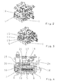
- FIG. 1 is a possible embodiment of a hydraulic control according to the invention for a marine gear illustrated by way of example in the form of a circuit diagram.
- the control is preferably, as in the FIGS. 2 to 4 can be seen, formed as a compact control block 1.
- FIG. 1 It can be seen that the control comprises a primary pump 2, which is connected via a cooler 3 and a filter 4 as a treatment device with a system pressure valve 5.
- the primary pump 2 delivers lubricant or oil from a transmission oil sump 6 to the system pressure valve.
- the primary pump 2 is driven by a drive shaft, which is not further shown.
- a piston 7 of the system pressure valve 5 is acted upon by an inlet 9 against the force of a compression spring 8 with oil, so that upon reaching a predetermined system pressure, for example 17,19 or 21.5 bar, the system pressure valve 5 is opened.
- the piston 7 of the system pressure valve 5 In the open state of the system pressure valve 5, so when concerns the system pressure, the piston 7 of the system pressure valve 5, the outlet 10 of the system pressure valve 5 is released, so that oil can enter the lubricant circuit, which is indicated by the arrow 11.
- the inlet 9 of the system pressure valve 5 is also connected, for example, to a clutch of the transmission in order to pressurize it with the system pressure for driving. This is indicated by the arrow 12.
- the lubricating oil supply for the system pressure valve 5 is made in normal driving.
- the supply of lubricant via a towing drive pump 13 is realized.
- the towing pump 13 is connected in parallel to the primary pump 2 and includes for protection, a pressure relief valve 14, which at a pressure of z. B. 12 bar opens, so that the oil is passed into the transmission oil sump 6.
- the towing pump 13 is connected via a check valve 15 and the oil cooler 3 and the filter 4 to the inlet 9 of the system pressure valve 5.
- the Towing pump 13 is driven via the output shaft of the transmission when, for example, the ship is towed or the propeller is rotated by a flow in the water.
- the system pressure valve via z. B. three connecting lines 16, 17,18 connected to an additional lubricant quantity controlled control valve or drag running valve 19.
- the connecting line 16 With the connecting line 16, the inlet 9 of the system pressure valve 5 is connected to the inlet 20 of the towing valve 19. Via the connecting line 17, the outlet 10 of the system pressure valve 5 is connected to the outlet 21 of the towing drive valve 19.
- the connecting line 18 serves as a vent.
- the system pressure for opening the system pressure valve 5 is not reached, since the primary pump is not driven, a sufficient flow rate of the lubricant is conveyed to the lubricant circuit via the drag drive pump 13, wherein the delivery rate is below the minimum delivery rate of the primary pump 2.
- the minimum delivery rate may correspond, for example, the flow rate at idle speed of the drive motor.
- the piston 7 of the system pressure valve 5 is not moved.
- the oil delivered by the trailing-way pump 13 can flow via the connecting line 16 through the inlet 20 into the trailing-way valve 19.
- the oil can be supplied via the connecting line 17 and the outlet 10 of the system pressure valve 5 to the lubricant circuit 11.
- a diaphragm 22 is arranged, which generates a pressure increase in the trailing-way valve 19.
- the resulting pressure acts on the piston 23 of the Schleppfahrtventlis against the spring force of Compression spring 24. This means that when the delivery rate reaches the minimum delivery of the primary pump 2, for example, when the primary pump is driven again, the resulting pressure causes the displacement of the piston 23, so that at least the inlet 20 of the towing valve 19 is closed.
- FIGS. 2 and 3 show perspective view of the control block 1 of the hydraulic control, wherein in FIG. 2 already the towing valve 19 is placed on the control block 1 in the area of Systemtikventlis 5.
- FIG. 3 the control block 1 is shown with the system pressure valve 5 without the trailing-way valve 19.
- FIG. 4 shows a further sectional view of the system pressure valve 5 and the trailing valve 19 in the control block 1.
- This view is the in FIG. 1 only schematically indicated sectional view of the system pressure valve 5 and the drag travel valve 19 supplement, wherein the same components with the same reference numerals as in FIG. 1 are designated.
Landscapes
- Engineering & Computer Science (AREA)
- Mechanical Engineering (AREA)
- General Engineering & Computer Science (AREA)
- Chemical & Material Sciences (AREA)
- Combustion & Propulsion (AREA)
- Ocean & Marine Engineering (AREA)
- Physics & Mathematics (AREA)
- Fluid Mechanics (AREA)
- General Details Of Gearings (AREA)
- Control Of Transmission Device (AREA)
Abstract
Description
- Die vorliegende Erfindung betrifft eine hydraulische Steuerung für ein Schiffsgetriebe gemäß der im Oberbegriff des Patentanspruches 1 näher definierten Art.
- Hydraulische Steuerungen für Schiffsgetriebe umfassen üblicherweise unter anderem ein Systemdruckventil mit dem ein gewünschter Systemdruck eingestellt wird, um zum Beispiel die Kupplung des Schiffsgetriebes anzusteuern. Neben der Ansteuerung wird durch das Systemdruckventil auch der Schmiermittelkreislauf mit Schmiermittel, zum Beispiel Öl, versorgt. Dazu ist das Systemdruckventli mit seinem Auslass an den Schmiermittelkreislauf angeschlossen.
- Für die Ölversorgung wird über die Antriebswelle eine Primärpumpe angetrieben, welche eine ausreichende Ölmenge mit einem vorbestimmten Systemdruck fördert. Wenn die Pumpe den entsprechenden Systemdruck und die entsprechende Fördermenge liefert, wird das Systemdruckventil geöffnet, so dass das Öl beziehungsweise Schmiermittel in den Schmiermittelkreislauf geleitet werden kann.
- Jedoch wird über die Primärpumpe kein Öl gefördert, wenn sich die Antriebswelle nicht mehr dreht, z. B. wenn der Motor ausgeschaltet ist, da die Primärpumpe dann ebenfalls nicht angetrieben wird. Es ist jedoch möglich, dass trotz stehender Antriebswelle die Abtriebswelle in Drehung versetzt wird und somit auch die Komponenten des Getriebes bei stehender Antriebswelle geschmiert werden müssen. Das Drehen der Abtriebswelle kann zum Beispiel beim Abschleppen des Schiffes oder auch durch eine Strömung in einem Gewässer bewirkt werden, wodurch der Propeller des Schiffes in Rotation versetzt wird. In diesem Zustand kann die Primärpumpe kein Öl in den Schmiermittelkreislauf fördern. Für diesen Betriebszustand ist es bekannt, dass eine Schleppfahrtpumpe verwendet wird, die von der Abtriebswelle angetrieben wird und dann anstelle der Primärpumpe das erforderliche Schmiermittel liefert. Die Schleppfahrtpumpe ist jedoch zum eignen Schutz mit einem Überdruckventil kombiniert, welches bei einem Druck öffnet, der unterhalb des Systemdruckes liegt. Wird dieser Druck erreicht, wird das Schmiermittel in einen Getriebeölsumpf geleitet. Somit kann die Schleppfahrtpumpe nicht den Systemdruck aufbringen, der das Systemdruckventil zur Schmiermittelversorgung öffnet.
- Der vorliegenden Erfindung liegt somit die Aufgabe zu Grunde eine hydraulische Steuerung gemäß der eingangs beschriebenen Gattung vorzuschlagen, welche derart modifiziert wird, dass eine Schmiermittelversorgung auch bei einem Motorstillstand und bei sich drehender Abtriebswelle sichergestellt wird, um die Komponenten des Schiffsgetriebes auch in diesem Zustand mit Schmiermittel zu versorgen.
- Diese Aufgabe wird erfindungsgemäß durch die Merkmale des Patentanspruches 1 gelöst. Weitere vorteilhafte Ausgestaltungen ergeben sich aus den Unteransprüchen und den Zeichnungen.
- Demnach wird eine hydraulische Steuerung für ein Schiffsgetriebe mit zumindest einem Systemdruckventil zum Einstellen eines vorbestimmten Systemdruckes und zur Schmiermittelversorgung im Fahrbetrieb vorgeschlagen, wobei das Systemdruckventil mit einer von einer Antriebswelle angetriebenen Primärpumpe verbunden ist und wobei eine von einer Abtriebswelle angetriebene Schleppfahrtpumpe zur Schmiermittelversorgung zumindest im Schleppfahrbetrieb parallel zu der Primärpumpe geschaltet bzw. angeordnet ist. Erfindungsgemäß ist zumindest ein schmiermittelmengengesteuertes bzw. ölmengengesteuertes Steuerventil oder dergleichen zur Schmiermittelversorgung bei sich drehender Abtriebswelle vorgesehen. Das Steuerventil kann auch als Schleppfahrtventil bezeichnet werden.
- Durch das Verwenden eines zusätzlichen Steuerventils bei der gattungsgemäßen Steuerung für das Schiffsgetriebe kann die Schmiermittelversorgung beziehungsweise Ölversorgung des Getriebes z. B. auch bei nicht ausreichend oder nicht angetriebener Primärpumpe sichergestellt werden.
- Um ein Schließen des Steuerventils im normalen Fahrbetrieb und ein Öffnen des Steuerventils bei stehender beziehungsweise nicht ausreichend angetriebener Antriebswelle, also bei nicht beziehungsweise nicht ausreichend angetriebener Primärpumpe, sicherzustellen, kann gemäß einer Weiterbildung der Erfindung vorgesehen sein, dass das Steuerventil in Abhängigkeit des Druckes beziehungsweise der Fördermenge angesteuert wird. Demnach wird das Steuerventil unterhalb einer vorbestimmten Mindestfördermenge der Primärpumpe zur Schmiermittelversorgung geöffnet und bei Erreichen oder Übersteigen der Mindestfördermenge wieder geschlossen.
- Gemäß einer nächsten Ausgestaltung der Erfindung kann zum Realisieren des gewünschten Schließ- beziehungsweise Öffnungsverhalten bei dem Steuerventil vorgesehen sein, dass das Steuerventil federbelastet und mit einer Blende am Auslass oder dergleichen ausgeführt ist. Durch die Blende wird bei Erhöhung des Förderstromes der entsprechende Schließdruck erreicht, bei dem das Steuerventil geschlossen wird, wenn die Primärpumpe die entsprechende Ölmenge fördert. Die Feder kann so eingestellt werden, dass bei Erreichen eines Druckes, der einer Ölmenge entspricht, die größer ist als eine Mindestfördermenge der Primärpumpe zum Beispiel bei einer Leerlaufdrehzahl des Motors, der Kolben des Steuerventils in seine Schließstellung bewegt wird. Somit fließt kein Öl mehr über das Schleppfahrtventil beziehungsweise Steuerventil in den Schmiermittelkreislauf. Demzufolge wird das Steuerventil von dem Systemdruckventil überbrückt und die Steuerung des Schmieröls erfolgt wieder über das Systemdruckventil. Das Schleppfahrtventil beziehungsweise Steuerventil kann auf einfachste Weise auf verschiedene Drücke und Fördermengen eingestellt werden. Somit kann der Schließdruck über die Druckfeder und die Ölschließmenge über die Blende eingestellt werden. In vorteilhafter Weise kann dadurch das Steuerventil universell auf verschiedene Getriebetypen mit unterschiedlichen Pumpen und Fördermengen angepasst werden.
- Bei dem Systemdruckventil wird der Auslass, der an die Schmiermittelversorgung bzw. den Schmiermittelkreislauf angeschlossen ist, über eine Feder solange verschlossen, bis ein vorbestimmter Systemdruck erreicht wird. Da der Einlass des Steuerventils mit dem Einlass des Systemdruckventils verbunden ist, kann bei einem Druck unterhalb des Systemdruckes das Schmiermittel über den Einlass des Systemdruckventils in das Steuerventil gefördert werden. Da der mit der Schmiermittelversorgung verbundene Auslass des Systemdruckventils auch mit dem Auslass des Steuerventils verbunden ist, kann somit eine Schmiermittelversorgung über das Steuerventil unterhalb des Systemdruckes realisiert werden.
- Im Rahmen einer vorteilhaften Ausführungsvariante der Erfindung kann vorgesehen sein, dass die Schleppfahrtpumpe über eine Schmiermittelaufbereitungseinrichtung mit dem Systemdruckventil und dem nachgeschalteten Steuerventil beziehungsweise Schleppfahrtventil verbunden ist. Auf diese Weise wird verhindert, dass die Schleppfahrtpumpe direkt mit dem Schmiermittelkreislauf verbunden ist. Dies hat den Vorteil, dass das Öl beziehungsweise Schmiermittel über die Schmiermittelaufbereitungseinrichtung gefördert wird. Auf diese Weise wird nur zum Beispiel gekühltes und gefiltertes Schmiermittel in den Schmiermittelkreislauf gefördert, so dass Schäden am Getriebe dadurch verhindert werden.
- Bei speziellen Anwendungen kann das Öl auch im Schleppfahrtventil stark erwärmen werden. Wenn das Öl dann nicht über den Kühler der Aufbereitungseinrichtung fließt, kann dessen Kühlwirkung nicht genutzt werden. Ohne das erfindungsgemäße Schleppfahrtventil wäre also ein zusätzlicher Filter und in manchen Fällen auch ein zusätzlicher Kühler erforderlich, welches zu höheren Kosten, zu einem höheren Montageaufwand und Wartungsaufwand sowie zu einer Erhöhung der Dichtstellen am Getriebe führt. Diese zusätzlichen Maßnahmen können bei der erfindungsgemäß vorgeschlagenen Steuerung eingespart werden.
- Um eine besonders kompakte und kostengünstige Ausgestaltung der erfindungsgemäß vorgeschlagenen Ansteuerung zu realisieren, kann vorgesehen sein, dass die Steuerung als kompakter Steuerblock ausgebildet ist, an dem als Zusatzmodul das Steuerventil beziehungsweise Schleppfahrtventil einfach aufgesetzt wird. Dadurch sind keine aufwändigen Gehäuseänderungen erforderlich, so dass an der Steuerung keine bzw. geringe Zusatzkosten anfallen. Zu dem kann im Bedarfsfall das Steuerventil mit sehr geringem Montageaufwand auf einfachste Weise nachgerüstet werden.
- Nachfolgend wird die Erfindung anhand der Zeichnung weiter erläutert.
- Es zeigen:
- Fig. 1
- ein mögliches Schaltschema einer hydraulischen Steuerung für ein Schiffsgetriebe;
- Fig. 2
- eine perspektivische Ansicht der als Steuerblock ausgebildeten Steuerung mit einem Systemdruckventil und einem zusätzlichen Schleppfahrtventlil;
- Fig. 3
- eine perspektivische Ansicht des Steuerblocks ohne das Schleppfahrtventil; und
- Fig. 4
- eine geschnittene Ansicht des Steuerblock mit dem Systemdruckventil und dem Schleppfahrtventil.
- In
Figur 1 ist ein mögliches Ausführungsbeispiel einer erfindungsgemäßen hydraulischen Steuerung für ein Schiffsgetriebe exemplarisch in Form eines Schaltschemas dargestellt. Die Steuerung wird vorzugsweise, wie in denFiguren 2 bis 4 ersichtlich ist, als kompakter Steuerblock 1 ausgebildet. -
Figur 1 ist zu entnehmen, dass die Steuerung eine Primärpumpe 2 umfasst, die über einen Kühler 3 und einen Filter 4 als Aufbereitungseinrichtung mit einem Systemdruckventil 5 verbunden ist. Die Primärpumpe 2 fördert Schmiermittel beziehungsweise Öl aus einem Getriebeölsumpf 6 zu dem Systemdruckventil. Die Primärpumpe 2 wird von einer Antriebswelle, welche nicht weiter dargestellt ist, angetrieben. Ein Kolben 7 des Systemdruckventils 5 wird über einen Einlass 9 gegen die Kraft einer Druckfeder 8 mit Öl beaufschlagt, so dass bei Erreichen eines vorbestimmten Systemdruckes, von z.B. 17,19 oder 21,5 bar, das Systemdruckventil 5 geöffnet wird. Im geöffneten Zustand des Systemdruckventils 5, also bei Anliegen des Systemdruckes, gibt der Kolben 7 des Systemdruckventils 5 den Auslass 10 des Systemdruckventils 5 frei, so dass Öl in den Schmiermittelkreislauf gelangen kann, welches durch den Pfeil 11 angedeutet ist. Der Einlass 9 des Systemdruckventils 5 ist auch zum Beispiel mit einer Kupplung des Getriebes verbunden, um diese mit dem Systemdruck zur Ansteuerung zu beaufschlagen. Dies wird durch den Pfeil 12 angedeutet. - Mit der Primärpumpe 2 wird im normalen Fahrbetrieb die Schmierölförderung für das Systemdruckventil 5 vorgenommen. Wenn sich der Motor im Stillstand befindet und die Antriebswelle nicht angetrieben wird, wird die Schmiermittelversorgung über eine Schleppfahrtpumpe 13 realisiert. Die Schleppfahrtpumpe 13 ist parallel zu der Primärpumpe 2 geschaltet und umfasst zum Schutz ein Überdruckventil 14, welches bei einem Druck von z. B. 12 bar öffnet, so dass das Öl in den Getriebeölsumpf 6 geleitet wird. Die Schleppfahrtpumpe 13 ist über ein Rückschlagventil 15 und über den Ölkühler 3 sowie den Filter 4 mit dem Einlass 9 des Systemdruckventils 5 verbunden. Die Schleppfahrtpumpe 13 wird über die Abtriebswelle des Getriebes angetrieben, wenn das Schiff zum Beispiel geschleppt wird oder der Propeller durch eine Strömung im Gewässer in Drehung versetzt wird.
- Erfindungsgemäß ist vorgesehen, dass das Systemdruckventil über z. B. drei Anschlussleitungen 16, 17,18 mit einem zusätzlichen schmiermittelmengengesteuertes Steuerventil beziehungsweise Schleppfahrtventil 19 verbunden. Mit der Anschlussleitung 16 ist der Einlass 9 des Systemdruckventils 5 mit dem Einlass 20 des Schleppfahrtventils 19 verbunden. Über die Anschlussleitung 17 ist der Auslass 10 des Systemdruckventils 5 mit dem Auslass 21 des Schleppfahrtventils 19 verbunden. Schließlich dient die Anschlussleitung 18 als Entlüftung.
- Wenn der Systemdruck zum Öffnen des Systemdruckventils 5 nicht erreicht wird, da die Primärpumpe nicht angetrieben wird, wird über die Schleppfahrtpumpe 13 eine ausreichende Fördermenge des Schmiermittels zu dem Schmiermittelkreislauf gefördert, wobei die Fördermenge jedoch unter der Mindestfördermenge der Primärpumpe 2 liegt. Die Mindestfördermenge kann beispielsweise der Fördermenge bei Leerlaufdrehzahl des Antriebsmotors entsprechen.
- Bei einer Fördermenge unterhalb der Mhdestfördermenge wird der Kolben 7 des Systemdruckventils 5 nicht bewegt. Das von der Schleppfahrtpumpe 13 geförderte Öl kann über die Anschlussleitung 16 durch den Einlass 20 in das Schleppfahrtventil 19 strömen. Durch den Auslass 21 des Schleppfahrtventils 19 kann das Öl über die Anschlussleitung 17 und den Auslass 10 des Systemdruckventils 5 dem Schmiermittelkreislauf 11 zugeführt werden.
- In der Anschlussleitung 17 ist eine Blende 22 angeordnet, die eine Druckerhöhung in dem Schleppfahrtventil 19 erzeugt. Der resultierende Druck wirkt auf den Kolben 23 des Schleppfahrtventlis gegen die Federkraft der Druckfeder 24. Dies bedeutet, dass, wenn die Fördermenge die Mindestfördermenge der Primärpumpe 2 erreicht, z.B. wenn die Primärpumpe wieder angetrieben wird, der daraus resultierende Druck das Verschieben des Kolbens 23 bewirkt, sodass zumindest der Einlass 20 des Schleppfahrtventils 19 verschlossen wird.
- Somit kann mit dem ölmengengesteuerten Schleppfahrtventil 19 sichergestellt werden, dass auch die Ölversorgung für den Schmiermittelkreislauf realisiert wird, wenn kein ausreichender Antrieb der Primärpumpe vorliegt. Wenn die Antriebswelle über den Motor wieder ausreichend angetrieben wird und z. B. die Leerlaufdrehzahl erreicht wird, kann die Primärpumpe 2 wieder ihre Mindestfördermenge liefern, so dass dann das Schleppfahrtventil 19 aufgrund des ansteigenden Druckes infolge der höheren Ölmenge geschlossen wird.
- Die
Figuren 2 und 3 zeigen perspektivische Ansicht des Steuerblocks 1 der hydraulischen Steuerung, wobei inFigur 2 bereits das Schleppfahrtventil 19 auf den Steuerblock 1 im Bereich des Systemdruckventlis 5 aufgesetzt ist. InFigur 3 ist der Steuerblock 1 mit dem Systemdruckventil 5 ohne das Schleppfahrtventil 19 dargestellt.Figur 4 zeigt eine weitere geschnittene Ansicht des Systemdruckventils 5 und des Schleppfahrtventils 19 in dem Steuerblock 1. Diese Ansicht soll die inFigur 1 nur schematisch angedeutete Schnittdarstellung des Systemdruckventils 5 und des Schleppfahrtventils 19 ergänzen, wobei gleiche Bauteile mit gleichen Bezugszahlen wie inFigur 1 bezeichnet sind. -
- 1
- Steuerblock
- 2
- Primärpumpe
- 3
- Kühler
- 4
- Filter
- 5
- Systemdruckventil
- 6
- Getriebeölsumpf
- 7
- Kolben
- 8
- Druckfeder
- 9
- Einlass
- 10
- Auslass
- 11
- Pfeil (Schmiermittelkreislauf)
- 12
- Pfeil (Steuerung Kupplung)
- 13
- Schleppfahrtpumpe
- 14
- Überdruckventil
- 15
- Rückschlagventil
- 16
- Anschlussleitung
- 17
- Anschlussleitung
- 18
- Anschlussleitung
- 19
- Steuerventil beziehungsweise Schleppfahrtventil
- 20
- Einlass
- 21
- Auslass
- 22
- Blende
- 23
- Kolben
- 24
- Druckfeder
Claims (7)
- Hydraulische Steuerung (1) für ein Schiffsgetriebe mit zumindest einem Systemdruckventil (5) zum Einstellen eines vorbestimmten Systemdruckes und zur Schmiermittelversorgung im Fahrbetrieb, wobei das Systemdruckventil (5) mit einer von einer Antriebswelle angetriebenen Primärpumpe (2) verbunden ist, und wobei eine von einer Abtriebswelle angetriebene Schleppfahrtpumpe (13) zur Druckmittelversorgung im Schleppfahrbetrieb parallel zu der Primärpumpe (2) geschaltet ist, dadurch gekennzeichnet, dass zumindest ein schmiermittelmengengesteuertes Steuerventil (19) zur Schmiermittelversorgung bei drehender Abtriebswelle vorgesehen ist.
- Hydraulische Steuerung nach Anspruch 1, dadurch gekennzeichnet, dass das Steuerventil (19) unterhalb einer vorbestimmten Mindestfördermenge der Primärpumpe (5) zur Schmiermittelversorgung geöffnet und zumindest bei Erreichen der Mindestfördermenge der Primärpumpe (5) geschlossen ist.
- Hydraulische Steuerung nach Anspruch 2, dadurch gekennzeichnet, dass das Steuerventil (19) zur Einstellung des Schließdruckes federbelastet und mit einer Blende (22) am Auslass (21) ausgeführt ist.
- Hydraulische Steuerung nach einem der vorangehenden Ansprüche, dadurch gekennzeichnet, dass der Einlass (20) des Steuerventils (19) mit dem Einlass (9) des Systemdruckventils (5) verbunden ist.
- Hydraulische Steuerung nach einem der vorangehenden Ansprüche, dadurch gekennzeichnet, dass der mit dem Schmiermittelversorgung verbundene Auslass (10) des Systemdruckventlis (5) mit dem Auslass (21) des Steuerventils (5) verbunden ist.
- Hydraulische Steuerung nach einem der vorangehenden Ansprüche,
dadurch gekennzeichnet, dass die Schleppfahrtpumpe (13) über einen Kühler (3) und einen Filter (4) mit dem Systemdruckventil (5) und dem nachgeschalteten Steuerventil (19) verbunden ist. - Hydraulische Steuerung nach einem der vorangehenden Ansprüche,
dadurch gekennzeichnet, dass das Systemdruckventil (5) in einen Steuerblock (1) integriert ist, an dem das Steuerventil (19) als Zusatzmodul angeordnet ist.
Applications Claiming Priority (1)
| Application Number | Priority Date | Filing Date | Title |
|---|---|---|---|
| DE102008043276A DE102008043276A1 (de) | 2008-10-29 | 2008-10-29 | Hydraulische Steuerung für ein Schiffsgetriebe |
Publications (3)
| Publication Number | Publication Date |
|---|---|
| EP2181919A2 true EP2181919A2 (de) | 2010-05-05 |
| EP2181919A3 EP2181919A3 (de) | 2013-08-07 |
| EP2181919B1 EP2181919B1 (de) | 2014-10-22 |
Family
ID=41668411
Family Applications (1)
| Application Number | Title | Priority Date | Filing Date |
|---|---|---|---|
| EP09171592.0A Active EP2181919B1 (de) | 2008-10-29 | 2009-09-29 | Hydraulische Steuerung für ein Schiffsgetriebe |
Country Status (2)
| Country | Link |
|---|---|
| EP (1) | EP2181919B1 (de) |
| DE (1) | DE102008043276A1 (de) |
Cited By (3)
| Publication number | Priority date | Publication date | Assignee | Title |
|---|---|---|---|---|
| WO2012119815A1 (de) * | 2011-03-04 | 2012-09-13 | Zf Friedrichshafen Ag | Hydraulikblock für ein schiffsgetriebe |
| WO2012119814A1 (de) * | 2011-03-04 | 2012-09-13 | Zf Friedrichshafen Ag | Filterträger für den ölfilter eines getriebes |
| CN106956762A (zh) * | 2017-04-25 | 2017-07-18 | 中国海洋大学 | 一种混合液压推进装置 |
Families Citing this family (2)
| Publication number | Priority date | Publication date | Assignee | Title |
|---|---|---|---|---|
| DE102011084085A1 (de) | 2011-10-06 | 2013-04-11 | Zf Friedrichshafen Ag | Hydraulikkreis eines Schiffsgetriebes |
| DE102018212766B4 (de) | 2018-07-31 | 2020-10-15 | Zf Friedrichshafen Ag | Hydraulische Steuereinrichtung und Schiffsgetriebe |
Family Cites Families (5)
| Publication number | Priority date | Publication date | Assignee | Title |
|---|---|---|---|---|
| DE4337401C1 (de) * | 1993-10-26 | 1995-05-04 | Mannesmann Ag | Trollingeinrichtung für eine Schiffsantriebseinheit |
| JPH08127395A (ja) * | 1994-10-31 | 1996-05-21 | Yanmar Diesel Engine Co Ltd | 舶用減速逆転機 |
| US7131386B1 (en) * | 2004-05-11 | 2006-11-07 | Brunswick Corporation | Marine propulsion system with pressure compensated hydraulic supply capability |
| JP4836836B2 (ja) * | 2007-03-09 | 2011-12-14 | ヤンマー株式会社 | 油圧式セイルドライブ装置 |
| DE102007017177A1 (de) * | 2007-04-12 | 2008-10-16 | Zf Friedrichshafen Ag | Hydraulische Steuerungseinrichtung für Lastschaltgetriebe mit einer Vorrichtung zur Verkürzung der Schaltzeiten |
-
2008
- 2008-10-29 DE DE102008043276A patent/DE102008043276A1/de not_active Withdrawn
-
2009
- 2009-09-29 EP EP09171592.0A patent/EP2181919B1/de active Active
Cited By (5)
| Publication number | Priority date | Publication date | Assignee | Title |
|---|---|---|---|---|
| WO2012119815A1 (de) * | 2011-03-04 | 2012-09-13 | Zf Friedrichshafen Ag | Hydraulikblock für ein schiffsgetriebe |
| WO2012119814A1 (de) * | 2011-03-04 | 2012-09-13 | Zf Friedrichshafen Ag | Filterträger für den ölfilter eines getriebes |
| CN103402869A (zh) * | 2011-03-04 | 2013-11-20 | Zf腓德烈斯哈芬股份公司 | 用于船舶传动装置的液压集成块 |
| CN103402869B (zh) * | 2011-03-04 | 2016-11-09 | Zf腓德烈斯哈芬股份公司 | 用于船舶传动装置的液压集成块 |
| CN106956762A (zh) * | 2017-04-25 | 2017-07-18 | 中国海洋大学 | 一种混合液压推进装置 |
Also Published As
| Publication number | Publication date |
|---|---|
| EP2181919B1 (de) | 2014-10-22 |
| DE102008043276A1 (de) | 2010-05-06 |
| EP2181919A3 (de) | 2013-08-07 |
Similar Documents
| Publication | Publication Date | Title |
|---|---|---|
| DE112006001574B4 (de) | Verfahren und Vorrichtung zur Ansteuerung einer Fahrzeugkupplung | |
| DE10216352A1 (de) | Ansteuereinrichtung für mindestens einen Verbraucher, wie Nockenwellenversteller, automatisches Getriebe und dergleichen, von Fahrzeugen, vorzugsweise Kraftfahrzeugen | |
| DE10318152A1 (de) | Ölversorgungsvorrichtung für den Hydraulikkreislauf eines Fahrzeuggetriebes bzw. Verfahren zur Steuerung oder Regelung der Ölversorgungsvorrichtung | |
| EP2181919B1 (de) | Hydraulische Steuerung für ein Schiffsgetriebe | |
| DE102005014654B4 (de) | Kraftfahrzeug-Hydraulikpumpe | |
| DE102011077552A1 (de) | Hydraulikanordnung für ein Getriebe | |
| DE102005013657A1 (de) | Zahnradgetriebe eines Kraftfahrzeugs und Verfahren zur Steuerung der Ölversorgungseinrichtung eines Zahnradgetriebes | |
| EP1960681B1 (de) | Hydrauliksystem an kraftfahrzeugen | |
| EP0337124A2 (de) | Hydrostatisches Getriebe | |
| DE60120843T2 (de) | Hydrostatisches Getriebe mit Kaltstartventil | |
| DE60011364T2 (de) | Hydrostatische Fahrzeuglenkung mit Zusatzpumpe | |
| DE69931305T2 (de) | Hydraulikanlage für die Kupplung eines Zapfwellenantriebs | |
| DE3321380A1 (de) | Zahnradmaschine fuer selbstschmierende foerdermedien | |
| EP3477159A1 (de) | Hydrauliksystem für ein kraftfahrzeuggetriebe | |
| DE102006006179B4 (de) | Vorrichtung zum Betreiben eines hydrodynamischen Drehmomentwandlers und einer damit korrespondierenden Wandlerüberbrückungskupplung einer Getriebeeinrichtung | |
| DE102007012716B4 (de) | Hybridantriebsstrang mit einer Ventilanordnung für zwei Pumpen | |
| EP1666725B1 (de) | Antriebssystem für ein Fahrzeug | |
| DE2130178A1 (de) | Druckmittelversorgungsanlage fuer Fahrzeuge,insbesondere Kraftfahrzeuge | |
| DE112014000998T5 (de) | Hydraulische Druckversorgungsvorrichtung | |
| DE102006039698B3 (de) | Förderpumpe | |
| DE2557586B2 (de) | Druckmittelanlage für ein lastschaltbares Wechselgetriebe für Fahrzeuge mit einer Primär- und einer Sekundärpumpe | |
| DE102022106542B4 (de) | Automatgetriebe mit Wandler und dessen Regelung | |
| DE102005020408B3 (de) | Hydraulikkreis für ein Kraftfahrzeug | |
| WO2017050682A1 (de) | Ölversorgung eines automatgetriebes oder automatisierten schaltgetriebes,kraftfahrzeugantriebsstrang und verfahren zur versorgung eines solchen getriebes | |
| DE102022109525B3 (de) | Automatgetriebe mit Wandler und die Regelung des Wandlers |
Legal Events
| Date | Code | Title | Description |
|---|---|---|---|
| PUAI | Public reference made under article 153(3) epc to a published international application that has entered the european phase |
Free format text: ORIGINAL CODE: 0009012 |
|
| AK | Designated contracting states |
Kind code of ref document: A2 Designated state(s): AT BE BG CH CY CZ DE DK EE ES FI FR GB GR HR HU IE IS IT LI LT LU LV MC MK MT NL NO PL PT RO SE SI SK SM TR |
|
| AX | Request for extension of the european patent |
Extension state: AL BA RS |
|
| PUAL | Search report despatched |
Free format text: ORIGINAL CODE: 0009013 |
|
| AK | Designated contracting states |
Kind code of ref document: A3 Designated state(s): AT BE BG CH CY CZ DE DK EE ES FI FR GB GR HR HU IE IS IT LI LT LU LV MC MK MT NL NO PL PT RO SE SI SK SM TR |
|
| AX | Request for extension of the european patent |
Extension state: AL BA RS |
|
| RIC1 | Information provided on ipc code assigned before grant |
Ipc: B63H 21/38 20060101ALI20130702BHEP Ipc: B63H 23/02 20060101AFI20130702BHEP Ipc: F16D 48/02 20060101ALI20130702BHEP Ipc: B63H 23/30 20060101ALI20130702BHEP Ipc: B63H 23/26 20060101ALI20130702BHEP Ipc: B63J 3/02 20060101ALI20130702BHEP |
|
| 17P | Request for examination filed |
Effective date: 20140203 |
|
| GRAP | Despatch of communication of intention to grant a patent |
Free format text: ORIGINAL CODE: EPIDOSNIGR1 |
|
| RIC1 | Information provided on ipc code assigned before grant |
Ipc: B63H 23/02 20060101AFI20140429BHEP Ipc: B63H 23/30 20060101ALI20140429BHEP Ipc: B63H 21/38 20060101ALI20140429BHEP Ipc: F01M 1/16 20060101ALI20140429BHEP Ipc: B63H 23/26 20060101ALI20140429BHEP Ipc: F16H 57/04 20100101ALI20140429BHEP Ipc: F16D 48/02 20060101ALI20140429BHEP Ipc: B63J 3/02 20060101ALI20140429BHEP |
|
| INTG | Intention to grant announced |
Effective date: 20140514 |
|
| GRAS | Grant fee paid |
Free format text: ORIGINAL CODE: EPIDOSNIGR3 |
|
| GRAA | (expected) grant |
Free format text: ORIGINAL CODE: 0009210 |
|
| AK | Designated contracting states |
Kind code of ref document: B1 Designated state(s): AT BE BG CH CY CZ DE DK EE ES FI FR GB GR HR HU IE IS IT LI LT LU LV MC MK MT NL NO PL PT RO SE SI SK SM TR |
|
| REG | Reference to a national code |
Ref country code: GB Ref legal event code: FG4D Free format text: NOT ENGLISH |
|
| REG | Reference to a national code |
Ref country code: CH Ref legal event code: EP |
|
| REG | Reference to a national code |
Ref country code: AT Ref legal event code: REF Ref document number: 692493 Country of ref document: AT Kind code of ref document: T Effective date: 20141115 |
|
| REG | Reference to a national code |
Ref country code: IE Ref legal event code: FG4D Free format text: LANGUAGE OF EP DOCUMENT: GERMAN |
|
| REG | Reference to a national code |
Ref country code: DE Ref legal event code: R096 Ref document number: 502009010124 Country of ref document: DE Effective date: 20141204 |
|
| REG | Reference to a national code |
Ref country code: NL Ref legal event code: VDEP Effective date: 20141022 |
|
| REG | Reference to a national code |
Ref country code: LT Ref legal event code: MG4D |
|
| PG25 | Lapsed in a contracting state [announced via postgrant information from national office to epo] |
Ref country code: FI Free format text: LAPSE BECAUSE OF FAILURE TO SUBMIT A TRANSLATION OF THE DESCRIPTION OR TO PAY THE FEE WITHIN THE PRESCRIBED TIME-LIMIT Effective date: 20141022 Ref country code: PT Free format text: LAPSE BECAUSE OF FAILURE TO SUBMIT A TRANSLATION OF THE DESCRIPTION OR TO PAY THE FEE WITHIN THE PRESCRIBED TIME-LIMIT Effective date: 20150223 Ref country code: LT Free format text: LAPSE BECAUSE OF FAILURE TO SUBMIT A TRANSLATION OF THE DESCRIPTION OR TO PAY THE FEE WITHIN THE PRESCRIBED TIME-LIMIT Effective date: 20141022 Ref country code: IS Free format text: LAPSE BECAUSE OF FAILURE TO SUBMIT A TRANSLATION OF THE DESCRIPTION OR TO PAY THE FEE WITHIN THE PRESCRIBED TIME-LIMIT Effective date: 20150222 Ref country code: NO Free format text: LAPSE BECAUSE OF FAILURE TO SUBMIT A TRANSLATION OF THE DESCRIPTION OR TO PAY THE FEE WITHIN THE PRESCRIBED TIME-LIMIT Effective date: 20150122 Ref country code: ES Free format text: LAPSE BECAUSE OF FAILURE TO SUBMIT A TRANSLATION OF THE DESCRIPTION OR TO PAY THE FEE WITHIN THE PRESCRIBED TIME-LIMIT Effective date: 20141022 Ref country code: NL Free format text: LAPSE BECAUSE OF FAILURE TO SUBMIT A TRANSLATION OF THE DESCRIPTION OR TO PAY THE FEE WITHIN THE PRESCRIBED TIME-LIMIT Effective date: 20141022 |
|
| PG25 | Lapsed in a contracting state [announced via postgrant information from national office to epo] |
Ref country code: HR Free format text: LAPSE BECAUSE OF FAILURE TO SUBMIT A TRANSLATION OF THE DESCRIPTION OR TO PAY THE FEE WITHIN THE PRESCRIBED TIME-LIMIT Effective date: 20141022 Ref country code: GR Free format text: LAPSE BECAUSE OF FAILURE TO SUBMIT A TRANSLATION OF THE DESCRIPTION OR TO PAY THE FEE WITHIN THE PRESCRIBED TIME-LIMIT Effective date: 20150123 Ref country code: LV Free format text: LAPSE BECAUSE OF FAILURE TO SUBMIT A TRANSLATION OF THE DESCRIPTION OR TO PAY THE FEE WITHIN THE PRESCRIBED TIME-LIMIT Effective date: 20141022 Ref country code: PL Free format text: LAPSE BECAUSE OF FAILURE TO SUBMIT A TRANSLATION OF THE DESCRIPTION OR TO PAY THE FEE WITHIN THE PRESCRIBED TIME-LIMIT Effective date: 20141022 Ref country code: CY Free format text: LAPSE BECAUSE OF FAILURE TO SUBMIT A TRANSLATION OF THE DESCRIPTION OR TO PAY THE FEE WITHIN THE PRESCRIBED TIME-LIMIT Effective date: 20141022 Ref country code: SE Free format text: LAPSE BECAUSE OF FAILURE TO SUBMIT A TRANSLATION OF THE DESCRIPTION OR TO PAY THE FEE WITHIN THE PRESCRIBED TIME-LIMIT Effective date: 20141022 |
|
| REG | Reference to a national code |
Ref country code: DE Ref legal event code: R097 Ref document number: 502009010124 Country of ref document: DE |
|
| PG25 | Lapsed in a contracting state [announced via postgrant information from national office to epo] |
Ref country code: EE Free format text: LAPSE BECAUSE OF FAILURE TO SUBMIT A TRANSLATION OF THE DESCRIPTION OR TO PAY THE FEE WITHIN THE PRESCRIBED TIME-LIMIT Effective date: 20141022 Ref country code: SK Free format text: LAPSE BECAUSE OF FAILURE TO SUBMIT A TRANSLATION OF THE DESCRIPTION OR TO PAY THE FEE WITHIN THE PRESCRIBED TIME-LIMIT Effective date: 20141022 Ref country code: RO Free format text: LAPSE BECAUSE OF FAILURE TO SUBMIT A TRANSLATION OF THE DESCRIPTION OR TO PAY THE FEE WITHIN THE PRESCRIBED TIME-LIMIT Effective date: 20141022 Ref country code: CZ Free format text: LAPSE BECAUSE OF FAILURE TO SUBMIT A TRANSLATION OF THE DESCRIPTION OR TO PAY THE FEE WITHIN THE PRESCRIBED TIME-LIMIT Effective date: 20141022 Ref country code: DK Free format text: LAPSE BECAUSE OF FAILURE TO SUBMIT A TRANSLATION OF THE DESCRIPTION OR TO PAY THE FEE WITHIN THE PRESCRIBED TIME-LIMIT Effective date: 20141022 |
|
| PLBE | No opposition filed within time limit |
Free format text: ORIGINAL CODE: 0009261 |
|
| STAA | Information on the status of an ep patent application or granted ep patent |
Free format text: STATUS: NO OPPOSITION FILED WITHIN TIME LIMIT |
|
| 26N | No opposition filed |
Effective date: 20150723 |
|
| PG25 | Lapsed in a contracting state [announced via postgrant information from national office to epo] |
Ref country code: SI Free format text: LAPSE BECAUSE OF FAILURE TO SUBMIT A TRANSLATION OF THE DESCRIPTION OR TO PAY THE FEE WITHIN THE PRESCRIBED TIME-LIMIT Effective date: 20141022 |
|
| PG25 | Lapsed in a contracting state [announced via postgrant information from national office to epo] |
Ref country code: LU Free format text: LAPSE BECAUSE OF FAILURE TO SUBMIT A TRANSLATION OF THE DESCRIPTION OR TO PAY THE FEE WITHIN THE PRESCRIBED TIME-LIMIT Effective date: 20150929 Ref country code: MC Free format text: LAPSE BECAUSE OF FAILURE TO SUBMIT A TRANSLATION OF THE DESCRIPTION OR TO PAY THE FEE WITHIN THE PRESCRIBED TIME-LIMIT Effective date: 20141022 |
|
| REG | Reference to a national code |
Ref country code: CH Ref legal event code: PL |
|
| GBPC | Gb: european patent ceased through non-payment of renewal fee |
Effective date: 20150929 |
|
| REG | Reference to a national code |
Ref country code: IE Ref legal event code: MM4A |
|
| REG | Reference to a national code |
Ref country code: FR Ref legal event code: ST Effective date: 20160531 |
|
| PG25 | Lapsed in a contracting state [announced via postgrant information from national office to epo] |
Ref country code: IE Free format text: LAPSE BECAUSE OF NON-PAYMENT OF DUE FEES Effective date: 20150929 Ref country code: LI Free format text: LAPSE BECAUSE OF NON-PAYMENT OF DUE FEES Effective date: 20150930 Ref country code: GB Free format text: LAPSE BECAUSE OF NON-PAYMENT OF DUE FEES Effective date: 20150929 Ref country code: CH Free format text: LAPSE BECAUSE OF NON-PAYMENT OF DUE FEES Effective date: 20150930 |
|
| PG25 | Lapsed in a contracting state [announced via postgrant information from national office to epo] |
Ref country code: FR Free format text: LAPSE BECAUSE OF NON-PAYMENT OF DUE FEES Effective date: 20150930 |
|
| REG | Reference to a national code |
Ref country code: AT Ref legal event code: MM01 Ref document number: 692493 Country of ref document: AT Kind code of ref document: T Effective date: 20150929 |
|
| PG25 | Lapsed in a contracting state [announced via postgrant information from national office to epo] |
Ref country code: AT Free format text: LAPSE BECAUSE OF NON-PAYMENT OF DUE FEES Effective date: 20150929 |
|
| PG25 | Lapsed in a contracting state [announced via postgrant information from national office to epo] |
Ref country code: MT Free format text: LAPSE BECAUSE OF FAILURE TO SUBMIT A TRANSLATION OF THE DESCRIPTION OR TO PAY THE FEE WITHIN THE PRESCRIBED TIME-LIMIT Effective date: 20141022 |
|
| PG25 | Lapsed in a contracting state [announced via postgrant information from national office to epo] |
Ref country code: BG Free format text: LAPSE BECAUSE OF FAILURE TO SUBMIT A TRANSLATION OF THE DESCRIPTION OR TO PAY THE FEE WITHIN THE PRESCRIBED TIME-LIMIT Effective date: 20141022 Ref country code: SM Free format text: LAPSE BECAUSE OF FAILURE TO SUBMIT A TRANSLATION OF THE DESCRIPTION OR TO PAY THE FEE WITHIN THE PRESCRIBED TIME-LIMIT Effective date: 20141022 Ref country code: HU Free format text: LAPSE BECAUSE OF FAILURE TO SUBMIT A TRANSLATION OF THE DESCRIPTION OR TO PAY THE FEE WITHIN THE PRESCRIBED TIME-LIMIT; INVALID AB INITIO Effective date: 20090929 |
|
| PG25 | Lapsed in a contracting state [announced via postgrant information from national office to epo] |
Ref country code: TR Free format text: LAPSE BECAUSE OF FAILURE TO SUBMIT A TRANSLATION OF THE DESCRIPTION OR TO PAY THE FEE WITHIN THE PRESCRIBED TIME-LIMIT Effective date: 20141022 |
|
| PG25 | Lapsed in a contracting state [announced via postgrant information from national office to epo] |
Ref country code: MK Free format text: LAPSE BECAUSE OF FAILURE TO SUBMIT A TRANSLATION OF THE DESCRIPTION OR TO PAY THE FEE WITHIN THE PRESCRIBED TIME-LIMIT Effective date: 20141022 |
|
| PGFP | Annual fee paid to national office [announced via postgrant information from national office to epo] |
Ref country code: IT Payment date: 20190917 Year of fee payment: 11 |
|
| PG25 | Lapsed in a contracting state [announced via postgrant information from national office to epo] |
Ref country code: IT Free format text: LAPSE BECAUSE OF NON-PAYMENT OF DUE FEES Effective date: 20200929 |
|
| P01 | Opt-out of the competence of the unified patent court (upc) registered |
Effective date: 20230528 |
|
| PGFP | Annual fee paid to national office [announced via postgrant information from national office to epo] |
Ref country code: DE Payment date: 20250805 Year of fee payment: 17 |
|
| PGFP | Annual fee paid to national office [announced via postgrant information from national office to epo] |
Ref country code: BE Payment date: 20250818 Year of fee payment: 17 |