EP2181873A1 - Système d'identification d'un composant d'un circuit de traitement thermique d'un flux d'air - Google Patents
Système d'identification d'un composant d'un circuit de traitement thermique d'un flux d'air Download PDFInfo
- Publication number
- EP2181873A1 EP2181873A1 EP09174802A EP09174802A EP2181873A1 EP 2181873 A1 EP2181873 A1 EP 2181873A1 EP 09174802 A EP09174802 A EP 09174802A EP 09174802 A EP09174802 A EP 09174802A EP 2181873 A1 EP2181873 A1 EP 2181873A1
- Authority
- EP
- European Patent Office
- Prior art keywords
- identification system
- component
- identification
- air conditioning
- ventilation
- Prior art date
- Legal status (The legal status is an assumption and is not a legal conclusion. Google has not performed a legal analysis and makes no representation as to the accuracy of the status listed.)
- Granted
Links
Images



Classifications
-
- B—PERFORMING OPERATIONS; TRANSPORTING
- B60—VEHICLES IN GENERAL
- B60H—ARRANGEMENTS OF HEATING, COOLING, VENTILATING OR OTHER AIR-TREATING DEVICES SPECIALLY ADAPTED FOR PASSENGER OR GOODS SPACES OF VEHICLES
- B60H1/00—Heating, cooling or ventilating devices
- B60H1/00507—Details, e.g. mounting arrangements, desaeration devices
- B60H1/00514—Details of air conditioning housings
-
- F—MECHANICAL ENGINEERING; LIGHTING; HEATING; WEAPONS; BLASTING
- F28—HEAT EXCHANGE IN GENERAL
- F28F—DETAILS OF HEAT-EXCHANGE AND HEAT-TRANSFER APPARATUS, OF GENERAL APPLICATION
- F28F2280/00—Mounting arrangements; Arrangements for facilitating assembling or disassembling of heat exchanger parts
- F28F2280/04—Means for preventing wrong assembling of parts
Definitions
- the present invention relates to a system for identifying a component integrated in a heating, ventilation and air conditioning unit for heat treatment of an air flow.
- the component may be part of a heat treatment circuit of an air flow.
- the invention finds a particularly advantageous application in the field of heating, ventilation and air conditioning equipment for motor vehicles.
- heat treatment of an air flow means all the heating, ventilation and air conditioning functions, taken separately and unitarily or in combination with each other
- Most motor vehicles are generally equipped with a heating, ventilation and air conditioning unit for heat treatment of a flow of air.
- a heating, ventilation and air-conditioning unit is constituted by a plastic enclosure in which the various components of a heat treatment circuit of an air flow intended to be distributed in a passenger compartment of a motor vehicle.
- a turbine placed in an inlet of the heating, ventilation and air conditioning unit introduces into the heat treatment circuit the air stream to be heat treated from outside the vehicle and / or the passenger compartment.
- the air flow is then dehumidified and cooled to pass through an evaporator connected, outside the heating, ventilation and air conditioning unit, to a thermodynamic air conditioning loop of the vehicle in which a cooling fluid circulates, in particular a supercritical fluid, for example carbon dioxide or the like, or a subcritical fluid, for example R12 and R134A or the like.
- thermodynamic air conditioning loop comprises, in addition to the evaporator, a compressor, a condenser or gas cooler and an expansion member.
- the heating, ventilation and air conditioning unit also includes a radiator adapted to heat the air flow and forming part of a cooling circuit of an engine, in particular a heat engine for the propulsion of the vehicle.
- the air flow having passed through the evaporator is separated into a first flow directed towards the radiator and a second air flow directed towards an air branch bypassing the radiator.
- the first and second air flows meet in a mixing chamber in order to obtain a flow of air at the desired temperature that can be diffused into the passenger compartment.
- the temperature of the distributed air flow can be adjusted by varying adjustment means, in particular flaps, modifying the proportion of the first and second air flows arriving in the mixing chamber, or by regulating the fluid temperature. heat exchange circulating in the radiator.
- the air flow exiting the mixing chamber is finally channeled through different ducts distributing the flow of air mainly to the windshield, the dashboard and to the feet of the front and rear passengers of the vehicle.
- the heating, ventilation and air conditioning unit may also comprise, upstream or downstream of the blower, an air filter for removing pollen and other particles, and possibly deodorizing the flow of air entering the heating box. , ventilation and air conditioning.
- the various components of the heat treatment circuit of the air flow are placed inside the heating, ventilation and air conditioning unit in predefined locations by fingerprints made as housing for the components.
- the same vehicle platform is provided to receive a defined heating, ventilation and air conditioning unit, especially in terms of size and performance, regardless of the type of components installed therein.
- a heating, ventilation and air-conditioning unit for example, several types of evaporators differing from each other by their dimensions or by the nature of the refrigerant fluid they can be housed in the same cavity. use.
- the difficulty that arises is that once the component, including the evaporator, is placed in the heating, ventilation and air conditioning unit, it is no longer possible to identify it except to dismantle the housing.
- heating, ventilation and air conditioning which is a very detrimental operation to achieve, mainly when the heating, ventilation and air conditioning unit is installed in the vehicle.
- An object of the invention is to propose a system for identifying a component of a circuit for heat treatment of an air flow, the component being disposed inside a heating, ventilation box and air conditioning of a motor vehicle, to identify the component from outside the heater housing, ventilation and air conditioning without having to disassemble.
- This object is achieved, according to the invention, by means of a system for identifying a component of a circuit for heat treatment of an air flow, the component disposed inside a heating box , ventilation and air conditioning of a motor vehicle and connected to a thermodynamic air conditioning loop circulating a refrigerant through a connection interface.
- the identification system comprises a reference identifying the component and reading means of the identification reference disposed at the connection interface.
- connection interface is placed at a separation wall of a passenger compartment and a motor compartment of the vehicle.
- the component considered is an evaporator of the thermodynamic air conditioning loop of the vehicle, comprising in particular a compressor, a condenser or gas cooler and a pressure reducer, these elements being placed outside the heating, ventilation and air conditioning unit. , usually in the engine compartment of the vehicle.
- the reading means comprise a connection plate bearing the identification reference, the connection plate being intended for connecting the component to the thermodynamic cooling air circulation loop.
- the reading means comprise a read opening arranged at the connection interface, the identification system further comprising means for closing the reading aperture.
- the closure means comprise a cover and / or a shutter respectively disposed in the reading aperture and / or a cover covering the connection interface.
- FIGS. 1a and 1b show a first variant of a first embodiment of an identification system according to the invention.
- a heating, ventilation and air-conditioning unit 20 of a motor vehicle in which is disposed a component 10 integrated in the heating, ventilation and air-conditioning unit 20.
- the component 10 is in particular an element of a circuit for heat treatment of an air flow.
- component 10 can in particular be an evaporator of a thermodynamic air conditioning loop of the vehicle.
- radiator of the heat treatment circuit of the air flow integrated in the heating, ventilation and air conditioning unit 20 and allowing the heat treatment of the air flow.
- the identification system comprises several elements.
- the identification system integrates at least one identification reference 31 bearing the relevant indications concerning the component 10.
- these useful indications are the nature of the coolant, the reference of the component, etc.
- the identification system integrates at least one reading means of the identification reference 31 disposed at the connection interface 25 of the component 10 with the thermodynamic air conditioning loop of the vehicle in which a fluid circulates.
- refrigerant in particular a supercritical fluid, for example carbon dioxide or the like, or a subcritical fluid, for example R12 and R134A or the like.
- the component 10 is an evaporator integrated in the thermodynamic air conditioning loop conventionally comprising a compressor, a condenser or gas cooler and an expansion member.
- connection interface 25 is arranged in an orifice 22 formed in a wall 21 of the heating, ventilation and air conditioning unit 20 so as to connect the component 10 located inside the heating, ventilation and air conditioning unit. 20 to the thermodynamic loop air conditioning located outside the heating, ventilation and air conditioning unit 20.
- connection interface 25 comprises a connection plate 23 bearing the identification number 31.
- the connecting plate 23 is also intended for connecting the inlet pipe 11 and outlet pipe 12 of the component 10 to two pipes 41 and 42 of the thermodynamic air conditioning loop of the vehicle.
- the inlet and outlet pipes 11 of the component 10 are interconnected by the connection plate 23.
- a seal 24 is disposed between the connection plate 23 and the orifice 22 formed in a wall 21 of the heating, ventilation and air conditioning unit 20 in order to seal the heating box. , ventilation and air conditioning 20 relative to the external environment.
- connection flange 45 the pipes 41 and 42 of the thermodynamic air conditioning loop of the vehicle are interconnected by a connection flange 45.
- connection of the inlet pipe 11 and the outlet pipe 12 of the component 10 is made by connecting together the connecting plate 23 and the connecting flange 45.
- the identification reference 31 is carried by the connection plate 23.
- the identification reference 31 is thus visible through the orifice 22 of passage of the connection interface 25.
- Such a reading identification reference 31 can therefore be performed from outside the heating, ventilation and air conditioning unit 20, in particular from a motor compartment of the vehicle, a space dedicated to maintenance, etc.
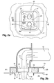
- the Figures 2a and 2b show a second variant of the first embodiment of the identification system according to the invention.
- the Figures 2a and 2b illustrate an installation in the vehicle of the heating, ventilation and air conditioning unit 20 bearing the identification system of the component 10 of the Figures 1a and 1b .
- connection interface 25 is placed at a separation wall 50 separating a passenger compartment 61 and a motor compartment 62 of the vehicle.
- the partition wall 50 has a passage 51 located substantially opposite the connection interface 25, to allow the passage of the pipes 41 and 42 of the thermodynamic air conditioning loop of the vehicle.
- the heating, ventilating and air conditioning unit 20 is mounted on the partition wall 50.
- a packer 52 is disposed between the heating, ventilating and air conditioning unit 20 and the partition wall 50 to ensure a sealed assembly and isolating the heating, ventilation and air conditioning unit 20 and the passenger compartment 61 from the engine compartment 62.
- FIGS. 3a and 3b show a first variant of a second embodiment of an identification system according to the invention.
- a second embodiment of the identification system of the component 10 comprising means for reading the identification reference 31 through a reading opening 32 formed in the connection interface 25.
- the identification reference 31 is carried by a support 30 placed substantially opposite the reading opening 32.
- Any type of support 30 may be envisaged, namely the component 10 itself, such as the faces, the tubes, the connection flanges, or an element added or not to the component, such as a label for example.
- a closure means 33 in particular a cache 33a.
- This cover 33a is held in the closed position by a fixing screw 34 which can be removed in order to disengage the cover 33a to read the identification reference 31 through the read opening 32.
- the Figures 4a and 4b show a second variant of the second embodiment of the identification system according to the invention.
- the Figures 4a and 4b show an installation in the vehicle of the heating, ventilation and air-conditioning unit 20 equivalent to that shown on the Figures 2a and 2b in relation to Figures 1a and 1 b.
- connection interface 25 is disposed in the immediate vicinity of the partition wall 50 between the passenger compartment 61 and the engine compartment 62 of the vehicle.
- the Figures 5a and 5b show a third variant of the second embodiment of the identification system according to the invention.
- the Figures 5a and 5b are a variant of the exemplary embodiment of Figures 4a and 4b .
- the closure means 33 of the reading aperture 32 is constituted by a shutter 32b, preferably forming an extension of the seal 52.
- the extension of the seal 52 is deformable material, including foam.
- the shutter 32b In order to be able to read the identification reference 31 through the reading aperture 32, the shutter 32b is deformed, for example with the finger or a tool, so as to disengage the reading aperture 32 for the time necessary to the reading of the identification reference 31. When the deformation action ceases, the shutter 32b returns to its original position thus ensuring its shutter function and sealing.
- FIGS. 6a and 6b show a fourth variant of the second embodiment of the identification system according to the invention.
- the Figures 6a and 6b constitute another alternative of the exemplary embodiment of Figures 4a and 4b .
- the closure means 33 of the reading aperture 32 comprises a cover 33c intended to cover the connection interface 25.
- the cover 33c can be mounted on the opening 51 of the partition wall 50.
- the cover 33c can be mounted on other forms of the heating, ventilation and air conditioning unit 20.
Landscapes
- Physics & Mathematics (AREA)
- Thermal Sciences (AREA)
- Engineering & Computer Science (AREA)
- Mechanical Engineering (AREA)
- Air-Conditioning For Vehicles (AREA)
- Air Conditioning Control Device (AREA)
Abstract
Description
- La présente invention concerne un système d'identification d'un composant intégré à un boîtier de chauffage, de ventilation et de climatisation permettant un traitement thermique d'un flux d'air. En particulier, le composant peut faire partie d'un circuit de traitement thermique d'un flux d'air.
- L'invention trouve une application particulièrement avantageuse dans le domaine des équipements de chauffage, de ventilation et de climatisation des véhicules automobiles.
- Il convient de préciser qu'on entend ici par « traitement thermique d'un flux d'air » l'ensemble des fonctions de chauffage, de ventilation et de climatisation, prises séparément et de façon unitaire ou en combinaison les unes avec les autres
- La plupart des véhicules automobiles sont généralement équipés d'un boîtier de chauffage, de ventilation et de climatisation permettant un traitement thermique d'un flux d'air.
- Un boîtier de chauffage, de ventilation et de climatisation est constitué d'une enceinte en matière plastique dans laquelle sont disposés les divers composants d'un circuit de traitement thermique d'un flux d'air destiné à être distribué dans un habitacle d'un véhicule automobile.
- Une turbine placée dans une entrée du boîtier de chauffage, de ventilation et de climatisation introduit dans le circuit de traitement thermique le flux d'air à traiter thermiquement provenant de l'extérieur du véhicule et/ou de l'habitacle. Le flux d'air est ensuite déshumidifié et refroidi au passage à travers un évaporateur relié, à l'extérieur du boîtier de chauffage, de ventilation et de climatisation, à une boucle thermodynamique de climatisation du véhicule dans lequel circule un fluide réfrigérant, notamment un fluide sur-critique, par exemple du dioxyde de carbone ou analogue, ou un fluide sous-critique, par exemple du R12 et R134A ou analogue.
- La boucle thermodynamique de climatisation comprend en complément de l'évaporateur classiquement un compresseur, un condenseur ou refroidisseur de gaz et un organe de détente.
- Le boîtier de chauffage, de ventilation et de climatisation comprend également un radiateur apte à réchauffer le flux d'air et faisant partie d'un circuit de refroidissement d'un moteur, en particulier un moteur thermique permettant la propulsion du véhicule.
- Le flux d'air ayant traversé l'évaporateur est séparé en un premier flux dirigé vers le radiateur et un deuxième flux d'air dirigé vers une branche d'air contournant le radiateur. Les premier et deuxième flux d'air se rejoignent dans une chambre de mélange afin d'obtenir un flux d'air à température désirée propre à être diffusé dans l'habitacle.
- La température du flux d'air distribué peut être ajustée en faisant varier des moyens de réglage, notamment des volets, modifiant la proportion des premier et deuxième flux d'air arrivant dans la chambre de mélange, ou en réglant la température du fluide d'échange thermique circulant dans le radiateur.
- Le flux d'air sortant de la chambre de mélange est finalement canalisé à travers différents conduits distribuant le flux d'air principalement vers le pare-brise, la planche de bord et vers les pieds des passagers avant et arrière du véhicule.
- Le boîtier de chauffage, de ventilation et de climatisation peut comprendre également, en amont ou en aval du pulseur, un filtre à air destiné à éliminer les pollens et autres particules, et éventuellement à désodoriser le flux d'air entrant dans le boîtier de chauffage, de ventilation et de climatisation.
- Les divers composants du circuit de traitement thermique du flux d'air sont placés à l'intérieur du boîtier de chauffage, de ventilation et de climatisation dans des emplacements prédéfinis par des empreintes réalisées en tant que logement pour les composants.
- Bien entendu, une même plateforme de véhicule est prévue pour recevoir un boîtier de chauffage, de ventilation et de climatisation défini, notamment en termes d'encombrement et de performances, indépendamment du type des composants qui y sont installés. Ainsi, par exemple, dans un boîtier de chauffage, de ventilation et de climatisation donné, peuvent être logés, dans une même empreinte, plusieurs types d'évaporateurs différant les uns des autres par leurs dimensions ou par la nature du fluide réfrigérant qu'ils utilisent.
- La difficulté qui se présente alors est qu'une fois que le composant, l'évaporateur notamment, est placé dans le boîtier de chauffage, de ventilation et de climatisation, il n'est plus possible de l'identifier sauf à démonter le boîtier de chauffage, de ventilation et de climatisation, ce qui représente une opération très pénalisante à réaliser, principalement quand le boîtier de chauffage, de ventilation et de climatisation est installé dans le véhicule.
- Or, certaines recommandations ou normes en vigueur exigent en particulier de pouvoir connaître le fluide utilisé dans les composants, notamment les composants fonctionnant avec du dioxyde de carbone. Actuellement, il ne peut être répondu à cette question qu'en démontant le boîtier de chauffage, de ventilation et de climatisation.
- Un but de l'invention est de proposer un système d'identification d'un composant d'un circuit de traitement thermique d'un flux d'air, le composant étant disposé à l'intérieur d'un boîtier de chauffage, de ventilation et de climatisation d'un véhicule automobile, permettant d'identifier le composant depuis l'extérieur du boîtier de chauffage, de ventilation et de climatisation sans avoir à le démonter.
- Ce but est atteint, conformément à l'invention, grâce à un système d'identification d'un composant d'un circuit de traitement thermique d'un flux d'air, le composant disposé à l'intérieur d'un boîtier de chauffage, de ventilation et de climatisation d'un véhicule automobile et raccordé à une boucle thermodynamique de climatisation de circulation d'un fluide réfrigérant à travers une interface de raccordement. Le système d'identification comprend une référence d'identification du composant et des moyens de lecture de la référence d'identification disposés à l'interface de raccordement.
- Le plus souvent, l'interface de raccordement est placée au niveau d'une paroi de séparation d'un habitacle et d'un compartiment moteur du véhicule.
- Dans une application particulière, le composant considéré est un évaporateur de la boucle thermodynamique de climatisation du véhicule, comprenant notamment un compresseur, un condenseur ou refroidisseur de gaz et un détendeur, ces éléments étant placés hors du boîtier de chauffage, de ventilation et de climatisation, généralement dans le compartiment moteur du véhicule.
- Selon un premier mode de réalisation de l'invention, les moyens de lecture comprennent une plaque de connexion portant la référence d'identification, la plaque de connexion étant destinée au raccordement du composant à la boucle thermodynamique de climatisation de circulation du fluide réfrigérant.
- Selon un deuxième mode de réalisation de l'invention, les moyens de lecture comprennent une ouverture de lecture ménagée à l'interface de raccordement, le système d'identification comprenant en outre des moyens d'obturation de l'ouverture de lecture.
- Plusieurs variantes de réalisation peuvent être envisagées pour les moyens d'obturation de l'ouverture de lecture. Ainsi, les moyens d'obturation comprennent un cache et/ou un obturateur respectivement disposé dans l'ouverture de lecture et/ou un capot recouvrant l'interface de raccordement.
- La description qui va suivre en regard des dessins annexés, donnés à titre d'exemples non limitatifs, fera bien comprendre en quoi consiste l'invention et comment elle peut être réalisée. Notamment, les figures annexées représentent sur :
- la
figure 1a , une vue d'un premier mode de réalisation d'un système d'identification selon la présente l'invention, - la
figure 1b , une vue en coupe selon l'axe X du système d'identification de lafigure 1a . - la
figure 2a , est une vue d'une deuxième variante du premier mode de réalisation du système d'identification desfigures 1a et 1b , - la
figure 2b , une vue en coupe selon l'axe X du système d'identification de lafigure 2a , - la
figure 3a , une vue d'un deuxième mode de réalisation d'un système d'identification selon la présente, - la
figure 3b , une vue en coupe selon l'axe X du système d'identification de lafigure 3a , - la
figure 4a , une vue d'une deuxième variante du deuxième mode de réalisation du système d'identification desfigures 3a et 3b , - la
figure 4b , une vue en coupe selon l'axe X du système d'identification de lafigure 4a , - la
figure 5a , une vue d'une troisième variante du deuxième mode de réalisation du système d'identification desfigures 3a et 3b , - la
figure 5b , une vue en coupe selon l'axe X du système d'identification de lafigure 5a , - la
figure 6a , une vue d'une quatrième variante du deuxième mode de réalisation du système d'identification desfigures 3a et 3b , et - la
figure 6b , une vue en coupe selon l'axe X du système d'identification de lafigure 6a . - Les
figures 1a et 1b présentent une première variante d'un premier mode de réalisation d'un système d'identification conforme à l'invention. Sur lesfigures 1a et 1b , est représenté un boîtier de chauffage, de ventilation et de climatisation 20 d'un véhicule automobile dans lequel est disposé un composant 10 intégré dans le boîtier de chauffage, de ventilation et de climatisation 20. - Le composant 10 est notamment un élément d'un circuit de traitement thermique d'un flux d'air. Dans un tel cas, le composant 10 peut en particulier être un évaporateur d'une boucle thermodynamique de climatisation du véhicule.
- Bien entendu, d'autres composants peuvent être envisagés dans le cadre de l'invention, notamment le radiateur du circuit de traitement thermique du flux d'air intégré dans le boîtier de chauffage, de ventilation et de climatisation 20 et permettant le traitement thermique du flux d'air.
- De manière à satisfaire des exigences normatives relatives imposant de pouvoir identifier certains organes ou composants depuis l'extérieur du boîtier de chauffage, de ventilation et de climatisation 20, en particulier le composant 10 tel que l'évaporateur, selon la présente invention, il est prévu un système d'identification qui va maintenant être décrit en détail.
- Comme on peut le voir sur les
figures 1a et 1b , le système d'identification comprend plusieurs éléments. Selon la présente invention, le système d'identification intègre au moins une référence d'identification 31 portant les indications utiles concernant le composant 10. En particulier, ces indications utiles sont la nature du fluide réfrigérant, la référence du composant, etc. - Selon le premier mode de réalisation, le système d'identification intègre au moins un moyen de lecture de la référence d'identification 31 disposés à l'interface de raccordement 25 du composant 10 avec la boucle thermodynamique de climatisation du véhicule dans lequel circule un fluide réfrigérant, notamment un fluide sur-critique, par exemple du dioxyde de carbone ou analogue, ou un fluide sous-critique, par exemple du R12 et R134A ou analogue.
- A titre d'exemple, le composant 10 est un évaporateur intégré à la boucle thermodynamique de climatisation comprenant classiquement un compresseur, un condenseur ou refroidisseur de gaz et un organe de détente.
- L'interface de raccordement 25 est agencé dans un orifice 22 pratiqué dans une paroi 21 du boîtier de chauffage, de ventilation et de climatisation 20 de manière à raccorder le composant 10 situé à l'intérieur du boîtier de chauffage, de ventilation et de climatisation 20 à la boucle thermodynamique de climatisation située à l'extérieur du boîtier de chauffage, de ventilation et de climatisation 20.
- Dans le mode de réalisation des
figures 1a et 1b , l'interface de raccordement 25 comporte une plaque de connexion 23 portant la référence d'identification 31. La plaque de connexion 23 est par ailleurs destinée au raccordement de tuyaux d'entrée 11 et de sortie 12 du composant 10 à deux tubulures 41 et 42 de la boucle thermodynamique de climatisation du véhicule. Les tuyaux d'entrée 11 et de sortie 12 du composant 10 sont reliées entre elles par la plaque de connexion 23. - De façon préférentielle, un joint d'étanchéité 24 est disposé entre la plaque de connexion 23 et l'orifice 22 pratiqué dans une paroi 21 du boîtier de chauffage, de ventilation et de climatisation 20 afin d'assurer l'étanchéité du boîtier de chauffage, de ventilation et de climatisation 20 par rapport au milieu extérieur.
- Préférentiellement, les tubulures 41 et 42 de la boucle thermodynamique de climatisation du véhicule sont reliées entre elles par une bride de connexion 45. Ainsi, la connexion des tuyaux d'entrée 11 et de sortie 12 du composant 10 se fait en connectant entre elles la plaque de connexion 23 et la bride de connexion 45.
- Selon le premier mode de réalisation, la référence d'identification 31 est portée par la plaque de connexion 23. La référence d'identification 31 est donc visible à travers l'orifice 22 de passage de l'interface de raccordement 25. Une telle lecture de la référence d'identification 31 peut donc être réalisée depuis l'extérieur du boîtier de chauffage, de ventilation et de climatisation 20, notamment depuis un compartiment moteur du véhicule, un espace dédiée à la maintenance, etc.
- Dans la suite de la description, de nombreux éléments des figures précédentes sont repris dans les exemples suivants. En conséquence, sauf indication contraire, ces éléments seront identifiés par la même référence et ont les mêmes structures et caractéristiques.
- Les
figures 2a et 2b présentent une deuxième variante du premier mode de réalisation du système d'identification conforme à l'invention. Lesfigures 2a et 2b illustrent une implantation dans le véhicule du boîtier de chauffage, de ventilation et de climatisation 20 portant le système d'identification du composant 10 desfigures 1a et 1b . - Selon ce mode d'implémentation, l'interface de raccordement 25 est placée au niveau d'une paroi de séparation 50 séparant un habitacle 61 et un compartiment moteur 62 du véhicule. Comme on peut le voir sur la
figure 2b , la paroi de séparation 50 présente un passage 51 située sensiblement en regard de l'interface de raccordement 25, afin de permettre le passage des tubulures 41 et 42 de la boucle thermodynamique de climatisation du véhicule. - Le boîtier de chauffage, de ventilation et de climatisation 20 est monté sur la paroi de séparation 50. Une garniture d'étanchéité 52 est disposée entre le boîtier de chauffage, de ventilation et de climatisation 20 et la paroi de séparation 50 afin d'assurer un montage étanche et isoler le boîtier de chauffage, de ventilation et de climatisation 20 et l'habitacle 61 du compartiment moteur 62.
- Les
figures 3a et 3b présentent une première variante d'un deuxième mode de réalisation d'un système d'identification conforme à l'invention. Sur lesfigures 3a et 3b , est représenté un deuxième mode de réalisation du système d'identification du composant 10 comprenant des moyens de lecture de la référence d'identification 31 à travers une ouverture de lecture 32 ménagée dans l'interface de raccordement 25. - Selon cet exemple de réalisation, la référence d'identification 31 est portée par un support 30 placé sensiblement en regard de l'ouverture de lecture 32. Tout type de support 30 peut être envisagé, à savoir le composant 10 lui-même, comme les faces, les tubes, les brides de connexion, ou un élément rapporté ou non sur le composant, tel qu'une étiquette par exemple.
- De manière à garantir une étanchéité du boîtier de chauffage, de ventilation et de climatisation 20 par rapport au compartiment moteur 62, il est prévu de clore l'ouverture de lecture 32 par un moyen d'obturation 33, en particulier un cache 33a. Ce cache 33a est maintenu en position d'obturation par une vis de fixation 34 qui peut être retirée afin de dégager le cache 33a pour lire la référence d'identification 31 à travers l'ouverture de lecture 32.
- Les
figures 4a et 4b présentent une deuxième variante du deuxième mode de réalisation du système d'identification conforme à l'invention. Lesfigures 4a et 4b montrent une implantation dans le véhicule du boîtier chauffage, de ventilation et de climatisation 20 équivalent à celui représenté sur lesfigures 2a et 2b en relation avec lesfigures 1a et 1 b. - Ainsi, l'interface de raccordement 25 est disposée à proximité immédiate de la paroi de séparation 50 entre l'habitacle 61 et le compartiment moteur 62 du véhicule.
- Les
figures 5a et 5b présentent une troisième variante du deuxième mode de réalisation du système d'identification conforme à l'invention. Lesfigures 5a et 5b sont une variante de l'exemple de réalisation desfigures 4a et 4b . - Selon cette alternative, le moyen d'obturation 33 de l'ouverture de lecture 32 est constitué par un obturateur 32b, formant de façon préférentielle, une extension de la garniture d'étanchéité 52.
- De façon préférentielle, l'extension de la garniture d'étanchéité 52 est en matériau déformable, notamment de la mousse.
- Afin de pouvoir lire la référence d'identification 31 à travers l'ouverture de lecture 32, l'obturateur 32b est déformée, par exemple avec le doigt ou un outil, de manière à dégager l'ouverture de lecture 32 pendant le temps nécessaire à la lecture de la référence d'identification 31. Lorsque l'action de déformation cesse, l'obturateur 32b revient dans sa positon d'origine assurant ainsi sa fonction d'obturation et d'étanchéité.
- Les
figures 6a et 6b présentent une quatrième variante du deuxième mode de réalisation du système d'identification conforme à l'invention. Lesfigures 6a et 6b constituent une autre alternative de l'exemple de réalisation desfigures 4a et 4b . - Selon cette variante, le moyen d'obturation 33 de l'ouverture de lecture 32 comprend un capot 33c destiné à couvrir l'interface de raccordement 25. En pratique, le capot 33c peut être monté sur l'ouverture 51 de la paroi de séparation 50.
- Selon des alternatives de réalisation non représentées, le capot 33c peut être monté sur d'autres formes du boîtier de chauffage, de ventilation et de climatisation 20.
- Bien évidemment, l'invention n'est pas limitée aux modes de réalisation décrits précédemment et fournis uniquement à titre d'exemple et englobe d'autres variantes que pourra envisager l'homme du métier dans le cadre de la présente invention et notamment toutes combinaisons des différents modes de réalisation décrits précédemment.
Claims (9)
- Système d'identification d'un composant (10) d'un circuit de traitement thermique d'un flux d'air, le composant (10) étant disposé à l'intérieur d'un boîtier de chauffage, de ventilation et de climatisation (20) d'un véhicule automobile et raccordé à une boucle thermodynamique de climatisation de circulation d'un fluide réfrigérant à travers une interface de raccordement (25), caractérisé en ce que le système d'identification comprend :- une référence d'identification (31) du composant (10) et- des moyens de lecture (23, 32) de la référence d'identification (31), disposés à l'interface de raccordement (25).
- Système d'identification selon la revendication 1, dans lequel les moyens de lecture comprennent une plaque de connexion (23) portant la référence d'identification (31), la plaque de connexion (23) étant destinée au raccordement du composant (10) à la boucle thermodynamique de climatisation de circulation du fluide réfrigérant.
- Système d'identification selon la revendication 1 ou 2, dans lequel les moyens de lecture comprennent une ouverture de lecture (32) ménagée à l'interface de raccordement (25), le système d'identification comprenant en outre des moyens d'obturation (33, 33a, 33b) de l'ouverture de lecture (32).
- Système d'identification selon la revendication 3, dans lequel les moyens d'obturation (33) comprennent un cache (33a) agencé dans l'ouverture de lecture (32).
- Système d'identification selon la revendication 3 ou 4, dans lequel les moyens d'obturation (33) comprennent un obturateur (32b) en matériau déformable, notamment en mousse disposé dans l'ouverture de lecture (32).
- Système d'identification selon l'une des revendications 3 à 5, dans lequel les moyens d'obturation (33) comprennent un capot (33c) recouvrant l'interface de raccordement (25).
- Système d'identification selon l'une quelconque des revendications 1 à 6, dans lequel l'interface de raccordement (25) est placée au niveau d'une paroi de séparation (50) entre un habitacle (61) et un compartiment moteur (62) du véhicule.
- Système d'identification selon l'une quelconque des revendications 1 à 7, dans lequel le composant (10) est un évaporateur de la boucle thermodynamique de climatisation de circulation d'un fluide réfrigérant.
- Système d'identification selon l'une des revendications précédéentes, dans lequel le fluide réfrigérant est le dioxyde de carbone.
Applications Claiming Priority (1)
| Application Number | Priority Date | Filing Date | Title |
|---|---|---|---|
| FR0806145A FR2937907B1 (fr) | 2008-11-04 | 2008-11-04 | Systeme d'identification d'un composant d'un circuit de traitement thermique d'un flux d'air. |
Publications (2)
| Publication Number | Publication Date |
|---|---|
| EP2181873A1 true EP2181873A1 (fr) | 2010-05-05 |
| EP2181873B1 EP2181873B1 (fr) | 2012-07-11 |
Family
ID=40740177
Family Applications (1)
| Application Number | Title | Priority Date | Filing Date |
|---|---|---|---|
| EP20090174802 Active EP2181873B1 (fr) | 2008-11-04 | 2009-11-02 | Système d'identification d'un composant d'un circuit de traitement thermique d'un flux d'air |
Country Status (3)
| Country | Link |
|---|---|
| EP (1) | EP2181873B1 (fr) |
| ES (1) | ES2391001T3 (fr) |
| FR (1) | FR2937907B1 (fr) |
Citations (3)
| Publication number | Priority date | Publication date | Assignee | Title |
|---|---|---|---|---|
| US6722152B1 (en) * | 2003-05-05 | 2004-04-20 | Carrier Corporation | Fresh air intake filter and multi function grill |
| EP1502642A1 (fr) * | 2003-07-28 | 2005-02-02 | Behr GmbH & Co. KG | Dispositif de filtre |
| FR2865159A1 (fr) * | 2004-01-21 | 2005-07-22 | Valeo Climatisation | Dispositif d'obturation d'une installation de ventilation, chauffage et/ou climatisation facilitant l'acces a un moyen de filtration. |
-
2008
- 2008-11-04 FR FR0806145A patent/FR2937907B1/fr not_active Expired - Fee Related
-
2009
- 2009-11-02 ES ES09174802T patent/ES2391001T3/es active Active
- 2009-11-02 EP EP20090174802 patent/EP2181873B1/fr active Active
Patent Citations (3)
| Publication number | Priority date | Publication date | Assignee | Title |
|---|---|---|---|---|
| US6722152B1 (en) * | 2003-05-05 | 2004-04-20 | Carrier Corporation | Fresh air intake filter and multi function grill |
| EP1502642A1 (fr) * | 2003-07-28 | 2005-02-02 | Behr GmbH & Co. KG | Dispositif de filtre |
| FR2865159A1 (fr) * | 2004-01-21 | 2005-07-22 | Valeo Climatisation | Dispositif d'obturation d'une installation de ventilation, chauffage et/ou climatisation facilitant l'acces a un moyen de filtration. |
Also Published As
| Publication number | Publication date |
|---|---|
| FR2937907B1 (fr) | 2010-12-17 |
| EP2181873B1 (fr) | 2012-07-11 |
| FR2937907A1 (fr) | 2010-05-07 |
| ES2391001T3 (es) | 2012-11-20 |
Similar Documents
| Publication | Publication Date | Title |
|---|---|---|
| EP2335953B1 (fr) | Système de climatisation comprenant un support porteur d'éléments constitutifs dudit système | |
| EP2889168B1 (fr) | Dispositif de chauffage, ventilation et/ou climatisation | |
| EP1764245B1 (fr) | Appareil de chauffage, ventilation et/ou clilmatisation à acoustique améliorée | |
| FR2931102A1 (fr) | Appareil et installation de chauffage, ventilation, et/ou de climatisation d'un vehicule automobile | |
| EP1609639B1 (fr) | Boîtier à étanchéité du type "labyrinthe", pour une installation de chauffage, ventilation et/ou climatisation d'habitacle | |
| EP2181873B1 (fr) | Système d'identification d'un composant d'un circuit de traitement thermique d'un flux d'air | |
| FR2991635A1 (fr) | Installation de conditionnement thermique d'un habitacle d'un vehicule, notamment un vehicule electrique. | |
| EP3847045B1 (fr) | Véhicule automobile comprenant un dispositif de chauffage, ventilation et/ou climatisation | |
| EP2181871B1 (fr) | Système d'identification d'un composant d'un circuit de traitement thermique d'un flux d'air | |
| EP2154013B1 (fr) | Appareil de chauffage, ventilation et/ou climatisation à acoustique améliorée | |
| FR3070317A1 (fr) | Dispositif de chauffage, ventilation et/ou climatisation pour vehicule automobile | |
| WO2019224455A1 (fr) | Boitier pour un appareil de chauffage, ventilation et/ou climatisation pour vehicule automobile | |
| FR2987787A1 (fr) | Installation de chauffage, ventilation et/ou climatisation pour un habitacle de vehicule automobile | |
| FR2991634A1 (fr) | Systeme de conditionnement thermique d'un habitacle d'un vehicule, notamment un vehicule electrique. | |
| EP1276625B1 (fr) | Dispositif de regulation du debit d'un flux d'air circulant sous un capot de vehicule automobile | |
| FR2854349A1 (fr) | Boite d'admission d'air munie d'un capteur de mesure de l'air pour appareil de ventilation, de chauffage et/ou de climatisation d'un habitacle de vehicule | |
| EP3481655A1 (fr) | Dispositif de chauffage, ventilation et/ou climatisation pour vehicule automobile | |
| WO2015059131A1 (fr) | Système de ventilation, de chauffage et/ou de climatisation de véhicule automobile | |
| EP3061634B1 (fr) | Dispositif de chauffage, ventilation et/ou climatisation pour véhicule automobile | |
| EP3990762A1 (fr) | Dispositif de regulation d'un flux d'air pour une entree d'air d'un vehicule automobile | |
| FR3036784A1 (fr) | Boucle de climatisation reversible et installation de climatisation reversible integrant une telle boucle | |
| EP2554412A1 (fr) | Appareil de chauffage, ventilation et/ou climatisation à encombrement réduit. | |
| FR2908181A1 (fr) | Dispositif de traitement de l'air avec moyens d'assemblage | |
| EP2878467B1 (fr) | Dispositif conducteur d'air concu pour le maintien d'un radiateur de chauffage automobile et son etancheite | |
| FR3162392A1 (fr) | Aérateur comprenant une soupape à ressort pour la réduction de pertes de charges |
Legal Events
| Date | Code | Title | Description |
|---|---|---|---|
| PUAI | Public reference made under article 153(3) epc to a published international application that has entered the european phase |
Free format text: ORIGINAL CODE: 0009012 |
|
| AK | Designated contracting states |
Kind code of ref document: A1 Designated state(s): AT BE BG CH CY CZ DE DK EE ES FI FR GB GR HR HU IE IS IT LI LT LU LV MC MK MT NL NO PL PT RO SE SI SK SM TR |
|
| AX | Request for extension of the european patent |
Extension state: AL BA RS |
|
| 17P | Request for examination filed |
Effective date: 20101028 |
|
| 17Q | First examination report despatched |
Effective date: 20101124 |
|
| R17P | Request for examination filed (corrected) |
Effective date: 20101019 |
|
| GRAP | Despatch of communication of intention to grant a patent |
Free format text: ORIGINAL CODE: EPIDOSNIGR1 |
|
| GRAS | Grant fee paid |
Free format text: ORIGINAL CODE: EPIDOSNIGR3 |
|
| GRAA | (expected) grant |
Free format text: ORIGINAL CODE: 0009210 |
|
| AK | Designated contracting states |
Kind code of ref document: B1 Designated state(s): AT BE BG CH CY CZ DE DK EE ES FI FR GB GR HR HU IE IS IT LI LT LU LV MC MK MT NL NO PL PT RO SE SI SK SM TR |
|
| REG | Reference to a national code |
Ref country code: GB Ref legal event code: FG4D Free format text: NOT ENGLISH |
|
| REG | Reference to a national code |
Ref country code: CH Ref legal event code: EP |
|
| REG | Reference to a national code |
Ref country code: AT Ref legal event code: REF Ref document number: 565907 Country of ref document: AT Kind code of ref document: T Effective date: 20120715 |
|
| REG | Reference to a national code |
Ref country code: IE Ref legal event code: FG4D Free format text: LANGUAGE OF EP DOCUMENT: FRENCH |
|
| REG | Reference to a national code |
Ref country code: DE Ref legal event code: R096 Ref document number: 602009008179 Country of ref document: DE Effective date: 20120906 |
|
| REG | Reference to a national code |
Ref country code: ES Ref legal event code: FG2A Ref document number: 2391001 Country of ref document: ES Kind code of ref document: T3 Effective date: 20121120 |
|
| REG | Reference to a national code |
Ref country code: NL Ref legal event code: VDEP Effective date: 20120711 |
|
| REG | Reference to a national code |
Ref country code: AT Ref legal event code: MK05 Ref document number: 565907 Country of ref document: AT Kind code of ref document: T Effective date: 20120711 |
|
| REG | Reference to a national code |
Ref country code: LT Ref legal event code: MG4D Effective date: 20120711 |
|
| PG25 | Lapsed in a contracting state [announced via postgrant information from national office to epo] |
Ref country code: CY Free format text: LAPSE BECAUSE OF FAILURE TO SUBMIT A TRANSLATION OF THE DESCRIPTION OR TO PAY THE FEE WITHIN THE PRESCRIBED TIME-LIMIT Effective date: 20120711 Ref country code: AT Free format text: LAPSE BECAUSE OF FAILURE TO SUBMIT A TRANSLATION OF THE DESCRIPTION OR TO PAY THE FEE WITHIN THE PRESCRIBED TIME-LIMIT Effective date: 20120711 Ref country code: NO Free format text: LAPSE BECAUSE OF FAILURE TO SUBMIT A TRANSLATION OF THE DESCRIPTION OR TO PAY THE FEE WITHIN THE PRESCRIBED TIME-LIMIT Effective date: 20121011 Ref country code: IS Free format text: LAPSE BECAUSE OF FAILURE TO SUBMIT A TRANSLATION OF THE DESCRIPTION OR TO PAY THE FEE WITHIN THE PRESCRIBED TIME-LIMIT Effective date: 20121111 Ref country code: HR Free format text: LAPSE BECAUSE OF FAILURE TO SUBMIT A TRANSLATION OF THE DESCRIPTION OR TO PAY THE FEE WITHIN THE PRESCRIBED TIME-LIMIT Effective date: 20120711 Ref country code: LT Free format text: LAPSE BECAUSE OF FAILURE TO SUBMIT A TRANSLATION OF THE DESCRIPTION OR TO PAY THE FEE WITHIN THE PRESCRIBED TIME-LIMIT Effective date: 20120711 Ref country code: FI Free format text: LAPSE BECAUSE OF FAILURE TO SUBMIT A TRANSLATION OF THE DESCRIPTION OR TO PAY THE FEE WITHIN THE PRESCRIBED TIME-LIMIT Effective date: 20120711 |
|
| PG25 | Lapsed in a contracting state [announced via postgrant information from national office to epo] |
Ref country code: PT Free format text: LAPSE BECAUSE OF FAILURE TO SUBMIT A TRANSLATION OF THE DESCRIPTION OR TO PAY THE FEE WITHIN THE PRESCRIBED TIME-LIMIT Effective date: 20121112 Ref country code: LV Free format text: LAPSE BECAUSE OF FAILURE TO SUBMIT A TRANSLATION OF THE DESCRIPTION OR TO PAY THE FEE WITHIN THE PRESCRIBED TIME-LIMIT Effective date: 20120711 Ref country code: GR Free format text: LAPSE BECAUSE OF FAILURE TO SUBMIT A TRANSLATION OF THE DESCRIPTION OR TO PAY THE FEE WITHIN THE PRESCRIBED TIME-LIMIT Effective date: 20121012 Ref country code: SE Free format text: LAPSE BECAUSE OF FAILURE TO SUBMIT A TRANSLATION OF THE DESCRIPTION OR TO PAY THE FEE WITHIN THE PRESCRIBED TIME-LIMIT Effective date: 20120711 Ref country code: SI Free format text: LAPSE BECAUSE OF FAILURE TO SUBMIT A TRANSLATION OF THE DESCRIPTION OR TO PAY THE FEE WITHIN THE PRESCRIBED TIME-LIMIT Effective date: 20120711 Ref country code: PL Free format text: LAPSE BECAUSE OF FAILURE TO SUBMIT A TRANSLATION OF THE DESCRIPTION OR TO PAY THE FEE WITHIN THE PRESCRIBED TIME-LIMIT Effective date: 20120711 |
|
| PG25 | Lapsed in a contracting state [announced via postgrant information from national office to epo] |
Ref country code: NL Free format text: LAPSE BECAUSE OF FAILURE TO SUBMIT A TRANSLATION OF THE DESCRIPTION OR TO PAY THE FEE WITHIN THE PRESCRIBED TIME-LIMIT Effective date: 20120711 |
|
| PG25 | Lapsed in a contracting state [announced via postgrant information from national office to epo] |
Ref country code: DK Free format text: LAPSE BECAUSE OF FAILURE TO SUBMIT A TRANSLATION OF THE DESCRIPTION OR TO PAY THE FEE WITHIN THE PRESCRIBED TIME-LIMIT Effective date: 20120711 Ref country code: EE Free format text: LAPSE BECAUSE OF FAILURE TO SUBMIT A TRANSLATION OF THE DESCRIPTION OR TO PAY THE FEE WITHIN THE PRESCRIBED TIME-LIMIT Effective date: 20120711 Ref country code: RO Free format text: LAPSE BECAUSE OF FAILURE TO SUBMIT A TRANSLATION OF THE DESCRIPTION OR TO PAY THE FEE WITHIN THE PRESCRIBED TIME-LIMIT Effective date: 20120711 |
|
| PLBE | No opposition filed within time limit |
Free format text: ORIGINAL CODE: 0009261 |
|
| STAA | Information on the status of an ep patent application or granted ep patent |
Free format text: STATUS: NO OPPOSITION FILED WITHIN TIME LIMIT |
|
| BERE | Be: lapsed |
Owner name: VALEO SYSTEMES THERMIQUES Effective date: 20121130 |
|
| PG25 | Lapsed in a contracting state [announced via postgrant information from national office to epo] |
Ref country code: SK Free format text: LAPSE BECAUSE OF FAILURE TO SUBMIT A TRANSLATION OF THE DESCRIPTION OR TO PAY THE FEE WITHIN THE PRESCRIBED TIME-LIMIT Effective date: 20120711 |
|
| 26N | No opposition filed |
Effective date: 20130412 |
|
| PG25 | Lapsed in a contracting state [announced via postgrant information from national office to epo] |
Ref country code: BG Free format text: LAPSE BECAUSE OF FAILURE TO SUBMIT A TRANSLATION OF THE DESCRIPTION OR TO PAY THE FEE WITHIN THE PRESCRIBED TIME-LIMIT Effective date: 20121011 |
|
| REG | Reference to a national code |
Ref country code: DE Ref legal event code: R097 Ref document number: 602009008179 Country of ref document: DE Effective date: 20130412 |
|
| REG | Reference to a national code |
Ref country code: IE Ref legal event code: MM4A |
|
| PG25 | Lapsed in a contracting state [announced via postgrant information from national office to epo] |
Ref country code: BE Free format text: LAPSE BECAUSE OF NON-PAYMENT OF DUE FEES Effective date: 20121130 |
|
| PG25 | Lapsed in a contracting state [announced via postgrant information from national office to epo] |
Ref country code: IE Free format text: LAPSE BECAUSE OF NON-PAYMENT OF DUE FEES Effective date: 20121102 |
|
| PG25 | Lapsed in a contracting state [announced via postgrant information from national office to epo] |
Ref country code: MT Free format text: LAPSE BECAUSE OF FAILURE TO SUBMIT A TRANSLATION OF THE DESCRIPTION OR TO PAY THE FEE WITHIN THE PRESCRIBED TIME-LIMIT Effective date: 20120711 |
|
| PG25 | Lapsed in a contracting state [announced via postgrant information from national office to epo] |
Ref country code: TR Free format text: LAPSE BECAUSE OF FAILURE TO SUBMIT A TRANSLATION OF THE DESCRIPTION OR TO PAY THE FEE WITHIN THE PRESCRIBED TIME-LIMIT Effective date: 20120711 Ref country code: MC Free format text: LAPSE BECAUSE OF NON-PAYMENT OF DUE FEES Effective date: 20121130 |
|
| PG25 | Lapsed in a contracting state [announced via postgrant information from national office to epo] |
Ref country code: SM Free format text: LAPSE BECAUSE OF FAILURE TO SUBMIT A TRANSLATION OF THE DESCRIPTION OR TO PAY THE FEE WITHIN THE PRESCRIBED TIME-LIMIT Effective date: 20120711 Ref country code: LU Free format text: LAPSE BECAUSE OF NON-PAYMENT OF DUE FEES Effective date: 20121102 |
|
| REG | Reference to a national code |
Ref country code: CH Ref legal event code: PL |
|
| GBPC | Gb: european patent ceased through non-payment of renewal fee |
Effective date: 20131102 |
|
| PG25 | Lapsed in a contracting state [announced via postgrant information from national office to epo] |
Ref country code: HU Free format text: LAPSE BECAUSE OF FAILURE TO SUBMIT A TRANSLATION OF THE DESCRIPTION OR TO PAY THE FEE WITHIN THE PRESCRIBED TIME-LIMIT Effective date: 20091102 Ref country code: CH Free format text: LAPSE BECAUSE OF NON-PAYMENT OF DUE FEES Effective date: 20131130 Ref country code: LI Free format text: LAPSE BECAUSE OF NON-PAYMENT OF DUE FEES Effective date: 20131130 |
|
| PG25 | Lapsed in a contracting state [announced via postgrant information from national office to epo] |
Ref country code: GB Free format text: LAPSE BECAUSE OF NON-PAYMENT OF DUE FEES Effective date: 20131102 |
|
| PG25 | Lapsed in a contracting state [announced via postgrant information from national office to epo] |
Ref country code: MK Free format text: LAPSE BECAUSE OF FAILURE TO SUBMIT A TRANSLATION OF THE DESCRIPTION OR TO PAY THE FEE WITHIN THE PRESCRIBED TIME-LIMIT Effective date: 20120711 |
|
| REG | Reference to a national code |
Ref country code: FR Ref legal event code: PLFP Year of fee payment: 7 |
|
| REG | Reference to a national code |
Ref country code: FR Ref legal event code: PLFP Year of fee payment: 8 |
|
| REG | Reference to a national code |
Ref country code: FR Ref legal event code: PLFP Year of fee payment: 9 |
|
| PGFP | Annual fee paid to national office [announced via postgrant information from national office to epo] |
Ref country code: CZ Payment date: 20211018 Year of fee payment: 13 Ref country code: ES Payment date: 20211203 Year of fee payment: 13 |
|
| PGFP | Annual fee paid to national office [announced via postgrant information from national office to epo] |
Ref country code: IT Payment date: 20211110 Year of fee payment: 13 |
|
| P01 | Opt-out of the competence of the unified patent court (upc) registered |
Effective date: 20230528 |
|
| PG25 | Lapsed in a contracting state [announced via postgrant information from national office to epo] |
Ref country code: CZ Free format text: LAPSE BECAUSE OF NON-PAYMENT OF DUE FEES Effective date: 20221102 |
|
| PG25 | Lapsed in a contracting state [announced via postgrant information from national office to epo] |
Ref country code: IT Free format text: LAPSE BECAUSE OF NON-PAYMENT OF DUE FEES Effective date: 20221102 |
|
| REG | Reference to a national code |
Ref country code: ES Ref legal event code: FD2A Effective date: 20231227 |
|
| PG25 | Lapsed in a contracting state [announced via postgrant information from national office to epo] |
Ref country code: ES Free format text: LAPSE BECAUSE OF NON-PAYMENT OF DUE FEES Effective date: 20221103 |
|
| PG25 | Lapsed in a contracting state [announced via postgrant information from national office to epo] |
Ref country code: ES Free format text: LAPSE BECAUSE OF NON-PAYMENT OF DUE FEES Effective date: 20221103 |
|
| PGFP | Annual fee paid to national office [announced via postgrant information from national office to epo] |
Ref country code: DE Payment date: 20251117 Year of fee payment: 17 |
|
| PGFP | Annual fee paid to national office [announced via postgrant information from national office to epo] |
Ref country code: FR Payment date: 20251128 Year of fee payment: 17 |