EP2181333B1 - Erkennungsverfahren und -systeme - Google Patents
Erkennungsverfahren und -systeme Download PDFInfo
- Publication number
- EP2181333B1 EP2181333B1 EP08789360A EP08789360A EP2181333B1 EP 2181333 B1 EP2181333 B1 EP 2181333B1 EP 08789360 A EP08789360 A EP 08789360A EP 08789360 A EP08789360 A EP 08789360A EP 2181333 B1 EP2181333 B1 EP 2181333B1
- Authority
- EP
- European Patent Office
- Prior art keywords
- reagent
- sample fluid
- carrier surface
- sensor
- detection region
- Prior art date
- Legal status (The legal status is an assumption and is not a legal conclusion. Google has not performed a legal analysis and makes no representation as to the accuracy of the status listed.)
- Active
Links
Images


Classifications
-
- G—PHYSICS
- G01—MEASURING; TESTING
- G01N—INVESTIGATING OR ANALYSING MATERIALS BY DETERMINING THEIR CHEMICAL OR PHYSICAL PROPERTIES
- G01N33/00—Investigating or analysing materials by specific methods not covered by groups G01N1/00 - G01N31/00
- G01N33/48—Biological material, e.g. blood, urine; Haemocytometers
- G01N33/50—Chemical analysis of biological material, e.g. blood, urine; Testing involving biospecific ligand binding methods; Immunological testing
- G01N33/53—Immunoassay; Biospecific binding assay; Materials therefor
- G01N33/543—Immunoassay; Biospecific binding assay; Materials therefor with an insoluble carrier for immobilising immunochemicals
- G01N33/54366—Apparatus specially adapted for solid-phase testing
-
- G—PHYSICS
- G01—MEASURING; TESTING
- G01N—INVESTIGATING OR ANALYSING MATERIALS BY DETERMINING THEIR CHEMICAL OR PHYSICAL PROPERTIES
- G01N27/00—Investigating or analysing materials by the use of electric, electrochemical, or magnetic means
- G01N27/72—Investigating or analysing materials by the use of electric, electrochemical, or magnetic means by investigating magnetic variables
- G01N27/74—Investigating or analysing materials by the use of electric, electrochemical, or magnetic means by investigating magnetic variables of fluids
- G01N27/745—Investigating or analysing materials by the use of electric, electrochemical, or magnetic means by investigating magnetic variables of fluids for detecting magnetic beads used in biochemical assays
-
- Y—GENERAL TAGGING OF NEW TECHNOLOGICAL DEVELOPMENTS; GENERAL TAGGING OF CROSS-SECTIONAL TECHNOLOGIES SPANNING OVER SEVERAL SECTIONS OF THE IPC; TECHNICAL SUBJECTS COVERED BY FORMER USPC CROSS-REFERENCE ART COLLECTIONS [XRACs] AND DIGESTS
- Y10—TECHNICAL SUBJECTS COVERED BY FORMER USPC
- Y10T—TECHNICAL SUBJECTS COVERED BY FORMER US CLASSIFICATION
- Y10T29/00—Metal working
- Y10T29/49—Method of mechanical manufacture
- Y10T29/49826—Assembling or joining
- Y10T29/49885—Assembling or joining with coating before or during assembling
Definitions
- the present invention relates to the field of biosensors. More particularly, the present invention relates to methods and systems for obtaining devices for detecting the presence of an analyte, e.g. for qualitative or quantitative detection of biological, chemical or biochemical entities.
- Biosensors are devices that allow qualitative or quantitative detection of target molecules, also called “analytes", such as e.g. proteins, viruses, bacteria, cell components, cell membranes, spores, DNA, RNA, etc. in a sample fluid comprising for example blood, serum, plasma, saliva, tissue extract, intestinal fluid, cell culture extract, food or feed extract, drinking water, etc.
- a biosensor uses a sensor surface that comprises specific recognition elements for capturing the analyte.
- the surface of the biosensor device may therefore be modified by attaching specific molecules to it, which are suitable to bind the target molecules to be detected in the sample fluid.
- a well established principle is the counting of labelled molecules of interest captured at predetermined sites on the biosensor.
- such molecules of interest may be labelled with magnetic particles or beads and these magnetic particles or beads can be detected with a magnetic sensor.
- detection of the amount of analyte using optical detection such as fluorescence.
- the analyte itself may carry a fluorescent label, or alternatively an additional incubation with a fluorescent labelled recognition element may be performed.
- the sensor chip is provided with a dry reagent in addition to the sensor surface.
- the reagent may e.g. comprise labels coupled to biologically-active moeities, e.g. an anti-drug antibody.
- the reagent can be deposited directly on the sensor surface.
- the dry reagent dissolves and mixes into the fluid which will then wet the sensor surface.
- the labels as well as the sensor surface are exposed to the target, (e.g. drug) molecules. This influences the binding of the labels to the sensor surface, which is detected.
- An inconvenience of having the reagent deposited directly on the sensor surface is that it leads to possible premature reaction or mixing of the reagent with the sensor surface (i.e. before the reagent has had the possibility to react with the target), thus disturbing the detection.
- a bio-sensing system wherein the reagent is physically separated from the sensor surface is disclosed in Fukumoto H. et al. ("RAPID AND HIGH SENSITIVE BIO-SENSING SYSTEM UTILIZING MAGNETIC BEADS", SOLID-STATE SENSORS, ACTUATORS AND MICROSYSTEMS, 2005, DIGEST OF TECHNICAL PAPERS, TRANSDUCERS '05, The 13th International Conference on Solid-State Sensors, Actuators and Microsystems, Seoul, Korea, June 5-9, 2005, PISCATAWAY, NJ, USA, 2005 , pages 1780-1783, XP009072348 ISBN: 0-7803-8994-8 ).
- a test cartridge comprising a detection chamber equipped with a sensor chip, on which a capture antibody is immobilised, and a cap in which a sample-loading hole is performed.
- a non-woven fabric, on which detection antibody bound magnetic particles are dotted and freeze-dried, is fixed to the cap in such a way as to cover the hole.
- a sample including an antigen is then dropped on the cartridge.
- Advantages of embodiments of the present invention can be speed of measurement (e.g. within one minute), improved timing of measurements, reliability, reproducibility and ease of manufacturing. The above objective is accomplished by a method and device according to the present invention.
- the present invention relates to a device for detecting the presence of an analyte in a sample fluid that is an aqueous composition, the device comprising a detection region being delimited by a carrier surface accessible to the sample fluid from within the detection region, the carrier surface comprising a reagent, that is present in a dissolvable matrix wherein reagent components are positioned.
- the detection region further comprises a sensor surface accessible to the sample fluid from within the detection region, the sensor surface being distinct from the carrier surface, and an inlet for the sample fluid, said inlet for the sample fluid compring a capillary and having an inlet opening in the detection region distinct, i.e. remote from the reagent on the carrier surface, i.e.
- the detection region may be determined by an assembly of surfaces comprising the carrier surface and the sensor surface, without being a closed chamber.
- the region between the carrier surface and the sensor surface may be free of walls or channels, in other words the region between the carrier surface and the sensor surface may be free of detector parts, e.g. walls.
- the detection region may be a detection cavity or chamber, e.g. having a fixed volume.
- the cavity or chamber is bounded by walls.
- the volume of the cavity or chamber can be optionally fixed after tuning. The latter is e.g. advantageous if a quantitative detection is required. In a detection chamber with fixed volume, a fixed volume of fluid can be provided.
- a detection chamber is preferred if a competitive assay is performed, as the sample volume is crucial and the concentration of labels determines the result.
- the number of labels can be defined by providing, e.g. dosing, a well defined volume of a well defined concentration of labels, in combination with a well defined volume resulting in a correct number of labels per volume sample fluid. It is an advantage of embodiments of the present invention that good mixing of the sample fluid with the reagent is obtained. It also is an advantage of embodiments of the present invention that methods and systems can be tuned to the desired mixing and/or reaction time. It furthermore is an advantage of embodiments of the present invention that devices with a long shelf life are obtained.
- the device may comprise an outlet for fluids.
- the volume of the detection chamber may be comprised between 0.1 ⁇ l and 1 ⁇ l. This is advantageous because this corresponds to an amount of sample sufficient to perform a proper analysis while at the same time it enables miniaturisation of the device and short detection time.
- the inlet for sample fluid comprises a capillary. This is advantageous because it enables the transport of fluid, e.g. the sample fluid, via capillary forces, i.e. without requiring additional fluid providing means, such as e.g. pumping means.
- the device may further comprise pressure means for forcing the sample fluid through the inlet for sample fluid. This is advantageous because it permits to cope with sample fluids having a high viscosity.
- the carrier surface is not co-planar with the sensor surface.
- the carrier surface faces the sensor surface. It is an advantage of embodiments of the present invention to reduce and preferably minimise or substantially prevent reaction or mixing between the reagent and the sensor surface. It is an advantage of embodiments of the present invention that independent optimisation of reagent and/or reagent mixing on the one hand and the sensor surface and/or sensor surface reactivity on the other hand can be performed. Furthermore an improved contact between the sample fluid and the sensor surface may be provided.
- the carrier surface delimits one side or part of the detection chamber, e.g. as part of a wall of the chamber. This is advantageous because the carrier surface so fulfils two functions in the device which is economical.
- the carrier surface is non-porous. This is advantageous because it prevents the absorption of sample fluid within said carrier surface which would prevent part of said sample fluid to interact with the reagent. It is an advantage of such embodiments that the carrier surface being non-porous may prevent the sample from being removed from the detection region before detection has taken place.
- the device may further comprise a retention means for retaining the reagent or components thereof on the carrier surface. It is advantageous because it allows the performance of timely defined measurements wherein the time at which the reagent or components thereof have been released is precisely known.
- the device may further comprise an actuation means for moving the reagent or components thereof in the sample fluid.
- the actuation and/or retention means may be mechanical devices, pneumatic devices, hydraulic devices, electrical devices, electromagnetic or magnetic retention or actuation means, etc. The latter is advantageous for example if the reagent comprises probes labelled with magnetic or magnetisable particles, as the magnetic actuation means may enable to move those magnetic or magnetisable particles relatively to the sample fluid and/or relative to the sensor surface. This may help improve the mixing of the sample fluid with the reagent and/or the directing of the probes towards the sensor surface, thereby increasing the speed of the detection.
- the present invention also provides a device for detecting the presence of an analyte in a sample fluid, the device comprising:
- the present invention also provides a device for detecting the presence of an analyte in a sample fluid, the device comprising:
- the applied reagent may comprise one or more probes and/or may be comprised in a soluble material. It is an advantage of embodiments of the present invention that rapid interaction between the sample fluid and the reagent is obtained. For example, upon contact with the sample fluid, the soluble material can be rapidly dissolved.
- the applied reagent may be comprised in a porous material. This is advantageous because porous materials dissolve faster than non-porous materials.
- the magnetic actuation means may be situated below and/or above the sensor surface. This is advantageous because it enables directing of the probes toward the sensor surface, increasing therefore the rapidity of the detection.
- the reagent may be in a dried or lyophilised form. This is advantageous because this improves the shelf life of the device.
- the reagent may comprise one or more probes. This is advantageous because probes are particularly susceptible to react with the sensor surface and are therefore advantageously physically separated from the sensor surface.
- the reagent may be comprised in one or more soluble lyophilised beads. This is advantageous because beads enable an easy quantification of the amount of reagent (e.g. probes) that is provided.
- reagent e.g. probes
- they may be synthetic or natural antibodies or fragments of such antibodies having a binding domain. This is advantageous because it permits to analyse the presence of antigens in a sample fluid.
- the one or more probes may be labelled with magnetic or magnetisable particles. This is advantageous because magnetic labels enable both the detection of the probes and the directing of the probes within the sample fluid.
- a process for manufacturing a device for detecting the presence of an analyte in a sample fluid that is an aqueous composition, the process comprising providing a carrier surface, applying a reagent on the carrier surface so as to be present in a dissolvable matrix, providing a sensor surface distinct from the carrier surface, forming a detection region delimited by the carrier surface and the sensor surface, and forming an inlet for sample fluid at a location distinct, i.e. remote from the reagent on said carrier surface, said inlet comprising a capillary.
- the detection region may be a detection chamber or cavity, e.g. formed by assembling parts of the chamber.
- the applying of the reagent on the carrier surface may comprise any suitable micro-deposition technique such as spotting, pipetting, printing, e.g. non-contact printing such as ink-jet printing, the reagent on the carrier surface.
- suitable micro-deposition technique such as spotting, pipetting, printing, e.g. non-contact printing such as ink-jet printing, the reagent on the carrier surface.
- printing preferably ink-jet printing
- Another advantageous micro-deposition technique is the use of a dosing equipment using valves instead of piezoelectric elements to dose about 100-500 nl of reagent.
- the applying of the reagent on the carrier surface may further comprise drying the reagent. This is advantageous because it improves the shelf life of the device which may therefore be stored without influence on its efficiency.
- the applying of the reagent on the carrier surface may further comprise freeze-drying the reagent. This is advantageous because this is a particularly efficient drying process.
- the process for manufacturing a device for detecting the presence of an analyte in a sample fluid may further comprise providing magnetic actuation means below and/or above the sensor surface. This is advantageous because it enables directing of the probes toward the sensor surface, increasing therefore the rapidity of the detection.
- the process for manufacturing a device for detecting the presence of an analyte in a sample fluid may further comprise providing magnetic retention means below and/or above the carrier surface. This is advantageous because it enables to timely control the release the reagent or components thereof.
- the distance between the carrier surface and the sensor surface may be tuned. This is advantageous because it allows well defined and reproducible analysis times.
- forming a detection region may comprise assembling a detection chamber using the sensor surface and the carrier surface, after applying the reagent. This is advantageous because it enables an easier application of the reagent as a consequence of the better availability of the carrier surface.
- the method may comprise applying the reagent on the carrier surface after the detection region, e.g. detection chamber, has been formed.
- a method for detecting the presence of an analyte in a sample fluid comprising:
- One or more probes labelled with magnetic or magnetisable particles may be provided within the sample fluid.
- the reagent, comprising magnetic or magnetisable particles can be placed accurately by directing it towards the carrier surface by using magnetic actuation.
- the method may further comprise the step of magnetically actuating the magnetic or magnetisable particles before the detecting.
- the step of magnetically actuating the magnetic or magnetisable particles may be performed in order to direct the magnetic or magnetisable particles toward the sensor surface. This is advantageous because it increases the speed of analysis.
- the step of magnetically actuating the magnetic or magnetisable particles may be performed in order to mix the probes with the sample fluid. This has the advantage to increase the reproducibility of the analysis.
- the step of magnetically retaining the magnetic or magnetisable particles may be performed in order to control their time of release.
- Contacting the sample fluid may be provided by dipping an assembly comprising the carrier surface and the sensor surface in the sample fluid.
- the teachings of the present invention permit the design of improved methods and apparatus for detecting analytes in a sample fluid.
- the teachings of the present invention permit the design of improved methods and apparatus for detecting analytes in a sample fluid.
- sample relates to a composition which may comprise at least one analyte of interest.
- the sample is preferably fluid, also referred to as “sample fluid”, e.g. an aqueous composition.
- sample fluid e.g. an aqueous composition.
- analyte refers to a substance whose presence, absence, or concentration is to be determined by using embodiments of the present invention.
- Analytes may include, but are not limited to organic molecules, metabolites such as glucose or ethanol, proteins, peptides, nucleic acid segments, molecules such as pharmaceuticals, antibiotics or drugs, drugs of abuse, molecules with a regulatory effect in enzymatic processes such as promoters, activators, inhibitors, or cofactors, viruses, bacteria, cells, cell components, cell membranes, spores, DNA, RNA, micro-organisms and fragments and products thereof, or any substance for which attachment sites, binding members or receptors (such as antibodies) can be developed.
- label refers to a molecule or material capable of generating a detectable signal or capable of binding to another molecule or forming a complex which generates a detectable signal.
- Suitable labels for use in different detection systems and methods of the present invention are numerous and extensively described in the art. These may be optical labels (e.g. luminescent molecules (e.g. fluorescent agents, phosphorescent agents, chemiluminescent agents, bioluminescent agents and the like), coloured molecules, molecules producing colours upon reaction), radioactive labels, magnetic and/or electric labels, enzymes, specifically bindable ligands, microbubbles detectable by sonic resonance and the like. Labels can be direct labels, which can be detected by a sensor. Alternatively, labels can be indirect labels, which become detectable after a subsequent development process.
- the label used in the methods of the present invention may be an analyte-specific label, i.e. capable of binding specifically to the analyte. Nevertheless, it is also envisaged that where the analyte is present in a purified form, it is sufficient that the label binds to the analyte.
- analyte analogue refers to a substance that can associate with a probe or capture probe less optimally than the analyte.
- the analyte analogue is used in competitive assays where the analyte is determined based on competition with the analyte analogue, e.g. in the competitive binding to a probe or capture probe.
- the analyte analogue binds to a probe or capture probe with a reduce binding strength compared to the binding of the analyte to a probe or capture probe.
- probe relates in the present invention to a binding molecule that specifically binds an analyte.
- Probes envisaged within the context of the present invention include biologically-active moieties such as but not limited to whole anti-bodies, antibody fragments such as Fab' fragments, single chain Fv, single variable domains, VHH, heavy chain antibodies, peptides, epitopes, membrane receptors or any type of receptor or a portion thereof, substrate-trapping enzyme mutants, whole antigenic molecules (haptens) or antigenic fragments, oligopeptides, oligonucleotides, mimitopes, nucleic acids and/or mixture thereof, capable of selectively binding to a potential analyte.
- Antibodies can be raised to non-proteinaceous compounds as well as to proteins or peptides.
- Probes may be members of immunoreactive or affinity reactive members of binding-pairs. The nature of the probe will be determined by the nature of the analyte to be detected. Most commonly, the probe is developed based on a specific interaction with the analyte such as, but not limited to, antigen-antibody binding, complementary nucleotide sequences, carbohydrate-lectin, complementary peptide sequences, ligand-receptor, coenzyme, enzyme inhibitors-enzyme, etc. In the present invention, the function of a probe is specifically interact with an analyte to permit its detection. Therefore, probes may be labelled or may be directly or indirectly detectable.
- the probe can be an anti-analyte antibody if, for instance, the analyte is a protein.
- the probe can be a complementary oligonucleotide sequence if, for instance, the analyte is a nucleotide sequence.
- capture probe refers to probes for immobilizing analytes and/or labelled analytes on a sensor surface via recognition or binding events.
- sensor refers to a device allowing qualitative and/or quantitative detection of an analyte in a sample fluid. If the analyte is of biological nature or if the sensor relies on biological entities for the detection, (e.g.
- the senor will sometimes be referred as a "biosensor”.
- the "sensor” as used herein usually operates its sensing through a sensing surface that will either capture analytes or exchange an analyte analogue immobilized thereon for an analyte present in the sample fluid.
- the present invention relates to a device for detecting the presence of an analyte in a sample fluid, the device comprising a detection region.
- the detection region is at least partly delimited by a carrier surface accessible to the sample fluid from within the detection region.
- the carrier surface may e.g. be part of a detection chamber or cavity, e.g. forming one of the walls or being on the roof thereof although the carrier surface also may be provided as an additional surface in the detection chamber.
- the detection region is further delimited by a sensor surface distinct from the carrier surface.
- the sensor surface is accessible to the sample fluid from within the detection region.
- the sensor surface may e.g. be part of the same detection chamber.
- the detection region may be determined by an assembly of surfaces comprising the carrier surface and the sensor surface, without being a closed chamber.
- the region between the carrier surface and the sensor surface may be free of walls or channels, in other words the region between the carrier surface and the sensor surface may be free of detector parts, e.g. walls.
- the detection region may be a detection chamber, e.g. having a fixed, optionally fixed after tuning, volume. The latter is e.g. advantageous if a quantitative detection is required.
- a detection chamber with fixed volume a fixed volume of fluid can be provided.
- the volume of the detection chamber is comprised between 0.1 and 1 ⁇ l.
- the device further comprises an inlet for the sample fluid.
- the inlet for the sample fluid has an inlet opening in the detection region distinct, i.e. remote from the reagent on the carrier surface, e.g. not covered by the carrier surface.
- the inlet for the sample fluid may comprise a capillary, e.g. a tube or a hollow section with dimensions such that liquid, e.g. a liquid sample fluid, can be driven therein via capillary forces. Typical dimension for capillary sections are 0.1 to 2 mm.
- the device may further comprise pressure means for forcing the sample fluid through the inlet for sample fluid. Suitable pressure means comprise but are not limited to e.g. pumps, syringe and the likes. The pressure exerted by said pressure means can be positive or negative, e.g. vacuum, i.e.
- a negative pressure may be applied at an outlet for fluid of said device.
- a detection chamber with well-defined volume also is preferred if a competitive assay is performed, as the sample volume is crucial and the concentration of labels determines the result.
- the number of labels can be defined by providing, e.g. dosing, a well defined volume of a well defined concentration of labels, in combination with a well defined volume resulting in a correct number of labels per volume sample fluid.
- the substrate of the carrier surface and of the sensor surface can be identical or different in nature. The nature of the material is not a limiting feature of the present invention.
- the materials can be made of any suitable substrate material, such as but not limited to a flexible organic material, e.g.
- polymeric material such as polyester, especially high temperature polyester materials, polyethylene naphtalate (PEN), and polyimide, or mixtures of two or more of these.
- PEN polyethylene naphtalate
- Another possible material is an inorganic material, for example a semiconductor material such as e.g. silicon, or a glass type material such as e.g. glass or quartz.
- the carrier surface is preferably non-porous, i.e. not prone to absorb liquids within said surface.
- the sensor surface may also be constituted by the solid surface of a detection surface of the detector used.
- the detector used may for example be an optical detector, a magnetic detector, a mechanical detector, etc. the invention not being limited thereto.
- the sensor surface preferably comprises biologically or biochemically active moieties for capturing particles of interest.
- Biologically or biochemically active moieties may for example refer to capture probes and/or analyte analogs that are attached to the sensor surface and that are capable of binding, or that are reactive with, an analyte or labelled probe, respectively, when in appropriate conditions.
- the capture probes and/or analyte analogs of the biologically-active layer may be retained or immobilized on the surface by any method known in the art.
- These biologically-active moieties may be attached to the detection surface in a site-specific manner meaning that the specific sites on these moieties are involved in the coupling, e.g. through a protein-resistant layer on the surface.
- the sensor surface may have a porous surface in order to enhance the surface-over-volume ratio.
- the carrier surface comprises a reagent, e.g. the carrier surface has a reagent applied on its surface.
- the reagent is preferably a dissolvable reagent, i.e. a reagent adapted for dissolving once in contact with the sample fluid.
- the reagent may be assisting in label-based analyte detection. It may comprise reagents of chemical or biochemical nature for reacting with the analyte to produce a detectable signal that represents the presence of the analyte in the sample.
- the reagent may comprise a probe or a labeled probe.
- the reagent comprises probes labeled with magnetic or magnetisable particles.
- Suitable reagents for use in different detection systems and methods include a variety of active components selected to determine the presence and/or concentration of various analytes. There are numerous chemistries available for use with each various analytes. They are selected with respect to the analyte to be assessed.
- the probe comprised in the reagent is an anti-body.
- the reagent may contain for example an enzyme, a co-enzyme, an enzyme inhibitor, an enzyme substrate, a co-factor such as ATP, NADH, etc. to facilitate enzymatic conversion, a vitamin, a mineral, the invention clearly not limited thereto.
- the reagent may be applied by way of a layer applied to the carrier surface.
- the at least one reagent layer can include one or more enzymes, co-enzymes, and co-factors, which can be selected to determine the presence of metabolites or small molecules in a sample.
- the reagent may also comprise labels, buffer salts, detergents, sugars, etc.
- the reagent may be in a dried or lyophilized form. This results in a long shelf life, i.e. good properties during storing whereby e.g. interaction prior to addition of sample fluid is limited.
- the reagent is comprised in a porous material, e.g. it forms a porous layer. The latter is obtained by depositing a reagent layer comprising material that sublimes during drying and by drying the reagent layer, e.g. sublimation of water and/or of a salt such as ammonium carbonate.
- the porous reagent layer thus obtained furthermore may be nano-porous or micro-porous. Porosity is advantageous as it assists in improving dissolving of the reagent components.
- the reagent is comprised in one or more soluble lyophilised beads. These beads can be formed, for example, by dropping a solution containing the constituents of the reagent in a freezing medium, followed by freeze drying the obtained beads.
- the reagent may be applied by any suitable micro-deposition technique such as spotting, pipetting, printing, e.g. ink-jet printing at the appropriate position in the device for detecting, as will be described in more detail below.
- more than one reagent layer can be deposited on top of each other and/or on different carrier surfaces in the device for detecting, e.g. beside each other.
- the carrier surface may be situated above the sensor surface.
- the carrier surface comprises the roof of the detection region, e.g. detection chamber, or is on the roof thereof.
- the carrier surface may delimit a the top side, of the detection region, e.g. detection chamber.
- the detection region, e.g. detection chamber may be formed of the assembly of a sensor supporting element on one hand and a lid comprising the carrier surface on another hand, which will be described in more detail with regard to Fig. 2a to Fig. 5b .
- the carrier surface may be situated between the sensor surface and the surface delimiting the opposite side of this region, e.g. chamber (i.e. the roof of the chamber). In such a case, a support is provided to the carrier surface in order to immobilise the carrier surface in this position. It is also possible to realise a detection region, e.g. detection chamber having two or more carrier surfaces each of them carrying a reagent.
- the distance between the carrier surface and the sensor surface may be selected such that at least a minimal interaction or mixing time occurs before the components of the sample interacted with the reagent reaches the sensor surface. In this way, the interaction or mixing time between the sample fluid and the reagent may be selected or tuned.
- An aspect of the present invention is to provide a distance between the carrier surface and the sensor surface such that an interaction time of at least I second and preferably an interaction time in the range of 5 to 60 seconds is provided. This time can be tuned e.g. by changing the distance carrier surface - sensor or changing the magnetic force for a given distance.
- Another aspect of the present invention is to provide a tunable distance, e.g. a mechanically or electromechanically tunable distance, between the carrier surface and the sensor surface.
- tunable parts may e.g. be obtained using micro-electro-mechanical systems (MEMS), the invention not being limited thereto.
- MEMS micro-electro-mechanical systems
- Fig. 1a shows a schematic cross section of a device 1 for detecting, the device 1 comprising a detection region 2, by way of illustration being a detection chamber 2, in the present example illustrated in the middle of device 1.
- the detection region 2 is delimited on its top side by a carrier surface 3 and on its bottom side by a sensor surface 5 attached on an first side 11 of an optional sensor supporting element 10.
- the carrier surface 3 according to the present embodiment comprises a reagent 4 applied thereon.
- the detection region 2 in the present embodiment is shown nominally delimited on its left side and its right side by dashed lines.
- optional sloped walls 13 of the sensor supporting element 10 are shown on the left and the right side of the detection chamber 2.
- the left side and the right side of the detection region 2 are not fully delimited by the sloped walls 13 of the sensor supporting element 10 in order to enable a fluidic connection between the detection region 2 and a fluidic channel 18 formed between the second side 12 of the sensor supporting element and the carrier surface 3.
- the fluidic channel 18 is represented connected to an inlet 6 for sample fluid 20 and an outlet 7 for removing the resulting fluid.
- a schematic representation of a device for detecting is shown in Fig. 1b , indicating standard and optional parts of the device.
- the device 1 comprises a detection region 2 with a carrier surface 3 comprising reagent 4 and a sensor surface 5 distinct from the carrier surface. These components may e.g. be as shown in Fig.1a , although the invention is not limited thereto.
- a device 1 for detecting according to the present invention furthermore may comprise a detection means 22 for detecting a signal representative of the presence and/or amount of analytes present in the sample fluid 20.
- the detecting means 22 may be located inside the detecting chamber or it may be located outside thereof. Access for the detecting means may be provided by a transparent window in the detecting chamber.
- the detection means 22 may include any suitable detector, e.g. a magnetic or optical detector, although the invention is not limited thereto.
- the magnetic detector may for example be a Hall detector or may include a magneto-resistive element such as a GMR, TMR or AMR sensor.
- the device 1 for detecting furthermore may comprise a processing means 26 for processing the detector results thus allowing to provide a suitable output.
- processing means 26 may be any suitable means such as for example a computing means.
- the device 1 also may comprise a fluid inlet 6 and/or a fluid outlet 7. In some embodiments, the use of the fluid inlet 6 is for serving as an entry port for the sample fluid 20.
- the device may further comprise retention means 28 for retaining the reagent 4 or components thereof on the carrier surface 3.
- retention means should be able to both hold the reagent 4 or components thereof on the carrier surface 3 and release the reagent 4 or components thereof from the carrier surface 3.
- a non-limiting example of retention means may be a magnetic retention means comprising but not limited to permanent magnets, electromagnets, coils, etc. in the case of a reagent comprising magnetic or magnetisable particles.
- Such a retention means is preferably placed above the carrier surface.
- Such a retention means can be used to release the reagent or components thereof at a chosen time in order to performed timely controlled measurements.
- the magnetic retention means may be switchable or permanent.
- the magnetic retention means also may be e.g. mechanical retention means.
- the retention means may also be located outside of the detection region.
- the device 1 further may comprise actuation means 28.
- the actuation means 28 may be a mixing means and/or may be a means for positioning or displacing components of the fluid mixture, e.g. after contacting the sample fluid 20 with the reagent 4.
- the actuation means may be used for actuation of magnetically labeled probes optionally present in the reagent 4.
- the actuation means 28 therefore may be a magnetic actuation means comprising but are not limited to permanent magnets, electromagnets, coils, etc.
- the actuation means 28 are situated below and/or above the sensor surface 5.
- magnetic actuation means are present below the sensor surface and optionally also above the sensor surface.
- the magnetic actuation means may be switchable or permanent.
- the actuation means also may be electrical actuation means or mechanical or acoustical actuation means.
- the actuation means may also be located outside of the detection region.
- a preferred embodiment of a device 1 for detecting wherein the carrier surface 3 with the reagent 4 is provided on a lid 8 forming a side top or wall, e.g. roof, of the detection region 2.
- the latter allows separate manufacturing of a component for the device 1 comprising the carrier surface 3 and a component for the device 1 comprising the sensor surface 5. This therefore allows independent manufacturing, thus resulting in independent degrees of freedom for manufacturing these components.
- the present invention and the preferred embodiment not being limited thereto, an example of such an embodiment is shown in Fig. 2a to Fig. 5b .
- Fig. 2a shows a component of the device 1 comprising the carrier surface 3, i.e. on or in a lid 8, from a first side 9 in top view.
- the lid 8 is provided with a channel 18 delimited by the carrier surface 3 on its bottom side and open on its top side.
- the carrier surface 3 comprises a reagent 4 applied on a central portion thereon.
- the lid 8 can be provided with an inlet for fluids 6 and an outlet for fluids 7.
- Fig. 2b shows, in top view, the same lid 8 from an opposite second side 17.
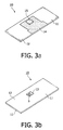
- Fig. 3a shows, in top view, a component of the device 1 comprising the sensor surface 4 on the first side 11 on which a sensor 15 is attached, i.e. a sensor supporting element 10.
- the sensor supporting element 10 thus has a first side 11, whereon e.g. tracks may be presents and a second side 12.
- Fig. 3b shows, in top view, the second side 12 of a sensor supporting element 10.
- An opening is shown for providing connection between the second side 12 of the sensor supporting element and the sensor surface 5.
- the opening is shown having sloped walls 13.
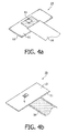
- Fig. 4a and Fig. 4b show, in top view, the sensor supporting element 10 after the provision of a connection means 16 for external contacting, e.g. a flex foil 16 for external contacting.
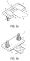
- Fig. 5a and Fig. 5b show the device 1 after assembly of lid 8 and the sensor supporting element 10, in top view, from the first side 11 of the supporting element 10 respectively from the second side 17 of the lid 8.
- an adhesive is made , for example, of an adhesive.
- the present invention relates to a process for manufacturing a device 1 for detecting the presence of an analyte in a sample fluid 20.
- the device may be a device as described in the first aspect of the present invention, comprising the same features and advantages.
- the process comprises applying a reagent 4 on a carrier surface 3.
- the reagent 4 may be deposited in any suitable way, such as but not limited to e.g. micro-deposition techniques.
- deposition is dosing, whereby valves are used to control application of small volumes on the carrier surface.
- Other techniques may comprise non-contact printing techniques such as inkjet printing or jetting, or contact printing such as tampon printing, micro contact printing, screen printing, stamp printing, etc.
- the reagent 4 may for instance be deposited as one or more layers.
- the reagent 4 may be dried on the carrier surface 3. Drying of the reagent on the carrier surface 3 may be performed by application of a low ambient vapour pressure, although the latter is not obligatory. Drying may comprise both drying a reagent 4 from its fluid phase as well as drying a reagent 4 from its solid phase. It may comprise reducing the amount of aqueous components present in the reagent 4. Heat may be used during drying to improve its efficiency. For instance, the carrier surface 3 may be heated. A good drying improves shelf life, i.e. storage properties. In an exemplary embodiment, the ambient provided during depositing and/or drying of the reagent 4 has a very low humidity. The latter has the advantage that the drying proceeds rapidly.
- an inert gas can be used in the ambient. With very low humidity there is meant a relative humidity less than 30%, more preferably a relative humidity less than 10% and even more preferably a relative humidity of less than 3%.
- the reagent 4 may be in a lyophilised form, i.e. has been freeze-dried by first freezing it and afterwards subliming the frozen water formed therein. In other words, a step of lyophilizing also may be applied.
- the process of this second aspect further comprises providing a sensor surface 5 distinct from the carrier surface 3.
- the sensor surface 5 may be obtained pre-made whereon biologically or biochemical active moieties are already provided, or it may be obtained via the coating of a sensor or sensor surface with biologically or biochemical active moieties.
- the process of this second aspect further comprises forming a detection region delimited by the carrier surface 3 and the sensor surface 5, e.g. forming a detection chamber comprising the carrier surface 3 and the sensor surface 5.
- Such an assembly of a detection chamber may be performed by positioning the different components in their appropriate position and fixing the components to each other. The latter may be performed in any suitable way, e.g. by glueing, clipping, clicking, welding etc. Further assembly of the device for detecting also may be performed, i.e.
- the assembly i.e. forming the detection region, may be performed after the reagent has been applied to the carrier surface or it may be performed prior to applying the reagent on the carrier surface.
- the reagent may be introduced via openings performed in the device.
- An advantage of separate manufacturing the sensor surface and the reagent applied to the carrier surface and thereafter assembling is that independent optimization of the preparation may be performed and thus less unwanted cross-interaction between both components occurs.
- the process of this second aspect of the present invention further comprises providing an inlet and/or an outlet for sample fluid at a location distinct, i.e. remote from the carrier surface.
- Those inlet and or outlet can be formed by any way known to the person skilled in the art such as drilling, boring, punching, cutting, inserting an object, e.g. an hollow tube, and the likes.
- the distance between the carrier surface and the sensor surface may be tuned during manufacturing. This distance should be such as to provide enough time for a proper dissolution of the reagent by the sample fluid and for a proper homogenisation of the resulting fluid mixture and to provide for rapid detection. A compromise must therefore be found.
- the process of this second embodiment further comprises providing magnetic actuation means below and/or above the sensor surface.
- actuation means may be embedded in a component, or may be positioned as separate component. It may be performed as part of the assembly of the detection chamber or it may be provided after assembly of the detection chamber.
- the present invention relates to a method for detecting the presence of an analyte in a sample fluid 20.
- the method preferably may be performed using a device 1 for detecting as described in the first aspect, although the invention is not limited thereto.
- the method for detecting comprises contacting the sample fluid 20 with a reagent 4 present on a carrier surface 3 thereby forming a fluid mixture, the carrier surface delimiting a detection region 2.
- analytes present in the sample fluid 20 may interact with the reagent 4, thus assisting in the detectability of the particles of interest.
- This contacting step may comprise dissolving a dissolvable matrix wherein reagent components are positioned, e.g. dissolving a reagent layer applied to a carrier surface 3.
- the method thus furthermore comprises contacting the fluid mixture with a sensor surface, the sensor surface 5 being distinct from the carrier surface 3 and delimiting the detection region 2. In this way interaction between the particles of interest and the sensor surface 5 is obtained. Such an interaction can be performed rapidly as the sensor surface 5 is initially substantially free of reagent 4, thus resulting in free areas of interaction for the particles of interest.
- the detection region 2 may be a detection chamber 2 comprising the carrier surface 3 and the sensor surface 5.
- the method furthermore comprises detecting the interaction between the fluid mixture and the sensor surface.
- the latter allows to obtain a quantitative or qualitative analysis of the sample fluid, e.g. to obtain information about the presence and quantity of certain components in the sample fluid.
- the detection of the interaction of the fluid mixture the sensor surface may comprise the detection of the analyte via detection of the probes.
- the probes (e.g. the labeled antibodies) and the sensor are both exposed to the analyte and the analyte influences the binding of the probes to the sensor surface.
- an analyte labeled with e.g. a magnetic or magnetisable particle either bind to immobilised capture probes (sandwich assay), or compete with analyte analogues to bind to capture probes (competitive assay).
- the amount of bound labeled probes e.g. labeled with magnetic particles
- binding assays may involve adherence of magnetically labeled molecules to the sensor in numbers that reflect the concentration or presence of the analyte molecule. Such tests may e.g.
- Detection of a magnetic or magnetisable particle when used as a label is generally done by application of an electric, or magnetic, or electromagnetic field and using a magnetic or nonmagnetic, e.g. optical or acoustic sensor. Examples of embodiments for the detection of a magnetic or magnetisable particle are given in patent application WO2005/116661 and in references cited therein. Acoustic and/or sonic detection of labels may also be used. In some embodiments, the magnetic particles are only presents in the lyophilised beads to enable their manipulation via magnetic means, i.e.
- the detection of the probes on or in the sensor will be adapted to the type of label linked to the probes.
- the various types of binding and releasing assays may use magnetic particles that comprise optical properties such as e.g. fluorescent, chromogenic, scattering, absorbing, refracting, reflecting, SERRS-active or (bio)chemiluminescent labels, molecular beacons, radioactive labels, or enzymatic labels.
- Optically active labels may emit light detectable by a detector, e.g. in the visual, infrared or ultraviolet wavelength region. Nevertheless, the invention is not limited thereto and optical labels, in the present application, may refer to labels emitting in any suitable and detectable wavelength region of the electromagnetic spectrum.
- contacting the carrier surface with the sample fluid may be obtained by dipping the assembly of carrier surface and detection surface in the sample fluid.
- the time required to perform an analysis from the sample fluid injection to the detection of the analyte may be tuned. For instance, this time can be selected or tuned by varying the height of the detection region, e.g. detection chamber. Preferably, the height of the chamber can be selected or tuned between 30 ⁇ m-500 ⁇ m. This can be performed during manufacturing or after manufacturing.
- displacement means such as for example mechanical, electromechanical or electromagnetic displacement means, may be provided to control the distance between the carrier surface and the sensor, thus allowing to tune the distance between the carrier surface and the sensor.
- Such tunable parts may e.g.
- MEMS micro-electro-mechanical systems
- the time required to perform an analysis i.e. the mixing time of the reagent and the sample fluid and the time between the mixing and detection, also may be tuned by actuating components of the reagent once they have mixed with the sample fluid.
- the actuating may comprise mixing components of the reagent in the sample fluid or displacing components or bound components towards the sensor surface.
- Such actuating may be actuating using magnetic force, using electric force, using mechanical or acoustical force, etc. If for example magnetic particles or beads are used to label probes present in the reagent magnetic actuation may be used.
- a step of magnetically actuating the magnetic or magnetisable particles may thus be performed in order to direct the magnetic or magnetisable particles toward the sensor surface.
- a step of magnetically actuating the magnetic or magnetisable particles may be performed in order to mix the probes with the sample fluid.
- a step of magnetically retaining the magnetic or magnetisable particles may be performed in order to control the time of their release.
- the magnetic properties of the magnetic beads or particles and the strength of the magnetic field used may be used to influence on the pre-incubation time. Magnetic forces can for example be tuned by tuning the strengths of the permanent magnets or their distance to the measurement chamber, or in case of electro-magnets they can be tuned by tuning the current through the coils. Appropriate strength for the magnetic field are in the range 0.05 T and above, preferably between 0.05 and 1 Tesla.
- the size of the magnetic beads is another parameter that influence this time. Preferred sizes for magnetic beads or particles range between 200 nm and 1 ⁇ m.
- the method thus comprises magnetically actuating the magnetic or magnetisable particles prior to detecting.
- the magnetically actuating may e.g. be performed using a magnetic actuation means below the sensor surface.
- the use of magnetic actuation means below the sensor surface enables to direct the magnetic labels toward the sensor surface at relatively high speed.
- the presence of magnetic actuation means both below and above the sensor surface enables, if at least one of those actuation means is switchable, to improve the contacting of the magnetically labeled probes with the analyte, i.e. the mixing, by either alternatively switching the magnetic actuation means situated above and under the sensor surface or intermittently switching or decreasing/increasing the power of magnetic actuation means situated above or under the sensor surface.
- H the magnetic field strength
- ⁇ the magnetic susceptibility ( ⁇ 2.5 for super-paramagnetic beads)
- M the overall magnetisation on the label.
- the friction force on a bead is given by equation 2:
- the pre-incubation time can be tuned by changing the height of the chamber, the size of the beads and the strength of the magnetic field.
- Magnetic particles 500 nm COOH Masterbeads (Ademtech) coated with anti-opi antibodies, stored in storage buffer (Ademtech) were wished three times and were resuspended in a drying buffer (10mg/ml BSA, 10% sucrose, 0.1% tritonx405, 10mM Tris HCl pH 7.1) using a magnetic washing step known to the person skilled in the art.
- the final magnetic bead concentration was adapted to 1 wt%.
- a small droplet of this reagent 4 was placed on a carrier surface 3 comprised in the channel 18 of a lid 8 as described on Fig. 2a .
- the reagent was dried in air for 1 h and stored in a sealed box with silica pouches.
- the lid 8 was assembled to a sensor supporting element 10 as described in Fig. 4a and 4b to form a device 1 as described in Fig. 5a and 5b .
- the sensor was of a magnetic type, i.e. a giant magnetic resistance sensor (GMR sensor).
- the sensor surface was coated with a 1 g/ml solution of BSA-OPI (the OPI-analogue) in coating buffer (10mM sodium borate, 50mM NaCl, 0.05% Tween20, pH 9.0).
- BSA-morphine is the OPI-analogue.
- a coil suitable for magnetic actuation was provided under and above the device.
- the device 1 was connected to a reader via a flex foil 16, and the magnetic attraction was started by turning on the coil below the device 1.
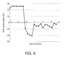
- Fig. 6 shows the GMR signal as a function of time. The initial value is roughly 25 ⁇ V.
- a sample fluid composed of a buffer (0.08M sodium/potassium phosphate, pH 8.1-8.2 containing 0.4M sodium chloride, 0.05%(w/v) sodium azide and 0.1%(w/v) Triton-X405) (not containing antigens) was injected in the device via an inlet 6 and the reagent was allowed to disperse under magnetic actuation.
- the magnetic beads, bearing anti-OPI antibodies, now in free suspension in the sample fluid were attracted for 65 seconds toward the sensor surface 5.
- the GMR signal dropped, indicating the sensing of the magnetic beads by the sensor.
- the top coil was turned on and the bottom coil turned off and the unbound and aspecifically bound magnetic beads were repelled from the surface. All unbound beads were removed from the sensor surface and gathered at the top of the chamber, in the vicinity of the carrier surface.
- the signal representing the binding of the magnetic labels is given by the reduction in GMR signal.
- the GMR signal reduction is 30.2 V.
- Figure 6 shows the GMR sensor signal as a function of time.
- a reagent 4 applied on a carrier surface 3, in the present example being the roof of the detection chamber 2, i.e. a surface facing the sensor surface 5 and delimiting one side of the detection chamber 2 distinct from the sensor surface 5 can efficiently be liberated and mixed with a sample fluid, and the magnetic labels can be bound to the surface.
- a dose-response curve was measured for a competitive Morphine assay using magnetic particles dried in a fluidics device according to an embodiment of the present invention.
- the sensor was prepared as follows :
- the bottom part e.g. as illustrated by bottom part 5 of the fluidics device, was coated with BSA-Morphine according to the following procedure : The bottom part was first cleaned by providing it in a nitrogen flow. A 10 ⁇ g/ml BSA-morphine solution was then prepared by mixing 196 ⁇ l of coating buffer with 4 ⁇ l of BSA-morphine (100 ⁇ g/ml).
- the coating buffer thereby was made by mixing 15 mM Sodiumcarbonate having a density 1,59 g/l and a molecular weight of 106 g/mol with 35mM Sodiumbicarbonate having a density of 3,94 g/l and a molecular weight of 84 g/mol and with 0.05% Na-azide having a density of 0,5 g/l, adjusting its pH to 9.6 and storing it at 4°C.
- a droplet of 2 ⁇ l of BSA-morphine solution was applied to the bottom part of the fluidics device, this was incubated in a moist environment O/N at room temperature and thereafter the part was rinsed with cleaning liquid, in the present example being milliQ.
- the part was further soaked for 30 minutes in a solution of 1 x PBS (Phosphate Buffered Saline) and 0.05% Tween20, dried in a nitrogen flow and stored in a sealed box near a water absorbing material such as silica bags.
- 1 x PBS Phosphate Buffered Saline
- Tween20 0.05% Tween20
- the top and bottom part of the biosensor was assembled by using tape, and the sensors were kept onder dry conditions at room temperature. After 24 hrs the redispersion quality and antibody activity was tested by doing a competitive assay in the optical biosensor system.
- the assay comprised addition of buffer spiked with Morphine in the fluidic device by autonomous filling through a capillary channel, redispersion of the beads and subsequent attracting the magnetic beads to the sensor surface (with an actuation means, such as e.g. a bottom magnet).
- the buffer added was a 2x concentrated AJ buffer with Na 2 HPO 4 10,76 g/l, KH 2 PO 4 0.577 g/l, NaCl 23,38 g/l and 0,01% Na-azide which was stored at RT and to which, before use, 0.1% Triton X-405 was added combined with a controlled amount of morphine.
- a 2x concentrated AJ buffer with Na 2 HPO 4 10,76 g/l, KH 2 PO 4 0.577 g/l, NaCl 23,38 g/l and 0,01% Na-azide which was stored at RT and to which, before use, 0.1% Triton X-405 was added combined with a controlled amount of morphine.
- the response to different morphine concentrations was tested by adding different morphine concentrations, i.e.
- the dose response curve for the above described assays are shown in Fig. 7 for the different morphine concentrations.
- the datapoints for morphine concentrations of 5 ng/ ⁇ l or lower were measured in five-fold, whereas the remaining two datapoints for higher morphine concentrations were measured in duplicate.
- the graph illustrates the response of the sensor on morphine by indicating the signal change in percentage as function of the amount of morphine added.
- the above example illustrates one of the large number of possible detection applications for which the sensor can be used.
Landscapes
- Health & Medical Sciences (AREA)
- Immunology (AREA)
- Life Sciences & Earth Sciences (AREA)
- Chemical & Material Sciences (AREA)
- Engineering & Computer Science (AREA)
- Pathology (AREA)
- Biomedical Technology (AREA)
- Hematology (AREA)
- General Physics & Mathematics (AREA)
- Molecular Biology (AREA)
- Urology & Nephrology (AREA)
- Analytical Chemistry (AREA)
- General Health & Medical Sciences (AREA)
- Biochemistry (AREA)
- Physics & Mathematics (AREA)
- Cell Biology (AREA)
- Medicinal Chemistry (AREA)
- Food Science & Technology (AREA)
- Microbiology (AREA)
- Biotechnology (AREA)
- Chemical Kinetics & Catalysis (AREA)
- Electrochemistry (AREA)
- Apparatus Associated With Microorganisms And Enzymes (AREA)
- Measuring Or Testing Involving Enzymes Or Micro-Organisms (AREA)
- Investigating Or Analysing Biological Materials (AREA)
Claims (13)
- Biosensoreinrichtung (1) zum Detektieren des Vorhandenseins eines Analyten in einer Probenflüssigkeit, wobei die Einrichtung umfasst:- einen Detektionsbereich (2), wobei der Detektionsbereich begrenzt ist durch(a) eine Trägeroberfläche (3), die für die Probenflüssigkeit aus dem Inneren des Detektionsbereichs (2) erreichbar ist, wobei die Trägeroberfläche (3) ein Reagenz (4) umfasst, und(b) eine Sensoroberfläche (5), die für die Probenflüssigkeit aus dem Inneren des Detektionsbereichs (2) erreichbar ist, wobei die Sensoroberfläche (5) von der Trägeroberfläche (3) getrennt ist, sowie- einen Einlass für die Probenflüssigkeit (6), wobei der Einlass für die Probenflüssigkeit (6) eine von dem Reagenz auf der Trägeroberfläche entfernte Einlassöffnung in dem Detektionsbereich (2) aufweist,wobei sich das Reagenz in einer löslichen Matrix befindet, in der Reagenzkomponenten positioniert sind, wobei der Einlass für die Probenflüssigkeit (6) eine Kapillare umfasst und die Probenflüssigkeit eine wässrige Zusammensetzung ist.
- Einrichtung (1) nach Anspruch 1, wobei das Reagenz in einer lyophilisierten Form vorliegt.
- Einrichtung (1) nach Anspruch 2, wobei das Reagenz eine poröse Schicht bildet.
- Einrichtung (1) nach Anspruch 2, wobei das Reagenz (4) in einer oder mehreren lyophilisierten Kugeln enthalten ist.
- Einrichtung (1) nach einem der vorangegangenen Ansprüche, wobei die Einrichtung weiterhin eine Pumpe oder Spritze umfasst, um die Probenflüssigkeit durch den Einlass für die Probenflüssigkeit (6) zu drücken.
- Einrichtung (1) nach einem der vorangegangenen Ansprüche, wobei die Einrichtung einen Abstand zwischen der Trägeroberfläche (3) und der Sensoroberfläche (5) aufweist, wobei die Trägeroberfläche (3) nicht koplanar mit der Sensoroberfläche ist, und wobei der Abstand zwischen 30 µm und 500 µm beträgt.
- Einrichtung (1) nach Anspruch 6, wobei der Abstand einstellbar ist.
- Einrichtung (1) nach einem der Ansprüche 1 bis 7, wobei der Detektionsbereich (2) eine Detektionskammer (2) ist, die durch Wände begrenzt ist.
- Einrichtung (1) nach Anspruch 8, wobei die Detektionskammer (2) ein Volumen von 0,1 µl bis 1 µl aufweist.
- Einrichtung (1) nach einem der Ansprüche 1 bis 9, wobei die Einrichtung Retentionsmittel (28) umfasst, um das Reagenz (4) oder Komponenten desselben auf der Trägeroberfläche zurückzuhalten.
- Einrichtung (1) nach einem der Ansprüche 1 bis 10, wobei die Trägeroberfläche nicht-porös ist.
- Verfahren zur Herstellung einer Biosensoreinrichtung (1) zum Detektieren des Vorhandenseins eines Analyten in einer Probenflüssigkeit, wobei das Verfahren die folgenden Schritte umfasst, wonach:- eine Trägeroberfläche (3) vorgesehen wird,- auf der Trägeroberfläche (3) ein Reagenz (4) verwendet wird, wobei sich das Reagenz in einer löslichen Matrix befindet, in der Reagenzkomponenten positioniert sind,- eine Sensoroberfläche (3) vorgesehen wird, die von der Trägeroberfläche (3) getrennt ist,- ein Detektionsbereich (2) gebildet wird, der durch die Trägeroberfläche (3) und die Sensoroberfläche (5) begrenzt ist, und- an einer von dem Reagenz auf der Trägeroberfläche (3) entfernten Stelle ein Einlass für die Probenflüssigkeit (6) gebildet wird,wobei der Einlass für die Probenflüssigkeit (6) eine Kapillare umfasst und die Probenflüssigkeit eine wässrige Zusammensetzung ist.
- Verfahren zum Detektieren des Vorhandenseins eines Analyten in einer Probenflüssigkeit, wobei das Verfahren die folgenden Schritte umfasst, wonach:- die Probenflüssigkeit in eine Biosensoreinrichtung eingeführt wird, wobei die Einrichtung umfasst:- einen Detektionsbereich (2), wobei der Detektionsbereich begrenzt ist durch(a) eine Trägeroberfläche (3), die für die Probenflüssigkeit aus dem Inneren des Detektionsbereichs (2) erreichbar ist, wobei die Trägeroberfläche (3) ein Reagenz (4) umfasst, das sich in einer löslichen Matrix befindet, in der Reagenzkomponenten positioniert sind, und(b) eine Sensoroberfläche (5), die für die Probenflüssigkeit aus dem Inneren des Detektionsbereichs (2) erreichbar ist, wobei die Sensoroberfläche (5) von der Trägeroberfläche (3) getrennt ist, sowie- einen Einlass für die Probenflüssigkeit (6), wobei der Einlass für die Probenflüssigkeit (6) von dem Reagenz auf der Trägeroberfläche (3) entfernt ist,- wobei die Probenflüssigkeit über den Einlass für die Probenflüssigkeit (6) in die Einrichtung (1) eingeführt wird,- die Probenflüssigkeit mit einem auf der Trägeroberfläche (3) vorhandenen Reagenz (4) in Kontakt gebracht und dadurch ein Flüssigkeitsgemisch erzeugt wird, wobei die Trägeroberfläche (3) für die Probenflüssigkeit aus dem Inneren eines Detektionsbereichs (2) erreichbar ist,- das Flüssigkeitsgemisch mit einer Sensoroberfläche (5) in Kontakt gebracht wird, wobei die Sensoroberfläche (5) von der den Detektionsbereich (2) begrenzenden Trägeroberfläche (3) getrennt ist, und- eine Interaktion zwischen dem Flüssigkeitsgemisch und der Sensoroberfläche (5) detektiert wird,wobei der Einlass für die Probenflüssigkeit (6) eine Kapillare umfasst und die Probenflüssigkeit eine wässrige Zusammensetzung ist.
Priority Applications (1)
| Application Number | Priority Date | Filing Date | Title |
|---|---|---|---|
| EP08789360A EP2181333B1 (de) | 2007-07-20 | 2008-07-18 | Erkennungsverfahren und -systeme |
Applications Claiming Priority (3)
| Application Number | Priority Date | Filing Date | Title |
|---|---|---|---|
| EP07112829A EP2017618A1 (de) | 2007-07-20 | 2007-07-20 | Detektionsverfahren und -systeme |
| EP08789360A EP2181333B1 (de) | 2007-07-20 | 2008-07-18 | Erkennungsverfahren und -systeme |
| PCT/IB2008/052897 WO2009013683A1 (en) | 2007-07-20 | 2008-07-18 | Methods and systems for detecting |
Publications (2)
| Publication Number | Publication Date |
|---|---|
| EP2181333A1 EP2181333A1 (de) | 2010-05-05 |
| EP2181333B1 true EP2181333B1 (de) | 2012-05-23 |
Family
ID=38893331
Family Applications (2)
| Application Number | Title | Priority Date | Filing Date |
|---|---|---|---|
| EP07112829A Ceased EP2017618A1 (de) | 2007-07-20 | 2007-07-20 | Detektionsverfahren und -systeme |
| EP08789360A Active EP2181333B1 (de) | 2007-07-20 | 2008-07-18 | Erkennungsverfahren und -systeme |
Family Applications Before (1)
| Application Number | Title | Priority Date | Filing Date |
|---|---|---|---|
| EP07112829A Ceased EP2017618A1 (de) | 2007-07-20 | 2007-07-20 | Detektionsverfahren und -systeme |
Country Status (7)
| Country | Link |
|---|---|
| US (1) | US9778254B2 (de) |
| EP (2) | EP2017618A1 (de) |
| JP (1) | JP5710252B2 (de) |
| CN (1) | CN101755209B (de) |
| BR (1) | BRPI0814087A2 (de) |
| RU (1) | RU2480768C2 (de) |
| WO (1) | WO2009013683A1 (de) |
Cited By (1)
| Publication number | Priority date | Publication date | Assignee | Title |
|---|---|---|---|---|
| US10493445B2 (en) | 2013-04-30 | 2019-12-03 | Koninklijke Philips N.V. | Fluidic system for processing a sample fluid |
Families Citing this family (30)
| Publication number | Priority date | Publication date | Assignee | Title |
|---|---|---|---|---|
| WO2009115951A1 (en) * | 2008-03-17 | 2009-09-24 | Koninklijke Philips Electronics N.V. | Cartridge for assays with magnetic particles |
| CN102017814A (zh) * | 2008-04-29 | 2011-04-13 | 皇家飞利浦电子股份有限公司 | 电子纺织物 |
| US9086396B2 (en) * | 2008-11-28 | 2015-07-21 | Roche Molecular Systems, Inc. | System and method for the automated processing of fluids, method for determining the matching of objects |
| WO2010086772A1 (en) * | 2009-01-29 | 2010-08-05 | Koninklijke Philips Electronics N.V. | System and method for assay |
| US10196700B2 (en) | 2009-03-24 | 2019-02-05 | University Of Chicago | Multivolume devices, kits and related methods for quantification and detection of nucleic acids and other analytes |
| CA2756463C (en) | 2009-03-24 | 2019-01-22 | University Of Chicago | Slip chip device and methods |
| US9447461B2 (en) | 2009-03-24 | 2016-09-20 | California Institute Of Technology | Analysis devices, kits, and related methods for digital quantification of nucleic acids and other analytes |
| US9464319B2 (en) | 2009-03-24 | 2016-10-11 | California Institute Of Technology | Multivolume devices, kits and related methods for quantification of nucleic acids and other analytes |
| ES2549609T3 (es) | 2009-11-16 | 2015-10-29 | Silicon Biodevices, Inc. | Dispositivo de filtración para ensayos |
| US20140347952A1 (en) * | 2012-12-19 | 2014-11-27 | Dxna Llc | Mixing apparatus and methods |
| CN103890588B (zh) | 2011-10-20 | 2017-02-15 | 皇家飞利浦有限公司 | 具有培养期的磁性粒子检测 |
| DE102011118742A1 (de) * | 2011-11-17 | 2013-05-23 | Forschungszentrum Jülich GmbH | Detektor für magnetische Partikel in einer Flüssigkeit |
| US9052315B2 (en) | 2012-05-09 | 2015-06-09 | Advanced Animal Diagnostics, Inc. | Rapid detection of analytes in liquid samples |
| DE102012105379B3 (de) * | 2012-06-21 | 2013-07-25 | Bernd Donner | Sensor und Verfahren zur Messung von Partikeln in Medien |
| US10359614B2 (en) | 2012-07-03 | 2019-07-23 | Advanced Animal Diagnostics, Inc. | Diagnostic apparatus |
| DE102012211626A1 (de) * | 2012-07-04 | 2014-01-09 | Siemens Aktiengesellschaft | Anordnung zur Quantifizierung von Zellen einer Zellsuspension |
| US9752968B2 (en) | 2012-12-21 | 2017-09-05 | Luminex Corporation | Rotating shielded magnetic actuator |
| US9636689B2 (en) | 2012-12-21 | 2017-05-02 | Luminex Corporation | Rotating magnetic actuator |
| US9797893B2 (en) | 2013-05-09 | 2017-10-24 | Advanced Animal Diagnostics, Inc. | Rapid detection of analytes in liquid samples |
| US10155244B2 (en) * | 2013-09-16 | 2018-12-18 | Taiwan Semiconductor Manufacturing Co., Ltd. | Fluid deposition appartus and method |
| US20160258945A1 (en) * | 2013-10-21 | 2016-09-08 | Northeastern University | Point-of-care immunosensing device for multi-biomarker detection |
| JP6635897B2 (ja) * | 2016-08-30 | 2020-01-29 | シスメックス株式会社 | 試料分析用カートリッジ及びその製造方法、並びにその利用 |
| WO2018119173A1 (en) * | 2016-12-22 | 2018-06-28 | Fundamental Solutions Corporation | Universal biosensor system for analyte detection |
| WO2019055007A1 (en) | 2017-09-14 | 2019-03-21 | Hewlett-Packard Development Company, L.P. | MICROFLUIDIC HOUSING |
| US11141726B2 (en) * | 2017-11-13 | 2021-10-12 | Lifeos Genomics Corporation | Cartridge and method of distributing biological sample in fluid channel thereof |
| KR102019818B1 (ko) * | 2018-02-26 | 2019-09-09 | 주식회사 어큐노스 | 반응 잠복 시간 조절형 생화학 검출 장치 및 이의 제조 방법 |
| EP3628071B1 (de) * | 2018-07-27 | 2022-07-06 | Zepto Life Technology, LLC | System und verfahren zur probenvorbereitung bei der gmr-basierten detektion von biomarkern |
| EP3666163B1 (de) * | 2018-12-10 | 2023-02-01 | Max-Planck-Gesellschaft zur Förderung der Wissenschaften e.V. | Verfahren zur gleichzeitigen kalibrierung für ein magnetisches lokalisierungs- und betätigungssystem |
| CN112945869B (zh) * | 2021-02-01 | 2021-11-16 | 杭州赛基生物科技有限公司 | 智慧医院液体试样检测试剂盒用膜载体、试剂盒及膜载体制造方法 |
| IL311308A (en) * | 2024-03-06 | 2025-10-01 | M S Tech Ltd | Substance sampling setups and methods |
Family Cites Families (23)
| Publication number | Priority date | Publication date | Assignee | Title |
|---|---|---|---|---|
| US5110727A (en) * | 1987-04-03 | 1992-05-05 | Cardiovascular Diagnostics, Inc. | Method for performing coagulation assays accurately, rapidly and simply, using dry chemical reagents and paramagnetic particles |
| WO1994019690A1 (en) * | 1993-02-17 | 1994-09-01 | Cardiovascular Diagnostics, Inc. | Dry chemistry cascade immunoassay and affinity assay |
| US6074827A (en) * | 1996-07-30 | 2000-06-13 | Aclara Biosciences, Inc. | Microfluidic method for nucleic acid purification and processing |
| US5922537A (en) * | 1996-11-08 | 1999-07-13 | N.o slashed.AB Immunoassay, Inc. | Nanoparticles biosensor |
| JP2001159618A (ja) * | 1999-12-03 | 2001-06-12 | Matsushita Electric Ind Co Ltd | バイオセンサ |
| US6716620B2 (en) * | 2000-04-17 | 2004-04-06 | Purdue Research Foundation | Biosensor and related method |
| RU2278612C2 (ru) * | 2000-07-14 | 2006-06-27 | Лайфскен, Инк. | Иммуносенсор |
| US6736978B1 (en) * | 2000-12-13 | 2004-05-18 | Iowa State University Research Foundation, Inc. | Method and apparatus for magnetoresistive monitoring of analytes in flow streams |
| CA2468674A1 (en) * | 2001-12-05 | 2003-06-12 | University Of Washington | Microfluidic device and surface decoration process for solid phase affinity binding assays |
| JP2003185566A (ja) * | 2001-12-13 | 2003-07-03 | Matsushita Electric Ind Co Ltd | 分析用光学ディスク及びその測定器 |
| TWI306153B (en) * | 2002-01-29 | 2009-02-11 | Asahi Chemical Ind | Biosensor, magnetic molecule measurement method, and measurement object measuring method |
| US20060134713A1 (en) | 2002-03-21 | 2006-06-22 | Lifescan, Inc. | Biosensor apparatus and methods of use |
| US20040018611A1 (en) * | 2002-07-23 | 2004-01-29 | Ward Michael Dennis | Microfluidic devices for high gradient magnetic separation |
| JP4399211B2 (ja) * | 2002-12-21 | 2010-01-13 | 株式会社ハイニックスセミコンダクター | バイオセンサー |
| US7906345B2 (en) | 2003-11-12 | 2011-03-15 | The Board Of Trustees Of The Leland Stanford Junior University | Magnetic nanoparticles, magnetic detector arrays, and methods for their use in detecting biological molecules |
| CN1934444A (zh) * | 2004-03-05 | 2007-03-21 | 艾格麦迪卡瑞士股份有限公司 | 用于确定生理液体中的分析物浓度的分析物测试系统 |
| WO2005116661A1 (en) | 2004-05-24 | 2005-12-08 | Koninklijke Philips Electronics N.V. | Magneto-resistive sensor for high sensitivity depth probing |
| US20090054255A1 (en) * | 2004-07-01 | 2009-02-26 | The Regents Of The University Of California | Microfluidic devices and methods |
| JP2006098129A (ja) * | 2004-09-28 | 2006-04-13 | Aisin Seiki Co Ltd | マイクロチャネルチップシステム及び検出チップ |
| JP4680587B2 (ja) | 2004-12-28 | 2011-05-11 | 旭化成株式会社 | バイオセンサ、対象物測定方法、バイオセンサ用カートリッジ及び不織布 |
| CN101198870A (zh) * | 2005-06-17 | 2008-06-11 | 皇家飞利浦电子股份有限公司 | 精密磁性生物传感器 |
| JP5221549B2 (ja) * | 2006-10-12 | 2013-06-26 | コーニンクレッカ フィリップス エレクトロニクス エヌ ヴィ | 試薬層を有した高速バイオセンサ |
| EP2017006A1 (de) * | 2007-07-20 | 2009-01-21 | Koninklijke Philips Electronics N.V. | Mikrofluidische Verfahren und Systeme zur Verwendung bei der Analytdetektion |
-
2007
- 2007-07-20 EP EP07112829A patent/EP2017618A1/de not_active Ceased
-
2008
- 2008-07-18 CN CN2008800251464A patent/CN101755209B/zh active Active
- 2008-07-18 US US12/669,217 patent/US9778254B2/en active Active
- 2008-07-18 RU RU2010106085/15A patent/RU2480768C2/ru not_active IP Right Cessation
- 2008-07-18 JP JP2010516639A patent/JP5710252B2/ja active Active
- 2008-07-18 BR BRPI0814087-1A2A patent/BRPI0814087A2/pt not_active IP Right Cessation
- 2008-07-18 EP EP08789360A patent/EP2181333B1/de active Active
- 2008-07-18 WO PCT/IB2008/052897 patent/WO2009013683A1/en not_active Ceased
Cited By (1)
| Publication number | Priority date | Publication date | Assignee | Title |
|---|---|---|---|---|
| US10493445B2 (en) | 2013-04-30 | 2019-12-03 | Koninklijke Philips N.V. | Fluidic system for processing a sample fluid |
Also Published As
| Publication number | Publication date |
|---|---|
| RU2480768C2 (ru) | 2013-04-27 |
| RU2010106085A (ru) | 2011-08-27 |
| EP2181333A1 (de) | 2010-05-05 |
| CN101755209A (zh) | 2010-06-23 |
| US9778254B2 (en) | 2017-10-03 |
| US20100297780A1 (en) | 2010-11-25 |
| BRPI0814087A2 (pt) | 2015-02-03 |
| JP2010534321A (ja) | 2010-11-04 |
| JP5710252B2 (ja) | 2015-04-30 |
| WO2009013683A1 (en) | 2009-01-29 |
| CN101755209B (zh) | 2013-05-08 |
| EP2017618A1 (de) | 2009-01-21 |
Similar Documents
| Publication | Publication Date | Title |
|---|---|---|
| EP2181333B1 (de) | Erkennungsverfahren und -systeme | |
| EP2170515B1 (de) | Mikrofluidische verfahren und systeme zur verwendung bei der analytdetektion | |
| RU2482495C2 (ru) | Быстрый биосенсор со слоем реагента | |
| CN110988331B (zh) | 一种基于磁珠技术和试剂冻干技术的微流控芯片检测方法和微流控芯片 | |
| EP2283361B1 (de) | Vorrichtung und verfahren zur feststellung von analyten in der spucke | |
| EP2078199B1 (de) | Nachweissystem und verfahren mit hilfe eines magnetischen und/oder elektrischen etiketts | |
| US20130156643A1 (en) | Device and method for manipulating or analysing a liquid sample | |
| EP1970705A1 (de) | Analytnachweis anhand von Kügelchen | |
| WO2010086772A1 (en) | System and method for assay | |
| WO2007072444A2 (en) | Biosensor device | |
| Ligler et al. | Biological microstructures in biosensors |
Legal Events
| Date | Code | Title | Description |
|---|---|---|---|
| PUAI | Public reference made under article 153(3) epc to a published international application that has entered the european phase |
Free format text: ORIGINAL CODE: 0009012 |
|
| 17P | Request for examination filed |
Effective date: 20100222 |
|
| AK | Designated contracting states |
Kind code of ref document: A1 Designated state(s): AT BE BG CH CY CZ DE DK EE ES FI FR GB GR HR HU IE IS IT LI LT LU LV MC MT NL NO PL PT RO SE SI SK TR |
|
| AX | Request for extension of the european patent |
Extension state: AL BA MK RS |
|
| 17Q | First examination report despatched |
Effective date: 20100622 |
|
| DAX | Request for extension of the european patent (deleted) | ||
| GRAP | Despatch of communication of intention to grant a patent |
Free format text: ORIGINAL CODE: EPIDOSNIGR1 |
|
| RIC1 | Information provided on ipc code assigned before grant |
Ipc: G01N 33/543 20060101AFI20111026BHEP Ipc: G01N 27/74 20060101ALI20111026BHEP |
|
| GRAS | Grant fee paid |
Free format text: ORIGINAL CODE: EPIDOSNIGR3 |
|
| GRAA | (expected) grant |
Free format text: ORIGINAL CODE: 0009210 |
|
| AK | Designated contracting states |
Kind code of ref document: B1 Designated state(s): AT BE BG CH CY CZ DE DK EE ES FI FR GB GR HR HU IE IS IT LI LT LU LV MC MT NL NO PL PT RO SE SI SK TR |
|
| REG | Reference to a national code |
Ref country code: GB Ref legal event code: FG4D |
|
| REG | Reference to a national code |
Ref country code: CH Ref legal event code: EP |
|
| REG | Reference to a national code |
Ref country code: AT Ref legal event code: REF Ref document number: 559307 Country of ref document: AT Kind code of ref document: T Effective date: 20120615 |
|
| REG | Reference to a national code |
Ref country code: IE Ref legal event code: FG4D |
|
| REG | Reference to a national code |
Ref country code: DE Ref legal event code: R096 Ref document number: 602008015900 Country of ref document: DE Effective date: 20120726 |
|
| REG | Reference to a national code |
Ref country code: NL Ref legal event code: VDEP Effective date: 20120523 |
|
| REG | Reference to a national code |
Ref country code: LT Ref legal event code: MG4D Effective date: 20120523 |
|
| PG25 | Lapsed in a contracting state [announced via postgrant information from national office to epo] |
Ref country code: SE Free format text: LAPSE BECAUSE OF FAILURE TO SUBMIT A TRANSLATION OF THE DESCRIPTION OR TO PAY THE FEE WITHIN THE PRESCRIBED TIME-LIMIT Effective date: 20120523 Ref country code: NO Free format text: LAPSE BECAUSE OF FAILURE TO SUBMIT A TRANSLATION OF THE DESCRIPTION OR TO PAY THE FEE WITHIN THE PRESCRIBED TIME-LIMIT Effective date: 20120823 Ref country code: FI Free format text: LAPSE BECAUSE OF FAILURE TO SUBMIT A TRANSLATION OF THE DESCRIPTION OR TO PAY THE FEE WITHIN THE PRESCRIBED TIME-LIMIT Effective date: 20120523 Ref country code: IS Free format text: LAPSE BECAUSE OF FAILURE TO SUBMIT A TRANSLATION OF THE DESCRIPTION OR TO PAY THE FEE WITHIN THE PRESCRIBED TIME-LIMIT Effective date: 20120923 Ref country code: LT Free format text: LAPSE BECAUSE OF FAILURE TO SUBMIT A TRANSLATION OF THE DESCRIPTION OR TO PAY THE FEE WITHIN THE PRESCRIBED TIME-LIMIT Effective date: 20120523 Ref country code: CY Free format text: LAPSE BECAUSE OF FAILURE TO SUBMIT A TRANSLATION OF THE DESCRIPTION OR TO PAY THE FEE WITHIN THE PRESCRIBED TIME-LIMIT Effective date: 20120523 |
|
| REG | Reference to a national code |
Ref country code: AT Ref legal event code: MK05 Ref document number: 559307 Country of ref document: AT Kind code of ref document: T Effective date: 20120523 |
|
| PG25 | Lapsed in a contracting state [announced via postgrant information from national office to epo] |
Ref country code: PT Free format text: LAPSE BECAUSE OF FAILURE TO SUBMIT A TRANSLATION OF THE DESCRIPTION OR TO PAY THE FEE WITHIN THE PRESCRIBED TIME-LIMIT Effective date: 20120924 Ref country code: GR Free format text: LAPSE BECAUSE OF FAILURE TO SUBMIT A TRANSLATION OF THE DESCRIPTION OR TO PAY THE FEE WITHIN THE PRESCRIBED TIME-LIMIT Effective date: 20120824 Ref country code: HR Free format text: LAPSE BECAUSE OF FAILURE TO SUBMIT A TRANSLATION OF THE DESCRIPTION OR TO PAY THE FEE WITHIN THE PRESCRIBED TIME-LIMIT Effective date: 20120523 Ref country code: SI Free format text: LAPSE BECAUSE OF FAILURE TO SUBMIT A TRANSLATION OF THE DESCRIPTION OR TO PAY THE FEE WITHIN THE PRESCRIBED TIME-LIMIT Effective date: 20120523 Ref country code: LV Free format text: LAPSE BECAUSE OF FAILURE TO SUBMIT A TRANSLATION OF THE DESCRIPTION OR TO PAY THE FEE WITHIN THE PRESCRIBED TIME-LIMIT Effective date: 20120523 |
|
| PG25 | Lapsed in a contracting state [announced via postgrant information from national office to epo] |
Ref country code: BE Free format text: LAPSE BECAUSE OF FAILURE TO SUBMIT A TRANSLATION OF THE DESCRIPTION OR TO PAY THE FEE WITHIN THE PRESCRIBED TIME-LIMIT Effective date: 20120523 |
|
| PG25 | Lapsed in a contracting state [announced via postgrant information from national office to epo] |
Ref country code: DK Free format text: LAPSE BECAUSE OF FAILURE TO SUBMIT A TRANSLATION OF THE DESCRIPTION OR TO PAY THE FEE WITHIN THE PRESCRIBED TIME-LIMIT Effective date: 20120523 Ref country code: RO Free format text: LAPSE BECAUSE OF FAILURE TO SUBMIT A TRANSLATION OF THE DESCRIPTION OR TO PAY THE FEE WITHIN THE PRESCRIBED TIME-LIMIT Effective date: 20120523 Ref country code: SK Free format text: LAPSE BECAUSE OF FAILURE TO SUBMIT A TRANSLATION OF THE DESCRIPTION OR TO PAY THE FEE WITHIN THE PRESCRIBED TIME-LIMIT Effective date: 20120523 Ref country code: EE Free format text: LAPSE BECAUSE OF FAILURE TO SUBMIT A TRANSLATION OF THE DESCRIPTION OR TO PAY THE FEE WITHIN THE PRESCRIBED TIME-LIMIT Effective date: 20120523 Ref country code: AT Free format text: LAPSE BECAUSE OF FAILURE TO SUBMIT A TRANSLATION OF THE DESCRIPTION OR TO PAY THE FEE WITHIN THE PRESCRIBED TIME-LIMIT Effective date: 20120523 Ref country code: CZ Free format text: LAPSE BECAUSE OF FAILURE TO SUBMIT A TRANSLATION OF THE DESCRIPTION OR TO PAY THE FEE WITHIN THE PRESCRIBED TIME-LIMIT Effective date: 20120523 Ref country code: NL Free format text: LAPSE BECAUSE OF FAILURE TO SUBMIT A TRANSLATION OF THE DESCRIPTION OR TO PAY THE FEE WITHIN THE PRESCRIBED TIME-LIMIT Effective date: 20120523 |
|
| PG25 | Lapsed in a contracting state [announced via postgrant information from national office to epo] |
Ref country code: PL Free format text: LAPSE BECAUSE OF FAILURE TO SUBMIT A TRANSLATION OF THE DESCRIPTION OR TO PAY THE FEE WITHIN THE PRESCRIBED TIME-LIMIT Effective date: 20120523 Ref country code: MC Free format text: LAPSE BECAUSE OF NON-PAYMENT OF DUE FEES Effective date: 20120731 |
|
| REG | Reference to a national code |
Ref country code: CH Ref legal event code: PL |
|
| PLBE | No opposition filed within time limit |
Free format text: ORIGINAL CODE: 0009261 |
|
| STAA | Information on the status of an ep patent application or granted ep patent |
Free format text: STATUS: NO OPPOSITION FILED WITHIN TIME LIMIT |
|
| PG25 | Lapsed in a contracting state [announced via postgrant information from national office to epo] |
Ref country code: LI Free format text: LAPSE BECAUSE OF NON-PAYMENT OF DUE FEES Effective date: 20120731 Ref country code: ES Free format text: LAPSE BECAUSE OF FAILURE TO SUBMIT A TRANSLATION OF THE DESCRIPTION OR TO PAY THE FEE WITHIN THE PRESCRIBED TIME-LIMIT Effective date: 20120903 Ref country code: CH Free format text: LAPSE BECAUSE OF NON-PAYMENT OF DUE FEES Effective date: 20120731 |
|
| 26N | No opposition filed |
Effective date: 20130226 |
|
| REG | Reference to a national code |
Ref country code: IE Ref legal event code: MM4A |
|
| REG | Reference to a national code |
Ref country code: DE Ref legal event code: R097 Ref document number: 602008015900 Country of ref document: DE Effective date: 20130226 |
|
| PG25 | Lapsed in a contracting state [announced via postgrant information from national office to epo] |
Ref country code: MT Free format text: LAPSE BECAUSE OF FAILURE TO SUBMIT A TRANSLATION OF THE DESCRIPTION OR TO PAY THE FEE WITHIN THE PRESCRIBED TIME-LIMIT Effective date: 20120523 Ref country code: IE Free format text: LAPSE BECAUSE OF NON-PAYMENT OF DUE FEES Effective date: 20120718 Ref country code: BG Free format text: LAPSE BECAUSE OF FAILURE TO SUBMIT A TRANSLATION OF THE DESCRIPTION OR TO PAY THE FEE WITHIN THE PRESCRIBED TIME-LIMIT Effective date: 20120823 |
|
| REG | Reference to a national code |
Ref country code: DE Ref legal event code: R081 Ref document number: 602008015900 Country of ref document: DE Owner name: COZART BIOSCIENCE LTD., GB Free format text: FORMER OWNER: COZART BIOSCIENCE LTD., KONINKLIJKE PHILIPS ELECTRONICS, , NL Effective date: 20140401 Ref country code: DE Ref legal event code: R081 Ref document number: 602008015900 Country of ref document: DE Owner name: KONINKLIJKE PHILIPS N.V., NL Free format text: FORMER OWNER: COZART BIOSCIENCE LTD., KONINKLIJKE PHILIPS ELECTRONICS, , NL Effective date: 20140401 Ref country code: DE Ref legal event code: R081 Ref document number: 602008015900 Country of ref document: DE Owner name: COZART BIOSCIENCE LTD., ABINGDON, GB Free format text: FORMER OWNER: COZART BIOSCIENCE LTD., KONINKLIJKE PHILIPS ELECTRONICS, , NL Effective date: 20140401 Ref country code: DE Ref legal event code: R081 Ref document number: 602008015900 Country of ref document: DE Owner name: COZART BIOSCIENCE LTD., ABINGDON, GB Free format text: FORMER OWNERS: COZART BIOSCIENCE LTD., ABINGDON, OXFORDSHIRE, GB; KONINKLIJKE PHILIPS ELECTRONICS N.V., EINDHOVEN, NL Effective date: 20140401 Ref country code: DE Ref legal event code: R081 Ref document number: 602008015900 Country of ref document: DE Owner name: KONINKLIJKE PHILIPS N.V., NL Free format text: FORMER OWNERS: COZART BIOSCIENCE LTD., ABINGDON, OXFORDSHIRE, GB; KONINKLIJKE PHILIPS ELECTRONICS N.V., EINDHOVEN, NL Effective date: 20140401 Ref country code: DE Ref legal event code: R081 Ref document number: 602008015900 Country of ref document: DE Owner name: CONCATENO UK LIMITED, ABINGDON, GB Free format text: FORMER OWNERS: COZART BIOSCIENCE LTD., ABINGDON, OXFORDSHIRE, GB; KONINKLIJKE PHILIPS ELECTRONICS N.V., EINDHOVEN, NL Effective date: 20140401 |
|
| PG25 | Lapsed in a contracting state [announced via postgrant information from national office to epo] |
Ref country code: LU Free format text: LAPSE BECAUSE OF NON-PAYMENT OF DUE FEES Effective date: 20120718 |
|
| PG25 | Lapsed in a contracting state [announced via postgrant information from national office to epo] |
Ref country code: HU Free format text: LAPSE BECAUSE OF FAILURE TO SUBMIT A TRANSLATION OF THE DESCRIPTION OR TO PAY THE FEE WITHIN THE PRESCRIBED TIME-LIMIT Effective date: 20080718 |
|
| REG | Reference to a national code |
Ref country code: FR Ref legal event code: CD Owner name: KONINKLIJKE PHILIPS ELECTRONICS N Effective date: 20140806 Ref country code: FR Ref legal event code: CD Owner name: COZART BIOSCIENCE LIMITED, GB Effective date: 20140806 Ref country code: FR Ref legal event code: CA Effective date: 20140806 |
|
| REG | Reference to a national code |
Ref country code: FR Ref legal event code: PLFP Year of fee payment: 9 |
|
| REG | Reference to a national code |
Ref country code: DE Ref legal event code: R081 Ref document number: 602008015900 Country of ref document: DE Owner name: KONINKLIJKE PHILIPS N.V., NL Free format text: FORMER OWNERS: COZART BIOSCIENCE LTD., ABINGDON, OXFORDSHIRE, GB; KONINKLIJKE PHILIPS N.V., EINDHOVEN, NL Ref country code: DE Ref legal event code: R081 Ref document number: 602008015900 Country of ref document: DE Owner name: CONCATENO UK LIMITED, ABINGDON, GB Free format text: FORMER OWNERS: COZART BIOSCIENCE LTD., ABINGDON, OXFORDSHIRE, GB; KONINKLIJKE PHILIPS N.V., EINDHOVEN, NL |
|
| REG | Reference to a national code |
Ref country code: FR Ref legal event code: PLFP Year of fee payment: 10 |
|
| REG | Reference to a national code |
Ref country code: FR Ref legal event code: CD Owner name: KONINKLIJKE PHILIPS N.V., NL Effective date: 20170809 Ref country code: FR Ref legal event code: CD Owner name: CONCATENO UK LIMITED, GB Effective date: 20170809 |
|
| PGFP | Annual fee paid to national office [announced via postgrant information from national office to epo] |
Ref country code: RO Payment date: 20170724 Year of fee payment: 10 |
|
| PGFP | Annual fee paid to national office [announced via postgrant information from national office to epo] |
Ref country code: TR Payment date: 20170703 Year of fee payment: 10 |
|
| REG | Reference to a national code |
Ref country code: FR Ref legal event code: PLFP Year of fee payment: 11 |
|
| PG25 | Lapsed in a contracting state [announced via postgrant information from national office to epo] |
Ref country code: IT Free format text: LAPSE BECAUSE OF NON-PAYMENT OF DUE FEES Effective date: 20180718 |
|
| PG25 | Lapsed in a contracting state [announced via postgrant information from national office to epo] |
Ref country code: TR Free format text: LAPSE BECAUSE OF NON-PAYMENT OF DUE FEES Effective date: 20180718 |
|
| PGFP | Annual fee paid to national office [announced via postgrant information from national office to epo] |
Ref country code: DE Payment date: 20250728 Year of fee payment: 18 |
|
| PGFP | Annual fee paid to national office [announced via postgrant information from national office to epo] |
Ref country code: GB Payment date: 20250722 Year of fee payment: 18 |
|
| PGFP | Annual fee paid to national office [announced via postgrant information from national office to epo] |
Ref country code: FR Payment date: 20250725 Year of fee payment: 18 |