EP2180263B1 - Appareil à cycle de réfrigération et climatiseur d'air et chauffe-eau dotés de celui-ci - Google Patents
Appareil à cycle de réfrigération et climatiseur d'air et chauffe-eau dotés de celui-ci Download PDFInfo
- Publication number
- EP2180263B1 EP2180263B1 EP09166564.6A EP09166564A EP2180263B1 EP 2180263 B1 EP2180263 B1 EP 2180263B1 EP 09166564 A EP09166564 A EP 09166564A EP 2180263 B1 EP2180263 B1 EP 2180263B1
- Authority
- EP
- European Patent Office
- Prior art keywords
- side unit
- microcomputer
- voltage
- reset
- power supply
- Prior art date
- Legal status (The legal status is an assumption and is not a legal conclusion. Google has not performed a legal analysis and makes no representation as to the accuracy of the status listed.)
- Active
Links
Images



Classifications
-
- F—MECHANICAL ENGINEERING; LIGHTING; HEATING; WEAPONS; BLASTING
- F24—HEATING; RANGES; VENTILATING
- F24F—AIR-CONDITIONING; AIR-HUMIDIFICATION; VENTILATION; USE OF AIR CURRENTS FOR SCREENING
- F24F1/00—Room units for air-conditioning, e.g. separate or self-contained units or units receiving primary air from a central station
- F24F1/06—Separate outdoor units, e.g. outdoor unit to be linked to a separate room comprising a compressor and a heat exchanger
- F24F1/20—Electric components for separate outdoor units
- F24F1/22—Arrangement or mounting thereof
-
- F—MECHANICAL ENGINEERING; LIGHTING; HEATING; WEAPONS; BLASTING
- F25—REFRIGERATION OR COOLING; COMBINED HEATING AND REFRIGERATION SYSTEMS; HEAT PUMP SYSTEMS; MANUFACTURE OR STORAGE OF ICE; LIQUEFACTION SOLIDIFICATION OF GASES
- F25B—REFRIGERATION MACHINES, PLANTS OR SYSTEMS; COMBINED HEATING AND REFRIGERATION SYSTEMS; HEAT PUMP SYSTEMS
- F25B49/00—Arrangement or mounting of control or safety devices
- F25B49/005—Arrangement or mounting of control or safety devices of safety devices
-
- F—MECHANICAL ENGINEERING; LIGHTING; HEATING; WEAPONS; BLASTING
- F24—HEATING; RANGES; VENTILATING
- F24F—AIR-CONDITIONING; AIR-HUMIDIFICATION; VENTILATION; USE OF AIR CURRENTS FOR SCREENING
- F24F11/00—Control or safety arrangements
- F24F11/50—Control or safety arrangements characterised by user interfaces or communication
- F24F11/52—Indication arrangements, e.g. displays
-
- F—MECHANICAL ENGINEERING; LIGHTING; HEATING; WEAPONS; BLASTING
- F24—HEATING; RANGES; VENTILATING
- F24F—AIR-CONDITIONING; AIR-HUMIDIFICATION; VENTILATION; USE OF AIR CURRENTS FOR SCREENING
- F24F2221/00—Details or features not otherwise provided for
- F24F2221/32—Details or features not otherwise provided for preventing human errors during the installation, use or maintenance, e.g. goofy proof
-
- F—MECHANICAL ENGINEERING; LIGHTING; HEATING; WEAPONS; BLASTING
- F25—REFRIGERATION OR COOLING; COMBINED HEATING AND REFRIGERATION SYSTEMS; HEAT PUMP SYSTEMS; MANUFACTURE OR STORAGE OF ICE; LIQUEFACTION SOLIDIFICATION OF GASES
- F25B—REFRIGERATION MACHINES, PLANTS OR SYSTEMS; COMBINED HEATING AND REFRIGERATION SYSTEMS; HEAT PUMP SYSTEMS
- F25B2700/00—Sensing or detecting of parameters; Sensors therefor
- F25B2700/15—Power, e.g. by voltage or current
Definitions
- the present invention relates to a refrigeration cycle apparatus as well as an air conditioner and a water heater having the same, and more particularly, to protection of an internal circuit against faulty wiring in two apparatuses connected by a power supply line and communication line.
- an excess voltage detector is disposed to a communication circuit terminal part, whose output, a relay contact, is connected in series to a communication circuit, and when an excess voltage is applied to the communication circuit, the circuit is electrically disconnected from the communication circuit terminal instantly.
- a conventional refrigeration cycle apparatus is mounted which has a protective function for protecting a substrate and electronic parts and the like constituting an internal circuit when power supply cables and signal cables are faultily wired (refer to, for example, Japanese Unexamined Patent Application Publication No. 7-217972 ).
- Patent Document 1 Japanese Unexamined Patent Application Publication No. 7-217972
- JP2001355905 discloses an air conditioner wherein a microcomputer determines whether an operation state is normal or abnormal.
- the object of the present invention which was made to solve the above problems, is to provide a refrigeration cycle apparatus capable of protecting faulty wiring while saving or not using an additional substrate space necessary to protect them and reducing a cost or without an additional cost.
- a refrigeration cycle apparatus comprising a user side unit and a heat source side unit connected by at least three cables through each connection end,characterized in that: the user side unit and the heat source side unit have a communication circuit, respectively; either of the user side unit and the heat source side unit receives an alternating voltage from an alternating current source; with the other unit of the user side unit and the heat source side unit, an electrical power is supplied through the connection ends using two cables of the three cables as alternating current lines, and a current loop is formed and communication is executed through the connection ends using the other cable and one of the alternating current lines as communication lines constituting the communication circuit, wherein the other unit has: a microcomputer for controlling the communication circuit; a power supply circuit for converting an alternating voltage supplied from the alternating current cables to a direct microcomputer drive power supply voltage; and reset means for monitoring the microcomputer drive power supply voltage supplied to the microcomputer and resets the microcomputer when the microcomputer drive power supply voltage is lower than a
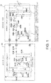
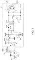
- Fig. 1 is a schematic view of a configuration circuit of a refrigeration cycle apparatus according to Embodiment 1 which does not form part of the present claimed invention
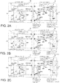
- Fig. 2A - 2C are diagrams showing combinations of faultily wired cables of a heat source side unit of an outdoor unit and a user side unit of an indoor unit, and
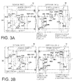
- Fig. 3A - 3B are diagrams showing combinations of faultily wired cables of the heat source side unit of the outdoor unit and the user side unit of the indoor unit.
- S1, S2, and S3 are terminal numbers of terminal boards of the heat source side unit 51 of the outdoor unit and the user side unit 52 of the indoor unit, and the cables are normally wired when they are wired so that the terminal numbers of the indoor unit agree with those of the outdoor unit.
- An external alternating current source 1 of the heat source side unit 51 is connected to both the ends of a power supply circuit 2 disposed in the heat source side unit 51.
- a diode D602, a resistor R607, and a zener diode ZD602, which are connected in series, are connected in parallel to both the ends of the power supply circuit 2, a connection point, at which the power supply circuit 2 is connected to the diode D602, is connected to a terminal S1, and a connection point, at which the power supply circuit 2 is connected to the zener diode ZD602, is connected to a terminal S2.
- a capacitor C603 is connected in parallel to both the ends of the zener diode ZD602, and a communication power supply creation circuit 3 is composed of the diode D602, resistor R607, zener diode ZD602, and capacitor C603.
- a transmission photocoupler PC602, a reception photocoupler PC601, a diode D601, and a resistor R601 are connected in series in this order from the connection point of the resistor R607 and the zener diode ZD602, and the other end of the resistor R601 is connected to a terminal S3 of a terminal board. Further, a resistor R602 and a capacitor C602 are connected in parallel to both the ends of the reception photocoupler PC601, respectively. Then, a resistor R605, a diode D605, and a resistor R603, which are connected in series, are connected between the terminal S3 and the terminal S2.
- a photocoupler PC603 is connected in parallel to both the ends of the resistor R603, and a faulty connection detecting circuit 4 is composed of the resistor R605, diode D605, resistor R603, photocoupler PC603, and other parts which are not shown in Fig. 1 .
- a resistor R132, a diode D132, a reception photocoupler IC132, and a transmission photocoupler IC131 are connected in series in this order from the terminal S3 and finally connected to the terminal S2 to thereby constitute a communication circuit. Further, a diode D131 and a capacitor C134 are connected in parallel to both the ends of the reception photocoupler IC132 and the transmission photocoupler IC131 connected in series. Then, a resistor R133 and a capacitor C133 are connected in parallel to both the ends of the reception photocoupler IC132, respectively.
- a power supply circuit 11 is connected to the terminals S1 and S2. Further, a diode D122, a resistor R121, and a diode D121, which are connected in series, are connected in parallel to both the ends of the power supply circuit 11. Then, a photocoupler IC121 is connected to both the ends of the diode D122, and a zero cross circuit 12 is composed of the diode D122, resistor R121, diode D121, photocoupler IC121, and parts composed of other parts which are not shown in Fig. 1 .
- the alternating current source 1 supplies an alternating voltage to the power supply circuit 2 which creates a direct voltage to be supplied to internal IC parts and the like. Further, the alternating voltage supplied by the alternating current source 1 is half-wave rectified by the diode D602 and the half-wave rectified current is restricted by the resistor R607. Then, a constant voltage is created by the zener diode ZD602 and further smoothed by the capacitor C603, thereby a communication power supply of about 25V is created.
- a current loop is formed by the circuit configuration in the heat source side unit 51 and the user side unit 52 and the paths in which the terminals S3, S3 and the terminals S2, S2 are connected to each other. Further, the resistor R601 in the heat source side unit 51 and the resistor R132 in the user side unit 52 restrict a current flowing in the current loop to thereby suppress an excess current. Further, the diode D601 in the heat source side unit 51 and the diode D132 in the user side unit 52 restrict the direction of the current of the current loop.
- the transmission photocoupler PC602 in the heat source side unit 51 and the transmission photocoupler IC131 in the user side unit 52 generates an ON and OFF state of the current flowing in the current loop, and the heat source side unit 51 and the user side unit 52 communicate with each other when the reception photocoupler PC601 in the heat source side unit 51 and the reception photocoupler IC132 in the user side unit 52 detect the ON/OFF of the current.
- the faulty connection detecting circuit 4 detects faulty connection to the alternating current source and to the ground in the heat source side unit 51.
- the zero cross circuit 12 detects a zero cross point of an alternating voltage that is input between the terminals S1 and S2 of the user side unit 52 from the heat source side unit 51. Then, the alternating voltage is supplied from the terminals S1 and S2 to the power supply circuit 11 to thereby create a direct voltage to be supplied to the internal IC parts and the like.
- an alternating voltage may be applied to a low voltage circuit portion, i.e., a communication circuit of the user side unit 52 due to faulty wiring among the terminals S1, S2, and S3 of the indoor unit and the outdoor unit (refer to Fig. 2B and Fig. 3A ).
- a high voltage withstanding photocoupler is used as the transmission photocoupler IC131 to protect the diode D131 and the diode D132 so that a current does not flow thereto.
- the transmission photocoupler IC131 is turned ON in the state that the alternating voltage is applied, there is a possibility that parts used in the communication circuit are broken. Accordingly, it is necessary to prevent the transmission photocoupler IC131 from being turned ON at the time of faulty wiring.
- the transmission photocoupler IC131 As one of method of the prevention, it is possible to prevent the transmission photocoupler IC131 from being turned ON by detecting that faulty wiring among the terminals S1, S2, and S3 of the indoor unit and the outdoor unit by also using the zero cross circuit 12 used for a different object such as a cutoff of the alternating voltage input, a long time timer, and the like.
- the zero cross circuit 12 used for a different object such as a cutoff of the alternating voltage input, a long time timer, and the like.
- no alternating voltage is applied to the zero cross circuit 12 and its zero cross detection output is not input to a microcomputer (not shown). Since it can be judged by the above operation that it is faulty wiring, the communication circuit can be protected by preventing the transmission photocoupler IC131 from being turned ON.
- the communication circuit can be protected by detecting faulty wiring among the terminals S1, S2, and S3 of the indoor unit and the outdoor unit by diverting the zero cross circuit 12 for a different object and preventing the transmission photocoupler IC131 from being turned ON. Further, since it is not necessary to add new parts only for the purpose of protecting the faulty wiring, faulty wiring can be protected without increasing a space at free of cost.
- the heat source side unit 51 of the outdoor unit receives an alternating voltage from the alternating current source 1, the communication power supply is created by the communication power supply creation circuit 3 disposed therein, and the user side unit 52 of the indoor unit includes the zero cross circuit 12.
- the user side unit 52 of the indoor unit may receive an alternating voltage from the alternating current source 1, the communication power supply creation circuit 3 may be disposed therein, and the heat source side unit 51 of the outdoor unit may include the zero cross circuit 12.
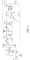
- Fig. 4 is a schematic view of a power supply circuit 11 of a user side unit 52 of an indoor unit of a refrigeration cycle apparatus according to Embodiment 2, showing only minimum parts. A configuration and an operation which are different from those of Embodiment 1 described above will be mainly explained below. In Embodiment 2, a method of protecting faulty wiring among terminals S1, S2, and S3 of an indoor unit and an outdoor unit when no zero cross circuit 12 is installed will be explained.
- the terminals S1 and S2 of the user side unit 52 are connected to an input side of a diode bridge DB1.
- a smoothing capacitor C111 is connected in parallel to an output end of the diode bridge DB1.
- a primary side of a transformer T111 and a switching element IC111 which are connected in series, are connected in parallel to both the ends of the smoothing capacitor C111.
- a secondary side of the transformer T111 i.e., one end of the output end of the transformer T111 is connected to an input terminal of a three-terminal regulator IC112 through a diode P113.
- a smoothing capacitor C113 is connected to the input terminal of the three-terminal regulator IC112 and to the other end of the output ends of the transformer T111, and the other end of the output ends of the transformer T111 is connected to a COM terminal of the three-terminal regulator IC112.
- a load resistor R1 is connected in parallel to both the ends of the smoothing capacitor C113.
- an output terminal of the three-terminal regulator IC112 is connected to one end of a smoothing capacitor C116, and the other end thereof is connected to the COM terminal of the three-terminal regulator IC112 and grounded. Further, the output terminal of the three-terminal regulator IC112 is connected to a microcomputer 21 and a reset IC 22, and an output terminal of the reset IC 22 is connected to the microcomputer 21.
- An alternating voltage is supplied between the terminals S1 and S2 of the user side unit 52 from the terminal S1 and S2 of the heat source side unit 51, input to the diode bridge DB1, and all-wave rectified therein. Then, the all-wave rectified voltage is smoothed by the smoothing capacitor C111. Further, when the voltage between both the ends of the smoothing capacitor C111 reaches a predetermined voltage, the switching element IC111 becomes a switching ON state so that electrical power energy is transferred to the secondary side through the transformer T111.
- a voltage transmitted from the primary side through the transformer T111 is half-wave rectified by a diode D113.
- the half-wave rectified voltage is smoothed by the smoothing capacitor C113 and creates a VDD12V power supply at both the ends of the smoothing capacitor C113.
- the voltage of the VDD12V power supply is dropped by the three-terminal regulator IC112 to create a VDD5V power supply, which is a microcomputer drive power supply.
- the VDD5V power supply is smoothed by the smoothing capacitor C116.
- a reset IC 22 monitors the microcomputer drive power supply VDD5V, and when its voltage is lower than a predetermined voltage, the reset IC 22 outputs a reset signal to the microcomputer 21 so that it is not driven.
- an alternating voltage is not directly input between terminals S1 and S2 of the user side unit 52.
- a communication power supply is input to an alternating voltage terminal at the user side unit 52 side in Fig. 2B and Fig. 3B , and is input thereto through a faulty connection detecting circuit in Fig. 2C and Fig. 3B .
- the switching element IC111 is intermittently switched in such a manner that the turned-ON state of the switching element IC111 does not continue and a switching operation is resumed when the voltage between both the ends of the smoothing capacitor C111 is set to a predetermined voltage necessary to start the switching element IC111 again.
- the voltage on the secondary side is not stabilized because it is periodically charged and discharged repeatedly.
- Ch1 is set to VDD12V
- Ch2 is set to VDD5V
- Ch3 is set to an output of the reset IC 22 (Hi is in a reset release state).
- Vdd12V does not sufficiently rise in the state that the power supply capability is poor at the time of faulty wiring. Further, VDD5D created based thereon comes not to sufficiently rise as well, so that it is possible to make reset not to be released by suppressing VDD5V lower than a voltage for releasing the reset IC22 (hereinafter, a reset release voltage).
- a difference in the input voltage and output voltage of a three-terminal regulator is about 2 V.
- the reset IC 22 when the reset release voltage of the reset IC 22 is set to 4 V, the reset IC 22 can be prevented from executing a reset operation by connecting the load resistor R1 for setting the MAX value of VDD12V to 6 V or less when the power supply capability is very low in the case of the faulty wiring.
- a voltage which is divided by the faulty connection detecting circuit 4 and the impedance of the power supply circuit 11 in the user side unit 52, is applied to the terminals S1 and S2 of the user side unit 52.
- a resistor R605 has a large resistance value of 100 k ⁇ , the voltage applied to the terminals S1 and S2 of the user side unit 52 is suppressed to a low level, and a current is also greatly reduced in addition. Accordingly, since a power supply capability to the user side unit 52 is very low like the case of the faultily wired states of Fig. 2B and Fig. 3B , rising of VDD12V and VDD5V due to the supply of the power is suppressed by connecting the load resistor R1 so that it is possible to make the reset release by the reset IC22 not to be executed.
- the load resistor R1 must be set to a value that causes no problem when the power supply rises at the time of normal wiring as shown in Fig. 1 , however, the value can be set without problem because the power supply capability has an apparent difference in the normally wired states shown in Fig. 1 and the faultily wired states shown in Fig 2B and Fig. 2C and Fig 3A and Fig. 3B . Further, in the faultily wired state of Fig. 2A , no alternating voltage as a high voltage is applied to the communication circuit, no destruction therein.
- the heat source side unit 51 in the outdoor unit receives an alternating voltage from an alternating power supply 1 and supplies it to the user side unit 52 in the indoor unit, and the user side unit 52 in the indoor unit has the power supply circuit 11 for enabling the protection of the faultily wiring described above.
- the user side unit 52 in the indoor unit may receive an alternating voltage from the alternating power supply 1 and supply it to the heat source side unit 51 in the outdoor unit, and the power supply circuit 2 of the heat source side unit 51 in the outdoor unit can protect the faulty wiring mentioned above.
- Embodiment 3 An configuration and an operation which are different from those of Embodiment 2 will be mainly explained in the following explanation of Embodiment 3.
- a load resistor R2 is connected in parallel to both the ends of a smoothing capacitor C111 on its primary side in Embodiment 3 as shown in Fig. 4 .
- a switching element IC111 can be made to be a switching OFF state by providing an appropriate resistor as the load resistor R2 and sufficiently suppressing rising of a voltage between both the ends of the smoothing capacitor C111.
- Embodiments 2 and 3 it is also possible to protect the faulty wiring by combining Embodiments 2 and 3.
- Fig. 6A - 6B are voltage waveform diagrams of a secondary side when a delay is provided until a reset is released at the time of faulty wiring in a refrigeration cycle apparatus according to Embodiment 4.
- Embodiment 4 A configuration and an operation which are different from those of Embodiments 2 and 3 will be mainly explained in the following explanation of Embodiment 4.
- the load resistor R1 is provided in Embodiment 2 and the load resistor R2 is provided in Embodiment 3 so that a reset is not released by the reset IC22.
- a delay is provided until the reset IC 22 releases a reset after VDD5V reaches a reset release voltage. With this operation, in a minute time during which VDD5V becomes equal to or higher than the reset release voltage, it is possible to prevent the reset IC 22 from releasing the reset.
- VDD5V is set equal to or higher than the reset release voltage as shown in Fig. 6A - 6B , it can be confirmed that the reset is not released by the provision of the delay.
- the delay of the reset release time must be suppressed within a time by which a control is not interfered at the time of normal wiring.
- provision of the delay can prevent the reset IC22 from releasing the reset, the load resistor R1 or R2 can be set to a high resistance value, and power consumed by these load resistors can be suppressed at the time of normal wiring.
- Fig. 7 is a power supply circuit diagram when a load resistor is caused to consume no power while a refrigeration cycle apparatus according to Embodiment 5 is operated in the case of normal wiring.
- Embodiment 5 A configuration and an operation which are different from those of Embodiments 2 to 4 described above will be mainly explained in the following explanation of Embodiment 5.
- an output terminal of a 3-terminal regulator IC112 is connected to an emitter of a PNP transistor Q1. Further, a collector of the PNP transistor Q1 is connected to a base of an NPN transistor Q2. Further, the other end of a load resistor R1 having one end connected to an input terminal of the 3-terminal regulator IC112 is connected to a collector of the NPN transistor Q2. Then, an emitter of the NPN transistor Q2 is connected to one end of a smoothing capacitor C113 as well as to the ground. Further, an output terminal of the reset IC 22 and a microcomputer 21 are connected to a base of the PNP transistor Q1.
- VDD5V When VDD5V is equal to or lower than a reset release voltage at the time of power-on, an output of the reset IC 22 is Lo and it is transmitted to the microcomputer 21 so that the device is in a reset state.
- VDD5V When VDD5V is increased to a certain voltage, the voltage between the base and the emitter of the PNP transistor is increased and the PNP transistor becomes ON state. Then, the base of the NPN transistor Q2 becomes Hi, the voltage between the base and the emitter of the NPN transistor Q2 is increased, and the NPN transistor becomes ON state.
- the above circuit configuration can be realized only by adding two transistors and the load resistor R1, and space saving and cost reduction can be realized.
- Embodiments 2 to 4 it is also possible to protect the faulty wiring by combining Embodiments 2 to 4 and Embodiment 5.
- Fig. 8 is a view showing a communication start delay time provided by a program of a microcomputer 21 in a refrigeration cycle apparatus according to Embodiment 6.
- Embodiment 6 A configuration and an operation which are different from those of Embodiment 2 will be mainly explained in the following explanation of Embodiment 6.
- Embodiment 2 to prevent a reset from being released by the reset IC 22, a rising of VDD5V is suppressed by disposing the load resistor R1 so that the reset is not released by the reset IC 22.
- the rising of VDD5V itself is not suppressed by hardware such as electronic parts and the like, but a predetermined delay time, i.e., a communication start delay time t is provided before a communication star by the program of the microcomputer 21 after a reset is released by the reset IC 22 in response to the rising of the VDD5V. Since a power supply capability is low in the faultily wired states shown in Fig. 2B and Fig. 2C and Fig. 3A and Fig. 3B by providing the communication start delay time t, the VDD5V drops during the communication start delay time t so that the device becomes a reset state again.
- a transmission photocoupler IC131 does not turn ON and a communication circuit can be protected.
- Embodiments 2 to 5 It is also possible to protect the faulty wiring by combining Embodiments 2 to 5 and Embodiment 6.
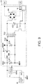
- Fig. 9 is a schematic view of a configuration circuit of a refrigeration cycle apparatus according to Embodiment 7.
- Embodiment 7 A configuration and an operation which are different from those of Embodiment 2 described above will be mainly explained in the following explanation of Embodiment 7.
- a low input voltage detection means 31 which detects a rectified and smoothed voltage, is connected in parallel to a capacitor C111, and wiring is executed so that a switching element IC111 can be turned on and off in response to a voltage detected thereby.
- An existing switching element may have a low input voltage detection function and becomes switching OFF state when detecting a low voltage, it is also possible to use it.
- the function can be used without adding a sensing resistor or an additional part, space saving and cost reduction can be realized.
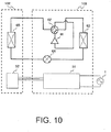
- Fig. 10 shows an example of a configuration view when a refrigeration cycle apparatus according to any of Embodiments 1 to 7 is mounted on an air conditioner.
- a flow path of a refrigerant circulating in the refrigeration cycle of the air conditioner according to Embodiment 8 passes firstly from a compressor 61 of an outdoor unit 101 through a 4-way valve 62, a first heat exchanger 63, and an expansion valve 64 and flows out to the outside of the outdoor unit 101.
- the refrigerant flowed out to the outside of the outdoor unit 101 flows out to the outside of an indoor unit 102 through a second heat exchanger 65 in the indoor unit 102. Then, the refrigerant which is flowed out to the outside of the indoor unit 102 returns again to the compressor 61 through the 4-way valve 62 in the outdoor unit 101.
- Heat exchange with an external air is performed in the first heat exchanger 63, and heat exchange with an indoor air is performed in the second heat exchanger 65.
- a heat source side unit 51 is disposed in the outdoor unit 101, and an alternating voltage is supplied from an external alternating current source 1. Further, a user side unit 52 is installed in the indoor unit 102 and electrically connected to the heat source side unit 51 in the outdoor unit 101 according to the configurations explained in Embodiments 1 to 7.
- the air conditioner can be obtained which is provided with the refrigeration cycle apparatus in which faulty wiring is protected as explained in Embodiments 1 to 7.
- the configuration of the air conditioner shown in Fig. 10 is only an example, and the refrigeration cycle apparatuses according to Embodiments 1 to 7 having a different configuration may be mounted thereon.
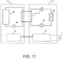
- Fig. 11 shows an example of an configuration view when the refrigeration cycle apparatus according to any of Embodiments 1 to 7 is mounted on a water heater.
- a refrigeration cycle is composed of a compressor 61, a radiator 67, an expansion valve 64 and an evaporator 66.
- a refrigerant flow path circulating in the refrigeration cycle passes from the compressor 61 through the radiator 67, the expansion valve 64, and the evaporator 66, and returns to the compressor 61 again.
- a water circulation cycle is composed of a pump 69, a radiator 67, and a tank 68.
- a water flow path circulating in the water circulation cycle passes from the pump 69 through the radiator 67 and the tank 68 and returns to the pump 69 again.
- the water in the water circulation cycle is supplied with heat energy from the refrigerant in the refrigeration cycle through the radiator 76 and heated water is stored in the tank 68.
- the heat source side unit 51 is installed in the refrigeration cycle unit 111 and supplied with an alternating voltage from the external alternating current source 1. Further, the user side unit 52 is installed in the heat accumulation circuit unit 112 and electrically connected to the heat source side unit 51 in the refrigeration cycle unit 111 according to the configurations explained in Embodiments 1 to 7.
- the water heater can be obtained which is provided with the refrigeration cycle apparatus in which faulty wiring is protected as explained in Embodiments 1 to 7.
- the configuration of the water heater shown in Fig. 11 is only an example and the refrigeration cycle apparatuses according to Embodiments 1 to 7 having a different configuration may be mounted thereon.
Landscapes
- Engineering & Computer Science (AREA)
- Mechanical Engineering (AREA)
- General Engineering & Computer Science (AREA)
- Chemical & Material Sciences (AREA)
- Combustion & Propulsion (AREA)
- Physics & Mathematics (AREA)
- Thermal Sciences (AREA)
- Air Conditioning Control Device (AREA)
- Steam Or Hot-Water Central Heating Systems (AREA)
Claims (4)
- Appareil à cycle de réfrigération comprenant une unité côté utilisateur (52) et une unité côté source de chaleur (51) connectées par au moins trois câbles à travers chaque extrémité de connexion, dans lequel
l'unité côté utilisateur (52) et l'unité côté source de chaleur (51) présentent un circuit de communication, respectivement ;
l'une ou l'autre de l'unité côté utilisateur (52) et de l'unité côté source de chaleur (51) reçoit une tension alternative en provenance d'une source de courant alternatif (1) ;
avec l'autre unité de l'unité côté utilisateur (52) et de l'unité côté source de chaleur (51), une puissance électrique est fournie par le biais des extrémités de connexion à l'aide de deux câbles des trois câbles en tant que lignes de courant alternatif, et une boucle de courant est formée et une communication est exécutée par le biais des extrémités de connexion à l'aide de l'autre câble et l'une des lignes de courant alternatif en tant que lignes de communication constituant le circuit de communication,
dans lequel l'autre unité comporte :un microordinateur (21) pour commander le circuit de communication ;un circuit d'alimentation en puissance (2, 11) pour convertir une tension alternative fournie depuis les câbles de courant alternatif en une tension continue d'alimentation en puissance de pilotage de microordinateur ; caractérisé en ce que ladite autre unité comporte en outre :des moyens de réinitialisation (22) pour surveiller la tension d'alimentation en puissance de pilotage de microordinateur fournie au microordinateur (21) et réinitialisent le microordinateur (21) lorsque la tension d'alimentation en puissance de pilotage de microordinateur est inférieure à une tension prédéterminée de sorte que le microordinateur (21) n'est pas piloté,dans lequel lorsque les trois câbles sont câblés de façon défectueuse, les moyens de réinitialisation (22) coupent le circuit de communication en gardant le microordinateur (21) dans un état réinitialisé de sorte que le pilotage du microordinateur (21) est vérifié en libérant une réinitialisation après qu'un délai prédéterminé s'écoule depuis que la tension d'alimentation en puissance de pilotage de microordinateur a dépassé la tension prédéterminée. - Appareil à cycle de réfrigération selon la revendication 1, dans lequel le microordinateur (21) amène le circuit de communication à démarrer une communication après qu'un délai prédéterminé s'est écoulé depuis qu'une réinitialisation est libérée par les moyens de réinitialisation (22).
- Climatiseur sur lequel est monté l'appareil à cycle de réfrigération de l'une quelconque des revendications 1 et 2.
- Chauffe-eau sur lequel est monté l'appareil à cycle de réfrigération de l'une quelconque des revendications 1 et 2.
Applications Claiming Priority (1)
| Application Number | Priority Date | Filing Date | Title |
|---|---|---|---|
| JP2008276083A JP4740991B2 (ja) | 2008-10-27 | 2008-10-27 | 冷凍サイクル装置、並びにそれを備えた空気調和機及び給湯器 |
Publications (3)
| Publication Number | Publication Date |
|---|---|
| EP2180263A2 EP2180263A2 (fr) | 2010-04-28 |
| EP2180263A3 EP2180263A3 (fr) | 2015-01-14 |
| EP2180263B1 true EP2180263B1 (fr) | 2019-09-25 |
Family
ID=41665363
Family Applications (1)
| Application Number | Title | Priority Date | Filing Date |
|---|---|---|---|
| EP09166564.6A Active EP2180263B1 (fr) | 2008-10-27 | 2009-07-28 | Appareil à cycle de réfrigération et climatiseur d'air et chauffe-eau dotés de celui-ci |
Country Status (3)
| Country | Link |
|---|---|
| EP (1) | EP2180263B1 (fr) |
| JP (1) | JP4740991B2 (fr) |
| ES (1) | ES2751323T3 (fr) |
Families Citing this family (4)
| Publication number | Priority date | Publication date | Assignee | Title |
|---|---|---|---|---|
| KR101295057B1 (ko) | 2011-12-09 | 2013-08-08 | 엘지전자 주식회사 | 공기 조화기 및 이의 통신 장치 |
| CN102607104B (zh) * | 2011-12-31 | 2014-01-01 | 海信科龙电器股份有限公司 | 一种宽电压空调器 |
| US20160327284A1 (en) | 2013-09-24 | 2016-11-10 | Energen Chile S.A. | Modular hydrotherm and operation method |
| WO2022190229A1 (fr) * | 2021-03-10 | 2022-09-15 | 三菱電機株式会社 | Dispositif de climatisation du type à divisions multiples et procédé de détermination de connexion |
Family Cites Families (10)
| Publication number | Priority date | Publication date | Assignee | Title |
|---|---|---|---|---|
| JPS62129641A (ja) * | 1985-11-29 | 1987-06-11 | Mitsubishi Electric Corp | 空気調和機の制御装置 |
| JP2855932B2 (ja) * | 1992-02-03 | 1999-02-10 | ダイキン工業株式会社 | 空気調和装置の運転制御装置 |
| JP2916656B2 (ja) * | 1992-10-12 | 1999-07-05 | シャープ株式会社 | 空気調和機 |
| JPH07217972A (ja) | 1994-02-02 | 1995-08-18 | Hitachi Ltd | 空気調和機の制御装置 |
| JP3656478B2 (ja) * | 1999-09-22 | 2005-06-08 | 三菱電機株式会社 | 電源高調波抑制装置 |
| JP4288831B2 (ja) * | 2000-06-14 | 2009-07-01 | 三菱電機株式会社 | セパレート形空気調和機の制御回路 |
| JP2004070767A (ja) * | 2002-08-08 | 2004-03-04 | Canon Inc | 制御装置 |
| JP4599910B2 (ja) * | 2004-07-01 | 2010-12-15 | ダイキン工業株式会社 | 給湯装置 |
| JP2006284104A (ja) * | 2005-04-01 | 2006-10-19 | Hitachi Home & Life Solutions Inc | 空気調和機の通信装置 |
| JP2007298237A (ja) * | 2006-05-01 | 2007-11-15 | Denso Corp | 電力制御システム及び電力制御方法 |
-
2008
- 2008-10-27 JP JP2008276083A patent/JP4740991B2/ja not_active Expired - Fee Related
-
2009
- 2009-07-28 ES ES09166564T patent/ES2751323T3/es active Active
- 2009-07-28 EP EP09166564.6A patent/EP2180263B1/fr active Active
Non-Patent Citations (1)
| Title |
|---|
| None * |
Also Published As
| Publication number | Publication date |
|---|---|
| JP4740991B2 (ja) | 2011-08-03 |
| EP2180263A3 (fr) | 2015-01-14 |
| EP2180263A2 (fr) | 2010-04-28 |
| ES2751323T3 (es) | 2020-03-31 |
| JP2010101609A (ja) | 2010-05-06 |
Similar Documents
| Publication | Publication Date | Title |
|---|---|---|
| JP6578111B2 (ja) | 絶縁型のdc/dcコンバータおよびそのフィードバック回路、それを用いた電源装置、電源アダプタおよび電子機器 | |
| TWI483513B (zh) | 裝備電源供應單元之電氣裝置 | |
| US20100287399A1 (en) | Usb power supply circuit | |
| US8738954B2 (en) | Power source circuit and control method thereof | |
| CN106403142A (zh) | 多联机空调系统室内机异常断电保护方法 | |
| US20140339996A1 (en) | Ballast and ballast control method and apparatus, for example anti-arcing control for electronic ballast | |
| KR100353326B1 (ko) | 컴퓨터 주변기기의 절전장치 및 절전방법 | |
| US20170264091A1 (en) | Overvoltage recovery circuit and a controller and hvac system including the same | |
| KR101633297B1 (ko) | 전자 디바이스의 대기전력 감소를 위한 전원공급장치 및 방법 | |
| EP2180263A2 (fr) | Appareil à cycle de réfrigération et climatiseur d'air et chauffe-eau dotés de celui-ci | |
| CN102376152A (zh) | 遥控器及具备该遥控器的空气调节器 | |
| US20220209571A1 (en) | Devices, systems, and methods for reducing standby power consumption | |
| CN109888717A (zh) | 一种逆变焊机的温度保护电路 | |
| CN206353706U (zh) | 一种电器设备及其掉电保护电路 | |
| US20120293903A1 (en) | Power supply apparatus with inrush current prevention circuit | |
| US20100315058A1 (en) | Power supply apparatus with inrush current prevention circuit | |
| JP4474382B2 (ja) | ディスプレイデバイスの電力制御回路 | |
| KR101702081B1 (ko) | 이중 전원 공급 장치 | |
| EP4343341B1 (fr) | Circuit de détection de panne de courant et circuit de commande pour système à écoulement de fluide frigorigène variable | |
| JP5235978B2 (ja) | 冷凍サイクル装置、並びにそれを備えた空気調和機及び給湯器 | |
| CN108027159A (zh) | 空气调节机以及空气调节机的控制方法 | |
| KR100771622B1 (ko) | 피에프씨 과전압 차단장치 | |
| KR101946374B1 (ko) | 대기 전력 기능을 가지는 전원 장치 및 그 제어 방법 | |
| KR20130076295A (ko) | 전원 공급 장치 | |
| JPH08107697A (ja) | Dcファンモータの異常検出回路 |
Legal Events
| Date | Code | Title | Description |
|---|---|---|---|
| PUAI | Public reference made under article 153(3) epc to a published international application that has entered the european phase |
Free format text: ORIGINAL CODE: 0009012 |
|
| AK | Designated contracting states |
Kind code of ref document: A2 Designated state(s): AT BE BG CH CY CZ DE DK EE ES FI FR GB GR HR HU IE IS IT LI LT LU LV MC MK MT NL NO PL PT RO SE SI SK SM TR |
|
| AX | Request for extension of the european patent |
Extension state: AL BA RS |
|
| PUAL | Search report despatched |
Free format text: ORIGINAL CODE: 0009013 |
|
| AK | Designated contracting states |
Kind code of ref document: A3 Designated state(s): AT BE BG CH CY CZ DE DK EE ES FI FR GB GR HR HU IE IS IT LI LT LU LV MC MK MT NL NO PL PT RO SE SI SK SM TR |
|
| AX | Request for extension of the european patent |
Extension state: AL BA RS |
|
| 17P | Request for examination filed |
Effective date: 20150601 |
|
| RBV | Designated contracting states (corrected) |
Designated state(s): AT BE BG CH CY CZ DE DK EE ES FI FR GB GR HR HU IE IS IT LI LT LU LV MC MK MT NL NO PL PT RO SE SI SK SM TR |
|
| STAA | Information on the status of an ep patent application or granted ep patent |
Free format text: STATUS: EXAMINATION IS IN PROGRESS |
|
| 17Q | First examination report despatched |
Effective date: 20180316 |
|
| REG | Reference to a national code |
Ref country code: DE Ref legal event code: R079 Ref document number: 602009059940 Country of ref document: DE Free format text: PREVIOUS MAIN CLASS: F24F0001000000 Ipc: F24F0001220000 |
|
| GRAP | Despatch of communication of intention to grant a patent |
Free format text: ORIGINAL CODE: EPIDOSNIGR1 |
|
| STAA | Information on the status of an ep patent application or granted ep patent |
Free format text: STATUS: GRANT OF PATENT IS INTENDED |
|
| RIC1 | Information provided on ipc code assigned before grant |
Ipc: F24F 11/00 20180101ALI20190308BHEP Ipc: F24F 1/22 20110101AFI20190308BHEP Ipc: F25B 49/00 20060101ALI20190308BHEP |
|
| INTG | Intention to grant announced |
Effective date: 20190405 |
|
| GRAS | Grant fee paid |
Free format text: ORIGINAL CODE: EPIDOSNIGR3 |
|
| GRAA | (expected) grant |
Free format text: ORIGINAL CODE: 0009210 |
|
| STAA | Information on the status of an ep patent application or granted ep patent |
Free format text: STATUS: THE PATENT HAS BEEN GRANTED |
|
| AK | Designated contracting states |
Kind code of ref document: B1 Designated state(s): AT BE BG CH CY CZ DE DK EE ES FI FR GB GR HR HU IE IS IT LI LT LU LV MC MK MT NL NO PL PT RO SE SI SK SM TR |
|
| REG | Reference to a national code |
Ref country code: GB Ref legal event code: FG4D |
|
| REG | Reference to a national code |
Ref country code: CH Ref legal event code: EP |
|
| REG | Reference to a national code |
Ref country code: AT Ref legal event code: REF Ref document number: 1184180 Country of ref document: AT Kind code of ref document: T Effective date: 20191015 |
|
| REG | Reference to a national code |
Ref country code: IE Ref legal event code: FG4D |
|
| REG | Reference to a national code |
Ref country code: DE Ref legal event code: R096 Ref document number: 602009059940 Country of ref document: DE |
|
| REG | Reference to a national code |
Ref country code: NL Ref legal event code: MP Effective date: 20190925 |
|
| PG25 | Lapsed in a contracting state [announced via postgrant information from national office to epo] |
Ref country code: FI Free format text: LAPSE BECAUSE OF FAILURE TO SUBMIT A TRANSLATION OF THE DESCRIPTION OR TO PAY THE FEE WITHIN THE PRESCRIBED TIME-LIMIT Effective date: 20190925 Ref country code: HR Free format text: LAPSE BECAUSE OF FAILURE TO SUBMIT A TRANSLATION OF THE DESCRIPTION OR TO PAY THE FEE WITHIN THE PRESCRIBED TIME-LIMIT Effective date: 20190925 Ref country code: SE Free format text: LAPSE BECAUSE OF FAILURE TO SUBMIT A TRANSLATION OF THE DESCRIPTION OR TO PAY THE FEE WITHIN THE PRESCRIBED TIME-LIMIT Effective date: 20190925 Ref country code: BG Free format text: LAPSE BECAUSE OF FAILURE TO SUBMIT A TRANSLATION OF THE DESCRIPTION OR TO PAY THE FEE WITHIN THE PRESCRIBED TIME-LIMIT Effective date: 20191225 Ref country code: LT Free format text: LAPSE BECAUSE OF FAILURE TO SUBMIT A TRANSLATION OF THE DESCRIPTION OR TO PAY THE FEE WITHIN THE PRESCRIBED TIME-LIMIT Effective date: 20190925 Ref country code: NO Free format text: LAPSE BECAUSE OF FAILURE TO SUBMIT A TRANSLATION OF THE DESCRIPTION OR TO PAY THE FEE WITHIN THE PRESCRIBED TIME-LIMIT Effective date: 20191225 |
|
| REG | Reference to a national code |
Ref country code: LT Ref legal event code: MG4D |
|
| PG25 | Lapsed in a contracting state [announced via postgrant information from national office to epo] |
Ref country code: LV Free format text: LAPSE BECAUSE OF FAILURE TO SUBMIT A TRANSLATION OF THE DESCRIPTION OR TO PAY THE FEE WITHIN THE PRESCRIBED TIME-LIMIT Effective date: 20190925 Ref country code: GR Free format text: LAPSE BECAUSE OF FAILURE TO SUBMIT A TRANSLATION OF THE DESCRIPTION OR TO PAY THE FEE WITHIN THE PRESCRIBED TIME-LIMIT Effective date: 20191226 |
|
| REG | Reference to a national code |
Ref country code: ES Ref legal event code: FG2A Ref document number: 2751323 Country of ref document: ES Kind code of ref document: T3 Effective date: 20200331 |
|
| REG | Reference to a national code |
Ref country code: AT Ref legal event code: MK05 Ref document number: 1184180 Country of ref document: AT Kind code of ref document: T Effective date: 20190925 |
|
| PG25 | Lapsed in a contracting state [announced via postgrant information from national office to epo] |
Ref country code: EE Free format text: LAPSE BECAUSE OF FAILURE TO SUBMIT A TRANSLATION OF THE DESCRIPTION OR TO PAY THE FEE WITHIN THE PRESCRIBED TIME-LIMIT Effective date: 20190925 Ref country code: PL Free format text: LAPSE BECAUSE OF FAILURE TO SUBMIT A TRANSLATION OF THE DESCRIPTION OR TO PAY THE FEE WITHIN THE PRESCRIBED TIME-LIMIT Effective date: 20190925 Ref country code: PT Free format text: LAPSE BECAUSE OF FAILURE TO SUBMIT A TRANSLATION OF THE DESCRIPTION OR TO PAY THE FEE WITHIN THE PRESCRIBED TIME-LIMIT Effective date: 20200127 Ref country code: RO Free format text: LAPSE BECAUSE OF FAILURE TO SUBMIT A TRANSLATION OF THE DESCRIPTION OR TO PAY THE FEE WITHIN THE PRESCRIBED TIME-LIMIT Effective date: 20190925 Ref country code: NL Free format text: LAPSE BECAUSE OF FAILURE TO SUBMIT A TRANSLATION OF THE DESCRIPTION OR TO PAY THE FEE WITHIN THE PRESCRIBED TIME-LIMIT Effective date: 20190925 Ref country code: AT Free format text: LAPSE BECAUSE OF FAILURE TO SUBMIT A TRANSLATION OF THE DESCRIPTION OR TO PAY THE FEE WITHIN THE PRESCRIBED TIME-LIMIT Effective date: 20190925 |
|
| PG25 | Lapsed in a contracting state [announced via postgrant information from national office to epo] |
Ref country code: CZ Free format text: LAPSE BECAUSE OF FAILURE TO SUBMIT A TRANSLATION OF THE DESCRIPTION OR TO PAY THE FEE WITHIN THE PRESCRIBED TIME-LIMIT Effective date: 20190925 Ref country code: IS Free format text: LAPSE BECAUSE OF FAILURE TO SUBMIT A TRANSLATION OF THE DESCRIPTION OR TO PAY THE FEE WITHIN THE PRESCRIBED TIME-LIMIT Effective date: 20200224 Ref country code: SK Free format text: LAPSE BECAUSE OF FAILURE TO SUBMIT A TRANSLATION OF THE DESCRIPTION OR TO PAY THE FEE WITHIN THE PRESCRIBED TIME-LIMIT Effective date: 20190925 Ref country code: SM Free format text: LAPSE BECAUSE OF FAILURE TO SUBMIT A TRANSLATION OF THE DESCRIPTION OR TO PAY THE FEE WITHIN THE PRESCRIBED TIME-LIMIT Effective date: 20190925 |
|
| REG | Reference to a national code |
Ref country code: DE Ref legal event code: R097 Ref document number: 602009059940 Country of ref document: DE |
|
| PG2D | Information on lapse in contracting state deleted |
Ref country code: IS |
|
| PG25 | Lapsed in a contracting state [announced via postgrant information from national office to epo] |
Ref country code: DK Free format text: LAPSE BECAUSE OF FAILURE TO SUBMIT A TRANSLATION OF THE DESCRIPTION OR TO PAY THE FEE WITHIN THE PRESCRIBED TIME-LIMIT Effective date: 20190925 Ref country code: IS Free format text: LAPSE BECAUSE OF FAILURE TO SUBMIT A TRANSLATION OF THE DESCRIPTION OR TO PAY THE FEE WITHIN THE PRESCRIBED TIME-LIMIT Effective date: 20200126 |
|
| PLBE | No opposition filed within time limit |
Free format text: ORIGINAL CODE: 0009261 |
|
| STAA | Information on the status of an ep patent application or granted ep patent |
Free format text: STATUS: NO OPPOSITION FILED WITHIN TIME LIMIT |
|
| 26N | No opposition filed |
Effective date: 20200626 |
|
| PG25 | Lapsed in a contracting state [announced via postgrant information from national office to epo] |
Ref country code: SI Free format text: LAPSE BECAUSE OF FAILURE TO SUBMIT A TRANSLATION OF THE DESCRIPTION OR TO PAY THE FEE WITHIN THE PRESCRIBED TIME-LIMIT Effective date: 20190925 |
|
| REG | Reference to a national code |
Ref country code: DE Ref legal event code: R119 Ref document number: 602009059940 Country of ref document: DE |
|
| PG25 | Lapsed in a contracting state [announced via postgrant information from national office to epo] |
Ref country code: MC Free format text: LAPSE BECAUSE OF FAILURE TO SUBMIT A TRANSLATION OF THE DESCRIPTION OR TO PAY THE FEE WITHIN THE PRESCRIBED TIME-LIMIT Effective date: 20190925 |
|
| REG | Reference to a national code |
Ref country code: CH Ref legal event code: PL |
|
| GBPC | Gb: european patent ceased through non-payment of renewal fee |
Effective date: 20200728 |
|
| REG | Reference to a national code |
Ref country code: BE Ref legal event code: MM Effective date: 20200731 |
|
| PG25 | Lapsed in a contracting state [announced via postgrant information from national office to epo] |
Ref country code: LI Free format text: LAPSE BECAUSE OF NON-PAYMENT OF DUE FEES Effective date: 20200731 Ref country code: CH Free format text: LAPSE BECAUSE OF NON-PAYMENT OF DUE FEES Effective date: 20200731 Ref country code: GB Free format text: LAPSE BECAUSE OF NON-PAYMENT OF DUE FEES Effective date: 20200728 Ref country code: LU Free format text: LAPSE BECAUSE OF NON-PAYMENT OF DUE FEES Effective date: 20200728 |
|
| PG25 | Lapsed in a contracting state [announced via postgrant information from national office to epo] |
Ref country code: DE Free format text: LAPSE BECAUSE OF NON-PAYMENT OF DUE FEES Effective date: 20210202 Ref country code: BE Free format text: LAPSE BECAUSE OF NON-PAYMENT OF DUE FEES Effective date: 20200731 |
|
| PG25 | Lapsed in a contracting state [announced via postgrant information from national office to epo] |
Ref country code: IE Free format text: LAPSE BECAUSE OF NON-PAYMENT OF DUE FEES Effective date: 20200728 |
|
| PG25 | Lapsed in a contracting state [announced via postgrant information from national office to epo] |
Ref country code: TR Free format text: LAPSE BECAUSE OF FAILURE TO SUBMIT A TRANSLATION OF THE DESCRIPTION OR TO PAY THE FEE WITHIN THE PRESCRIBED TIME-LIMIT Effective date: 20190925 Ref country code: MT Free format text: LAPSE BECAUSE OF FAILURE TO SUBMIT A TRANSLATION OF THE DESCRIPTION OR TO PAY THE FEE WITHIN THE PRESCRIBED TIME-LIMIT Effective date: 20190925 Ref country code: CY Free format text: LAPSE BECAUSE OF FAILURE TO SUBMIT A TRANSLATION OF THE DESCRIPTION OR TO PAY THE FEE WITHIN THE PRESCRIBED TIME-LIMIT Effective date: 20190925 |
|
| PG25 | Lapsed in a contracting state [announced via postgrant information from national office to epo] |
Ref country code: MK Free format text: LAPSE BECAUSE OF FAILURE TO SUBMIT A TRANSLATION OF THE DESCRIPTION OR TO PAY THE FEE WITHIN THE PRESCRIBED TIME-LIMIT Effective date: 20190925 |
|
| PGFP | Annual fee paid to national office [announced via postgrant information from national office to epo] |
Ref country code: IT Payment date: 20220613 Year of fee payment: 14 |
|
| PGFP | Annual fee paid to national office [announced via postgrant information from national office to epo] |
Ref country code: FR Payment date: 20220609 Year of fee payment: 14 |
|
| PGFP | Annual fee paid to national office [announced via postgrant information from national office to epo] |
Ref country code: ES Payment date: 20220801 Year of fee payment: 14 |
|
| P01 | Opt-out of the competence of the unified patent court (upc) registered |
Effective date: 20230512 |
|
| PG25 | Lapsed in a contracting state [announced via postgrant information from national office to epo] |
Ref country code: FR Free format text: LAPSE BECAUSE OF NON-PAYMENT OF DUE FEES Effective date: 20230731 |
|
| PG25 | Lapsed in a contracting state [announced via postgrant information from national office to epo] |
Ref country code: IT Free format text: LAPSE BECAUSE OF NON-PAYMENT OF DUE FEES Effective date: 20230728 |
|
| REG | Reference to a national code |
Ref country code: ES Ref legal event code: FD2A Effective date: 20240830 |
|
| PG25 | Lapsed in a contracting state [announced via postgrant information from national office to epo] |
Ref country code: ES Free format text: LAPSE BECAUSE OF NON-PAYMENT OF DUE FEES Effective date: 20230729 |
|
| PG25 | Lapsed in a contracting state [announced via postgrant information from national office to epo] |
Ref country code: ES Free format text: LAPSE BECAUSE OF NON-PAYMENT OF DUE FEES Effective date: 20230729 |