EP2180224A2 - Rohrverbindung - Google Patents
Rohrverbindung Download PDFInfo
- Publication number
- EP2180224A2 EP2180224A2 EP09174147A EP09174147A EP2180224A2 EP 2180224 A2 EP2180224 A2 EP 2180224A2 EP 09174147 A EP09174147 A EP 09174147A EP 09174147 A EP09174147 A EP 09174147A EP 2180224 A2 EP2180224 A2 EP 2180224A2
- Authority
- EP
- European Patent Office
- Prior art keywords
- sleeve
- pipe
- correcting member
- ring
- packing
- Prior art date
- Legal status (The legal status is an assumption and is not a legal conclusion. Google has not performed a legal analysis and makes no representation as to the accuracy of the status listed.)
- Granted
Links
Images


Classifications
-
- F—MECHANICAL ENGINEERING; LIGHTING; HEATING; WEAPONS; BLASTING
- F16—ENGINEERING ELEMENTS AND UNITS; GENERAL MEASURES FOR PRODUCING AND MAINTAINING EFFECTIVE FUNCTIONING OF MACHINES OR INSTALLATIONS; THERMAL INSULATION IN GENERAL
- F16L—PIPES; JOINTS OR FITTINGS FOR PIPES; SUPPORTS FOR PIPES, CABLES OR PROTECTIVE TUBING; MEANS FOR THERMAL INSULATION IN GENERAL
- F16L37/00—Couplings of the quick-acting type
- F16L37/08—Couplings of the quick-acting type in which the connection between abutting or axially overlapping ends is maintained by locking members
- F16L37/084—Couplings of the quick-acting type in which the connection between abutting or axially overlapping ends is maintained by locking members combined with automatic locking
- F16L37/092—Couplings of the quick-acting type in which the connection between abutting or axially overlapping ends is maintained by locking members combined with automatic locking by means of elements wedged between the pipe and the frusto-conical surface of the body of the connector
- F16L37/0925—Couplings of the quick-acting type in which the connection between abutting or axially overlapping ends is maintained by locking members combined with automatic locking by means of elements wedged between the pipe and the frusto-conical surface of the body of the connector with rings which bite into the wall of the pipe
-
- F—MECHANICAL ENGINEERING; LIGHTING; HEATING; WEAPONS; BLASTING
- F16—ENGINEERING ELEMENTS AND UNITS; GENERAL MEASURES FOR PRODUCING AND MAINTAINING EFFECTIVE FUNCTIONING OF MACHINES OR INSTALLATIONS; THERMAL INSULATION IN GENERAL
- F16L—PIPES; JOINTS OR FITTINGS FOR PIPES; SUPPORTS FOR PIPES, CABLES OR PROTECTIVE TUBING; MEANS FOR THERMAL INSULATION IN GENERAL
- F16L37/00—Couplings of the quick-acting type
- F16L37/08—Couplings of the quick-acting type in which the connection between abutting or axially overlapping ends is maintained by locking members
- F16L37/084—Couplings of the quick-acting type in which the connection between abutting or axially overlapping ends is maintained by locking members combined with automatic locking
- F16L37/088—Couplings of the quick-acting type in which the connection between abutting or axially overlapping ends is maintained by locking members combined with automatic locking by means of a split elastic ring
-
- F—MECHANICAL ENGINEERING; LIGHTING; HEATING; WEAPONS; BLASTING
- F16—ENGINEERING ELEMENTS AND UNITS; GENERAL MEASURES FOR PRODUCING AND MAINTAINING EFFECTIVE FUNCTIONING OF MACHINES OR INSTALLATIONS; THERMAL INSULATION IN GENERAL
- F16L—PIPES; JOINTS OR FITTINGS FOR PIPES; SUPPORTS FOR PIPES, CABLES OR PROTECTIVE TUBING; MEANS FOR THERMAL INSULATION IN GENERAL
- F16L37/00—Couplings of the quick-acting type
- F16L37/08—Couplings of the quick-acting type in which the connection between abutting or axially overlapping ends is maintained by locking members
- F16L37/084—Couplings of the quick-acting type in which the connection between abutting or axially overlapping ends is maintained by locking members combined with automatic locking
- F16L37/092—Couplings of the quick-acting type in which the connection between abutting or axially overlapping ends is maintained by locking members combined with automatic locking by means of elements wedged between the pipe and the frusto-conical surface of the body of the connector
- F16L37/0926—Couplings of the quick-acting type in which the connection between abutting or axially overlapping ends is maintained by locking members combined with automatic locking by means of elements wedged between the pipe and the frusto-conical surface of the body of the connector with an inner support sleeve arranged within the pipe
-
- F—MECHANICAL ENGINEERING; LIGHTING; HEATING; WEAPONS; BLASTING
- F16—ENGINEERING ELEMENTS AND UNITS; GENERAL MEASURES FOR PRODUCING AND MAINTAINING EFFECTIVE FUNCTIONING OF MACHINES OR INSTALLATIONS; THERMAL INSULATION IN GENERAL
- F16L—PIPES; JOINTS OR FITTINGS FOR PIPES; SUPPORTS FOR PIPES, CABLES OR PROTECTIVE TUBING; MEANS FOR THERMAL INSULATION IN GENERAL
- F16L2201/00—Special arrangements for pipe couplings
- F16L2201/10—Indicators for correct coupling
Definitions
- the present invention relates to a one-touch pipe joint which is used as a joint for water pipes or the like and which enables a joint connection simply by inserting a pipe such as a resin pipe,
- the pipe joint to which a pipe such as a resin pipe is joined simply by inverting the pipe.
- the pipe joint is configured such that, when a pipe 5 to be connected is fitted on a cylindrical sleeve X1 protruded from a joint main body X, O-ring packings 9 attached aground an outer peripheral surface of the sleeve X1 firmly contacts to seal the pipe 5, and serrations g 1 of a lock ring g bite into the pipe 5, whereby the pipe 5 is connected and joined to the pipe joint.
- the pipe 5 is, for example, wound into a roll having a diameter of about lm to be carried on a vehicle, and is stretched straight and cut into a required length when being used at a work site. However, even if the pipe 5 is stretched, it is sometimes not stretched sufficiently straight in which case the pipe 5 is obliquely cut. In a case in which the obliquely cut pipe 5 is fitted on the sleeve X1, the packing 9 may be upwardly distorted or damaged.
- JP2003-314775A proposes an insertion type pipe joint characterized in that a tapered ring has a forwardly widened tapered part which becomes narrower toward the rear from a front end portion of an inner peripheral surface thereof, wherein the minimum inner diameter of the tapered part is set equal to or smaller than the standard inner diameter of the pipe.
- JP2003-314775A describes that "while the minimum inner diameter of the tapered part 48 is set equal to the standard inner diameter of the pipe P, when a pipe P having an inner diameter which is the minimum inner diameter within tolerance is inserted as shown in Fig, 11 , an outer diameter portion of the elastic seal ring 32 cannot be pressed by the tapered ring 35 to become smaller than the inner diameter of the pipe P, which raises a problem that an inner diameter portion of the pipe P gets stuck against the outer diameter portion of the elastic seal ring 32 thereby impairing the insertion performance of the pipe P".
- the minimum inner diameter of the tapered part needs to be set equal to or smaller than the standard inner diameter of the pipe as described above, which requires severe precision.
- the tapered ring is a resin molded product, the range of elastic deformation of the tapered ring is limited. That is, although JP2003-314775A describes that "even if the pipe is cut obliquely to some extent, the tapered ring 22 deforms along the obliquely cut end face C of the pipe P", the allowable oblique angle of the cut end face is limited to a certain extent.
- the hollow shaft 15 is configured such that a, plurality of axially extending cutout portion 14 is formed in the circumference thereof at intervals in the circumferential direction so as to be expandable and shrinkable" as described in paragraph [0026] of JP2003-314775A , the elasticity deformable characteristic of the tapered ring gives rise to the following drawback.
- the elastically deformable tapered ring 22 may not "be pushed deep inside the pipe insertion space 12 by the cut end face of the one end portion of the pipe P such that the tapered part 24 of the tapered ring 22 contacts the outer peripheral portion of the elastic seal ring 2 protruding from the sealing groove 13 of the inner cylindrical member 5 and compresses the ring 22", but may outwardly expand in a radial direction by pushing expanding the hollow shaft 15, resulting in a difficulty in smoothly attaching the pipe P to the joint main body without butting against the elastic seal ring 32.
- the inner part 551 of the end face 55 of the pipe sometimes butt against the packing 9 and deforms the packing 9 into a shape 91 which impairs the sealing function of the packing 9, and in some cases, moreover, the inner part 551 of the end face 55 pushes out the packing 9 from a ring-shaped groove in which the packing 9 has been fitted
- recently used pipes are sometimes a metal composite pipe having a core member made of a metal such as aluminum and resin layers provided on the core member as inner and outer layers. In such a case, when the pipe is cut with a pipe cutter, the end face of the pipe becomes flattened into an elliptical shape. If the elliptical end face is left as it is, the pipe cannot be properly fitted on the sleeve,
- a pipe chamfering tool (a so-called hand taper reamer). More specifically, by using the pipe chamfering tool, the shape of the pipe end face 55 is corrected to be in a circular shape and the inner peripheral part of the pipe end face 55 is removed to provide a chamfered inner face 59 as shown in Fig. 14 , and thereafter, the pipe 5 is inserted along the sleeve X1 as shown in Fig. 15 .
- the present invention is made in view of the problems described above, and it is an object thereof to provide a pipe joint which enables, without a use of a chamfering tool for shaping and chamfering an end face of a pipe or any other preprocessing, and even if the pipe is cut obliquely, a joint connection by smoothly inserting the pipe along a sleeve directly after the cutting.
- a pipe joint comprises: a joint main body comprising a cylindrical sleeve having an outer peripheral surface along which a ring-shaped groove is formed, and a main portion from which the cylindrical sleeve protrudes; a packing which is fitted in the ring-shaped groove and is adapted to finally contact a.
- the correcting member is elastically deformable, and a hardness of the correcting member is set equal to or higher than a hardness of the packing.
- the cap nut comprises a cylindrical inner wall to which the correcting member lies close or contacts at least in a range in which the correcting member moves over a portion of the sleeve where the packing is fitted.
- the correcting member is elastiCally deformable, even when the pipe is cut obliquely, the correcting member elastically deforms accordingly, Therefore, the obliquely cut pipe can be directly and smoothly fitted onto the sleeve. Furthermore, because the hardness of the correcting member is set equal to or higher than the hardness of the packing, and the cap nut includes a cylindrical inner wall to which the correcting member lies close or contacts at least in the range in which the correcting member moves over a portion of the sleeve where the packing is fitted, the elastic packing can be effectively pressed and sulk into the ring-shaped groove using the external force applied to the sloped portion.
- the packing catches the sloped portion such that the small diameter portion is disposed on a side of the packing which is closer to a distal end of the sleeve.
- the sloped potion presses and deforms the packing to run over the packing and further moves award the base end of the sleeve.
- the pipe joint under the un-used condition before the pipe is connected to the pipe joint, the pipe joint is maintained in a state in which no load is applied so that the packing is not elastically compressed. Therefore, a long-term storage of the pipe joint is possible after assembling the pipe joint.
- a distal end portion of the sleeve comprises a tapered part having an outer diameter which gradually decreases toward the distal end of the sleeve.
- the taper part corrects the shape of the end face of the pipe to be in a circular shape.
- the pipe joint further comprises a lock ring having an outer diameter which is large than the inner diameter of the small diameter portion, A peripheral groove is formed in the outer peripheral surface of the sleeve at a location closer to the distil end of the sleeve than from a location where the correcting members is loosely fitted on the sleeve.
- the lock ring is fitted in the peripheral groove to stop a movement of the correcting member toward the distal end of the sleeve,
- the correcting member is prevented from dropping off the sleeve after assembling the pipe joint. Therefore, in addition to the advantage of long-term storage, the assembled pipe joint is easy to handle.
- the pipe joint according to the invention is remarkably advantageous in that it can eliminate the need of the preprocessing to chamfer the inner part of the end face of the pipe or to correct the end face of the pipe to be in a circular shape, using a chamfering tool. Further, even an obliquely cut pipe, which cannot be dealt with by a chamfering tool, can be directly inserted along the sleeve so as to be joined to the pipe joint at a single touch.
- a pipe joint includes a joint main body 1, a packing 9, a correcting member 4, a lock ring 2, and a cap nut 3.
- a packing 9 seals between the pipe 5 and sleeve 1 and also the pawls 22 of the lock ring 2 bite into the pipe 5, whereby the pipe 5 can be connected to the pipe joint as an integral body.
- the joint main body 1 is a part which includes main portion 10 situated in the central portion of which and a cylindrical sleeve 11 provided on and projected from the main portion 10, and the joint main body 1 serves as the main component of the pipe joint ( Fig. 1 ).
- a fastening portion 13 on which the cap nut 3 can be mounted and, on the opposite side thereof, there is provided a connecting portion 15 which can be connected to other joint.
- ring-shaped grooves 11c In the outer peripheral surface 11f of the sleeve 11, there are formed ring-shaped grooves 11c an which their associated packings 9 can be mounted, and peripheral grooves 11e on which the lock ring 2 can be mounted ( Fig. 3 ).
- the joint main body 1 includes, in addition to the rectangular columnar shaped main portion 10 that can be held with a tool, a projecting portion 12 projected axially from one end face of the main portion 10 and provided with the fastening portion 13 having a male screw portion 13a on the outer periphery thereof, and also the sleeve 11 which is projected further from the end face of the projecting portion 12.
- the other end face of the main portion 10 is projected axially to form the connecting potion 15 having a male screw portion 15a on the outer periphery thereof.
- the pipe joint can function as a pipe joist
- the joint main body 1 there is formed a communication hole 19 which extends axially from the sleeve 11 and penetrates through the projecting portion 12, main portion 10 and connecting portion 15, which are formed as a one-piece body.
- the ring-shaped groove 11c there are two ring-shaped grooves 11c which are the same in shape and are slightly spaced from each other, and, for the peripheral groove 11e, there are formed two peripheral grooves 11e a, piece on the distal end 11b side and base end 11a side of the sleeve 11 in such a manner that they surround the two ring-shaped grooves 11c.
- the peripheral groove 11e formed on the sleeve distal end 11b side is disposed at a position nearer to the sleeve distal end that the disposition position of the correcting member 4 that can be loosely fitted on the sleeve 11.
- the expression the base end of the sleeve is used from the viewpoint that the sleeve 11 is protruded from the main portion 10. From the viewpoint that the pipe 5 is inserted from the sleeve distal end 11b toward the deep side of the sleeve 11 when inserting the pipe 5 over and along the sleeve 11, the expression "the base end of the sleeve" corresponds to the deep end of the sleeve 11,
- the ring-shaped groove 11c is formed in the outer peripheral surface 11f of the sleeve 11 in such a manner that it is uniform in section and extends around the sleeve outer peripheral surface 11f.
- the peripheral groove 11e is also formed in the outer peripheral surface ill of the sleeve 11 in such a manner that it is uniform in section and extends around the sleeve outer peripheral surface 11f.
- the peripheral groove 11e includes a deep groove portion 11e 0 into which the lock ring 2 can be stored initially and, in addition to this, a sloping groove portion net haying a rising sloping surface formed by extending the wall surface of the deep groove portion 11e 0 on the sleeve distal end 11b side upwardly and slopingingly from the bottom surface of the deep groove portion 11e 0 toward the sleeve distal end 11b.
- a straight portion 11e 2 which has a uniform outer diameter and extends from the sloping portion 11e 1 toward the cylindrical-shaped distal end 11b.
- a front wall is which rises vertically from the groove bottom in the outward radial direction of the cylindrical-shaped portion.
- a tapered part 11d the outer diameter of which decreases gradually toward the sleeve distal end 11b.
- the packing 9 is a member which is fitted in the ring-shaped groove 11e and firmly contact the pipe 5 to be fitted on the sleeve 11 to seal the pipe 5.
- the packing 9 is an O-ring made of rubber or the like.
- the correcting member 4 is a cylindrical member which is loosely fitted on the sleeve before the pipe 5 is fitted on the sleeve 11 ( Figs. 8A and 8B ).
- the correcting member 4 includes a small diameter portion 42 the inner diameter of which is set smaller than the outer diameter of the packing 9 and a sloped portion 41 which extends from the small diameter 42 and the diameter of which increases gradually toward the base end 11a of the sleeve 11, and the inner diameter of the portion of the correcting member 4 to be disposed on the base side 11a of the sleeve 11 through the sloped portion 41 is set larger than the inner diameter of the portion of the correcting member 4 to be disposed on the distal end 11b side of the sleeve 11.
- the inner diameter of one end face 48 of the collecting member 4, which is closer to the base end 11a of the sleeve 11, is larger than the inner diameter of the other end face 47 of the correcting member 4.
- the pipe joint is set in such a manner that, when receiving pressure from the pipe 5 inserted from the opening 30 and fitted on the sleeve 11, the correcting member 4 is moved toward the base end 11a side of the sleeve 11.
- the correcting member 4 is a cylindrical member which, as shown in Figs. 8A and 8B , is uniform in the outer diameter thereof, and the outer diameter of the correcting member 4 is set slightly smaller than the inner diameter of the cap nut 3.
- the correcting member 4 is set such that, when it is loosely fitted on the sleeve 11, the correcting member 4 lies close to or contacts the cylindrical inner wall 31 of the cylindrical cap nut 3 at least in a range in which the correcting member 4 moves over a portion of the sleeve 11 where the packing 9 is fitted.
- the correcting member 4 is set such that the connoting member 4 lies close to or touches the cylindrical inner wall 31 of the cylindrical cap nut 3 in the movable range of thereof on the sleeve 11.
- Reference numeral 40 designates a cylindrical hole. Referring to the inner diameter of the correcting member 4, as shown in Fig. 1 , the inner diameter increases gradually along the sloped portion 41 situated on the right of the small diameter portion 42 having a uniform inner diameter d 42 , and becomes an inner diameter d 43 which is equal to or slightly larger than the outer diameter of the packing 9. The cylindrical member is - expended while keeping the inner diameter d 43 , there is formed a large diameter portion 43.
- the inner diameter d 43 of the large diameter portion 43 may be set equal to the outer diameter of the packing 9 or may be set for a size which, if the packing 9 can be stored within the large diameter portion 43, can provide a slight clearance between the large diameter portion 43 and packing 9,
- the correcting member 4 includes the small diameter portion 42, sloped portion 41 and large diameter portion 43 from the distal end side of the sleeve 11 toward the base end 11a side of the sleeve 11, while the large diameter portion 43 occupies the major part of the correcting member 4.
- the correcting member 4 can be loosely fitted on the sleeve 11 and, in a state where the pipe joint is not in use, as shown in Fig.
- the correcting member 4 is allowed to move between a chained line position where the end face 47 of the small diameter portion 42 hits the look ring 2 and a solid line position where the sloped portion 41 hits the O-ring 9.
- the correcting member 4 is set in the following manner. That is, in the loosely fitted state thereof, at the solid line position shown in Fig. 3 where the packing 9 catches the sloped portion 41, the large diameter portion 43 covers the first and second O-rings 9. At this point the large diameter portion 43 has a length which goes beyond the first O-ring 9 situated on the sleeve distal end side of Fig. 3 and further beyond the top portion of the second O-ring 9 on the sleeve bass end 11b side off Fig. 3 .
- the inner diameter d 43 of the large diameter portion 43 set substantially equal to the outer diameter of the O-ring 9.
- the correcting member. 4 is loosely fitted on the sleeve 11 under the non-use state of the pipe joint due to the contact force between the O-rings 9, which are adhesive due to the property of the rubber, and the large diameter portion 43, however, in this case, the correcting member 4 is prevented against needless movement.
- the correcting member 4 may also be structured in the following manner. That is, in the rear of the small diameter potion 42 having a uniform inner diameter, the correcting member 4 may increase gradually in the inner diameter thereof and may terminate at the stage where it has an inner diameter equal to or slightly larger than the outer diameter of the packing 9.
- the two correcting members 4 respectively shown in Figs. 1 to 8 and in Fig. 10 are both cylindrical members which can be loosely fitted on the sleeve 11 before the pipe 5 is fitted on the sleeve 11, and upon receiving pressure from the pipe 5 inserted from the opening 30 of the cap nut 3 and fitted on the sleeve 11, the correcting members 4 can be respectively moved toward the base end 11a.
- the correcting member 4 in the case of the correcting member 4 shown in Fig. 10 , before the pipe 5 is fitted on the sleeve 11, the correcting member 4 is loosely fitted on the sleeve 11. More preferably, as shown in Fig. 11 , in a state where the correcting member 4 is prevented from spreading its diameter by the cylindrical inner wall of the cap nut 3, the packing 9 may be pressed and deformed and then the correcting member 4 may get on the packing 9. The reason for this is that the distance between the lock ring 2 disposed on the sleeve distal end 11b side and first O-ring 9 can be reduced.
- the correcting member 4 is made of elastically deformable material (here, rubber) and, specifically, the correcting member 4 is an elastic member made of rubber or thermoplastic elastomer or foaming material, and the hardness of the correcting member 4 is set equivalent to or higher than the hardness of the packing 9.
- the correcting member 4 can be elastically deformed according to the obliquely cut end face 55 of the pipe 5 to receive the pipe 5, thereby allowing the pipe 5 to be fitted on the sleeve 11 smoothly
- the inner diameter d 42 of the small diameter portion of the correcting member 4 may be set equal to or slightly smaller than the inner diameter d 45 of the pipe 5 ( Figs. 1 and 2 ).
- the outer diameter D 4 of the correcting member 4 may be set substantially equal to the outer diameter D 5 of the pipe 5.
- the correcting member 4 Since the correcting member 4 is restricted by the cylindrical inner wall 31 of the cap nut 3 in order that, on receiving pressure from the pipe 5 fitted on the sleeve 11, the correcting member 4 can be prevented from spreading its diameter, the sloped portion 41 (of the correcting member 4) caught by the packing 9 presses and deforms this packing 9, runs over the thus deformed packing 9, and further moves toward the base end 11a of the sleeve 11.
- the reason why the hardness of the correcting member 4 is set equal to or higher than the hardness of the packing 9 is that, although the correcting member 4 itself is being elastically deformed, the sloped portion 41 can press and deform the packing 9 reliably. In order to attain the pressing and deformation of the packing 9 more reliably by the sloped portion 41, more preferably, the hardness of the correcting member 4 may be set higher than the hardness of the packing 9,
- the lock ring 2 is a metal worked member. Specifically, to produce the lock ring 2, a metal-made rod member is processed to form a tip end 22 which functions as a pawl for a lock ring and, after then, the rod member is processed into a C-shaped split ring ( Fig. 9A ).
- the worked rod member which, when it is viewed in section, has one tip end 22 capable of biting into the inner peripheral surface 53 of the pipe 5, is worked into a C-shaped ring with the tip end 22 disposed on the outer peripheral side thereof thereby providing a lock ring,
- the lock ring 22 the tip end of which can play the function of the pawl 22 biting into the pipe 5.
- the tip end pawl 22 bites into and secures the inner peripheral surface of the pipe fitted on the sleeve 11, thereby preventing the pipe 5 from being pulled out of the joint main body 1.
- two lock rings 2 which are the same in shape.
- a metal-made round rod having a circular longitudinal section shown by a chained line in Fig. 9B is press worked, that is, sheared to produce a lock ring which is split into a size smaller than a 1/4 arc shown by a solid line in Fig. 9B .
- the worked rod member which is formed into a size smaller than a 1/4 arc, provides a product which includes the tip end 22 having a more acute angle than a cut product of a 1/4 arc and also has a section shape uniform in the longitudinal direction thereof.
- the acute angle of the tip end 22 can facilitate the biting of the tip end 22 into the pipe inner peripheral surface 53 as the pawl.
- the worked rod member with such tip end is formed into a split ring in such a manner that, as shown in Fig. 9A , the tip end 22 can provide an outer periphery having a continuous ridge. That is, the lock ring 2 is formed as a C-shaped split ring. As shown in Fig. 9B , the up end 22 is disposed on the outer peripheral side and the flat bottom portion 23 is disposed on the inner peripheral side, whereby there is produces a lock ring 2 formed as a. C-shaped split ring. The lock ring 2 is mounted on the peripheral grooves 11e in such a manner that, as shown in Fig.
- the bottom portion 23 is disposed opposed to the bottom portion ⁇ of the deep groove portion 11e 0 and the front surface portion 21 having an arc-shaped curved surface is disposed on the sleeve distal end 11b side.
- the mouth of the split ring is spread and is elastically deformed, while the lock ring 2 is mounted on the deep groove portion 11e 0 of the peripheral groove 11e.
- the outer diameter D 2 of the split ring is made larger than the inner diameter d 5 of the pipe 5 and the pawl 22 bites into the pipe 5 fitted on the sleeve 11, thereby connecting the pipe 5 to the pipe joint as an integral body ( Figs. 2 and 9B ).
- the length of a portion of the lock ring 2 that corresponds to the major axis of the elliptical shape (the major axis portion) may be larger than the pipe inner diameter d 5 .
- the reason for this is that the pawl 22 situated on the major axis portion of the lock ring 2 can bite into the inner surface of the pipe 5 and thus can connect the pipe 5 to the pipe joint integrally.
- the major axis portion of the elliptical lock ring 2 is larger than the inner diameter d 42 of the small diameter portion 42, the movement of the correcting member 4 toward the sleeve distal end 11b can be stopped by the lock ring 2.
- the cap nut 3 is threadedly mounted on the joint main body 1 as an integral body to thereby form an assembled product serving as a pipe joint, the pipe joint can prevent the correcting member 4 from dropping from the sleeve 11. Meanwhile, when a give external force is applied to the correcting member 4, the elastically reformable correcting member 4 is able to go over the lock ring 2, however, such phenomenon can never occur under the normal handling condition such as the normal storage or normal carriage.
- the cap nut 3 is a metal product in which a female screw portion 34 formed in the inner peripheral surface thereof can be threadedly engaged with the male screw portion 13a of the joint main body 1 ( Fig. 1 ).
- the cap nut 3 is formed to have such a size as allows the cap nut to be mounted on the joint main body 1 while covering the O-ring 9 and lock ring 2 respectively mounted on the sleeve 11, the correcting member 4 loosely fitted on the sleeve 11 and this sleeve 11.
- In the head portion of the cap nut 3 there is formed a circular-hole shaped opening 30 into which the pipe 5 to be connected is inserted.
- the cap nut 3 is formed as a cylindrical member including a cylindrical inner wall 31 to which the correcting member 4 lies close or contacts at least in the range in which the correcting member 4, due to the insertion of the pipe 5 into the sleeve 11, moves over a portion of the sleeve 11 where the packing 9 is fitted.
- the cap nut 3 is formed as a cylindrical member including a cylindrical inner wall 31 to which the correcting member 4 lies close or contacts in the entire range in which the correcting member 4 moves on the sleeve 11.
- Reference numeral 35 designates a through hole formed in the cap nut 3.
- the cap nut 3 is formed to have a cylindrical shape the cylinder outer diameter and inner diameter of which are substantially uniform, and for the inner diameter, the mouth of the cap nut 3 increases in the inner diameter thereof toward the opening formed in one end side thereof, thereby facilitating the insertion of the pipe 5 into the pipe joint
- a female screw portion 34 which can be threadedly engaged with the male screw portion 13a of the fastening portion 13.
- the inner diameter of the cap nut 3 from the lock ring 2 mounted on the sleeve distal end 11b side to the sleeve base end 11a is uniform and is slightly larger than the outer diameter D 4 of the correcting member 4.
- Reference numeral 37 designates a through hole serving as a peephole for confirming whether the pipe 5 to be inserted into the pipe joint has been inserted up to a given position or not.
- the pipe 5 is not the component of the pipe joint,
- the pipe 5 that can be used with the pipe joint is, for example, a resin pipe made of synthetic resin or a composite pipe made of synthetic resin and metal.
- a metal combined cross-linked polyethylene pipe in which a core member is made of metal such as aluminum excellent in mechanical strength and also inner and outer layers are respectively made of cross-linked polyethylene, or the like.
- reference numeral 50 designates a pipe hole, 51 a pipe main body, and 52 a pipe oater periphery suffice, respectively.
- the first and second O-rings 9 are mounted onto the ring-shaped grooves 11c formed in the sleeve 11 of the joint main body 1 and also the lock ring 2 is mounted onto the peripheral groove 11e on the sleeve base end 11a side.
- the correcting member 4 is fitted with the sleeve 11, that is, the correcting member 4 is loosely fitted on the sleeve 11.
- the lock ring 2 is mounted on the peripheral groove 11e on the sleeve distal end 11b side.
- the female screw portion 34 of the cap nut 3 is threadedly engaged with the male screw portion 13a formed in the outer periphery of the joint main body 1. This completes the pipe joint.
- the pipe 5 is joined to the pipe joint
- the pipe 5 is a pipe which is cut as it is to a necessary length without deforming the pipe end face 55 into a circular shape or without cutting the inner peripheral surface of the pipe end face 55 to thereby chamfer it
- the pipe 5 can be smoothly inserted along the sleeve 11. Specifically, when the pipe 5 to be connected is inserted from the opening 30, the pipe 5 is guided to the sleeve 11 and is Sited with the sleeve 11 from outside.
- the pawl 22 is provided on the lock ring 2, at the stage of insertion of the pipe 5 into the sleeve 11, since the insertion direction of the pipe 5 into the sleeve 11 is a direction where the lock ring 2 is pushed into the deep groove portion 11e 0 and also since the are shape front portion 21 of the lock ring 2 is disposed on the sleeve distal end 11b side and is mounted on the peripheral groove 11e the pipe 5 is allowed to slide on the peripheral groove 11e and thus move toward the sleeve base end 11a.
- the pipe end 54 reaches the correcting member 4
- the pipe end face 55 is contacted with the end face 47 of the correcting member 4 to press against it.
- the correcting member 4 can be reformed elastically, the end face 47 of the correcting member 4 is deformed according to the pipe end face 55 and is contacted with the pipe end face 55.
- the sloped portion 41 of the correcting member 4 presses and deforms the O-ring 9 in a stroking manner.
- the elastically deformable correcting member 4 is restricted by the cylindrical inner wait 31 of the cap nut 3, the correcting member 4 presses the O-ring 9 without spreading in the radial direction.
- the section of O-ring 9 is changed from a circular shape to an elliptical shape.
- a reference sigh AS designates the pressure contact portion of then sloped portion 41 which, on receiving pressure from the pipe 5, presses the O-ring 9, As the pipe 5 is pushed toward the base end 11a, the sloped portion. 41 slides on the first O-ring 9 and elastically deform this O-ring 9 from the shape shown in Fig. 3 to the shape shown in Fig. 4 to crush this O-ring 9, and gets over this O-ring 9. Describing this more specifically with preference to Fig.
- the correcting member 4 corrects the shape of the O-ring 9 to thereby hold the O-ring 9 back to the ring-shaped groove 11c.
- the sloped portion 41 elastically deforms the second O-ring 9 to crush it, and gets over the second O-ring 9.
- the packing 9 is situated at the solid line position of Fig, 3 where it catches the sloped portion 41, and the large diameter portion 43 has a length which can cover the first O-ring 9 and further can cover the top portion of the second O-ring 9.
- the first and second O-rings 9 are prevented from popping up from the ring-shaped grooves 11c for some reason, and all kinds of deformation of the O-rings 9 that impairs the sealing function of the O-rings 9 are reliably prevented.
- the pipe 5 slides and passes over the lock ring 2 on the sleeve base end 11a side, similarly to the lock ring 2 on the sleeve distal end side.
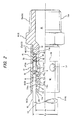
- the pipe end 54 as shown in Fig. 2 , reaches the base end 11a of the sleeve 11 through the correcting member 4.
- the O-ring 9 which has been elastically deformed and sunken into the ring-shaped groove 11c, is firmly in contact with the pipe inner surface 53 due to its elastic restoring force and seals the pipe 5 ( Fig. 2 ).
- the look ring 2 connects the pipe 5 to the joint main body 1 as an integral body.
- the obliquely cut pipe 5, as it is, can be inserted along the sleeve 11.
- the pipe end 54 gets over the lock ring 2.
- the pipe end face 55 is butted against the correcting member 4 and, after then, typically, as shown in Fig. 6 , the pipe 5 deforms elastically the elastically deformable correcting member 4 and is contacted with the elastically deformed correcting member 4 to thereby press against it.
- the correcting member 4 is elastically deformed, since the correcting member 4 is restricted by the cap nut 3, the outer diameter of the correcting member 4 is prevented from increasing.
- the sloped portion 41 which is upwardly situated in Fig. 6 and also from which the pipe end 54 projects up; firstly slides on the 0-ring 9 to crush it due to the elastic deformation, and then the sloped portion 41 and small diameter portion 42 get over the thus crushed O-ring 9. Following them, as shown in Fig. 7 , the sloped portion 41 situated downwardly of the pipe end face 55 slides over the O-ring 9 to crush it due to the elastic deformation, and then the sloped portion 41 and small diameter portion 42 respectively get over the thus crushed O-ring 9.
- the pipe 5 cut to a necessary length, as it is, can be inserted along the sleeve 11. Even if the inner surface of the pipe 5 is not chamfered, when the pipe 5 is inserted along the sleeve 11, the pipe end face 55 is contacted with the correcting member 4 to thereby produce a state where they seem to be connected together, whereby the sloped portion 41 of the correcting member 4 plays the role of the inner surface chamfering.
- the pipe end face 54 does not butt against the O-ring 9 directly, but the sloped portion 41 of the correcting member 4 butts against this O-ring 9.
- the lock ring 2 When trying to pull out the pipe 5, the lock ring 2 rises from the deep groove portion 11e 0 along the sloping groove portion 11e 1 to increase the diameter of the lock ring 2, and the pawl 22 bites into the pipe inner surface more deeply, whereby the one-touch connection of the pipe 5 to the pipe joint can be intensified further. That is, the one-touch connection of the pipe 5 to the pipe joint can be achieved smoothly and positively.
- the pipe joint according to this embodiment can solve the problems found in the conventional pipe joint.
- the connection of the pipe 5 having an obliquely cut end face 55 to the pipe joint has been conventionally difficult even when a chamfering tool is used.
- the correcting member 4 can follow the obliquely cut end face 55 of the pipe 5 due to its elastic deformation, whereby the pipe 5 can be integrally connected to the pipe joint with no difficulty, Specifically, when the obliquely cut pipe 5 is inserted along the sleeve 11 and is contacted with the correcting member 4, the pressure to insert the pipe 5 deforms elastically the correcting member 4 which is made of an elastic member.
- the end face 47 of the small diameter portion 42 of the correcting member 4 is elastically deformed according to the shape of the obliquely cut pipe end face 55.
- the correcting member 4 When the correcting member 4 receives the pressure from the obliquely cut pipe 5 fitted on the sleeve 11, for example, in Fig. 6 , firstly, the upwardly situated sloped portion 41 of the correcting member 4 presses and deforms the first O-ring 9, gets over the thus deformed O-ring 9, and moves toward the base end 11a of the sleeve 11. Following this, as shown in Fig. 7 , the downwardly situated sloped portion 41 presses and deforms the first O-ring 9, gets over the thus deformed O-ring 9, and moves toward the base end 11a of the sleeve 11.
- Similar operations to the first O-ring 9 are executed on the second O-ring 9 existing on the sleeve base end side and the lock ring 2 existing on the sleeve base end side, thereby being able to fit the obliquely cut pipe 5 with the outer surface of the sleeve 11 smoothly.
- the correcting member 4 is elastically deformed, since the hardness of the correcting member 4 is set equal to or higher than the hardness of the packing 9, the correcting member 4 is surely able to press and deform the O-ring 9.
- the cylindrical cap nut 3 prevents such cylinder outer peripheral surface from spreading.
- the correcting member 4 is allowed to move forward smoothly through a ring-shaped hole K which is formed by the cylindrical inner wall of the cap nut 3 and sleeve 11.
- the correcting member 4 further provides the following effects. That is, the cap nut 3 mounted on the joint main body 1 includes the cylindrical inner wall 31 the inner diameter of which is uniform at least from the lock ring 2 to be mounted on the sleeve distal end 11b side to the sleeve base end 11a.
- the cylindrical inner wall 31 lies close to or contacts the correcting member 4 at least in the range in which the correcting member 4 moves over a portion of the sleeve 11 where the packing 9 is fitted.
- the cap nut 3 includes the cylindrical inner wall 31 which can approach or touch the correcting member 4 in the moving range of the correcting member 4 on the sleeve 11. Therefore, since the correcting member 4, which has received the insertion pressure of the pipe 5 due to the insertion of the pipe 5 into the pipe joint, is prevented from spreading its diameter in the radially outward direction by the cylindrical inner wall 31 of the cap nut 3, simply by inserting the pipe 5 into the pipe joint, the correcting member 4 is forced to stay in the radially inward direction.
- the correcting member 4 tends to stay in the radially inward direction, not only the correcting member 4 can press the packing 9 and get over it, but also, without "setting the minimum inner diameter of the tapered part (corresponding to the sloped portion of the embodiment of the invention) equal to or smaller than the standard inner diameter of the pipe" as described in JP2003-314775A , the pipe following the correcting member 4 is allowed to accompany the correcting member 4 properly so that the pipe can be moved smoothly toward the sleeve base end.
- the correcting member 4 parses over the lock ring 2 disposed on the base end 11a side of the sleeve, since the correcting member 4 is an elastically deformable member made of rubber or the like and can be deformed by itself, the correcting member 4 can advantageously pass over the area of the lock ring 2 easily.
- the outer diameter of the lock ring 2 is set larger than the inner diameter d 42 of the small diameter portion 42, and the movement of the correcting member 4 to the distal end of the sleeve 11 is held by the lock ring 2 ( Fig. 3 ), it is possible to provide, as a pipe joint, an integrally assembled product in which the O-rings 9, lock ring 2, correcting member and cap nut 3 are assembled to the joint main body 1.
- the pipe joint is easy to keep and store. For example, it is possible to eliminate a situation in which one or more of the parts are missing, which occurs in a case where the respective parts are separately kept and stored. Since the correcting member 4 is prevented from dropping from the sleeve 11, the pipe joint is remarkably easy to handle. Also, according to the pipe joint shown in Figs. 1 to 7 and 10 , before it is used, when the correcting member 4 moves toward the base end 11a of the sleeve 11, the packing 9 butts against the correcting member 4 to thereby hold it, however, since no pressing load is applied to the packing 9 itself there is no possibility that the packing 9 can be distorted or permanently set. Therefore, when the pipe joint is in a non-use state, it can be advantageously stored for a long therm.
- non-conductive spacer made of rubber or the like between them to avoid the mutual contact between them.
- the correcting member 4 is made of non-conductive rubber, thermoplastic elastomer or the like which is excellent in the electric characteristics, the cost for preparing a spacer separately and the operation to mount the spacer can be saved, which is another advantage of the invention. In this manner, the pipe joint provides many excellent effects.
- the present invention is not limited to the embodiments described above, and various changes and modifications can be made therein in accordance with purposes and uses thereof without departing from the scope of the invention.
- the shapes, sizes and number of the joint main body 1, lock ring 2, cap nut 3, correcting member 4, packing 9 and the like can be properly chosen according to the uses of the invention.
- the connecting portion 15 thereof is composed of a nut member 16.
- This nut member 16 may be configured such that it can be removed from the main portion 10 and, in use, the inner flange 16a of the nut member 16 is secured to the outer flange 10a of the main portion 10.
- the female screw portion 16b of the nut member 16 is formed as a threadedly engageable portion and is used as the connecting portion 15 which can be connected to the other joint
Landscapes
- Engineering & Computer Science (AREA)
- General Engineering & Computer Science (AREA)
- Mechanical Engineering (AREA)
- Quick-Acting Or Multi-Walled Pipe Joints (AREA)
- Joints With Pressure Members (AREA)
Applications Claiming Priority (1)
| Application Number | Priority Date | Filing Date | Title |
|---|---|---|---|
| JP2008276183A JP5357499B2 (ja) | 2008-10-27 | 2008-10-27 | パイプ継手 |
Publications (3)
| Publication Number | Publication Date |
|---|---|
| EP2180224A2 true EP2180224A2 (de) | 2010-04-28 |
| EP2180224A3 EP2180224A3 (de) | 2013-03-06 |
| EP2180224B1 EP2180224B1 (de) | 2014-03-26 |
Family
ID=41559428
Family Applications (1)
| Application Number | Title | Priority Date | Filing Date |
|---|---|---|---|
| EP09174147.0A Not-in-force EP2180224B1 (de) | 2008-10-27 | 2009-10-27 | Rohrverbindung |
Country Status (2)
| Country | Link |
|---|---|
| EP (1) | EP2180224B1 (de) |
| JP (1) | JP5357499B2 (de) |
Cited By (3)
| Publication number | Priority date | Publication date | Assignee | Title |
|---|---|---|---|---|
| EP2423554A1 (de) * | 2010-08-31 | 2012-02-29 | Geberit International AG | Fitting für Wasserrohre |
| JP2014196827A (ja) * | 2014-06-19 | 2014-10-16 | 株式会社キッツ | 管継手 |
| WO2019048460A1 (de) * | 2017-09-06 | 2019-03-14 | Fränkische Rohrwerke Gebr. Kirchner Gmbh & Co. Kg | Verbindungsanordnung für rohre |
Families Citing this family (7)
| Publication number | Priority date | Publication date | Assignee | Title |
|---|---|---|---|---|
| JP5496790B2 (ja) * | 2010-06-29 | 2014-05-21 | 株式会社オンダ製作所 | 継手 |
| JP5567430B2 (ja) * | 2010-08-31 | 2014-08-06 | 株式会社キッツ | 管継手 |
| JP5812637B2 (ja) * | 2011-03-22 | 2015-11-17 | 株式会社キッツ | 管継手 |
| US11048994B2 (en) | 2017-08-11 | 2021-06-29 | Norma U.S. Holding Llc | Fluid line connector and assembly with securement detection |
| US11199282B2 (en) | 2017-08-11 | 2021-12-14 | Norma U.S. Holding Llc | Fluid line connector and assembly with securement detection |
| US11306857B2 (en) | 2017-08-11 | 2022-04-19 | Norma U.S. Holding Llc | Fluid line connector and assembly with securement detection |
| JP7102505B2 (ja) | 2017-08-11 | 2022-07-19 | ノーマ・ユー・エス・ホールディング・リミテッド・ライアビリティ・カンパニー | 固定検出を有する流体ラインコネクタおよびアセンブリ |
Citations (2)
| Publication number | Priority date | Publication date | Assignee | Title |
|---|---|---|---|---|
| DE9308181U1 (de) * | 1993-01-04 | 1994-05-05 | Schaefer Stettiner Schrauben | Anschlußarmatur für Rohre |
| JP2004232692A (ja) * | 2003-01-29 | 2004-08-19 | Jfe Pipe Fitting Mfg Co Ltd | 差込み式管継手 |
Family Cites Families (3)
| Publication number | Priority date | Publication date | Assignee | Title |
|---|---|---|---|---|
| JP4474044B2 (ja) * | 2000-12-06 | 2010-06-02 | Jfe継手株式会社 | 差込み式管継手、及び差込み式管継手への管差込み方法 |
| JP4890130B2 (ja) * | 2005-12-28 | 2012-03-07 | 株式会社キッツ | 樹脂管用ワンタッチ継手 |
| JP2008025819A (ja) * | 2006-07-24 | 2008-02-07 | Sanyo Seisakusho:Kk | 継手 |
-
2008
- 2008-10-27 JP JP2008276183A patent/JP5357499B2/ja active Active
-
2009
- 2009-10-27 EP EP09174147.0A patent/EP2180224B1/de not_active Not-in-force
Patent Citations (2)
| Publication number | Priority date | Publication date | Assignee | Title |
|---|---|---|---|---|
| DE9308181U1 (de) * | 1993-01-04 | 1994-05-05 | Schaefer Stettiner Schrauben | Anschlußarmatur für Rohre |
| JP2004232692A (ja) * | 2003-01-29 | 2004-08-19 | Jfe Pipe Fitting Mfg Co Ltd | 差込み式管継手 |
Cited By (3)
| Publication number | Priority date | Publication date | Assignee | Title |
|---|---|---|---|---|
| EP2423554A1 (de) * | 2010-08-31 | 2012-02-29 | Geberit International AG | Fitting für Wasserrohre |
| JP2014196827A (ja) * | 2014-06-19 | 2014-10-16 | 株式会社キッツ | 管継手 |
| WO2019048460A1 (de) * | 2017-09-06 | 2019-03-14 | Fränkische Rohrwerke Gebr. Kirchner Gmbh & Co. Kg | Verbindungsanordnung für rohre |
Also Published As
| Publication number | Publication date |
|---|---|
| EP2180224A3 (de) | 2013-03-06 |
| JP2010101477A (ja) | 2010-05-06 |
| JP5357499B2 (ja) | 2013-12-04 |
| EP2180224B1 (de) | 2014-03-26 |
Similar Documents
| Publication | Publication Date | Title |
|---|---|---|
| EP2180224B1 (de) | Rohrverbindung | |
| EP2503207B1 (de) | Rohrverbindung | |
| JP4174738B2 (ja) | ホース継手 | |
| EP1870623B1 (de) | Aus einem steck- und aufnahmeglied bestehende anordnung | |
| JP2008291886A (ja) | 管継手 | |
| US6843507B2 (en) | Tube joint | |
| US11384875B2 (en) | Pipe joint, separation prevention member, and method of connecting pipes | |
| JP4762704B2 (ja) | 継手 | |
| WO2008118944A2 (en) | Sealing fitting for stainless steel tubing | |
| KR19990062400A (ko) | 신축형 로드 안테나 및 그 제조 방법 | |
| JP4947706B2 (ja) | 管継手 | |
| EP0003142B1 (de) | Endgarnitur für Schläuche und Verfahren zum Zusammenfügen | |
| JP4962849B2 (ja) | 管継手 | |
| JP5111212B2 (ja) | 通水管の接続具 | |
| JP2010101475A (ja) | パイプ継手 | |
| JP2011069484A (ja) | ホース継手 | |
| JP3030497B2 (ja) | 管接続装置 | |
| JP4938470B2 (ja) | 通水管の接続端部、通水管接続用の係合体、通水管接続用のコア部材、通水管体、通水管の接続構造、通水管装置、通水管の保護キャップ、および通水管の接続端部形成工具 | |
| JP3219074B2 (ja) | ホース継手 | |
| JP6190605B2 (ja) | 管継手 | |
| GB2471502A (en) | A universal compression-type pipe coupling | |
| JP5778386B2 (ja) | 管継手用ロックリング、管継手、及び、管継手用ロックリングの製造方法 | |
| JP5098101B2 (ja) | 管継手 | |
| JP4428621B2 (ja) | インコア | |
| JP3378089B2 (ja) | 管継手 |
Legal Events
| Date | Code | Title | Description |
|---|---|---|---|
| PUAI | Public reference made under article 153(3) epc to a published international application that has entered the european phase |
Free format text: ORIGINAL CODE: 0009012 |
|
| AK | Designated contracting states |
Kind code of ref document: A2 Designated state(s): AT BE BG CH CY CZ DE DK EE ES FI FR GB GR HR HU IE IS IT LI LT LU LV MC MK MT NL NO PL PT RO SE SI SK SM TR |
|
| PUAL | Search report despatched |
Free format text: ORIGINAL CODE: 0009013 |
|
| AK | Designated contracting states |
Kind code of ref document: A3 Designated state(s): AT BE BG CH CY CZ DE DK EE ES FI FR GB GR HR HU IE IS IT LI LT LU LV MC MK MT NL NO PL PT RO SE SI SK SM TR |
|
| RIC1 | Information provided on ipc code assigned before grant |
Ipc: F16L 37/092 20060101ALI20130130BHEP Ipc: F16L 37/088 20060101AFI20130130BHEP |
|
| 17P | Request for examination filed |
Effective date: 20130829 |
|
| RBV | Designated contracting states (corrected) |
Designated state(s): AT BE BG CH CY CZ DE DK EE ES FI FR GB GR HR HU IE IS IT LI LT LU LV MC MK MT NL NO PL PT RO SE SI SK SM TR |
|
| GRAP | Despatch of communication of intention to grant a patent |
Free format text: ORIGINAL CODE: EPIDOSNIGR1 |
|
| INTG | Intention to grant announced |
Effective date: 20131028 |
|
| RAP1 | Party data changed (applicant data changed or rights of an application transferred) |
Owner name: INOAC HOUSING & CONSTRUCTION MATERIALS CO., LTD |
|
| RIN1 | Information on inventor provided before grant (corrected) |
Inventor name: IKEDA, KOJI |
|
| GRAS | Grant fee paid |
Free format text: ORIGINAL CODE: EPIDOSNIGR3 |
|
| GRAA | (expected) grant |
Free format text: ORIGINAL CODE: 0009210 |
|
| AK | Designated contracting states |
Kind code of ref document: B1 Designated state(s): AT BE BG CH CY CZ DE DK EE ES FI FR GB GR HR HU IE IS IT LI LT LU LV MC MK MT NL NO PL PT RO SE SI SK SM TR |
|
| REG | Reference to a national code |
Ref country code: GB Ref legal event code: FG4D |
|
| REG | Reference to a national code |
Ref country code: CH Ref legal event code: EP |
|
| REG | Reference to a national code |
Ref country code: AT Ref legal event code: REF Ref document number: 659188 Country of ref document: AT Kind code of ref document: T Effective date: 20140415 |
|
| REG | Reference to a national code |
Ref country code: IE Ref legal event code: FG4D |
|
| REG | Reference to a national code |
Ref country code: DE Ref legal event code: R096 Ref document number: 602009022728 Country of ref document: DE Effective date: 20140508 |
|
| PG25 | Lapsed in a contracting state [announced via postgrant information from national office to epo] |
Ref country code: LT Free format text: LAPSE BECAUSE OF FAILURE TO SUBMIT A TRANSLATION OF THE DESCRIPTION OR TO PAY THE FEE WITHIN THE PRESCRIBED TIME-LIMIT Effective date: 20140326 Ref country code: NO Free format text: LAPSE BECAUSE OF FAILURE TO SUBMIT A TRANSLATION OF THE DESCRIPTION OR TO PAY THE FEE WITHIN THE PRESCRIBED TIME-LIMIT Effective date: 20140626 |
|
| REG | Reference to a national code |
Ref country code: AT Ref legal event code: MK05 Ref document number: 659188 Country of ref document: AT Kind code of ref document: T Effective date: 20140326 |
|
| REG | Reference to a national code |
Ref country code: NL Ref legal event code: VDEP Effective date: 20140326 |
|
| REG | Reference to a national code |
Ref country code: LT Ref legal event code: MG4D |
|
| PG25 | Lapsed in a contracting state [announced via postgrant information from national office to epo] |
Ref country code: FI Free format text: LAPSE BECAUSE OF FAILURE TO SUBMIT A TRANSLATION OF THE DESCRIPTION OR TO PAY THE FEE WITHIN THE PRESCRIBED TIME-LIMIT Effective date: 20140326 Ref country code: SE Free format text: LAPSE BECAUSE OF FAILURE TO SUBMIT A TRANSLATION OF THE DESCRIPTION OR TO PAY THE FEE WITHIN THE PRESCRIBED TIME-LIMIT Effective date: 20140326 |
|
| PG25 | Lapsed in a contracting state [announced via postgrant information from national office to epo] |
Ref country code: LV Free format text: LAPSE BECAUSE OF FAILURE TO SUBMIT A TRANSLATION OF THE DESCRIPTION OR TO PAY THE FEE WITHIN THE PRESCRIBED TIME-LIMIT Effective date: 20140326 Ref country code: HR Free format text: LAPSE BECAUSE OF FAILURE TO SUBMIT A TRANSLATION OF THE DESCRIPTION OR TO PAY THE FEE WITHIN THE PRESCRIBED TIME-LIMIT Effective date: 20140326 |
|
| PG25 | Lapsed in a contracting state [announced via postgrant information from national office to epo] |
Ref country code: CZ Free format text: LAPSE BECAUSE OF FAILURE TO SUBMIT A TRANSLATION OF THE DESCRIPTION OR TO PAY THE FEE WITHIN THE PRESCRIBED TIME-LIMIT Effective date: 20140326 Ref country code: RO Free format text: LAPSE BECAUSE OF FAILURE TO SUBMIT A TRANSLATION OF THE DESCRIPTION OR TO PAY THE FEE WITHIN THE PRESCRIBED TIME-LIMIT Effective date: 20140326 Ref country code: BG Free format text: LAPSE BECAUSE OF FAILURE TO SUBMIT A TRANSLATION OF THE DESCRIPTION OR TO PAY THE FEE WITHIN THE PRESCRIBED TIME-LIMIT Effective date: 20140626 Ref country code: NL Free format text: LAPSE BECAUSE OF FAILURE TO SUBMIT A TRANSLATION OF THE DESCRIPTION OR TO PAY THE FEE WITHIN THE PRESCRIBED TIME-LIMIT Effective date: 20140326 Ref country code: EE Free format text: LAPSE BECAUSE OF FAILURE TO SUBMIT A TRANSLATION OF THE DESCRIPTION OR TO PAY THE FEE WITHIN THE PRESCRIBED TIME-LIMIT Effective date: 20140326 Ref country code: CY Free format text: LAPSE BECAUSE OF FAILURE TO SUBMIT A TRANSLATION OF THE DESCRIPTION OR TO PAY THE FEE WITHIN THE PRESCRIBED TIME-LIMIT Effective date: 20140326 Ref country code: BE Free format text: LAPSE BECAUSE OF FAILURE TO SUBMIT A TRANSLATION OF THE DESCRIPTION OR TO PAY THE FEE WITHIN THE PRESCRIBED TIME-LIMIT Effective date: 20140326 Ref country code: IS Free format text: LAPSE BECAUSE OF FAILURE TO SUBMIT A TRANSLATION OF THE DESCRIPTION OR TO PAY THE FEE WITHIN THE PRESCRIBED TIME-LIMIT Effective date: 20140726 |
|
| PG25 | Lapsed in a contracting state [announced via postgrant information from national office to epo] |
Ref country code: AT Free format text: LAPSE BECAUSE OF FAILURE TO SUBMIT A TRANSLATION OF THE DESCRIPTION OR TO PAY THE FEE WITHIN THE PRESCRIBED TIME-LIMIT Effective date: 20140326 Ref country code: PL Free format text: LAPSE BECAUSE OF FAILURE TO SUBMIT A TRANSLATION OF THE DESCRIPTION OR TO PAY THE FEE WITHIN THE PRESCRIBED TIME-LIMIT Effective date: 20140326 Ref country code: SK Free format text: LAPSE BECAUSE OF FAILURE TO SUBMIT A TRANSLATION OF THE DESCRIPTION OR TO PAY THE FEE WITHIN THE PRESCRIBED TIME-LIMIT Effective date: 20140326 Ref country code: ES Free format text: LAPSE BECAUSE OF FAILURE TO SUBMIT A TRANSLATION OF THE DESCRIPTION OR TO PAY THE FEE WITHIN THE PRESCRIBED TIME-LIMIT Effective date: 20140326 |
|
| PG25 | Lapsed in a contracting state [announced via postgrant information from national office to epo] |
Ref country code: PT Free format text: LAPSE BECAUSE OF FAILURE TO SUBMIT A TRANSLATION OF THE DESCRIPTION OR TO PAY THE FEE WITHIN THE PRESCRIBED TIME-LIMIT Effective date: 20140728 |
|
| REG | Reference to a national code |
Ref country code: DE Ref legal event code: R097 Ref document number: 602009022728 Country of ref document: DE |
|
| PG25 | Lapsed in a contracting state [announced via postgrant information from national office to epo] |
Ref country code: DK Free format text: LAPSE BECAUSE OF FAILURE TO SUBMIT A TRANSLATION OF THE DESCRIPTION OR TO PAY THE FEE WITHIN THE PRESCRIBED TIME-LIMIT Effective date: 20140326 |
|
| PLBE | No opposition filed within time limit |
Free format text: ORIGINAL CODE: 0009261 |
|
| STAA | Information on the status of an ep patent application or granted ep patent |
Free format text: STATUS: NO OPPOSITION FILED WITHIN TIME LIMIT |
|
| 26N | No opposition filed |
Effective date: 20150106 |
|
| PG25 | Lapsed in a contracting state [announced via postgrant information from national office to epo] |
Ref country code: IT Free format text: LAPSE BECAUSE OF FAILURE TO SUBMIT A TRANSLATION OF THE DESCRIPTION OR TO PAY THE FEE WITHIN THE PRESCRIBED TIME-LIMIT Effective date: 20140326 |
|
| REG | Reference to a national code |
Ref country code: DE Ref legal event code: R097 Ref document number: 602009022728 Country of ref document: DE Effective date: 20150106 |
|
| PG25 | Lapsed in a contracting state [announced via postgrant information from national office to epo] |
Ref country code: LU Free format text: LAPSE BECAUSE OF FAILURE TO SUBMIT A TRANSLATION OF THE DESCRIPTION OR TO PAY THE FEE WITHIN THE PRESCRIBED TIME-LIMIT Effective date: 20141027 Ref country code: MC Free format text: LAPSE BECAUSE OF FAILURE TO SUBMIT A TRANSLATION OF THE DESCRIPTION OR TO PAY THE FEE WITHIN THE PRESCRIBED TIME-LIMIT Effective date: 20140326 |
|
| REG | Reference to a national code |
Ref country code: CH Ref legal event code: PL |
|
| REG | Reference to a national code |
Ref country code: IE Ref legal event code: MM4A |
|
| PG25 | Lapsed in a contracting state [announced via postgrant information from national office to epo] |
Ref country code: LI Free format text: LAPSE BECAUSE OF NON-PAYMENT OF DUE FEES Effective date: 20141031 Ref country code: SI Free format text: LAPSE BECAUSE OF FAILURE TO SUBMIT A TRANSLATION OF THE DESCRIPTION OR TO PAY THE FEE WITHIN THE PRESCRIBED TIME-LIMIT Effective date: 20140326 Ref country code: CH Free format text: LAPSE BECAUSE OF NON-PAYMENT OF DUE FEES Effective date: 20141031 |
|
| REG | Reference to a national code |
Ref country code: FR Ref legal event code: PLFP Year of fee payment: 7 |
|
| PG25 | Lapsed in a contracting state [announced via postgrant information from national office to epo] |
Ref country code: IE Free format text: LAPSE BECAUSE OF NON-PAYMENT OF DUE FEES Effective date: 20141027 |
|
| PGFP | Annual fee paid to national office [announced via postgrant information from national office to epo] |
Ref country code: FR Payment date: 20150908 Year of fee payment: 7 |
|
| PGFP | Annual fee paid to national office [announced via postgrant information from national office to epo] |
Ref country code: GB Payment date: 20151021 Year of fee payment: 7 Ref country code: DE Payment date: 20151020 Year of fee payment: 7 |
|
| PG25 | Lapsed in a contracting state [announced via postgrant information from national office to epo] |
Ref country code: SM Free format text: LAPSE BECAUSE OF FAILURE TO SUBMIT A TRANSLATION OF THE DESCRIPTION OR TO PAY THE FEE WITHIN THE PRESCRIBED TIME-LIMIT Effective date: 20140326 |
|
| PG25 | Lapsed in a contracting state [announced via postgrant information from national office to epo] |
Ref country code: GR Free format text: LAPSE BECAUSE OF FAILURE TO SUBMIT A TRANSLATION OF THE DESCRIPTION OR TO PAY THE FEE WITHIN THE PRESCRIBED TIME-LIMIT Effective date: 20140627 |
|
| PG25 | Lapsed in a contracting state [announced via postgrant information from national office to epo] |
Ref country code: HU Free format text: LAPSE BECAUSE OF FAILURE TO SUBMIT A TRANSLATION OF THE DESCRIPTION OR TO PAY THE FEE WITHIN THE PRESCRIBED TIME-LIMIT; INVALID AB INITIO Effective date: 20091027 Ref country code: MT Free format text: LAPSE BECAUSE OF FAILURE TO SUBMIT A TRANSLATION OF THE DESCRIPTION OR TO PAY THE FEE WITHIN THE PRESCRIBED TIME-LIMIT Effective date: 20140326 Ref country code: TR Free format text: LAPSE BECAUSE OF FAILURE TO SUBMIT A TRANSLATION OF THE DESCRIPTION OR TO PAY THE FEE WITHIN THE PRESCRIBED TIME-LIMIT Effective date: 20140326 |
|
| REG | Reference to a national code |
Ref country code: DE Ref legal event code: R119 Ref document number: 602009022728 Country of ref document: DE |
|
| GBPC | Gb: european patent ceased through non-payment of renewal fee |
Effective date: 20161027 |
|
| REG | Reference to a national code |
Ref country code: FR Ref legal event code: ST Effective date: 20170630 |
|
| PG25 | Lapsed in a contracting state [announced via postgrant information from national office to epo] |
Ref country code: DE Free format text: LAPSE BECAUSE OF NON-PAYMENT OF DUE FEES Effective date: 20170503 Ref country code: FR Free format text: LAPSE BECAUSE OF NON-PAYMENT OF DUE FEES Effective date: 20161102 Ref country code: GB Free format text: LAPSE BECAUSE OF NON-PAYMENT OF DUE FEES Effective date: 20161027 |
|
| PG25 | Lapsed in a contracting state [announced via postgrant information from national office to epo] |
Ref country code: MK Free format text: LAPSE BECAUSE OF FAILURE TO SUBMIT A TRANSLATION OF THE DESCRIPTION OR TO PAY THE FEE WITHIN THE PRESCRIBED TIME-LIMIT Effective date: 20140326 |