EP2179985B1 - Mit strömungsleitungen ausgestatteter jetreaktor, verfahren zur herstellung von isocyanaten mittels eines solchen reaktors - Google Patents
Mit strömungsleitungen ausgestatteter jetreaktor, verfahren zur herstellung von isocyanaten mittels eines solchen reaktors Download PDFInfo
- Publication number
- EP2179985B1 EP2179985B1 EP07800746.5A EP07800746A EP2179985B1 EP 2179985 B1 EP2179985 B1 EP 2179985B1 EP 07800746 A EP07800746 A EP 07800746A EP 2179985 B1 EP2179985 B1 EP 2179985B1
- Authority
- EP
- European Patent Office
- Prior art keywords
- feed tube
- jet
- internal feed
- flow
- flow ducts
- Prior art date
- Legal status (The legal status is an assumption and is not a legal conclusion. Google has not performed a legal analysis and makes no representation as to the accuracy of the status listed.)
- Active
Links
- 239000012948 isocyanate Substances 0.000 title claims description 14
- 150000002513 isocyanates Chemical class 0.000 title claims description 10
- 238000004519 manufacturing process Methods 0.000 title description 6
- 239000007789 gas Substances 0.000 claims description 50
- 238000006243 chemical reaction Methods 0.000 claims description 45
- 150000001412 amines Chemical class 0.000 claims description 40
- YGYAWVDWMABLBF-UHFFFAOYSA-N Phosgene Chemical compound ClC(Cl)=O YGYAWVDWMABLBF-UHFFFAOYSA-N 0.000 claims description 38
- 238000010521 absorption reaction Methods 0.000 claims description 37
- 239000000203 mixture Substances 0.000 claims description 29
- IJGRMHOSHXDMSA-UHFFFAOYSA-N Atomic nitrogen Chemical compound N#N IJGRMHOSHXDMSA-UHFFFAOYSA-N 0.000 claims description 28
- 239000006096 absorbing agent Substances 0.000 claims description 24
- 238000000034 method Methods 0.000 claims description 21
- RFFLAFLAYFXFSW-UHFFFAOYSA-N 1,2-dichlorobenzene Chemical compound ClC1=CC=CC=C1Cl RFFLAFLAYFXFSW-UHFFFAOYSA-N 0.000 claims description 18
- NAQMVNRVTILPCV-UHFFFAOYSA-N hexane-1,6-diamine Chemical compound NCCCCCCN NAQMVNRVTILPCV-UHFFFAOYSA-N 0.000 claims description 18
- 239000002904 solvent Substances 0.000 claims description 15
- YXFVVABEGXRONW-UHFFFAOYSA-N Toluene Natural products CC1=CC=CC=C1 YXFVVABEGXRONW-UHFFFAOYSA-N 0.000 claims description 14
- 229910052757 nitrogen Inorganic materials 0.000 claims description 14
- RRAMGCGOFNQTLD-UHFFFAOYSA-N hexamethylene diisocyanate Chemical compound O=C=NCCCCCCN=C=O RRAMGCGOFNQTLD-UHFFFAOYSA-N 0.000 claims description 12
- MVPPADPHJFYWMZ-UHFFFAOYSA-N chlorobenzene Chemical compound ClC1=CC=CC=C1 MVPPADPHJFYWMZ-UHFFFAOYSA-N 0.000 claims description 10
- RNLHGQLZWXBQNY-UHFFFAOYSA-N 3-(aminomethyl)-3,5,5-trimethylcyclohexan-1-amine Chemical compound CC1(C)CC(N)CC(C)(CN)C1 RNLHGQLZWXBQNY-UHFFFAOYSA-N 0.000 claims description 9
- 238000012856 packing Methods 0.000 claims description 9
- 125000001931 aliphatic group Chemical group 0.000 claims description 8
- 239000011261 inert gas Substances 0.000 claims description 8
- 239000012442 inert solvent Substances 0.000 claims description 8
- 125000002723 alicyclic group Chemical group 0.000 claims description 7
- XKRFYHLGVUSROY-UHFFFAOYSA-N Argon Chemical compound [Ar] XKRFYHLGVUSROY-UHFFFAOYSA-N 0.000 claims description 6
- -1 aromatic isocyanates Chemical class 0.000 claims description 6
- NNBZCPXTIHJBJL-UHFFFAOYSA-N decalin Chemical compound C1CCCC2CCCCC21 NNBZCPXTIHJBJL-UHFFFAOYSA-N 0.000 claims description 6
- HMJBXEZHJUYJQY-UHFFFAOYSA-N 4-(aminomethyl)octane-1,8-diamine Chemical compound NCCCCC(CN)CCCN HMJBXEZHJUYJQY-UHFFFAOYSA-N 0.000 claims description 5
- DZIHTWJGPDVSGE-UHFFFAOYSA-N 4-[(4-aminocyclohexyl)methyl]cyclohexan-1-amine Chemical compound C1CC(N)CCC1CC1CCC(N)CC1 DZIHTWJGPDVSGE-UHFFFAOYSA-N 0.000 claims description 5
- CTQNGGLPUBDAKN-UHFFFAOYSA-N O-Xylene Chemical compound CC1=CC=CC=C1C CTQNGGLPUBDAKN-UHFFFAOYSA-N 0.000 claims description 5
- 239000008096 xylene Substances 0.000 claims description 5
- 239000007788 liquid Substances 0.000 claims description 4
- KIDHWZJUCRJVML-UHFFFAOYSA-N putrescine Chemical compound NCCCCN KIDHWZJUCRJVML-UHFFFAOYSA-N 0.000 claims description 4
- 229910052786 argon Inorganic materials 0.000 claims description 3
- 125000004432 carbon atom Chemical group C* 0.000 claims description 3
- NIMLQBUJDJZYEJ-UHFFFAOYSA-N isophorone diisocyanate Chemical compound CC1(C)CC(N=C=O)CC(C)(CN=C=O)C1 NIMLQBUJDJZYEJ-UHFFFAOYSA-N 0.000 claims description 3
- DVKJHBMWWAPEIU-UHFFFAOYSA-N toluene 2,4-diisocyanate Chemical compound CC1=CC=C(N=C=O)C=C1N=C=O DVKJHBMWWAPEIU-UHFFFAOYSA-N 0.000 claims description 3
- PXXNTAGJWPJAGM-UHFFFAOYSA-N vertaline Natural products C1C2C=3C=C(OC)C(OC)=CC=3OC(C=C3)=CC=C3CCC(=O)OC1CC1N2CCCC1 PXXNTAGJWPJAGM-UHFFFAOYSA-N 0.000 claims description 3
- OVBFMUAFNIIQAL-UHFFFAOYSA-N 1,4-diisocyanatobutane Chemical compound O=C=NCCCCN=C=O OVBFMUAFNIIQAL-UHFFFAOYSA-N 0.000 claims description 2
- CDMDQYCEEKCBGR-UHFFFAOYSA-N 1,4-diisocyanatocyclohexane Chemical compound O=C=NC1CCC(N=C=O)CC1 CDMDQYCEEKCBGR-UHFFFAOYSA-N 0.000 claims description 2
- 229940008841 1,6-hexamethylene diisocyanate Drugs 0.000 claims description 2
- ZHESOIPTRUDICE-UHFFFAOYSA-N CCCCCCCCC.N=C=O.N=C=O.N=C=O Chemical compound CCCCCCCCC.N=C=O.N=C=O.N=C=O ZHESOIPTRUDICE-UHFFFAOYSA-N 0.000 claims description 2
- 239000005058 Isophorone diisocyanate Substances 0.000 claims description 2
- 239000005700 Putrescine Substances 0.000 claims description 2
- 125000002029 aromatic hydrocarbon group Chemical group 0.000 claims description 2
- VKIRRGRTJUUZHS-UHFFFAOYSA-N cyclohexane-1,4-diamine Chemical compound NC1CCC(N)CC1 VKIRRGRTJUUZHS-UHFFFAOYSA-N 0.000 claims description 2
- KORSJDCBLAPZEQ-UHFFFAOYSA-N dicyclohexylmethane-4,4'-diisocyanate Chemical compound C1CC(N=C=O)CCC1CC1CCC(N=C=O)CC1 KORSJDCBLAPZEQ-UHFFFAOYSA-N 0.000 claims description 2
- 230000003068 static effect Effects 0.000 claims description 2
- 239000000126 substance Substances 0.000 claims 2
- VOZKAJLKRJDJLL-UHFFFAOYSA-N 2,4-diaminotoluene Chemical compound CC1=CC=C(N)C=C1N VOZKAJLKRJDJLL-UHFFFAOYSA-N 0.000 claims 1
- 125000003944 tolyl group Chemical group 0.000 claims 1
- 230000007704 transition Effects 0.000 claims 1
- 238000002156 mixing Methods 0.000 description 18
- 238000010791 quenching Methods 0.000 description 11
- 230000000171 quenching effect Effects 0.000 description 10
- 239000000376 reactant Substances 0.000 description 8
- 230000000694 effects Effects 0.000 description 7
- 239000006227 byproduct Substances 0.000 description 6
- 239000000047 product Substances 0.000 description 6
- 125000003277 amino group Chemical group 0.000 description 4
- 239000007795 chemical reaction product Substances 0.000 description 4
- VEXZGXHMUGYJMC-UHFFFAOYSA-N Hydrochloric acid Chemical compound Cl VEXZGXHMUGYJMC-UHFFFAOYSA-N 0.000 description 3
- 238000000354 decomposition reaction Methods 0.000 description 3
- 229910000831 Steel Inorganic materials 0.000 description 2
- 238000003556 assay Methods 0.000 description 2
- 230000000052 comparative effect Effects 0.000 description 2
- 239000002826 coolant Substances 0.000 description 2
- 150000004985 diamines Chemical class 0.000 description 2
- 125000005842 heteroatom Chemical group 0.000 description 2
- 238000010606 normalization Methods 0.000 description 2
- 238000002360 preparation method Methods 0.000 description 2
- 238000000746 purification Methods 0.000 description 2
- 239000007787 solid Substances 0.000 description 2
- 239000010959 steel Substances 0.000 description 2
- 230000001502 supplementing effect Effects 0.000 description 2
- XLYOFNOQVPJJNP-UHFFFAOYSA-N water Substances O XLYOFNOQVPJJNP-UHFFFAOYSA-N 0.000 description 2
- GEYOCULIXLDCMW-UHFFFAOYSA-N 1,2-phenylenediamine Chemical compound NC1=CC=CC=C1N GEYOCULIXLDCMW-UHFFFAOYSA-N 0.000 description 1
- VZSRBBMJRBPUNF-UHFFFAOYSA-N 2-(2,3-dihydro-1H-inden-2-ylamino)-N-[3-oxo-3-(2,4,6,7-tetrahydrotriazolo[4,5-c]pyridin-5-yl)propyl]pyrimidine-5-carboxamide Chemical compound C1C(CC2=CC=CC=C12)NC1=NC=C(C=N1)C(=O)NCCC(N1CC2=C(CC1)NN=N2)=O VZSRBBMJRBPUNF-UHFFFAOYSA-N 0.000 description 1
- YBRVSVVVWCFQMG-UHFFFAOYSA-N 4,4'-diaminodiphenylmethane Chemical compound C1=CC(N)=CC=C1CC1=CC=C(N)C=C1 YBRVSVVVWCFQMG-UHFFFAOYSA-N 0.000 description 1
- 239000005057 Hexamethylene diisocyanate Substances 0.000 description 1
- AFCARXCZXQIEQB-UHFFFAOYSA-N N-[3-oxo-3-(2,4,6,7-tetrahydrotriazolo[4,5-c]pyridin-5-yl)propyl]-2-[[3-(trifluoromethoxy)phenyl]methylamino]pyrimidine-5-carboxamide Chemical compound O=C(CCNC(=O)C=1C=NC(=NC=1)NCC1=CC(=CC=C1)OC(F)(F)F)N1CC2=C(CC1)NN=N2 AFCARXCZXQIEQB-UHFFFAOYSA-N 0.000 description 1
- 239000000956 alloy Substances 0.000 description 1
- 229910045601 alloy Inorganic materials 0.000 description 1
- 238000013459 approach Methods 0.000 description 1
- 150000004982 aromatic amines Chemical class 0.000 description 1
- 125000003118 aryl group Chemical group 0.000 description 1
- 238000009835 boiling Methods 0.000 description 1
- 235000013877 carbamide Nutrition 0.000 description 1
- 150000001875 compounds Chemical class 0.000 description 1
- 238000009833 condensation Methods 0.000 description 1
- 230000005494 condensation Effects 0.000 description 1
- 238000001816 cooling Methods 0.000 description 1
- 238000013461 design Methods 0.000 description 1
- 239000012530 fluid Substances 0.000 description 1
- 238000010574 gas phase reaction Methods 0.000 description 1
- 239000008246 gaseous mixture Substances 0.000 description 1
- 239000011521 glass Substances 0.000 description 1
- 125000001183 hydrocarbyl group Chemical group 0.000 description 1
- 230000007774 longterm Effects 0.000 description 1
- NTNWKDHZTDQSST-UHFFFAOYSA-N naphthalene-1,2-diamine Chemical compound C1=CC=CC2=C(N)C(N)=CC=C21 NTNWKDHZTDQSST-UHFFFAOYSA-N 0.000 description 1
- YNOGYQAEJGADFJ-UHFFFAOYSA-N oxolan-2-ylmethanamine Chemical compound NCC1CCCO1 YNOGYQAEJGADFJ-UHFFFAOYSA-N 0.000 description 1
- 229910052760 oxygen Inorganic materials 0.000 description 1
- 229920000642 polymer Polymers 0.000 description 1
- 150000003141 primary amines Chemical class 0.000 description 1
- 239000012495 reaction gas Substances 0.000 description 1
- 229910052717 sulfur Inorganic materials 0.000 description 1
- 150000004998 toluenediamines Chemical class 0.000 description 1
- 238000012546 transfer Methods 0.000 description 1
- 150000003672 ureas Chemical class 0.000 description 1
- 238000005406 washing Methods 0.000 description 1
Images

Classifications
-
- B—PERFORMING OPERATIONS; TRANSPORTING
- B01—PHYSICAL OR CHEMICAL PROCESSES OR APPARATUS IN GENERAL
- B01J—CHEMICAL OR PHYSICAL PROCESSES, e.g. CATALYSIS OR COLLOID CHEMISTRY; THEIR RELEVANT APPARATUS
- B01J19/00—Chemical, physical or physico-chemical processes in general; Their relevant apparatus
- B01J19/26—Nozzle-type reactors, i.e. the distribution of the initial reactants within the reactor is effected by their introduction or injection through nozzles
-
- B—PERFORMING OPERATIONS; TRANSPORTING
- B01—PHYSICAL OR CHEMICAL PROCESSES OR APPARATUS IN GENERAL
- B01F—MIXING, e.g. DISSOLVING, EMULSIFYING OR DISPERSING
- B01F25/00—Flow mixers; Mixers for falling materials, e.g. solid particles
- B01F25/10—Mixing by creating a vortex flow, e.g. by tangential introduction of flow components
-
- B—PERFORMING OPERATIONS; TRANSPORTING
- B01—PHYSICAL OR CHEMICAL PROCESSES OR APPARATUS IN GENERAL
- B01J—CHEMICAL OR PHYSICAL PROCESSES, e.g. CATALYSIS OR COLLOID CHEMISTRY; THEIR RELEVANT APPARATUS
- B01J4/00—Feed or outlet devices; Feed or outlet control devices
- B01J4/001—Feed or outlet devices as such, e.g. feeding tubes
- B01J4/002—Nozzle-type elements
-
- C—CHEMISTRY; METALLURGY
- C07—ORGANIC CHEMISTRY
- C07C—ACYCLIC OR CARBOCYCLIC COMPOUNDS
- C07C263/00—Preparation of derivatives of isocyanic acid
- C07C263/10—Preparation of derivatives of isocyanic acid by reaction of amines with carbonyl halides, e.g. with phosgene
-
- B—PERFORMING OPERATIONS; TRANSPORTING
- B01—PHYSICAL OR CHEMICAL PROCESSES OR APPARATUS IN GENERAL
- B01J—CHEMICAL OR PHYSICAL PROCESSES, e.g. CATALYSIS OR COLLOID CHEMISTRY; THEIR RELEVANT APPARATUS
- B01J2219/00—Chemical, physical or physico-chemical processes in general; Their relevant apparatus
- B01J2219/00049—Controlling or regulating processes
- B01J2219/00051—Controlling the temperature
- B01J2219/00074—Controlling the temperature by indirect heating or cooling employing heat exchange fluids
- B01J2219/00119—Heat exchange inside a feeding nozzle or nozzle reactor
-
- B—PERFORMING OPERATIONS; TRANSPORTING
- B01—PHYSICAL OR CHEMICAL PROCESSES OR APPARATUS IN GENERAL
- B01J—CHEMICAL OR PHYSICAL PROCESSES, e.g. CATALYSIS OR COLLOID CHEMISTRY; THEIR RELEVANT APPARATUS
- B01J2219/00—Chemical, physical or physico-chemical processes in general; Their relevant apparatus
- B01J2219/00049—Controlling or regulating processes
- B01J2219/00245—Avoiding undesirable reactions or side-effects
- B01J2219/00247—Fouling of the reactor or the process equipment
-
- B—PERFORMING OPERATIONS; TRANSPORTING
- B01—PHYSICAL OR CHEMICAL PROCESSES OR APPARATUS IN GENERAL
- B01J—CHEMICAL OR PHYSICAL PROCESSES, e.g. CATALYSIS OR COLLOID CHEMISTRY; THEIR RELEVANT APPARATUS
- B01J2219/00—Chemical, physical or physico-chemical processes in general; Their relevant apparatus
- B01J2219/00049—Controlling or regulating processes
- B01J2219/00245—Avoiding undesirable reactions or side-effects
- B01J2219/00252—Formation of deposits other than coke
-
- B—PERFORMING OPERATIONS; TRANSPORTING
- B01—PHYSICAL OR CHEMICAL PROCESSES OR APPARATUS IN GENERAL
- B01J—CHEMICAL OR PHYSICAL PROCESSES, e.g. CATALYSIS OR COLLOID CHEMISTRY; THEIR RELEVANT APPARATUS
- B01J2219/00—Chemical, physical or physico-chemical processes in general; Their relevant apparatus
- B01J2219/00049—Controlling or regulating processes
- B01J2219/00245—Avoiding undesirable reactions or side-effects
- B01J2219/00254—Formation of unwanted polymer, such as "pop-corn"
Definitions
- This invention relates to a jet reactor, especially to a flow duct type jet reactor, as well as to a process for preparing isocyanates using the reactor.
- EP 0, 289, 840 discloses a cylindrical reactor without any moving parts inside.
- the reaction is carried out with reactant streams in a turbulent flow state.
- the gas phase phosgenation of aliphatic amines is a very fast reaction process determined by the mixing velocity.
- isocyanates may react with amines to form solid by-products deposited on the surface of the reactor, which obstruct its gas flow channel.
- US 4, 847, 408 adopts a reactor where gaseous reactants are mixed and react under a strong turbulent flow state.
- the reactor has an inner diameter of 2.5 mm and a length of 17.5 mm.
- the stream of amines is rapidly ejected into the reactor via a nozzle.
- CN 1, 396, 152 improves the reactor described in USP 4,847,408 by converting the cylindrical reactor into a mixer of venturi-like in shape. This design may reduce back-mixing and the contact of the gaseous mixture with the inside wall of the reactor.
- EP 0, 289, 840 and US 4, 847, 408 describe a condensation of products by absorbing them directly in a solvent. It needs a large solvent container and a big amount of solvents due to the short heat exchange time. Furthermore, quenching and absorption of the high temperature gas mixture may use a heat exchanger. By-products may deposit on surfaces of the heat exchanger, which impairs the heat transfer and finally leads to a blockage of the heat exchanger after a long term operation.
- JP-A-2000-213681 discloses a fluid mixing coupler.
- the objective of the invention is to provide a flow duct type jet reactor, which can strengthen effect of turbulent flow and significantly improve the mixing effect of reactants so as to achieve the rapid mixing of reactants.
- the flow duct type jet reactor of the invention comprises an internal feed tube, an external feed tube coaxial with the internal feed tube, and an annular space defined between the two feed tubes, wherein both ends of the external feed tube are closed; a reaction tube coaxially connected to the downstream of the internal feed tube; jet holes made in the wall of the downstream part of the internal feed tube and the jet holes are connected with flow ducts, as defined in claim 1.
- Preferred embodiments are defined in claims 2 to 6 as well as in the following.
- the outlets of flow ducts are positioned at a first suppositional circle which is coaxial with the internal feed tube, and the diameter of said first suppositional circle is 0.1 to 0.99 times of that of the internal feed tube, and preferably 0.4 to 0.9 times.
- the outlets of said flow ducts are preferably distributed on the same cross section of the internal feed tube, and more preferably symmetrically arranged at the first suppositional circle. Streams emerge from outlets of said flow ducts in a direction which is tangent with a second suppositional circle defined by the center of jet holes, the center of outlets of flow ducts and the axis of the internal feed tube, although deviations of this arrangement are feasible.
- the cross section of jet holes and flow ducts may be in the shape of a circle, an oval, a square, a rhombus and the like.
- the flow ducts may be engineered to be a curve shape, and the curve is preferably overlapped with the second suppositional circle defined by the center of jet holes, the center of outlets of flow ducts and the axis of the internal tube.
- the numbers of jet holes and flow ducts connected thereto are 2-20 respectively, preferably 3-15, more preferably 3-10, and most preferably 4-10.
- the total cross sectional area of all of jet holes or flow ducts is 2-30% of that of the internal feed tube, and preferably 5-15%.
- Jet holes are arranged as close as possible to the bottom of the annular space defined by the internal feed tube and the external feed tube, and preferably they are not more than 10 cm away from the bottom.
- a divergent channel is arranged at the downstream of said internal feed tube, and connected with a reaction tube.
- the angle between the wall of the divergent channel and the stream flow direction in the internal feed tube is 10-30 degrees.
- the inner diameter of the reaction tube is 1 to 2 times of that of the internal feed tube, and preferably 1.1 to 1.5 times.
- jet holes are arranged on the same cross section perpendicular to the stream flow direction in the internal feed tube, and symmetrically arranged over the wall of the internal feed tube, although deviations of this arrangement are feasible.
- the reactor is generally made of steel, glass, alloy or enameled steel.
- the external feed tube may be engineered with porous plates, baffle plates, packing layers and the like inside to stabilize reactant streams.
- Another objective of the invention is to provide a process of a gas phase phosgenation for preparing isocyanates by using above described flow duct type jet reactors. More details are given as follows:
- the amine in step (a), may optionally be diluted with an inert gas or with the vapors of an inert solvent.
- the inert gas may be selected from nitrogen or argon gas and the like
- the inert solvent may be selected from toluene, xylene, chlorobenzene, o-dichlorobenzene or decalin and the like.
- the amine and phosgene are usually heated to 120 °C-500°C respectively, and preferably 250°C-400 °C.
- phosgene Based on the mole quantity of amino group, phosgene usually exceeds 25%-350%, and preferably 50%-250%, and the use amount of the inert gas or the inert solvent is usually 0.1-2 times of the mole of amino groups, and preferably 0.2-1 times.
- step (b) the average velocity of the amine vapor through all of jet holes and flow ducts is 6 to 120 m/s, and the average velocity of phosgene through the phosgene feed tube is 3 to 20 m/s.
- the ratio of the velocity of the amine vapor at the outlets of flow ducts to phosgene is 1:1 to 10:1, and preferably 3:1 to 5:1.
- the amines used in the invention are primary amines which can turn to a gas form without decomposition.
- Suitable amines are aliphatic, alicyclic or aromatic mono-amines, diamines, triamines, tetramines or pentamines having carbon atoms of 1-15, preferably 3-15, and more preferably 4-13.
- suitable aliphatic diamines include 1,4-diaminobutane, 1,6-diaminohexane, 1,4-diaminocyclohexane, 1-amino-3,3,5-trimethyl-5-aminomethyl-cyclohexane (IPDA), 4,4'-diaminodicyclohexylmethane (H 12 MDA).
- Suitable aliphatic triamines include 4-(aminomethyl)octane-1,8-diamine, triaminononane.
- Preferred amines are 1,6-diaminohexane, IPDA, H 12 MDA and triaminononane .
- Suitable aromatic amines include 2,4-/2,6-toluene diamines with an isomer ratio of 80/20 to 65/35, 2,4- toluene diamines (TDA), diaminobenzene, naphthalenediamine, 2,4'-/4,4'- diamino diphenyl methane and the isomer mixture thereof.
- TDA 2,4- toluene diamines
- diaminobenzene diaminobenzene
- naphthalenediamine 2,4'-/4,4'- diamino diphenyl methane
- the amine may also be an amine containing heteroatoms, like 2-tetrahydrofurfurylamine.
- the diamine is preferably 4,4'-diaminodicyclohexylmethane, 1-amino-3,3,5-trimethyl-5-aminomethyl-cyclohexane (IPDA), or 1,6-diaminohexane the triamine is preferably triamino nonane.
- IPDA 1-amino-3,3,5-trimethyl-5-aminomethyl-cyclohexane
- 1,6-diaminohexane the triamine is preferably triamino nonane.
- the pressure (absolute pressure) in feed tubes is preferably 200 to 3000 mbar, and the outlet pressure of the reaction tube of the reactor is preferably 150 to 1500 mbar.
- the velocity of phosgene prior to the mixing is at least I m/s, and preferably 3-20 m/s, the velocity of the amine vapor at the outlets of jet holes is usually 6-120 m/s, and preferably 20-100 m/s.
- the process further comprises step (d): the high temperature gas mixture emerging from the reaction tube is quenched.
- step (d) the high temperature gas mixture is quenched by a jet-absorption apparatus, which comprises a liquid-gas jet absorber, a circulation pump, and an absorption trough.
- An absorption solution in the absorption trough is pressured by the circulation pump, and then ejected to the jet absorber via a nozzle of the liquid-gas jet absorber; the high temperature gas mixture is rapidly sucked into the jet absorber due to the negative pressure brought by the high speed flow of the solution, so as to achieve sufficient mixing of the solution and the gas mixture, and then quenching.
- the reaction product in the absorption trough is further collected and absorbed by a liquid solvent.
- one part of the absorption solution is transmitted to a phosgenation solution post-process system for solvent removement and purification , and the other part is combined with supplementing fresh solvent and transmitted to the jet absorber for quenching and absorption of the high temperature gas mixture.
- a packing tower is preferred to be set at the top of the jet absorber, and a part of the absorption solution is transmitted to the top of the packing tower after pressured by the circulation pump, so as to further absorb the unabsorbed gas mixture in the jet absorber. More preferably, the packing tower is connected with a condenser wherein gas in the packing tower is further condensed by the condenser (cooling medium is water), and incondensable gas is transmitted to a HCl and COCl 2 recycle device so as to improve the post treatment efficiency of the phosgenation solution.
- the absorption solution in the absorption trough has a temperature in a range of 130-150 °C, and may be selected from pure solvents including toluene, xylene, chlorobenzene or o-dichlorobenzene, or a mixture of any of the foregoing solvents with 5 wt%-50 wt% of aliphatic, alicyclic or aromatic isocyanates of R(NCO) n .
- the temperature of the absorption solution prior to the ejection to the jet absorber is 80°C-120°C.
- the liquid-gas jet absorber may be a venturi-like type one, a rotating jet with long pipes, or a multi-nozzle jet.
- the jet absorber may be single stage or multi-stage.
- a static mixer is preferred to be set at the outlet of the jet absorber. Approaches to improve the absorption effect of the jet absorber are not limited to the set forth ones.
- the high speed ejection of the solution inside the jet absorber may provide a vacuum of 0 mbar to -700 mbar to the reaction system, and preferably -200 mbar to -500 mbar.
- the vacuum is produced by controlling the velocity and the pressure head of the circulation pump.
- the flow rate in the circulation pump is 20 liters/s-1000 liters/s, and the gauge pressure of the circulation pump is preferred to be 3 bars to 30 bars.
- the isocyanates of the invention may be selected from any of the following compounds: 1,4-butanediisocyanate, 1,6-hexamethylene diisocyanate, 1,4-cyclohexanediisocyanate, isophorone diisocyanate (IPDI), dicyclohexylmethane-4,4'-diisocyanate (H 12 MDI), nonane triisocyanate, or toluene-2,4-diisocyanate (TDI).
- IPDI isophorone diisocyanate
- H 12 MDI dicyclohexylmethane-4,4'-diisocyanate
- TDI toluene-2,4-diisocyanate
- the advantages of setting certain number of flow ducts at suitable positions in the internal feed tube are to achieve the mixing of two components at any position, and to form whirls under the direction effect and reinforce vortex, so as to ensure the amine vapor and phosgene are rapidly mixed and react and to minimize the production of by-products.
- the jet absorber used in the invention quenches the high temperature gas mixture emerging from the reaction tube to a temperature at which products are stable, and meanwhile produces negative pressure for the reaction system.
- the phosgenation product flows to the jet absorber fast under negative pressure so as to ensure the phosgenation product is absorbed, and quenched fast and efficiently.
- the gas jet-absorption apparatus used in the invention has a relatively larger volume flow ratio of liquid-gas, stronger absorption intensity and more powerful process ability and provides negative pressure to the reaction tube which is more suitable for the phosgenation under negative pressure, so as to save bulky vacuum system and avoid decomposition of amines.
- Fig. 1 shows a flow duct type jet reactor I of the invention, comprising: an internal feed tube 3, an external feed tube 4 coaxial with the internal feed tube 3, and an annular space 5 defined between the two feed tubes, wherein both ends of the external feed tube are closed; a reaction tube 7 coaxially connected to the downstream of the internal feed tube; jet holes 6 made in the wall of the downstream part of the internal feed tube 3 and the jet holes 6 are connected with flow ducts 8.
- the external feed tube 4 is engineered inside with porous plates, baffle plates, or packing layers and the like to stabilize reactant streams.
- the space thickness of the annular space 5 is usually 0.1 to 0.8 times of the inner diameter of the internal feed tube, preferably 0.2 to 0.6 times and more preferably 0.2 to 0.4 times.
- a divergent channel can be understood as a channel with its cross section gradually increasing along the stream flow direction.
- the inner diameter D of the reaction tube 7 is larger than the inner diameter of the internal feed tube 3, and generally the inner diameter D of the reaction tube is 1 to 2 times of the inner diameter of the internal feed tube, and preferably 1.1 to 1.5 times.
- the angle ⁇ between the divergent channel and the stream flow direction in the internal feed tube is 10-30 degrees.
- the number of jet holes 6 is 2-20, preferably 3-15, and more preferably 3-10.
- the total cross sectional area of all of jet holes 6 or flow ducts 8 is 2-30% of that of the internal feed tube, and preferably 5-15%.
- Fig. 2 is an enlarged view of cross section along the line A-A of Fig. 1 .
- four flow ducts 8 are arranged in the internal feed tube 3, and jet holes 6 are symmetrically arranged on the same cross section over the internal feed tube.
- the number of flow ducts is 4.
- the outlets of all of flow ducts 8 are positioned at a first suppositional circle 9, and the first suppositional circle is co-axial with the phosgene feed tube.
- the diameter of the first suppositional circle 9 is 0.1 to 0.99 times of the inner diameter of the internal feed tube, and preferably 0.4-0.9 times.
- the outlets of flow ducts 8 are preferably symmetrically arranged on the first suppositional circle 9, and preferably on the same cross section.
- the flow ducts 8 are engineered to be a curve shape, and the curve is overlapped with a second suppositional circle 10 defined by the center of jet holes, the center of outlets of flow ducts and the axis of the internal tube.
- the instantaneous flow direction of the amine vapor at the outlet of a single flow duct is preferred to be tangent with the second suppositional circle 10.
- the proper arrangement of flow ducts achieves that the amine streams from four flow duct outlets form whirlpool under the direction effect and reinforce vortex so as to make amines and phosgene mixed and react fast.
- the phosgenation reaction is conducted in the above-described reactor, the amine vapor diluted with an inert gas or with an inert solvent vapor enters the external feed tube 4 via its inlet 2, flows through the annular space 5 and jet holes 6 in the wall of the internal feed tube 3 to flow ducts 8 and then is ejected to the phosgene stream.
- the phosgene stream flows directly through the internal feed tube 3 to the reactor 1.
- the amine Prior to the phosgenation reaction, the amine is generally heated to 120 °C-500 °C, and preferably 250 °C - 400°C, and the amine vapor is usually diluted with an inert gas like nitrogen or argon or with an inert solvent vapor of toluene, xylene, chlorobenzene, o-dichlorobenzene or decalin; the phosgene is generally heated to 120 °C-500 °C, and preferably 250 °C - 400 °C.
- phosgene exceeds 25%-350%, and preferably 50%-250%, and the use amount of the inert gas or the inert solvent is usually 0.1-2 times of the mole of amino groups, and preferably 0.2-1 times.
- the pressure (absolute pressure) in feed tubes is preferably 200 to 3000 mbar, and the outlet pressure of the reaction tube of the reactor is preferably 150 to 1500 mbar.
- the velocity of phosgene prior to the mixing is at least 1 m/s, and preferably 3-20 m/s; the velocity of the amine vapor at the outlets of jet holes is usually 6-120 m/s, and preferably 20-100 m/s.
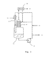
- Fig. 3 shows a preferred embodiment of the gas jet-absorption apparatus used in the invention.
- the high temperature gas mixture flows into a jet-absorption apparatus for quenching.
- An absorption solution is pressured by a circulation pump 14, and then ejected to the jet absorber via a nozzle of the jet absorber 12; the high temperature gas mixture is rapidly sucked into the jet absorber due to the negative pressure brought by the high speed flow of the solution, so as to achieve sufficient mixing of the solution and the gas mixture, and then quenching; the reaction product in an absorption trough 13 is further collected and absorbed by a liquid solvent.
- One part of the absorption solution in the absorption trough is transmitted via the circulation pump 14 to a phosgenation solution post-process system 15 for solvent removement and purification, another part is transmitted to the top of a packing tower 19 to wash the gas in the absorption trough 13, and the third part is transmitted to the jet absorber 12 for quenching and absorption of the high temperature gas mixture with a supplementing fresh solvent 16 together.
- the gas phase after going through the packing washing layer is further condensed in a condenser 18 (cooling medium is water), wherein partial solvent and products in the gas phase flow into the condenser 18 at atmospheric pressure, and incondensable gas is transmitted to a HCl and COCl 2 recycle device 17 so as to improve the post-treatment efficiency of phosgenation solution.
- a condenser 18 cooling medium is water
- HMDA 4,4'-diaminodicyclohexylmethane
- phosgene and nitrogen in a mole ratio of 1:4:1, continuously flow to their corresponding feed tubes respectively.
- the downstream part of the reactor is connected with a gas jet absorption apparatus (for quenching) and an absorption tower for excess phosgene and hydrochloride.
- HMDA, phosgene and nitrogen are preheated to 360 °C prior to entering the reactor shown in Fig. 1 .
- the HMDA vapor is diluted with an equivalent amount of nitrogen by the mole of the HMDA to form a mixture, and then the mixture flows into flow ducts via six lateral holes in the internal feed tube; the inner diameters of lateral holes and flow ducts are 1.5 mm, the inner diameter of the internal feed tube is 12 mm, the inner diameter of the external feed tube is 30 mm, the inner diameter of the annular space 5 is 20 mm, the distance between lateral holes and the bottom of the annular space is 1 cm, the distance L from lateral holes to the starting point of the divergent channel is 5 cm, the angel ⁇ between the divergent channel and the stream flow direction in the internal feed tube is 20 degrees, and the inner diameter D of the reaction tube is 15 mm.
- the instantaneous flow direction of the amine vapor at the outlet of a single flow duct is tangent with a second suppositional circle defined by the center of jet holes, the center of outlets of flow ducts and the axis of the phosgene feed tube, and the diameter of the first suppositional circle is 0.65 times of the inner diameter of the internal feed tube.
- the vacuum in the reaction tube is maintained at - 400 mbar by the sucking effect of high speed liquid in the gas jet absorption apparatus (a complex vacuum system and cost are saved).
- the velocity of the mixture of the amine vapor and nitrogen through flow ducts is about 38 m/s
- the velocity of phosgene prior to the mixing is about 8 m/s.
- the reaction product HMDI is quenched to 140°C to 150 °C by a gas jet absorption apparatus with an o-dichlorobenzene solution of HMDI to obtain a phosgenation solution, and the o-dichlorobenzene solution is at 120 °C.
- the GC assay indicates that the content of HMDI in the phosgenation solution is 99.24% (normalization), and the yield of HMDI is 97.9% of the theory yield.
- Example 1 is repeated under the same conditions, but the flow duct type jet reactor is replaced by a central nozzle type jet comprising a central nozzle and an annular space wherein the cross sectional area of the central nozzle equals to the total cross sectional area of flow ducts, the area of the annular space between the central nozzle and the wall of the cylindrical reactor equals to the cross sectional area of the phosgene feed tube in Example 1 and the area of the reaction tube connected to the bottom of the mixer equals to that of the reaction tube in Example 1.
- a mixture of the amine vapor and nitrogen flows through the central nozzle, and phosgene flows through the annular space.
- the GC assay indicates that the content of HMDI in the phosgenation solution is 99.08% (normalization), and the yield of HMDI is 97.4% of the theory yield.
- the gas jet absorption apparatus is replaced by a solvent absorption tower to quench the high temperature gas mixture (which needs a complex vacuum system and an additional cooling system), and the rest is the same as Example 1,
- the yield of HMDI is 97.6% of the theory yield. It shows that the yield is relatively lower and the system is more complex by comparison.
- HMDA 4,4'-diaminodicyclohexylmethane
- phosgene and nitrogen in a mole ratio of 1:4:1, continuously flow to their corresponding feed tubes of the reactor shown in Fig. 1 respectively.
- HMDA, phosgene and nitrogen are preheated to 360° C prior to entering the reactor shown in Fig. 1 .
- a reactor similar to one in Example 1 is used, the HMDA vapor and nitrogen flows into flow ducts via four lateral holes in the internal feed tube; inner diameters of lateral holes and flow ducts are 2.0 mm, the inner diameter of the internal feed tube is 12 mm, the diameter of a first suppositional circle is 0.7 times of that of the internal feed tube and the rest parameters are the same as those in Example 1.
- the vacuum in the reaction tube is - 400 mbar, the velocity of the mixture of the amine vapor and nitrogen through flow ducts is about 34 m/s, and the velocity of phosgene prior to the mixing is about 8 m/s.
- the reaction product HMDI After emerging from the reaction tube of the reactor, the reaction product HMDI is quenched to 140°C to 150 °C by a gas jet absorption apparatus with an o-dichlorobenzene solution of HMDI to obtain a phosgenation solution, and the o-dichlorobenzene solution is at 120 °C.
- the yield of HMDI is 97.8% of the theory yield.
- IPDA Isophoronediamine
- phosgene phosgene and nitrogen
- a mole ratio of 1:4:1 continuously flow to the same reactor as one in Example 1.
- IPDA, phosgene and nitrogen Prior to entering the reactor, IPDA, phosgene and nitrogen are separately preheated to 320 °C. Under nearly the same reaction conditions, the yield of obtained IPDI is 98.8% of the theory.
Landscapes
- Chemical & Material Sciences (AREA)
- Organic Chemistry (AREA)
- Chemical Kinetics & Catalysis (AREA)
- Organic Low-Molecular-Weight Compounds And Preparation Thereof (AREA)
- Physical Or Chemical Processes And Apparatus (AREA)
Claims (16)
- Jetreaktor vom Strömungskanaltyp, umfassend:ein inneres Zuführrohr (3), ein externes Zuführrohr (4), koaxial zu dem inneren Zuführrohr, und einen Ringraum (5), welcher zwischen den beiden Zuführrohren definiert ist, wobei beide Enden des externen Zuführrohrs geschlossen sind; ein Reaktionsrohr (7), koaxial mit stromabwärts liegenden Bereich des inneren Zuführrohrs verbunden ist, Düsenlöcher (6) in der Wand des stromabwärts angeordneten Teils des inneren Zuführrohrs (3) ausgebildet sind und die Düsenlöcher (6) mit den Strömungskanälen (8) verbunden sind,wobei die Düsenlöcher (6) und die Strömungskanäle (8) in einer nahtlos ineinander übergehenden Weise verbunden sind, und die Anzahl der Düsenlöcher (6) und der Strömungskanäle (8), welche verbunden sind, 2 bis 20 beträgt, undwobei Auslässe der Strömungskanäle (8) in einem ersten angenommenen Kreis (9) koaxial zu dem inneren Zuführrohr angeordnet sind und symmetrisch an dem ersten angenommenen Kreis (9) angeordnet sind, und wobei der Durchmesser des ersten angenommenen Kreises (9) das 0,1- bis 0,99-fache des inneren Durchmessers des inneren Zuführrohrs beträgt, undwobei die Flussrichtung eines Ausgangsmaterials an den Auslässen der Strömungskanäle (8) tangential zu einem zweiten angenommenen Kreis (10) ist, welcher durch die Mittelpunkte der Düsenlöcher, die Mittelpunkte der Auslässe der Strömungskanäle und der Achse des inneren Zufuhrrohrs definiert ist; die Strömungskanäle (8) mit einer gekrümmten Form ausgebildet sind, und die Krümmung den zweiten angenommenen Kreis (10) überlappt.
- Jetreaktor vom Strömungskanaltyp nach Anspruch 1, wobei die gesamte Querschnittsfläche aller Düsenlöcher (6) oder Strömungskanäle (8) 2 bis 30 % der des inneren Zuführrohrs beträgt; die Düsenlöcher (6) so nah wie möglich an dem Boden des Ringraums (5), welcher von dem inneren Zuführrohr (3) und dem externen Zuführrohr (4) gebildet ist, angeordnet sind.
- Jetreaktor vom Strömungskanaltyp nach Anspruch 2, wobei alle oder Teile der Düsenlöcher (6) auf dem gleichen Querschnitt des inneren Zuführrohrs (3) angeordnet sind, und symmetrisch in der Wand des inneren Zuführrohrs angeordnet sind; die Düsenlöcher (6) nicht mehr als 10 cm von dem Boden des Ringraums (5) angeordnet sind; Auslässe der Strömungskanäle (8) auf dem gleichen Querschnitt des inneren Zuführrohrs (3) angeordnet sind.
- Jetreaktor vom Strömungskanaltyp nach Anspruch 3, wobei ein divergierender Kanal an dem stromabwärts angeordneten Ende des inneren Zuführrohrs (3) angeordnet ist, und mit einem Reaktionsrohr (7) verbunden ist; der Innendurchmesser des Reaktionsrohrs das ein- bis zweifache des inneren Zuführrohrs beträgt; der Abstand von den Düsenlöchern (6) zu dem Ausgangspunkt des divergierenden Kanals das 1- bis 15-fache des Durchmessers des inneren Zuführrohrs beträgt und der Winkel zwischen dem divergierenden Kanal und der Strömungsrichtung in dem inneren Zuführrohr 10 bis 30 Grad beträgt.
- Jetreaktor vom Strömungskanaltyp nach Anspruch 4, wobei das äußere Zuführrohr poröse Platten, Prallplatten oder Packungslagen (packing layers) im Inneren aufweist.
- Jetreaktor vom Strömungskanaltyp nach Anspruch 5, wobei die Anzahl der Strömungskanäle (8) 3 bis 10 beträgt; der Durchmesser des ersten angenommenen Kreises (9), das 0,4- bis 0,9-fache des Innendurchmessers des inneren Zuführrohrs beträgt; die gesamte Querschnittsfläche aller Düsenlöcher (6) oder der Strömungskanäle (8) 5 bis 15 % der Fläche des inneren Zuführrohrs beträgt; und der Abstand von den Düsenlöchern (6) zu dem Ausgangspunkt des divergierenden Kanals das 3- bis 6-fache des Durchmessers des inneren Zuführrohrs beträgt.
- Verfahren einer Gasphasenphosgenierung zur Herstellung aliphatischer, alicyclischer oder aromatischer Isocyanate mit einer allgemeinen Formel R(NCO)n unter Verwendung des Jetreaktors vom Strömungskanaltyp nach einem der Ansprüche 1 bis 6, wobei eine aliphatische, alicyclische oder aromatische Kohlenwasserstoffgruppe mit 1 bis 15 Kohlenstoffatome angibt und n eine ganze Zahl von 1 bis 10 ist, wobei das Verfahren die folgenden Schritte umfasst:a) ein Amin mit einer allgemeinen Formel R(NH2)n und Phosgen werden jeweils auf 120 °C bis 150 °C erwärmt, um in Gas verwandelt zu werden, wobei R und N wie oben definiert sind;b) Phosgen tritt durch das innere Zuführrohr (3) des Reaktors (1) ein und fließt parallel durch dieses hindurch, und der Amindampf tritt durch das externe Zuführrohr (4) über dessen Einlass (2) ein und wird anschließend in das innere Zuführrohr (3) über die Düsenlöcher (6) und Strömungskanäle (8) eingeführt;c) Phosgen und Amindampf werden vermischt und treten in das Reaktionsrohr (7) ein, um zu reagieren.
- Verfahren nach Anspruch 7, wobei das Verfahren den weiteren Schritt (d) umfasst: die aus dem Reaktionsrohr austretende Hochtemperaturgasmischung wird abgeschreckt.
- Verfahren nach Anspruch 8, wobei in dem Schritt (d) die Hochtemperaturgasmischung (11) durch eine Jetabsorptionsvorrichtung umfassend einen Flüssig-Gas Jetabsorber (12), eine Zirkulationspumpe (14), in einer Absorptionswanne (13) abgeschreckt wird.
- Verfahren nach Anspruch 9, wobei die mittlere Geschwindigkeit des Amindampfes durch alle Düsenlöcher (6) und Strömungskanäle (8) 6 bis 120 m/s beträgt und die mittlere Geschwindigkeit des Phosgens durch das innere Zuführrohr (3) 3 bis 20 m/s beträgt; das Geschwindigkeitsverhältnis des Amindampfes an den Auslässen der Strömungskanäle (8) zu Phosgen 1:1 bis 10:1 beträgt.
- Verfahren nach Anspruch 10, wobei in dem Schritt (a) der Amindampf mit einem inerten Gas oder mit einem inerten Lösungsmitteldampf verdünnt wird; das inerte Gas gewählt ist aus Stickstoff oder Argon; das inerte Lösungsmittel gewählt ist aus Toluol, Xylol, Chlorbenzol, o-Dichlorbenzol oder Decalin.
- Verfahren nach Anspruch 11, wobei während der Phosgenierung des Schrittes (c) der absolute Druck in den Zuführrohren (3, 4) 200 bis 3.000 mbar beträgt, und der Auslassdruck des Reaktionsrohres des Reaktors 150 bis 1.500 mbar beträgt; die Geschwindigkeit des Amindampfes an den Auslässen der Düsenlöcher (6) im Allgemeinen 6 bis 120 m/s beträgt.
- Verfahren nach Anspruch 12, wobei in Schritt (d) die Absorptionslösung in der Absorptionswanne (13) eine Temperatur von 130 bis 150 °C aufweist und gewählt ist aus reinen Lösungsmitteln umfassend Toluol, Xylol, Chlorbenzol oder o-Dichlorbenzol, oder einer Mischung jeder der vorgenannten Lösungsmittel mit 5 Gew.-% bis 50 Gew.-% aliphatischer, alicyclischer oder aromatischer Isocyanate von R(NCO)n.
- Verfahren nach Anspruch 13, wobei in dem Schritt (d) der Flüssig-Gas Jetabsorber (12) ein venturiartiger ist, ein rotierender Jet mit langen Rohren oder ein mehrdüsiger Jet, und wobei der Jetabsorber einstufig oder mehrstufig ist; ein statischer Mischer an dem Auslass des Jetabsorbers angeordnet ist; der Hochgeschwindigkeitsausstoß der Flüssigkeiten im Inneren des Jetabsorbers dem Reaktionssystem ein Vakuum von 0 mbar bis 700 mbar bereitstellt.
- Verfahren nach einem der Ansprüche 7 bis 14, wobei das Isozyanat gewählt ist aus einem der folgenden Chemikalien: 1,4-Butandiisocyanat, 1,6-Hexamethylendiisocyanat, 1,4-Cyklohexandiisocyanat, Isophoren, Diisocyanat, Dicyklohexylmethan-4,4'-diisocyanat, Nonantriisocyanat oder Toluol-2,4-diisocyanat.
- Verfahren nach einem der Ansprüche 7 bis 14, wobei das Amin mit der allgemeinen Formel R(NH2)n gewählt ist aus einer der folgenden Chemikalien: 1,4-Diaminobutan, 1,6-Diaminohexan, 1.4-Diaminocyklohexan, 1-Amino-3,3,5-trimethyl-5-aminomethylcyclohexan, 4,4'-Diaminodicyklohexylmethan, Triaminononan, eine Mischung aus 2,4-/2,6-Toluoldiaminen mit einem Isomerverhältnis von 80/20 bis 65/35 oder reines 2,4-Toluoldiamin.
Applications Claiming Priority (1)
| Application Number | Priority Date | Filing Date | Title |
|---|---|---|---|
| PCT/CN2007/002526 WO2009023989A1 (fr) | 2007-08-21 | 2007-08-21 | Réacteur à jet avec des conduits d'écoulement et procédé de fabrication d'isocyanates à l'aide de celui-ci |
Publications (3)
| Publication Number | Publication Date |
|---|---|
| EP2179985A1 EP2179985A1 (de) | 2010-04-28 |
| EP2179985A4 EP2179985A4 (de) | 2010-07-28 |
| EP2179985B1 true EP2179985B1 (de) | 2013-04-10 |
Family
ID=40377803
Family Applications (1)
| Application Number | Title | Priority Date | Filing Date |
|---|---|---|---|
| EP07800746.5A Active EP2179985B1 (de) | 2007-08-21 | 2007-08-21 | Mit strömungsleitungen ausgestatteter jetreaktor, verfahren zur herstellung von isocyanaten mittels eines solchen reaktors |
Country Status (5)
| Country | Link |
|---|---|
| US (1) | US8206652B2 (de) |
| EP (1) | EP2179985B1 (de) |
| JP (1) | JP5595271B2 (de) |
| KR (1) | KR101179459B1 (de) |
| WO (1) | WO2009023989A1 (de) |
Families Citing this family (19)
| Publication number | Priority date | Publication date | Assignee | Title |
|---|---|---|---|---|
| DE102009032414A1 (de) * | 2009-07-09 | 2011-01-13 | Bayer Materialscience Ag | Verfahren zur Herstellung von Isocyanaten in der Gasphase |
| EP2335816A3 (de) * | 2009-12-15 | 2012-02-29 | Vaillant GmbH | Vorrichtung zum Mischen von heißen Strömen |
| US20110228630A1 (en) * | 2010-03-16 | 2011-09-22 | Dow Global Technologies, Inc. | Reduced Transit Static Mixer Configuration |
| JP5934702B2 (ja) * | 2010-06-14 | 2016-06-15 | ダウ グローバル テクノロジーズ エルエルシー | 静的反応性ジェットミキサ、および、アミン−ホスゲン混合プロセスの間に混合する方法 |
| HUE036624T2 (hu) * | 2010-09-28 | 2018-07-30 | Dow Global Technologies Llc | Reaktív folyadék statikus keverõ keresztáramú akadályokkal, és keverési eljárás |
| JP2014534053A (ja) | 2011-09-30 | 2014-12-18 | ダウ グローバル テクノロジーズ エルエルシー | アミンのホスゲン化のための高度に分離されたジェットミキサ |
| KR20170058927A (ko) * | 2014-09-19 | 2017-05-29 | 코베스트로 도이칠란트 아게 | 이소시아네이트의 기체 상 제조 방법 |
| CN106111033B (zh) * | 2016-08-20 | 2018-05-15 | 开封市九泓化工有限公司 | 用于密封常压反应釜放空口的密封装置 |
| KR101906184B1 (ko) * | 2016-12-05 | 2018-10-10 | 한국원자력연구원 | 배관 혼합 장치 |
| KR101911298B1 (ko) * | 2018-04-18 | 2018-10-24 | 한국원자력연구원 | 배관 혼합 장치 |
| KR101916735B1 (ko) * | 2018-04-18 | 2018-11-08 | 한국원자력연구원 | 배관 혼합 장치 |
| CN108554347A (zh) * | 2018-05-31 | 2018-09-21 | 苏州市金翔钛设备有限公司 | 带文丘里管结构的反应釜 |
| KR20210034608A (ko) * | 2018-07-30 | 2021-03-30 | 다우 글로벌 테크놀로지스 엘엘씨 | 포스겐과 유기 아민을 혼합하기 위한 정적 혼합 디바이스 및 방법 |
| KR101972096B1 (ko) * | 2018-10-01 | 2019-04-24 | 한국원자력연구원 | 배관 혼합 장치 |
| CN110327848B (zh) * | 2019-05-29 | 2022-02-18 | 江苏蓝丰生物化工股份有限公司 | 一种用于光气化反应的装置、光气化反应的生产工艺 |
| CN111167385B (zh) * | 2020-01-10 | 2022-03-01 | 天津大学 | 利用醛原料和空气制备酸的喷射型气液反应器 |
| CN111138267A (zh) * | 2020-01-10 | 2020-05-12 | 天津大学 | 一种利用低碳醛通过空气氧化制备低碳酸的方法 |
| HUP2300387A1 (hu) * | 2021-01-11 | 2024-01-28 | Wanhua Chemical Ningbo Co | Eljárás poliizocianát elõállítására és reagáltató berendezés ehhez |
| CN114210219A (zh) * | 2021-12-01 | 2022-03-22 | 陈晓彬 | 一种物料混合旋涡加速装置 |
Family Cites Families (13)
| Publication number | Priority date | Publication date | Assignee | Title |
|---|---|---|---|---|
| US571196A (en) * | 1896-11-10 | Gas-mixing apparatus | ||
| US3190618A (en) * | 1963-04-30 | 1965-06-22 | Katzen Raphael | Fluid mixer |
| US3207484A (en) * | 1963-06-20 | 1965-09-21 | Ind Process Engineers Inc | Fluid mixing device |
| SE372553B (de) * | 1972-10-13 | 1974-12-23 | Aga Ab | |
| DE3714439A1 (de) | 1987-04-30 | 1988-11-10 | Bayer Ag | Verfahren zur herstellung von (cyclo)aliphatischen diisocyanaten |
| DE3744001C1 (de) * | 1987-12-24 | 1989-06-08 | Bayer Ag | Verfahren zur kontinuierlichen Herstellung von Mono- oder Polyisocyanaten |
| DE19540292C1 (de) | 1995-10-28 | 1997-01-30 | Karlsruhe Forschzent | Statischer Mikrovermischer |
| JP2000213681A (ja) * | 1999-01-27 | 2000-08-02 | Toshiba Corp | 流体混合継手 |
| US6623154B1 (en) * | 2000-04-12 | 2003-09-23 | Premier Wastewater International, Inc. | Differential injector |
| DE10019414C2 (de) * | 2000-04-19 | 2003-06-12 | Ballard Power Systems | Vorrichtung zum Einleiten von Gas in einen Rohrabschnitt |
| DE10133729A1 (de) | 2001-07-11 | 2003-01-23 | Bayer Ag | Verfahren zur Herstellung von (cyclo)aliphatischen Diisocyanaten |
| DE10245704A1 (de) * | 2002-09-30 | 2004-04-01 | Bayer Ag | Verfahren zum Quenchen eines gasförmigen Reaktionsgemisches bei der Gasphasenphosgenierung von Diaminen |
| DE602006003419D1 (de) * | 2005-04-08 | 2008-12-11 | Huntsman Int Llc | Spiralmischerdüse und verfahren zum mischen von zwei oder mehr fluiden und verfahren zur herstellung von isocyanaten |
-
2007
- 2007-08-21 EP EP07800746.5A patent/EP2179985B1/de active Active
- 2007-08-21 JP JP2010521278A patent/JP5595271B2/ja active Active
- 2007-08-21 KR KR1020107006008A patent/KR101179459B1/ko active IP Right Grant
- 2007-08-21 US US12/674,121 patent/US8206652B2/en active Active
- 2007-08-21 WO PCT/CN2007/002526 patent/WO2009023989A1/zh active Application Filing
Also Published As
| Publication number | Publication date |
|---|---|
| JP2010536803A (ja) | 2010-12-02 |
| KR101179459B1 (ko) | 2012-09-07 |
| US8206652B2 (en) | 2012-06-26 |
| WO2009023989A1 (fr) | 2009-02-26 |
| EP2179985A4 (de) | 2010-07-28 |
| EP2179985A1 (de) | 2010-04-28 |
| US20110124907A1 (en) | 2011-05-26 |
| KR20100044273A (ko) | 2010-04-29 |
| JP5595271B2 (ja) | 2014-09-24 |
Similar Documents
| Publication | Publication Date | Title |
|---|---|---|
| EP2179985B1 (de) | Mit strömungsleitungen ausgestatteter jetreaktor, verfahren zur herstellung von isocyanaten mittels eines solchen reaktors | |
| CN101372463B (zh) | 导流管型射流反应器及利用该反应器制备异氰酸酯的方法 | |
| JP5254234B2 (ja) | 穴噴射型リアクターおよびこれを用いたイソシアナートの製造方法 | |
| CN100572358C (zh) | 异氰酸酯的制备方法 | |
| KR101433943B1 (ko) | 이소시아네이트의 기상 제조 방법 | |
| JP4486800B2 (ja) | ジアミンの気相ホスゲン化の際に気体反応混合物をクエンチする方法 | |
| US8957245B2 (en) | Method for producing isocyanate | |
| JP5548684B2 (ja) | イソシアネートの製造方法 | |
| KR20100067626A (ko) | 기체상에서의 이소시아네이트의 제조 방법 | |
| US11542228B2 (en) | Method and device for preparing diisocyanate | |
| CN111094240B (zh) | 使在二胺的气相光气化中获得的气态反应混合物骤冷的方法 | |
| CN107667089A (zh) | 在气相中制备二异氰酸酯的方法 | |
| CN101623615A (zh) | 套筒分布式气相光气化反应器及用于合成异氰酸酯的方法 | |
| CN104874335A (zh) | 一种制备异氰酸酯的反应器及其用于制备异氰酸酯的方法 | |
| WO2009068920A1 (en) | Mixing device for mixing two liquids and process for the continuous preparation of organic mono-, di- or polyisocyanates | |
| CN215102944U (zh) | 由有机胺光气化制备异氰酸酯的反应系统 | |
| CN107597028B (zh) | 一种制备异氰酸酯的反应器及方法 |
Legal Events
| Date | Code | Title | Description |
|---|---|---|---|
| PUAI | Public reference made under article 153(3) epc to a published international application that has entered the european phase |
Free format text: ORIGINAL CODE: 0009012 |
|
| 17P | Request for examination filed |
Effective date: 20091218 |
|
| AK | Designated contracting states |
Kind code of ref document: A1 Designated state(s): AT BE BG CH CY CZ DE DK EE ES FI FR GB GR HU IE IS IT LI LT LU LV MC MT NL PL PT RO SE SI SK TR |
|
| AX | Request for extension of the european patent |
Extension state: AL BA HR MK RS |
|
| A4 | Supplementary search report drawn up and despatched |
Effective date: 20100630 |
|
| DAX | Request for extension of the european patent (deleted) | ||
| GRAP | Despatch of communication of intention to grant a patent |
Free format text: ORIGINAL CODE: EPIDOSNIGR1 |
|
| GRAS | Grant fee paid |
Free format text: ORIGINAL CODE: EPIDOSNIGR3 |
|
| GRAA | (expected) grant |
Free format text: ORIGINAL CODE: 0009210 |
|
| AK | Designated contracting states |
Kind code of ref document: B1 Designated state(s): AT BE BG CH CY CZ DE DK EE ES FI FR GB GR HU IE IS IT LI LT LU LV MC MT NL PL PT RO SE SI SK TR |
|
| REG | Reference to a national code |
Ref country code: GB Ref legal event code: FG4D |
|
| REG | Reference to a national code |
Ref country code: AT Ref legal event code: REF Ref document number: 605917 Country of ref document: AT Kind code of ref document: T Effective date: 20130415 Ref country code: CH Ref legal event code: EP |
|
| REG | Reference to a national code |
Ref country code: IE Ref legal event code: FG4D |
|
| REG | Reference to a national code |
Ref country code: DE Ref legal event code: R096 Ref document number: 602007029704 Country of ref document: DE Effective date: 20130606 |
|
| REG | Reference to a national code |
Ref country code: NL Ref legal event code: T3 |
|
| PG25 | Lapsed in a contracting state [announced via postgrant information from national office to epo] |
Ref country code: SI Free format text: LAPSE BECAUSE OF FAILURE TO SUBMIT A TRANSLATION OF THE DESCRIPTION OR TO PAY THE FEE WITHIN THE PRESCRIBED TIME-LIMIT Effective date: 20130410 |
|
| REG | Reference to a national code |
Ref country code: AT Ref legal event code: MK05 Ref document number: 605917 Country of ref document: AT Kind code of ref document: T Effective date: 20130410 |
|
| REG | Reference to a national code |
Ref country code: LT Ref legal event code: MG4D |
|
| PG25 | Lapsed in a contracting state [announced via postgrant information from national office to epo] |
Ref country code: FI Free format text: LAPSE BECAUSE OF FAILURE TO SUBMIT A TRANSLATION OF THE DESCRIPTION OR TO PAY THE FEE WITHIN THE PRESCRIBED TIME-LIMIT Effective date: 20130410 Ref country code: GR Free format text: LAPSE BECAUSE OF FAILURE TO SUBMIT A TRANSLATION OF THE DESCRIPTION OR TO PAY THE FEE WITHIN THE PRESCRIBED TIME-LIMIT Effective date: 20130711 Ref country code: AT Free format text: LAPSE BECAUSE OF FAILURE TO SUBMIT A TRANSLATION OF THE DESCRIPTION OR TO PAY THE FEE WITHIN THE PRESCRIBED TIME-LIMIT Effective date: 20130410 Ref country code: PT Free format text: LAPSE BECAUSE OF FAILURE TO SUBMIT A TRANSLATION OF THE DESCRIPTION OR TO PAY THE FEE WITHIN THE PRESCRIBED TIME-LIMIT Effective date: 20130812 Ref country code: SE Free format text: LAPSE BECAUSE OF FAILURE TO SUBMIT A TRANSLATION OF THE DESCRIPTION OR TO PAY THE FEE WITHIN THE PRESCRIBED TIME-LIMIT Effective date: 20130410 Ref country code: LT Free format text: LAPSE BECAUSE OF FAILURE TO SUBMIT A TRANSLATION OF THE DESCRIPTION OR TO PAY THE FEE WITHIN THE PRESCRIBED TIME-LIMIT Effective date: 20130410 Ref country code: IS Free format text: LAPSE BECAUSE OF FAILURE TO SUBMIT A TRANSLATION OF THE DESCRIPTION OR TO PAY THE FEE WITHIN THE PRESCRIBED TIME-LIMIT Effective date: 20130810 Ref country code: ES Free format text: LAPSE BECAUSE OF FAILURE TO SUBMIT A TRANSLATION OF THE DESCRIPTION OR TO PAY THE FEE WITHIN THE PRESCRIBED TIME-LIMIT Effective date: 20130721 |
|
| PG25 | Lapsed in a contracting state [announced via postgrant information from national office to epo] |
Ref country code: LV Free format text: LAPSE BECAUSE OF FAILURE TO SUBMIT A TRANSLATION OF THE DESCRIPTION OR TO PAY THE FEE WITHIN THE PRESCRIBED TIME-LIMIT Effective date: 20130410 Ref country code: CY Free format text: LAPSE BECAUSE OF FAILURE TO SUBMIT A TRANSLATION OF THE DESCRIPTION OR TO PAY THE FEE WITHIN THE PRESCRIBED TIME-LIMIT Effective date: 20130410 Ref country code: BG Free format text: LAPSE BECAUSE OF FAILURE TO SUBMIT A TRANSLATION OF THE DESCRIPTION OR TO PAY THE FEE WITHIN THE PRESCRIBED TIME-LIMIT Effective date: 20130710 Ref country code: PL Free format text: LAPSE BECAUSE OF FAILURE TO SUBMIT A TRANSLATION OF THE DESCRIPTION OR TO PAY THE FEE WITHIN THE PRESCRIBED TIME-LIMIT Effective date: 20130410 |
|
| REG | Reference to a national code |
Ref country code: DE Ref legal event code: R082 Ref document number: 602007029704 Country of ref document: DE Representative=s name: GRUENECKER, KINKELDEY, STOCKMAIR & SCHWANHAEUS, DE |
|
| REG | Reference to a national code |
Ref country code: NL Ref legal event code: TD Effective date: 20140115 |
|
| PG25 | Lapsed in a contracting state [announced via postgrant information from national office to epo] |
Ref country code: CZ Free format text: LAPSE BECAUSE OF FAILURE TO SUBMIT A TRANSLATION OF THE DESCRIPTION OR TO PAY THE FEE WITHIN THE PRESCRIBED TIME-LIMIT Effective date: 20130410 Ref country code: SK Free format text: LAPSE BECAUSE OF FAILURE TO SUBMIT A TRANSLATION OF THE DESCRIPTION OR TO PAY THE FEE WITHIN THE PRESCRIBED TIME-LIMIT Effective date: 20130410 Ref country code: EE Free format text: LAPSE BECAUSE OF FAILURE TO SUBMIT A TRANSLATION OF THE DESCRIPTION OR TO PAY THE FEE WITHIN THE PRESCRIBED TIME-LIMIT Effective date: 20130410 Ref country code: DK Free format text: LAPSE BECAUSE OF FAILURE TO SUBMIT A TRANSLATION OF THE DESCRIPTION OR TO PAY THE FEE WITHIN THE PRESCRIBED TIME-LIMIT Effective date: 20130410 |
|
| REG | Reference to a national code |
Ref country code: DE Ref legal event code: R081 Ref document number: 602007029704 Country of ref document: DE Owner name: WANHUA CHEMICAL (NINGBO) CO., LTD., CN Free format text: FORMER OWNER: NINGBO WANHUA POLYURETHANES CO., LTD., NINGBO, CN Effective date: 20131216 Ref country code: DE Ref legal event code: R082 Ref document number: 602007029704 Country of ref document: DE Representative=s name: GRUENECKER, KINKELDEY, STOCKMAIR & SCHWANHAEUS, DE Effective date: 20131216 Ref country code: DE Ref legal event code: R081 Ref document number: 602007029704 Country of ref document: DE Owner name: WANHUA CHEMICAL (NINGBO) CO., LTD., NINGBO, CN Free format text: FORMER OWNER: NINGBO WANHUA POLYURETHANES CO., LTD., NINGBO, ZHEJIANG, CN Effective date: 20131216 Ref country code: DE Ref legal event code: R082 Ref document number: 602007029704 Country of ref document: DE Representative=s name: GRUENECKER PATENT- UND RECHTSANWAELTE PARTG MB, DE Effective date: 20131216 |
|
| PLBE | No opposition filed within time limit |
Free format text: ORIGINAL CODE: 0009261 |
|
| STAA | Information on the status of an ep patent application or granted ep patent |
Free format text: STATUS: NO OPPOSITION FILED WITHIN TIME LIMIT |
|
| PG25 | Lapsed in a contracting state [announced via postgrant information from national office to epo] |
Ref country code: RO Free format text: LAPSE BECAUSE OF FAILURE TO SUBMIT A TRANSLATION OF THE DESCRIPTION OR TO PAY THE FEE WITHIN THE PRESCRIBED TIME-LIMIT Effective date: 20130410 |
|
| REG | Reference to a national code |
Ref country code: FR Ref legal event code: CD Owner name: WANHUA CHEMICAL (NINGBO) CO., LTD., CN Effective date: 20140204 |
|
| 26N | No opposition filed |
Effective date: 20140113 |
|
| REG | Reference to a national code |
Ref country code: CH Ref legal event code: PL |
|
| GBPC | Gb: european patent ceased through non-payment of renewal fee |
Effective date: 20130821 |
|
| REG | Reference to a national code |
Ref country code: DE Ref legal event code: R097 Ref document number: 602007029704 Country of ref document: DE Effective date: 20140113 |
|
| PG25 | Lapsed in a contracting state [announced via postgrant information from national office to epo] |
Ref country code: MC Free format text: LAPSE BECAUSE OF FAILURE TO SUBMIT A TRANSLATION OF THE DESCRIPTION OR TO PAY THE FEE WITHIN THE PRESCRIBED TIME-LIMIT Effective date: 20130410 Ref country code: LI Free format text: LAPSE BECAUSE OF NON-PAYMENT OF DUE FEES Effective date: 20130831 Ref country code: CH Free format text: LAPSE BECAUSE OF NON-PAYMENT OF DUE FEES Effective date: 20130831 |
|
| REG | Reference to a national code |
Ref country code: IE Ref legal event code: MM4A |
|
| REG | Reference to a national code |
Ref country code: HU Ref legal event code: AG4A Ref document number: E018714 Country of ref document: HU |
|
| PG25 | Lapsed in a contracting state [announced via postgrant information from national office to epo] |
Ref country code: GB Free format text: LAPSE BECAUSE OF NON-PAYMENT OF DUE FEES Effective date: 20130821 Ref country code: IE Free format text: LAPSE BECAUSE OF NON-PAYMENT OF DUE FEES Effective date: 20130821 |
|
| PG25 | Lapsed in a contracting state [announced via postgrant information from national office to epo] |
Ref country code: MT Free format text: LAPSE BECAUSE OF FAILURE TO SUBMIT A TRANSLATION OF THE DESCRIPTION OR TO PAY THE FEE WITHIN THE PRESCRIBED TIME-LIMIT Effective date: 20130410 |
|
| PG25 | Lapsed in a contracting state [announced via postgrant information from national office to epo] |
Ref country code: LU Free format text: LAPSE BECAUSE OF NON-PAYMENT OF DUE FEES Effective date: 20130821 |
|
| REG | Reference to a national code |
Ref country code: FR Ref legal event code: PLFP Year of fee payment: 10 |
|
| REG | Reference to a national code |
Ref country code: FR Ref legal event code: PLFP Year of fee payment: 11 |
|
| REG | Reference to a national code |
Ref country code: FR Ref legal event code: PLFP Year of fee payment: 12 |
|
| PGFP | Annual fee paid to national office [announced via postgrant information from national office to epo] |
Ref country code: NL Payment date: 20230726 Year of fee payment: 17 |
|
| PGFP | Annual fee paid to national office [announced via postgrant information from national office to epo] |
Ref country code: TR Payment date: 20230801 Year of fee payment: 17 Ref country code: IT Payment date: 20230809 Year of fee payment: 17 |
|
| PGFP | Annual fee paid to national office [announced via postgrant information from national office to epo] |
Ref country code: HU Payment date: 20230725 Year of fee payment: 17 Ref country code: FR Payment date: 20230828 Year of fee payment: 17 Ref country code: DE Payment date: 20230808 Year of fee payment: 17 Ref country code: BE Payment date: 20230822 Year of fee payment: 17 |