EP2179775A2 - Abgedichtete Wabenstruktur und Herstellungsverfahren dafür - Google Patents
Abgedichtete Wabenstruktur und Herstellungsverfahren dafür Download PDFInfo
- Publication number
- EP2179775A2 EP2179775A2 EP09252434A EP09252434A EP2179775A2 EP 2179775 A2 EP2179775 A2 EP 2179775A2 EP 09252434 A EP09252434 A EP 09252434A EP 09252434 A EP09252434 A EP 09252434A EP 2179775 A2 EP2179775 A2 EP 2179775A2
- Authority
- EP
- European Patent Office
- Prior art keywords
- segment
- honeycomb structure
- plugged
- plugged honeycomb
- long
- Prior art date
- Legal status (The legal status is an assumption and is not a legal conclusion. Google has not performed a legal analysis and makes no representation as to the accuracy of the status listed.)
- Granted
Links
Images




Classifications
-
- B—PERFORMING OPERATIONS; TRANSPORTING
- B01—PHYSICAL OR CHEMICAL PROCESSES OR APPARATUS IN GENERAL
- B01D—SEPARATION
- B01D46/00—Filters or filtering processes specially modified for separating dispersed particles from gases or vapours
- B01D46/0001—Making filtering elements
-
- B—PERFORMING OPERATIONS; TRANSPORTING
- B01—PHYSICAL OR CHEMICAL PROCESSES OR APPARATUS IN GENERAL
- B01D—SEPARATION
- B01D46/00—Filters or filtering processes specially modified for separating dispersed particles from gases or vapours
- B01D46/24—Particle separators, e.g. dust precipitators, using rigid hollow filter bodies
- B01D46/2403—Particle separators, e.g. dust precipitators, using rigid hollow filter bodies characterised by the physical shape or structure of the filtering element
- B01D46/2418—Honeycomb filters
- B01D46/2451—Honeycomb filters characterized by the geometrical structure, shape, pattern or configuration or parameters related to the geometry of the structure
- B01D46/2478—Structures comprising honeycomb segments
-
- B—PERFORMING OPERATIONS; TRANSPORTING
- B01—PHYSICAL OR CHEMICAL PROCESSES OR APPARATUS IN GENERAL
- B01D—SEPARATION
- B01D46/00—Filters or filtering processes specially modified for separating dispersed particles from gases or vapours
- B01D46/24—Particle separators, e.g. dust precipitators, using rigid hollow filter bodies
- B01D46/2403—Particle separators, e.g. dust precipitators, using rigid hollow filter bodies characterised by the physical shape or structure of the filtering element
- B01D46/2418—Honeycomb filters
- B01D46/2451—Honeycomb filters characterized by the geometrical structure, shape, pattern or configuration or parameters related to the geometry of the structure
- B01D46/2455—Honeycomb filters characterized by the geometrical structure, shape, pattern or configuration or parameters related to the geometry of the structure of the whole honeycomb or segments
-
- B—PERFORMING OPERATIONS; TRANSPORTING
- B01—PHYSICAL OR CHEMICAL PROCESSES OR APPARATUS IN GENERAL
- B01D—SEPARATION
- B01D46/00—Filters or filtering processes specially modified for separating dispersed particles from gases or vapours
- B01D46/24—Particle separators, e.g. dust precipitators, using rigid hollow filter bodies
- B01D46/2403—Particle separators, e.g. dust precipitators, using rigid hollow filter bodies characterised by the physical shape or structure of the filtering element
- B01D46/2418—Honeycomb filters
- B01D46/2451—Honeycomb filters characterized by the geometrical structure, shape, pattern or configuration or parameters related to the geometry of the structure
- B01D46/2466—Honeycomb filters characterized by the geometrical structure, shape, pattern or configuration or parameters related to the geometry of the structure of the adhesive layers, i.e. joints between segments
-
- B—PERFORMING OPERATIONS; TRANSPORTING
- B01—PHYSICAL OR CHEMICAL PROCESSES OR APPARATUS IN GENERAL
- B01D—SEPARATION
- B01D46/00—Filters or filtering processes specially modified for separating dispersed particles from gases or vapours
- B01D46/24—Particle separators, e.g. dust precipitators, using rigid hollow filter bodies
- B01D46/2403—Particle separators, e.g. dust precipitators, using rigid hollow filter bodies characterised by the physical shape or structure of the filtering element
- B01D46/2418—Honeycomb filters
- B01D46/2451—Honeycomb filters characterized by the geometrical structure, shape, pattern or configuration or parameters related to the geometry of the structure
- B01D46/2482—Thickness, height, width, length or diameter
-
- B—PERFORMING OPERATIONS; TRANSPORTING
- B01—PHYSICAL OR CHEMICAL PROCESSES OR APPARATUS IN GENERAL
- B01D—SEPARATION
- B01D46/00—Filters or filtering processes specially modified for separating dispersed particles from gases or vapours
- B01D46/24—Particle separators, e.g. dust precipitators, using rigid hollow filter bodies
- B01D46/2403—Particle separators, e.g. dust precipitators, using rigid hollow filter bodies characterised by the physical shape or structure of the filtering element
- B01D46/2418—Honeycomb filters
- B01D46/2498—The honeycomb filter being defined by mathematical relationships
-
- F—MECHANICAL ENGINEERING; LIGHTING; HEATING; WEAPONS; BLASTING
- F01—MACHINES OR ENGINES IN GENERAL; ENGINE PLANTS IN GENERAL; STEAM ENGINES
- F01N—GAS-FLOW SILENCERS OR EXHAUST APPARATUS FOR MACHINES OR ENGINES IN GENERAL; GAS-FLOW SILENCERS OR EXHAUST APPARATUS FOR INTERNAL-COMBUSTION ENGINES
- F01N3/00—Exhaust or silencing apparatus having means for purifying, rendering innocuous, or otherwise treating exhaust
- F01N3/02—Exhaust or silencing apparatus having means for purifying, rendering innocuous, or otherwise treating exhaust for cooling, or for removing solid constituents of, exhaust
- F01N3/021—Exhaust or silencing apparatus having means for purifying, rendering innocuous, or otherwise treating exhaust for cooling, or for removing solid constituents of, exhaust by means of filters
- F01N3/022—Exhaust or silencing apparatus having means for purifying, rendering innocuous, or otherwise treating exhaust for cooling, or for removing solid constituents of, exhaust by means of filters characterised by specially adapted filtering structure, e.g. honeycomb, mesh or fibrous
- F01N3/0222—Exhaust or silencing apparatus having means for purifying, rendering innocuous, or otherwise treating exhaust for cooling, or for removing solid constituents of, exhaust by means of filters characterised by specially adapted filtering structure, e.g. honeycomb, mesh or fibrous the structure being monolithic, e.g. honeycombs
-
- B—PERFORMING OPERATIONS; TRANSPORTING
- B01—PHYSICAL OR CHEMICAL PROCESSES OR APPARATUS IN GENERAL
- B01D—SEPARATION
- B01D2279/00—Filters adapted for separating dispersed particles from gases or vapours specially modified for specific uses
- B01D2279/30—Filters adapted for separating dispersed particles from gases or vapours specially modified for specific uses for treatment of exhaust gases from IC Engines
-
- F—MECHANICAL ENGINEERING; LIGHTING; HEATING; WEAPONS; BLASTING
- F01—MACHINES OR ENGINES IN GENERAL; ENGINE PLANTS IN GENERAL; STEAM ENGINES
- F01N—GAS-FLOW SILENCERS OR EXHAUST APPARATUS FOR MACHINES OR ENGINES IN GENERAL; GAS-FLOW SILENCERS OR EXHAUST APPARATUS FOR INTERNAL-COMBUSTION ENGINES
- F01N2450/00—Methods or apparatus for fitting, inserting or repairing different elements
- F01N2450/02—Fitting monolithic blocks into the housing
-
- F—MECHANICAL ENGINEERING; LIGHTING; HEATING; WEAPONS; BLASTING
- F01—MACHINES OR ENGINES IN GENERAL; ENGINE PLANTS IN GENERAL; STEAM ENGINES
- F01N—GAS-FLOW SILENCERS OR EXHAUST APPARATUS FOR MACHINES OR ENGINES IN GENERAL; GAS-FLOW SILENCERS OR EXHAUST APPARATUS FOR INTERNAL-COMBUSTION ENGINES
- F01N2450/00—Methods or apparatus for fitting, inserting or repairing different elements
- F01N2450/28—Methods or apparatus for fitting, inserting or repairing different elements by using adhesive material, e.g. cement
-
- Y—GENERAL TAGGING OF NEW TECHNOLOGICAL DEVELOPMENTS; GENERAL TAGGING OF CROSS-SECTIONAL TECHNOLOGIES SPANNING OVER SEVERAL SECTIONS OF THE IPC; TECHNICAL SUBJECTS COVERED BY FORMER USPC CROSS-REFERENCE ART COLLECTIONS [XRACs] AND DIGESTS
- Y02—TECHNOLOGIES OR APPLICATIONS FOR MITIGATION OR ADAPTATION AGAINST CLIMATE CHANGE
- Y02T—CLIMATE CHANGE MITIGATION TECHNOLOGIES RELATED TO TRANSPORTATION
- Y02T10/00—Road transport of goods or passengers
- Y02T10/10—Internal combustion engine [ICE] based vehicles
- Y02T10/12—Improving ICE efficiencies
Definitions
- the present invention relates to a honeycomb structure and a method for manufacturing the honeycomb structure. More specifically, the present invention relates to a plugged honeycomb structure having a cutout portion and a method for manufacturing the plugged honeycomb structure.
- the honeycomb structure used for such a purpose generally has a plurality of cells separated by porous partition walls and functioning as fluid passages.
- the honeycomb structure has a structure where each of adjacent cells is plugged in the mutually opposite side end portion so that each end face of the honeycomb structure shows a checkerwise pattern.
- a fluid to be treated flows into the cells which are not plugged in the inflow hole side end face and are plugged in the outflow hole side end face, passes through the porous partition walls, and is discharged from the adjacent cells, that is, the cells which are plugged in the inflow hole side end face and are not plugged in the outflow hole end face.
- the partition walls function as a filter.
- particulate matter hereinbelow sometimes referred to as "PM"
- soot discharged from the diesel engine is trapped by the partition walls and deposits on the partition walls.
- such a honeycomb structure as described above is generally disposed in an exhaust gas flow passage on the downstream side of the engine as a DPF and has a function of passing and purifying the exhaust gas disposed from the engine.
- a peeled substance such as rust on an inner wall of a fluid passage, welding waste, a solid such as a garbage entered in a flow passage upon attachment, or liquid such as condensate water collides with the inner walls of the flow passages of the honeycomb structure disposed in the flow passage at high speed together with the exhaust gas to damage them.
- JP-A-9-206526 discloses a flow passage where an exhaust gas flow-shifting means and a foreign substance trapping portion are arranged in the flow passage on the upstream side of the honeycomb structure.
- the gas flow passage disclosed in JP-A-9-206526 physically traps foreign substances in exhaust gas in a pocket-shaped foreign substance-trapping portion disposed on the inner wall of the fluid passage and having an open portion facing toward the upstream direction of exhaust gas with shifting the flow of the exhaust gas toward the outer peripheral direction of the flow passage by the exhaust gas flow-shifting means and exhibits an effect against the erosion problem caused by bouncing of the foreign substance in the fluid passage.
- the exhaust gas flow passage needs to be long in the flow direction to cause a problem of increasing the size of the exhaust gas purification apparatus.
- the flow passage cross section is reduced to increase pressure loss, which may cause decrease in engine output.
- the present invention has been made in view of such problems of prior art and aims to provide a plugged honeycomb structure used in an exhaust gas purification apparatus having both an erosion inhibition effect and downsizing, capable of inhibiting purification performance and strength from deteriorating due to shape processing, and being excellent in raw material yield and costs.
- the inventors' earnest investigation they hit upon the idea of making the plugged honeycomb structure have a structure having a cutout portion in a part of a fluid passage end portion and having plugging portions also in an end portion of each of the predetermined cells constituting the cutout portion in a plugged honeycomb structure having a structure where each of adjacent cells is plugged in one end portion on the mutually opposite side to make the cutout portion effectively work for inhibition of erosion and to realize space saving by the volume of the cutout portion.
- the present inventors earnestly investigated various problems such as strength deterioration, regeneration limit deterioration, and pressure loss increase and hit upon the idea that the problems can be solved by specifying the thickness and the shape of the bonding material layer to predetermined ones in a plugged honeycomb structure obtained by integrally bonding a plurality of honeycomb segments by means of a bonding material layer, which led to the completion of the present invention. That is, according to the present invention, there are provided a plugged honeycomb structure having sufficient purification performance and strength and having a desired end face shape and a manufacturing method for the structure, that is, the following plugged honeycomb structure and a manufacturing method for the structure.
- a plugged honeycomb structure for a diesel particulate filter having a plurality of cells functioning as fluid passages separated by porous partition walls and plugging portions in such a manner that each of adjacent cells is plugged in one end portion on the mutually opposite side; wherein the plugged honeycomb structure has a cutout or recessed portion in a part of a fluid passage end portion, and predetermined cells constituting the cutout portion are plugged in such a manner that each of adjacent cells is plugged in one end portion on the mutually opposite side.
- a plugged honeycomb structure of the present invention it is possible to form a desired cutout portion in a fluid inflow hole side end portion to obtain a plugged honeycomb structure having an end portion shape in accordance with the purpose.
- a method for manufacturing a plugged honeycomb structure of the present invention there can be improved problems such as damages and deterioration in strength upon manufacturing and regeneration limit deterioration and pressure loss increase upon use.
- Fig. 1 is a perspective view schematically showing an embodiment of a conventional plugged honeycomb structure.
- FIG. 2 is a perspective view schematically showing another embodiment of a conventional plugged honeycomb structure.
- Fig. 3 is a perspective view schematically showing an embodiment of a plugged honeycomb structure of the present invention.
- Fig. 4 is a perspective view schematically showing another embodiment of a plugged honeycomb structure of the present invention.
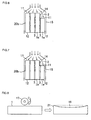
- FIG. 5A is a cross-sectional view schematically showing an embodiment of an exhaust gas purification apparatus equipped with a plugged honeycomb structure of the present invention.
- Fig. 5B is a cross-sectional view schematically showing another embodiment of an exhaust gas purification apparatus equipped with a plugged honeycomb structure of the present invention.
- FIG. 5C is a cross-sectional view schematically showing still another embodiment of an exhaust gas purification apparatus equipped with a plugged honeycomb structure of the present invention.
- Fig. 6 is a cross-sectional view schematically showing a scene where exhaust gas flows into an embodiment of a plugged honeycomb structure of the present invention.
- Fig. 7 is a cross-sectional view schematically showing a scene where exhaust gas flows into another embodiment of a plugged honeycomb structure of the present invention.
- Fig. 8 is a process drawing schematically showing a step where a depression is formed on a side face of a honeycomb segment.
- Fig. 9 is a process drawing schematically showing a step where an arc shaped curve is formed over a whole honeycomb segment.
- Fig. 10 is a cross-sectional view schematically showing a state that a short segment is obliquely bonded with respect to a long segment using a bonding material spacer.
- Fig. 11 is a partial cross-sectional view in an axial direction schematically showing a plugged honeycomb structure before cutting the long plugging portions formation side end portion.
- Fig. 12 is a partial cross-sectional view in an axial direction schematically showing a plugged honeycomb structure after cutting the long plugging portions formation side end portion.
- Fig. 13 is a schematic front view of an embodiment of a plugged honeycomb structure of the present invention viewed from a cutout portion formation direction.
- Fig. 14 is a schematic front view of another embodiment of a plugged honeycomb structure of the present invention viewed from a cutout portion formation direction.
- Fig. 15 is a process drawing schematically showing a step of piling up honeycomb segments.
- Fig. 16 is a perspective view schematically showing one embodiment of a honeycomb segment layered body.
- 1 honeycomb segment, 1a: short segment, 1b: long segment, 2: cutout portion, 3: bonding material layer, 5: cell, 6: partition wall, 8: DPF, 9: honeycomb catalyst body, 10, 10a, 10b, 20, 20a, 20b: plugged honeycomb structure, 11: inflow hole side end face, 12: outflow hole side end face, 13: foreign substance-trapping pocket, 14: corner portion of cutout portion, 15: container, 16: depression, 17: pressing means, 18: curve-forming embossing means, 19: bonding material spacer, 21: depressed segment, 22: arc-shaped segment, 23: oblique segment, 24: long plugging portion, 25: plugging portion, 26: end mill, 30: honeycomb segment layered body, 110, 120, and 130: exhaust gas purification apparatus
- Figs. 1 and 2 are perspective views each schematically showing an embodiment of a conventional plugged honeycomb structure.
- Figs. 3 and 4 are perspective views each schematically showing an embodiment of a plugged honeycomb structure of the present invention.
- Figs. 5A to 5C are cross-sectional views each schematically showing an embodiment of an exhaust gas purification apparatus equipped with a plugged honeycomb structure of the present invention.
- the observers' left side of the figures is the exhaust gas inflow hole side
- the observers' right side of the figures is the exhaust gas outflow hole side.
- a plugged honeycomb structure 10a integrally formed into a desired shape in advance, having a plurality of cells 5 separated by porous partition walls 6 and functioning as fluid passages, and plugged in such a manner that each of adjacent cells 5 is plugged in a passage end portion on the mutually opposite side to form plugging portions 25.
- a plugged honeycomb structure 10a integrally formed into a desired shape in advance, having a plurality of cells 5 separated by porous partition walls 6 and functioning as fluid passages, and plugged in such a manner that each of adjacent cells 5 is plugged in a passage end portion on the mutually opposite side to form plugging portions 25.
- a cylindrical plugged honeycomb structure 10 having no unevenness in the end portion in the axial direction as the plugged honeycomb structure 10b having honeycomb segments 1 each having a plurality of cells 5 separated by porous partition walls 6 and functioning as fluid passages and being integrally bonded together by means of the bonding material layer 3 to be formed into a desired shape, followed by plugging of the cells 5 in such a manner that each of adjacent cells 5 is plugged in a passage end portion on the mutually opposite side to form plugging portions 25.
- a plugged honeycomb structure of the present invention is, as shown in Figs. 3 and 4 , a plugged honeycomb structure 20 to serve as a diesel particulate filter having a plurality of cells 5 separated by porous partition walls 6 and functioning as fluid passages, the cells 5 each being plugged on one end portion in such a manner that each of adjacent cells 5 is plugged on the mutually opposite side to form plugging portions 25, the honeycomb structure having a cutout portion 2 in a part of a fluid passage end portion, and predetermined cells 5 constituting the cutout portion 2 each being plugged in one end portion in such a manner that each of adjacent cells 5 is plugged on the mutually opposite side.
- a plugged honeycomb structure 20 of the present invention for example, as shown in Fig. 3 , there is a unitary type plugged honeycomb structure 20a formed into a desired shape in advance and having plugging portions 25 formed in such a manner that each of adjacent cells 5 is plugged on one end portion on the mutually opposite side, where the structure has a cutout portion 2 in a part of the fluid passage end portion, and each of the predetermined cells 5 constituting the cutout portion 2 is also plugged in one end portion in such a manner that each of adjacent cells 5 is plugged on the mutually opposite side.
- Fig. 3 there is a unitary type plugged honeycomb structure 20a formed into a desired shape in advance and having plugging portions 25 formed in such a manner that each of adjacent cells 5 is plugged on one end portion on the mutually opposite side, where the structure has a cutout portion 2 in a part of the fluid passage end portion, and each of the predetermined cells 5 constituting the cutout portion 2 is also plugged in one end portion in such a manner that each
- a bonded type plugged honeycomb structure 20b obtained by integrally bonding a plurality of honeycomb segments 1 (1a, 1b) each having a plurality of cells 5 separated by porous partition walls 6 and functioning as fluid passages and having plugging portions 25 formed in such a manner that each of adjacent cells 5 is plugged in one end portion on the mutually opposite side by means of the bonding material layer 3 and then forming the bonded honeycomb segments into a desired shape, where the structure has a cutout portion 2 in a part of the fluid passage end portion, and each of the predetermined cells 5 constituting the cutout portion 2 is also plugged in one end portion in such a manner that each of adjacent cells 5 is plugged on the mutually opposite side.
- the whole shape of a plugged honeycomb structure 20 of the present invention is a desired shape suitable for an exhaust gas purification filter, such as a cylindrical shape or an oval shape, with a cutout portion 2 in the fluid passage end portion.
- the cutout portion 2 is formed to have a desired size at a desired position in accordance with the application and the purpose.
- plugging is performed to the predetermined cells 5 in the whole range of the passage end face including the cutout portion 2 to suppress deterioration in purification performance due to shape processing.
- ceramic is preferable, and it is preferably at least one kind selected from the group consisting of silicon carbide, silicon-silicon carbide based composite material, cordierite, mullite, alumina, spinel, silicon carbide-cordierite based composite material, lithium aluminum silicate, aluminum titanate, and iron-chrome-aluminum based alloy.
- silicon carbide silicon-silicon carbide based composite material
- cordierite cordierite
- mullite alumina
- spinel silicon carbide-cordierite based composite material
- lithium aluminum silicate aluminum titanate
- iron-chrome-aluminum based alloy iron-chrome-aluminum based alloy
- silicon carbide or silicon-silicon carbide based composite material is more preferable among these materials. Since silicon carbide has relatively large thermal expansion coefficient, a honeycomb structure formed by the use of silicon carbide as the framework and having a large size sometimes causes a defect due to thermal shock upon use. However, in a structure where a plurality of honeycomb segments 1 are integrally bonded together by means of the bonding material layer 3, the bonding material layer 3 buffers expansion and contraction of silicon carbide to inhibit a defect in the honeycomb segment 1 from generating.
- the material for the bonding material layer 3 there can be used a slurried material obtained by dispersing a filler such as inorganic fibers, colloidal silica, clay, SiC particles, an organic binder, and a resin balloon in a dispersion medium such as water.
- a filler such as inorganic fibers, colloidal silica, clay, SiC particles, an organic binder, and a resin balloon in a dispersion medium such as water.
- a plugged honeycomb structure 20 having the cutout portion 2 formed therein is disposed as the DPF at the back of the honeycomb catalyst body 9 in the container 15.
- the DPF 8 is positioned in such a manner that the cutout portion 2 faces the exhaust gas upstream side and faces downward (toward ground) of the exhaust gas purification apparatus 110 when the exhaust gas purification apparatus 110 is mounted on a vehicle. Solid and liquid foreign matters flowing from the upstream side of the exhaust gas flow go downward of the exhaust gas purification apparatus 110 according to the gravity. Therefore, damages tend to concentrate particularly in the lower portions of the inner walls of the container 15 and the inflow hole side end face 11 of the DPF 8.
- a space for the foreign substances can be secured in the lower portions portion of the container 15 to reduce frequency of direct collision of foreign substances with the end face of the DPF 8 and shock upon collision. That is, by the use of a plugged honeycomb structure 20 of the present invention, deterioration in durability due to erosion can be inhibited even without extra equipment such as a wire mesh or a foreign substance-trapping pocket in the flow passage of the exhaust gas purification apparatus, and space saving and cost saving can be realized in the exhaust gas purification apparatus.
- the plugged honeycomb structure 20 having the cutout portion 2 formed therein is disposed as a DPF 8 at the back of the honeycomb catalyst body 9 in the container 15, and the foreign substance-trapping pocket 13 for trapping foreign substances flowing from the upstream together with exhaust gas and causing damages in the DPF 8 is further provided to allow the cutout portion 2 of the DPF 8 to function as an introduction passage to release the foreign substances toward the foreign substance-trapping pocket 13.
- Such a constitution enables a large amount of foreign substances flowing into the apparatus to be collected in the foreign substance-trapping pocket 13 without allowing the foreign substances to collide with the inflow hole side end face 11 of the DPF 8.
- the DPF 8 is positioned in such a manner that the cutout portion 2 faces the exhaust gas upstream side and faces downward (toward ground) of the exhaust gas purification apparatus 120 when the exhaust gas purification apparatus 120 is mounted on a vehicle.
- the plugged honeycomb structure 20 of the present invention has an advantage of not only exhibiting an erosion inhibition effect in a limited space, but also being responsive to a container 15 having a specific shape as shown in Fig. 5C .
- a restriction in the usable space such as a lower portion of a vehicle
- a honeycomb structure having a shape according to the container shape is required, and, therefore, a plugged honeycomb structure 20 of the present invention is suitably used.
- Fig. 6 is a cross-sectional view schematically showing a scene where exhaust gas flows into an embodiment of a plugged honeycomb structure of the present invention
- Fig. 7 is a cross-sectional view schematically showing a scene where exhaust gas flows into another embodiment of a plugged honeycomb structure of the present invention.
- a plugged honeycomb structure 20b of the present invention as shown in Fig. 7 , it is preferable that the relation between an average thickness Ts(in) on a fluid inflow hole side end face 11 (here, cutout portion formation side end face) of the bonding material layer 3 bonding a short segment 1a and a long segment 1b together and an average thickness T (in) on the fluid inf low hole side end face of the bonding material layer bonding the short segment 1a to another short segment 1a or bonding the long segment 1b to another long segment 1b is Ts(in) > T(in).
- Ts(in) (1.1 to 5.0) ⁇ T(in)
- unevenness of PM deposition in the short segment 1a cannot be inhibited, and a crack generation inhibition effect cannot be obtained, which is not preferable.
- Ts(in) > 5.0 ⁇ T(in) thermal conductivity between the long segment 1b and the short segment 1a is deteriorated to increase the temperature difference caused upon PM regeneration, and a crack is easily caused, which is not preferable.
- the relation between the average thickness Ts (out) on an fluid outflow hole side end face 12 and the aforementioned average thickness Ts(in) of the bonding material layer 3 for bonding the short segment 1a and the long segment 1b is Ts (out) ⁇ Ts (in) and that the thickness of the bonding material layer 3 is gradually reduced from the average thickness Ts (in) toward the average thickness Ts (out) .
- Such a design enables to suppress the decrease in the filter area at minimum and inhibit increase in pressure loss upon use.
- the relation between the aforementioned average thickness Ts(out) and the average thickness Ts(in) is Ts(out) ⁇ 0.9 ⁇ Ts(in) and Ts(out) ⁇ 0.2 mm.
- Ts(out) ⁇ 0.2 mm heat transfer from the long segment 1b to the short segment 1a upon PM regeneration increases to increase the temperature difference between the outer peripheral portion and the inner portion, and thereby a crack may be caused easily starting on the long segment 1b.
- Ts(out) > 0.9 ⁇ Ts(in) an effect in inhibiting pressure loss from increasing by securing the filter area may not be obtained sufficiently.
- a depressed segment 21 having a depression 16 in an axial direction in at least one of the side faces is preferably used. More specifically, it is preferable to use, as the short segment 1a, a depressed segment 21 obtained by forming a depression 16 using a pressing means 17 such as a roller on at least one of the side faces of the honeycomb segment 1 still having flexibility before drying and firing before bonding.
- Fig. 8 is a process drawing schematically showing a step where a depression is formed on a side face of a honeycomb segment.
- the curved shape, the depth, and the like of the depression 16 can be made as desired in accordance with the depth of the bonding material layer of the plugged honeycomb structure 20b to be obtained.
- a pressing means 17 such as a roller is used for manufacturing the depressed segment 21
- the depression can be formed on a desired side face among the side faces of the honeycomb segment 1, and a desired thickness can be given to all the bonding material layers 3 bonding the short segment 1a with the long segment 1b.
- Fig. 9 is a process drawing schematically showing a step where an arc-shaped curve is formed over a whole honeycomb segment.
- the protruding shape of the curve-forming embossing means 18 can be formed to be desired curving shape, depth, and the like in accordance with the thickness of the bonding material layer of the plugged honeycomb structure 20b to be obtained.
- Fig. 10 is a cross-sectional view schematically showing a state that a short segment is bonded obliquely with respect to a long segment using a bonding material spacer.
- the short segment 1a may be bonded obliquely with respect to the long segment 1b with using a plurality of bonding material spacers 19 having different thickness in such a manner that the relation between the thickness S(in) of the bonding material spacer 19 on the inflow hole side end face 11 (here, cutout portion formation side end face)in a direction perpendicular to the axial direction of the honeycomb structure and the thickness S (out) of the bonding material spacer 19 on the outflow hole side end face 12 (here, the end face opposite to the cutout portion formation side) in a direction perpendicular to the axial direction of the honeycomb structure on bonding faces between the short segment and the adjacent long segment is S(out) ⁇ 0.9 ⁇ S(in) and S(out) ⁇ 0.2 mm.
- a bonding material spacers 19 having different thickness in such a manner that the relation between the thickness S(in) of the bonding material spacer 19 on the inflow hole side end face 11 (here, cutout portion formation side
- a bonded type plugged honeycomb structure 20 (20b) where a plurality of honeycomb segments 1 (1a, 1b) are integrally bonded by means of the bonding material layer 3 can be manufactured by, as shown in Figs. 11 and 12 , bonding the honeycomb segment 1 having long plugging portions 24 to serve as the short segment 1a with the long segment 1b having short plugging portions 25 whose depth is shorter than that of the long plugging portions 24 and then cutting the long plugging portions formation side end portion of the honeycomb segment 1 to have a predetermined depth.
- Fig. 11 and 12 bonding the honeycomb segment 1 having long plugging portions 24 to serve as the short segment 1a with the long segment 1b having short plugging portions 25 whose depth is shorter than that of the long plugging portions 24 and then cutting the long plugging portions formation side end portion of the honeycomb segment 1 to have a predetermined depth.
- FIG. 11 is a partial cross-sectional view in an axial direction schematically showing a plugged honeycomb structure before cutting the long plugging portions formation side end portion
- Fig. 12 is a partial cross-sectional view in an axial direction schematically showing a plugged honeycomb structure after cutting the long plugging portions formation side end portion.
- the plugging portions 25 in the end portion opposite to the cutout portion formation side are omitted from Figs. 11 and 12 for convenience of drawing, each of adjacent cells 5 is plugged in an passage end portion on the mutually opposite side in any of the honeycomb segments 1 (1a, 1b).
- a mask tape is applied on one end face (end face on the cutout portion formation side) of the honeycomb segment 1 after drying, and holes are made by a laser in the positions where the plugging portions are to be formed.
- the segment to serve as the long segment 1b the end portion having the mask applied thereon of the honeycomb segment 1 is immersed in plugging slurry having a depth of 0.5 to 2.0 mm to form plugging portions 25.
- the segment to serve as the short segment 1a in the same manner as in the case of the segment to serve as the long segment 1b, the end portion having the mask applied thereon of the honeycomb segment 1 is immersed in plugging slurry having a predetermined depth to form long plugging portions 24.
- the depth of the plugging slurry can suitably be determined in accordance with the depth of the cutout portion 2 of the plugged honeycomb structure 20b to be obtained.
- a mask tape is applied also on the other end face (end face opposite to the cutout portion formation side) in such a manner that adjacent cells 5 are plugged in a passage end portion on the mutually opposite side, holes are made by a laser in only the positions for forming plugging portions, the end portion is immersed in plugging slurry having a depth of 0.5 to 2.0 mm to form plugging portions 25.
- a predetermined number of each kind of the honeycomb segments 1 are piled up in accordance with the combination and bonded with one another to match both ends of the honeycomb segments 1, followed by pressurizing and drying to obtain a honeycomb segment layered body 30.
- the honeycomb segment 1 it is preferable to dispose the honeycomb segment 1 to serve as the short segment 1a at a corner of the honeycomb segment layered body 30 (see Fig. 13 ) in such a manner that the short segment 1a constitutes a corner portion of the honeycomb structure 20b.
- a cutout portion 2 is formed by a plurality of short honeycomb segments 1a
- the honeycomb segments 1 to serve as the short segments 1a are disposed to be adjacent to each other (see Fig. 14 ).
- Fig. 13 is a schematic front view of an embodiment of a plugged honeycomb structure of the present invention viewed from a cutout portion formation direction
- Fig. 14 is a schematic front view of another embodiment of a plugged honeycomb structure of the present invention viewed from a cutout portion formation direction.
- the cells 5, partition walls 6, and the plugging portions 25 are omitted for convenience of drawing.
- the outer periphery processing is performed as necessary to the honeycomb segment layered body 30 obtained above, and the long plugging portions formation side end portion (cutout portion formation portion) of the honeycomb segment 1 having the long plugging portions 24 formed therein is cut by an end mill 26 in such a manner that a predetermined depth of the long plugging portions 24 remains to form the short segment 1a having plugging portions 25 having the same depth as that of the plugging portions 25 of the long segment 1b, thereby obtaining a desired plugged honeycomb structure 20b.
- the end mill 26 is performed along the bonding material layer 3, the problems such as damages in the honeycomb segment 1 upon cutting and deterioration in strength of the honeycomb segments 1 (1a, 1b) after cutting are not caused.
- a bonded type plugged honeycomb structure 20b where a plurality of honeycomb segments 1 (1a, 1b) are integrally bonded by means of the bonding material layer 3 can be manufactured also by bonding the short segment 1a formed to be shorter than the long segment 1b in the axial direction in advance as the short segment 1a with the long segment 1b and processing the outer periphery as necessary.
- a bonding material is applied on each of the bonding faces of the short segment 1a and the long segment 1b each manufactured to have a predetermined length in advance, and the segments are sequentially piled up in accordance with the desired number and combination (see Fig. 15 ) and bonded with one another to match both end faces on the cutout portion formation side and on the other side, followed by pressurizing and drying to obtain a honeycomb segment layered body 30 (see Fig. 16 ).
- Fig. 15 is a process drawing schematically showing a step of piling up honeycomb segments
- Fig. 16 is a perspective view schematically showing one embodiment of a honeycomb segment layered body.
- the outer periphery processing is performed as necessary to the honeycomb segment layered body 30 obtained above to obtain a desired plugged honeycomb structure 20b.
- a post-step for cutting or the like is not necessary, it is preferable in the points of raw material yield and costs.
- the short segment 1a may be manufactured by forming the plugging portions 25 in the honeycomb segment 1 manufactured to have a length suitable for the short segment 1a in the axial direction, it may be manufactured also by forming the long plugging portions 24 in the honeycomb segment 1 having the same length as the honeycomb segment 1 to serve as the long segment 1b in the axial direction and cutting the long plugging portions formation end portion in such a manner that the whole honeycomb segment 1 has a length suitable for the short segment 1a in the axial direction.
- the unitary type (non-bonded monolithic type) plugged honeycomb structure 20a formed by unitary formation is manufactured by the following manufacturing method because the cutout portion 2 cannot be formed on a segment basis unlike the aforementioned bonded type plugged honeycomb structure 20b.
- long plugging portions 24 are formed in the predetermined cells 5 in the cutout portion formation portion of the honeycomb formed article obtained in advance by extrusion forming using a die having a desired cell shape, partition wall thickness, and cell density, short plugging portions 25 having a depth smaller than that of the long plugging portions 24 are formed in the predetermined cells 5 in the portion other than the cutout portion formation portion, and the cutout portion formation portion is cut to have a predetermined length.
- a mask tape is applied on one end face (end face on the cutout portion formation side) of the honeycomb formed article after drying, and holes are made by a laser in the positions where the plugging portions are to be formed in the cutout portion formation portion.
- the end portion having the mask of the honeycomb formed article is immersed in plugging slurry to form the long plugging portions 24.
- the depth of the plugging slurry can suitably be determined according to the depth of the cutout portion 2 of the plugged honeycomb structure to be obtained.
- plugging portions are made by a laser in the positions where the plugging portions are to be formed in the other portion (portion other than the cutout portion formation portion), and the end portion of the honeycomb formed article is immersed in plugging slurry having a depth of 0.5 to 2.0 mm to form plugging portions 25 having a desired depth.
- the other end portion is immersed in plugging slurry having a depth of 0.5 to 2.0 mm in such a manner that adjacent cells 5 are plugged in a passage end portion on mutually opposite side to form plugging portions 25.
- the outer periphery processing is performed as necessary to the plugged honeycomb formed article obtained above, and the cutout portion formation portion is cut by an end mill 26 in such a manner that the long plugging portions 24 remain to have the same depth as the plugging portions 25, thereby obtaining a desired plugged honeycomb structure 20a.
- the cutout portion formation portion is cut by an end mill 26 in such a manner that the long plugging portions 24 remain to have the same depth as the plugging portions 25, thereby obtaining a desired plugged honeycomb structure 20a.
- a plugged honeycomb structure having a cutout portion formed to have a desired size in a desired position there can be obtained a plugged honeycomb structure having a cutout portion formed to have a desired size in a desired position.
- a plugged honeycomb structure as a DPF
- an erosion inhibition effect is exhibited in a limited space in a purification apparatus, and various effects such as use for a container having a specific shape can be exhibited as an in-car filter.
- deterioration in purification performance and strength due to shape processing can be inhibited, and a plugged honeycomb structure excellent in raw material yield and costs can be obtained.
- a ceramic forming material obtained by adding a binder, a dispersant, water, and the like to a silicon carbide composition powder and kneading them was subjected to extrusion forming using a die having a diameter of 144 mm to obtain a cylindrical unfired honeycomb formed article having a plurality of cells separated by porous partition walls and functioning as fluid passages and having a diameter of 144 mm and a length of 152 mm.
- the honeycomb formed article was dried at 140°C for two hours, and plugging portions having a depth of 6mm were formed in such a manner that each of adjacent cells is plugged in one end portion on the mutually opposite side to obtain a plugged honeycomb structure.
- a coating material was applied on the outer periphery of the body of the plugged honeycomb formed article and dried and hardened at 700°C for two hours to manufacture a unitary type plugged honeycomb structure having a diameter of 144 mm and having a length of 152 mm.
- honeycomb segments each having a square cross section with a side length of 35 mm in a direction perpendicular to the axial direction, a length of 152 mm in the axial direction, and a depth of plugging portions of 6 mm. After a bonding material was applied on the bonding face where each of the honeycomb segments was bonded with an adj acent honeycomb segment, the honeycomb segments were piled up. After pressure was applied to the piled 16 honeycomb segments to bond them together, they were dried at 140°C for two hours to obtain a honeycomb segment layered body.
- a coating material was applied and hardened at 700°C for two hours to manufacture a bonded type plugged honeycomb structure having a diameter of 144 mm and a length of 152 mm.
- honeycomb segments each having a square cross section with a side length of 35 mm in a direction perpendicular to the axial direction, a length of 152 mm in the axial direction, and a depth of plugging portions of 6 mm.
- the short segment there was prepared a honeycomb segment having a square cross section with a side length of 35 mm in a direction perpendicular to the axial direction, a length of 149 mm in the axial direction, and a depth of plugging portions of 6 mm. After a bonding material was applied on the bonding face where each of the honeycomb segments was bonded with an adjacent honeycomb segment, the honeycomb segments were piled up.
- honeycomb segment layered body having a cutout portion with a depth of 3 mm.
- the short segment was disposed at the corner of the honeycomb segment layered body.
- all the honeycomb segments were piled up to match the end faces opposite to the cutout portion formation side, and the difference in level by the short segment, that is, the cutout portion was formed in only one passage end portion.
- a coating material was applied and hardened at 700°C for two hours to manufacture a bonded type plugged honeycomb structure having a diameter of 144 mm and a length of 152 mm.
- Bonded type plugged honeycomb structures of Examples 6 to 8 were manufactured in the same manner as in Example 5 except that the length of the short segment in the axial direction was adjusted in such a manner that the cutout portion has a depth shown in Table 1.
- a bonded type plugged honeycomb structure of Example 9 was manufactured in the same manner as in Example 5 except that 14 long segments and two short segments were used. Incidentally, at this time, the two short segments were disposed to be adjacent to each other and to constitute a corner portion of the honeycomb segment layered body.
- Bonded type plugged honeycomb structures of Examples 10 to 12 were manufactured in the same manner as in Example 9 except that the length of the short segments in the axial direction was adjusted in such a manner that the cutout portion has a depth shown in Table 1.
- the plugged honeycomb structures of Examples 1 to 12 and Comparative Examples 1 and 2 were used as DPFs, and an erosion test and a pressure loss measurement test were performed by the following methods.
- Soot was deposited on a DPF up to 4 g/L under the conditions of a gas flow rate of 2.0 to 3.0 Nm 3 /min. and a gas temperature of 150 to 250°C using an apparatus to generate soot (PM) by burner combustion, and pressure loss [kPa] between the upstream position and the downstream position of the DPF was measured at the point of 70 km/h during driving in the aforementioned cycle mode.
- the results are shown in Table 1.
- both of which are conventional DPFs (plugged honeycomb structure) with no cutout portion 160,000 km as the target value of the PM allowable distance was not achieved.
- DPFs (plugged honeycomb structures) of the present invention with a cutout portion provided thereon the PM allowable distance was increased, and it was found out that they were effective in erosion inhibition.
- the PM allowable amount of 160, 000 km as the target value or more was achieved, and it was found out that the erosion inhibition was functioned more effectively.
- both the DPF having the side lengths of the cross section of 20 mm ⁇ 20 mm and the DPF having the side lengths of 60 mm ⁇ 32 mm showed the erosion inhibition effect. From this, it was found out that the erosion inhibition effect do not depend on the side length of a cross section of the cutout portion, but depends on the depth mainly. This is considered to be because the foreign substances roll mainly in the axial direction along the exhaust gas flow when they roll by engine vibrations. In addition, under the present conditions, when the pressure loss exceeds 6 kPa, the vehicle fuel consumption deterioration rate by the mounting of the DPF on the vehicle exceeds 5%, which is not preferable.
- the depth of the cutout portion is 35 mm or less, the pressure loss can be suppressed to less than 6 kPa which is the target value. That is, from the results of Table 1, it was found out that a particularly preferable depth of the cutout portion is 5 mm to 35 mm regardless of the side length of a cross section. In addition, from the results of Table 1, it was found out that the bonded type DPFs have a higher erosion inhibition effect in comparison with unitary type DPFs. This is considered to be because the bonded type DPFs are excellent in durability because the cutout portion is surrounded by a bonding material having strength higher than that of a segment substrate.
- honeycomb segments each having a square cross section having a side length of 36.2 mm in a direction perpendicular to the axial direction and a length of 152.4 mm in the axial direction.
- the short segments there were prepared two honeycomb segments each having a square cross section with a side length of 36.2 mm in a direction perpendicular to the axial direction and a length of 137.4 mm in the axial direction.
- plugging was performed in such a manner that each of adjacent cells was plugged in one end portion on the mutually opposite side, and the plugging portions had a depth of 6 mm.
- the honeycomb segments were piled up in such a manner that the average thickness T (in) on the fluid inflowhole side end face of the bonding material layer bonding a short segment with another short segment or bonding a long segment with another long segment was 1.0 mm and that the average thickness Ts (in) on a fluid inflow hole side end face of the bonding material layer bonding a short segment and a long segment together was 1.1 mm.
- pressure was applied from outside to the piled 16 honeycomb segments to bond them together, they were dried at 140°C for two hours to obtain a honeycomb segment layered body.
- honeycomb segment layered body two short segments were disposed to be adj acent to each other and to constitute a corner portion of the honeycomb segment layered body.
- all the honeycomb segments were piled up to match the end faces opposite to the cutout portion formation side, and the difference in level formed by the short segment, namely the cutout portion, was formed only in the inflow hole side end portion.
- a coating material was applied and hardened at 700°C for two hours to manufacture a bonded type plugged honeycomb structure having a diameter of 143.8 mm and a length of 152.4 mm.
- the plugged honeycomb structure was used as a DPF, and a regeneration limit test and a pressure loss measurement test were performed.
- the plugged honeycomb structures of Examples 14 to 17 and Comparative Examples 3 to 5 were manufactured in the same manner as in Example 13 except that the average thickness Ts(in) on a fluid inflow hole side end face of the bonding material layer bonding a short segment and a long segment together was as shown in Table 2.
- the plugged honeycomb structures were used as DPFs, and a regeneration limit test and a pressure loss measurement test were performed in the same manner as in Example 13.
- PM combustion Regeneration of the filter was performed by using the plugged honeycomb structures as DPFs and sequentially increasing the soot (PM) deposit amount to confirm the limit of crack generation.
- Post-injection was turned on in the state of a soot deposition amount of 10 g/L, an engine rotation of 1800 rpm, and an engine torque of 90 Nm, and then post-injection was turned off when the pressure loss between the upstream position and the downstream position of the DPF started falling.
- the end-face-crack means a crack which can generate in the DPF outlet side end face when combusting deposited soot upon filter regeneration and mainly the crack generating due to thermal stress by temperature gradient generated between the segment central portion and the segment outer peripheral portion when the temperature of the segment becomes high. That is, the maximum temperature gradient in the short segment outlet side end face serves as an index of the cause of the end-face-crack generation in the short segment.
- temperature was measured at five points, i.e., four corners of the outlet side end face of the short segment and the central portion of the segment to calculate the maximum temperature gradient upon filter regeneration.
- the ring-off-crackme ans a crack which can generate along the outer periphery of the DPF when combusting deposited soot upon filter regeneration and mainly the crack generating due to tensile stress generated by the difference in thermal expansion due to the temperature difference between the inside segment and the outside segment when the temperature inside the DPF becomes high or a crack generating due to bending stress generated in the outside segment due to the difference in thermal expansion between the central portion and the outer peripheral portion of the DPF when the temperature of the central portion of the DPF is high. That is, the maximum temperature difference between the short segment and the long segment serves as an index of the cause of the ring-off-crack generation in the peripheral portion of the short segment.
- temperature was measured in the central portion of the short segment at the position of 50 mm from the outlet side end face and in the central portion of an adjacent long segment to calculate the maximum temperature difference between the segments upon filter regeneration.
- Soot was deposited on a DPF under the conditions of a gas flow rate of 2.0 to 3.0 Nm 3 /min. and a gas temperature of 150 to 250°C using an apparatus to generate soot by burner combustion, and pressure loss between the upstream position and the downstream position of the DPF was measured in relation with the soot deposition amount.
- the pressure loss increase rate [%] on the basis of the pressure loss value of Comparative Example 3 was obtained. The results are shown in Table 2.
- honeycomb segments each having a square cross section having a side length of 36.2 mm in a direction perpendicular to the axial direction and a length of 152.4 mm in the axial direction.
- two honeycomb segments each having a square cross section having a side length of 36.2 mm in a direction perpendicular to the axial direction and a length of 137.4 mm in the axial direction, where one and adjacent two of the side faces are respectively processed into a depressed shape by a roller.
- the honeycomb segments were piled up in such a manner that the average thickness T(in) on the fluid inflow hole side end face (here, cutout portion formation side end face) of the bonding material layer bonding the short segment with another short segment or bonding the long segment with another long segment was 1.0 mm, that the average thickness Ts(in) on a fluid inflow hole side end face of the bonding material layer bonding a short segment and a long segment together was 1.1 mm.
- the average thickness Ts (out) in the fluid outflow hole side end face (here, end face opposite to the cutout portion formation side) of the bonding material layer for bonding the short segment with the long segment was 0.99 mm.
- pressure was applied to the piled 16 honeycomb segments to bond them together they were dried at 140°C for two hours to obtain a honeycomb segment layered body.
- two short segments were disposed to be adjacent to each other and to constitute a corner portion of the honeycomb segment layered body and positioned in such a manner that each of the side face processed into the depressed shape was brought into contact with the long segment.
- honeycomb segments were piled up to match the end faces opposite to the cutout portion formation side, and the difference in level by the short segment, that is, the cutout portion was formed only in the inflow hole side end portion.
- a coating material was applied and hardened at 700°C for two hours to manufacture a bonded type plugged honeycomb structure having a diameter of 143.8 mm and a length of 152.4 mm.
- the plugged honeycomb structure was used as a DPF, and a regeneration limit test and a pressure loss measurement test were performed in the same manner as in Example 13. The results are shown in Table 3.
- the maximum temperature gradient [°C/cm] in the position of 50 mm from the outlet side end face of the long segment adjacent to a short segment, and presence/absence of crack generation of the DPF after the test was confirmed.
- the presence/absence of crack generation observation was performed regarding the ring-off-crack. "Present” was given when a crack is confirmed, and "none” was given when no crack was confirmed.
- the maximum temperature gradient at the position of 50 mm from the outlet side end face of the long segment adjacent to the short segment serves as an index of the cause of the ring-off-crack generation in the peripheral portion of the short segment due to a crack generated in the long segment.
- Plugged honeycomb structures of Examples 19 to 21 and Comparative Examples 6 and 7 were manufactured in the same manner as in Example 18 except that the average thickness Ts(out) on the fluid outflow hole side end face of the bonding material layer for bonding the short segment with the long segment was changed as shown in Table 3.
- the plugged honeycomb structures were used as DPFs, and a regeneration limit test and a pressure loss measurement test were performed in the same manner as in Example 18. The results are shown in Table 3.
- Example 21 Comp. Ex. 6 Comp. Ex. 7 T(in) [mm] 1.00 1.00 1.00 1.00 1.00 1.00 Ts(in) [mm] 1.10 1.10 1.10 1.10 1.10 Ts(out) [mm] 0.99 0.78 0.55 0.20 0.18 0.16 Ts(out) / Ts(in) 0.90 0.71 0.50 0.18 0.16 0.15
- Maximum temperature gradient at 50 mm from long segment outlet side end face [°C/cm] 188 189 198 212 222 228 Crack generation None None None None Present (ring-off-crack) Present (ring-off-crack) Pressure loss decrease rate [%] (based on Example 13) 1.1 2.1 3.4 5.2 5.6 6.0
- Plugged honeycomb structures of Examples 22 to 25 and Comparative Examples 8 and 9 were manufactured in the same manner as in Example 18 except that the average thickness Ts (in) on the fluid inflow hole side end face and the average thickness Ts (out) on the fluid outflow hole side end face were changed as shown in Table 4.
- the obtained plugged honeycomb structures were used as DPFs, and a regeneration limit test and a pressure loss measurement test were performed in the same manner as in Example 18. The results are shown in Table 4. However, in the pressure loss measurement test, each pressure loss value was shown as the pressure loss decrease rate [%] on the basis of the pressure loss value of Example 17.
- a plugged honeycomb structure of the present invention can suitably be used as a DPF realizing space saving and having an erosion inhibition effect in an exhaust gas purifying apparatus.
- a method for manufacturing a plugged honeycomb structure of the present invention a plugged honeycomb structure having a desired end portion shape can easily be manufactured.
- the present invention has great industrial applicability.
Landscapes
- Physics & Mathematics (AREA)
- Geometry (AREA)
- Chemical & Material Sciences (AREA)
- Chemical Kinetics & Catalysis (AREA)
- Engineering & Computer Science (AREA)
- Combustion & Propulsion (AREA)
- Mechanical Engineering (AREA)
- General Engineering & Computer Science (AREA)
- Filtering Materials (AREA)
- Devices For Post-Treatments, Processing, Supply, Discharge, And Other Processes (AREA)
- Processes For Solid Components From Exhaust (AREA)
- Filtering Of Dispersed Particles In Gases (AREA)
Applications Claiming Priority (1)
| Application Number | Priority Date | Filing Date | Title |
|---|---|---|---|
| JP2008275453A JP5129086B2 (ja) | 2008-10-27 | 2008-10-27 | 目封止ハニカム構造体及びその製造方法 |
Publications (3)
| Publication Number | Publication Date |
|---|---|
| EP2179775A2 true EP2179775A2 (de) | 2010-04-28 |
| EP2179775A3 EP2179775A3 (de) | 2011-08-03 |
| EP2179775B1 EP2179775B1 (de) | 2020-07-29 |
Family
ID=41531926
Family Applications (1)
| Application Number | Title | Priority Date | Filing Date |
|---|---|---|---|
| EP09252434.7A Active EP2179775B1 (de) | 2008-10-27 | 2009-10-16 | Abgedichtete Wabenstruktur und Herstellungsverfahren dafür |
Country Status (2)
| Country | Link |
|---|---|
| EP (1) | EP2179775B1 (de) |
| JP (1) | JP5129086B2 (de) |
Cited By (1)
| Publication number | Priority date | Publication date | Assignee | Title |
|---|---|---|---|---|
| EP2371439A1 (de) * | 2010-03-31 | 2011-10-05 | NGK Insulators, Ltd. | Abgedichtete Wabenstruktur und Herstellungsverfahren dafür |
Families Citing this family (4)
| Publication number | Priority date | Publication date | Assignee | Title |
|---|---|---|---|---|
| WO2012039362A1 (ja) * | 2010-09-21 | 2012-03-29 | 住友化学株式会社 | グリーンハニカム成形体の乾燥装置及び乾燥方法、並びにセラミクスハニカム構造体の製造方法 |
| JP5847509B2 (ja) * | 2010-09-21 | 2016-01-20 | 住友化学株式会社 | グリーンハニカム成形体の乾燥装置及び乾燥方法、並びにセラミクスハニカム構造体の製造方法 |
| JP7030588B2 (ja) * | 2018-03-23 | 2022-03-07 | 日本碍子株式会社 | ハニカム構造体 |
| JP7120876B2 (ja) * | 2018-10-17 | 2022-08-17 | 日本碍子株式会社 | ハニカム構造体 |
Citations (1)
| Publication number | Priority date | Publication date | Assignee | Title |
|---|---|---|---|---|
| JPH09206526A (ja) | 1996-01-31 | 1997-08-12 | Ngk Insulators Ltd | ガス流路 |
Family Cites Families (8)
| Publication number | Priority date | Publication date | Assignee | Title |
|---|---|---|---|---|
| JPS5993717U (ja) * | 1982-12-15 | 1984-06-26 | 日本特殊陶業株式会社 | ハニカム型セラミツクフイルタ− |
| JP4680437B2 (ja) * | 2001-07-13 | 2011-05-11 | 日本碍子株式会社 | ハニカム構造体 |
| JP4267947B2 (ja) * | 2003-03-19 | 2009-05-27 | 日本碍子株式会社 | ハニカム構造体 |
| JP2004332571A (ja) * | 2003-05-01 | 2004-11-25 | Nissan Motor Co Ltd | パティキュレートフィルター |
| FR2874964B1 (fr) * | 2004-09-06 | 2009-05-29 | Saint Gobain Ct Recherches | Structure de filtration des gaz d'echappement d'un moteur a combustion interne et ligne d'echappement associee |
| JP5252916B2 (ja) * | 2005-05-23 | 2013-07-31 | 日本碍子株式会社 | ハニカム構造体 |
| DE102006039571B4 (de) * | 2006-08-23 | 2008-09-25 | LTG Mailänder GmbH & Co. KG | Wabenkörper und Wabenkörperanordnung jeweils mit Sensor-Aufnahmekanal |
| DE102007042821A1 (de) * | 2007-07-26 | 2009-01-29 | Volkswagen Ag | Abgasreinigungsvorrichtung |
-
2008
- 2008-10-27 JP JP2008275453A patent/JP5129086B2/ja active Active
-
2009
- 2009-10-16 EP EP09252434.7A patent/EP2179775B1/de active Active
Patent Citations (1)
| Publication number | Priority date | Publication date | Assignee | Title |
|---|---|---|---|---|
| JPH09206526A (ja) | 1996-01-31 | 1997-08-12 | Ngk Insulators Ltd | ガス流路 |
Cited By (1)
| Publication number | Priority date | Publication date | Assignee | Title |
|---|---|---|---|---|
| EP2371439A1 (de) * | 2010-03-31 | 2011-10-05 | NGK Insulators, Ltd. | Abgedichtete Wabenstruktur und Herstellungsverfahren dafür |
Also Published As
| Publication number | Publication date |
|---|---|
| EP2179775A3 (de) | 2011-08-03 |
| JP2010101282A (ja) | 2010-05-06 |
| EP2179775B1 (de) | 2020-07-29 |
| JP5129086B2 (ja) | 2013-01-23 |
Similar Documents
| Publication | Publication Date | Title |
|---|---|---|
| EP1580181B1 (de) | Wabenstruktur und Herstellungsverfahren dafür | |
| US7138002B2 (en) | Honeycomb structure and process for production thereof | |
| US7179516B2 (en) | Honeycomb filter | |
| US6984253B2 (en) | Honeycomb filter | |
| US7316722B2 (en) | Honeycomb structure | |
| US7169203B2 (en) | Honeycomb structure | |
| EP1840347B1 (de) | Wabenstruktur | |
| JP5328174B2 (ja) | 目封止ハニカム構造体 | |
| EP3093061B1 (de) | Wabenstruktur und herstellungsverfahren für wabenstruktur | |
| US20080311340A1 (en) | Honeycomb structure and production method thereof | |
| WO2001023069A1 (en) | Honeycomb filter and ceramic filter assembly | |
| EP2179775B1 (de) | Abgedichtete Wabenstruktur und Herstellungsverfahren dafür | |
| EP2133132B1 (de) | Wabensegment und wabenstruktur | |
| EP2698190A1 (de) | Abgedichtete Wabenstruktur | |
| US7892308B2 (en) | Ceramic filter | |
| US8211525B2 (en) | Honeycomb structure | |
| EP2221098B1 (de) | Wabenstruktur | |
| EP2233453B1 (de) | Wabenstruktur | |
| JP5202416B2 (ja) | 目封止ハニカム構造体及びその製造方法 | |
| US8211526B2 (en) | Honeycomb structure | |
| JP5006952B2 (ja) | 目封止ハニカム構造体及びその製造方法 | |
| JP5280922B2 (ja) | 目封止ハニカム構造体、およびそれを用いたディーゼルパティキュレートフィルタ |
Legal Events
| Date | Code | Title | Description |
|---|---|---|---|
| PUAI | Public reference made under article 153(3) epc to a published international application that has entered the european phase |
Free format text: ORIGINAL CODE: 0009012 |
|
| AK | Designated contracting states |
Kind code of ref document: A2 Designated state(s): AT BE BG CH CY CZ DE DK EE ES FI FR GB GR HR HU IE IS IT LI LT LU LV MC MK MT NL NO PL PT RO SE SI SK SM TR |
|
| AX | Request for extension of the european patent |
Extension state: AL BA RS |
|
| PUAL | Search report despatched |
Free format text: ORIGINAL CODE: 0009013 |
|
| AK | Designated contracting states |
Kind code of ref document: A3 Designated state(s): AT BE BG CH CY CZ DE DK EE ES FI FR GB GR HR HU IE IS IT LI LT LU LV MC MK MT NL NO PL PT RO SE SI SK SM TR |
|
| AX | Request for extension of the european patent |
Extension state: AL BA RS |
|
| RIC1 | Information provided on ipc code assigned before grant |
Ipc: F01N 3/022 20060101ALI20110630BHEP Ipc: B01D 46/00 20060101ALI20110630BHEP Ipc: B01D 46/24 20060101AFI20110630BHEP |
|
| 17P | Request for examination filed |
Effective date: 20120203 |
|
| STAA | Information on the status of an ep patent application or granted ep patent |
Free format text: STATUS: EXAMINATION IS IN PROGRESS |
|
| 17Q | First examination report despatched |
Effective date: 20170629 |
|
| RAP1 | Party data changed (applicant data changed or rights of an application transferred) |
Owner name: NGK INSULATORS, LTD. |
|
| GRAP | Despatch of communication of intention to grant a patent |
Free format text: ORIGINAL CODE: EPIDOSNIGR1 |
|
| STAA | Information on the status of an ep patent application or granted ep patent |
Free format text: STATUS: GRANT OF PATENT IS INTENDED |
|
| INTG | Intention to grant announced |
Effective date: 20200218 |
|
| GRAS | Grant fee paid |
Free format text: ORIGINAL CODE: EPIDOSNIGR3 |
|
| GRAA | (expected) grant |
Free format text: ORIGINAL CODE: 0009210 |
|
| STAA | Information on the status of an ep patent application or granted ep patent |
Free format text: STATUS: THE PATENT HAS BEEN GRANTED |
|
| AK | Designated contracting states |
Kind code of ref document: B1 Designated state(s): AT BE BG CH CY CZ DE DK EE ES FI FR GB GR HR HU IE IS IT LI LT LU LV MC MK MT NL NO PL PT RO SE SI SK SM TR |
|
| REG | Reference to a national code |
Ref country code: GB Ref legal event code: FG4D |
|
| REG | Reference to a national code |
Ref country code: CH Ref legal event code: EP |
|
| REG | Reference to a national code |
Ref country code: DE Ref legal event code: R096 Ref document number: 602009062497 Country of ref document: DE |
|
| REG | Reference to a national code |
Ref country code: AT Ref legal event code: REF Ref document number: 1295122 Country of ref document: AT Kind code of ref document: T Effective date: 20200815 |
|
| REG | Reference to a national code |
Ref country code: IE Ref legal event code: FG4D |
|
| REG | Reference to a national code |
Ref country code: LT Ref legal event code: MG4D |
|
| REG | Reference to a national code |
Ref country code: NL Ref legal event code: MP Effective date: 20200729 |
|
| REG | Reference to a national code |
Ref country code: AT Ref legal event code: MK05 Ref document number: 1295122 Country of ref document: AT Kind code of ref document: T Effective date: 20200729 |
|
| PG25 | Lapsed in a contracting state [announced via postgrant information from national office to epo] |
Ref country code: LT Free format text: LAPSE BECAUSE OF FAILURE TO SUBMIT A TRANSLATION OF THE DESCRIPTION OR TO PAY THE FEE WITHIN THE PRESCRIBED TIME-LIMIT Effective date: 20200729 Ref country code: AT Free format text: LAPSE BECAUSE OF FAILURE TO SUBMIT A TRANSLATION OF THE DESCRIPTION OR TO PAY THE FEE WITHIN THE PRESCRIBED TIME-LIMIT Effective date: 20200729 Ref country code: HR Free format text: LAPSE BECAUSE OF FAILURE TO SUBMIT A TRANSLATION OF THE DESCRIPTION OR TO PAY THE FEE WITHIN THE PRESCRIBED TIME-LIMIT Effective date: 20200729 Ref country code: ES Free format text: LAPSE BECAUSE OF FAILURE TO SUBMIT A TRANSLATION OF THE DESCRIPTION OR TO PAY THE FEE WITHIN THE PRESCRIBED TIME-LIMIT Effective date: 20200729 Ref country code: GR Free format text: LAPSE BECAUSE OF FAILURE TO SUBMIT A TRANSLATION OF THE DESCRIPTION OR TO PAY THE FEE WITHIN THE PRESCRIBED TIME-LIMIT Effective date: 20201030 Ref country code: BG Free format text: LAPSE BECAUSE OF FAILURE TO SUBMIT A TRANSLATION OF THE DESCRIPTION OR TO PAY THE FEE WITHIN THE PRESCRIBED TIME-LIMIT Effective date: 20201029 Ref country code: NO Free format text: LAPSE BECAUSE OF FAILURE TO SUBMIT A TRANSLATION OF THE DESCRIPTION OR TO PAY THE FEE WITHIN THE PRESCRIBED TIME-LIMIT Effective date: 20201029 Ref country code: FI Free format text: LAPSE BECAUSE OF FAILURE TO SUBMIT A TRANSLATION OF THE DESCRIPTION OR TO PAY THE FEE WITHIN THE PRESCRIBED TIME-LIMIT Effective date: 20200729 Ref country code: PT Free format text: LAPSE BECAUSE OF FAILURE TO SUBMIT A TRANSLATION OF THE DESCRIPTION OR TO PAY THE FEE WITHIN THE PRESCRIBED TIME-LIMIT Effective date: 20201130 Ref country code: SE Free format text: LAPSE BECAUSE OF FAILURE TO SUBMIT A TRANSLATION OF THE DESCRIPTION OR TO PAY THE FEE WITHIN THE PRESCRIBED TIME-LIMIT Effective date: 20200729 |
|
| PG25 | Lapsed in a contracting state [announced via postgrant information from national office to epo] |
Ref country code: PL Free format text: LAPSE BECAUSE OF FAILURE TO SUBMIT A TRANSLATION OF THE DESCRIPTION OR TO PAY THE FEE WITHIN THE PRESCRIBED TIME-LIMIT Effective date: 20200729 Ref country code: LV Free format text: LAPSE BECAUSE OF FAILURE TO SUBMIT A TRANSLATION OF THE DESCRIPTION OR TO PAY THE FEE WITHIN THE PRESCRIBED TIME-LIMIT Effective date: 20200729 Ref country code: IS Free format text: LAPSE BECAUSE OF FAILURE TO SUBMIT A TRANSLATION OF THE DESCRIPTION OR TO PAY THE FEE WITHIN THE PRESCRIBED TIME-LIMIT Effective date: 20201129 |
|
| PG25 | Lapsed in a contracting state [announced via postgrant information from national office to epo] |
Ref country code: NL Free format text: LAPSE BECAUSE OF FAILURE TO SUBMIT A TRANSLATION OF THE DESCRIPTION OR TO PAY THE FEE WITHIN THE PRESCRIBED TIME-LIMIT Effective date: 20200729 |
|
| PG25 | Lapsed in a contracting state [announced via postgrant information from national office to epo] |
Ref country code: RO Free format text: LAPSE BECAUSE OF FAILURE TO SUBMIT A TRANSLATION OF THE DESCRIPTION OR TO PAY THE FEE WITHIN THE PRESCRIBED TIME-LIMIT Effective date: 20200729 Ref country code: SM Free format text: LAPSE BECAUSE OF FAILURE TO SUBMIT A TRANSLATION OF THE DESCRIPTION OR TO PAY THE FEE WITHIN THE PRESCRIBED TIME-LIMIT Effective date: 20200729 Ref country code: CZ Free format text: LAPSE BECAUSE OF FAILURE TO SUBMIT A TRANSLATION OF THE DESCRIPTION OR TO PAY THE FEE WITHIN THE PRESCRIBED TIME-LIMIT Effective date: 20200729 Ref country code: DK Free format text: LAPSE BECAUSE OF FAILURE TO SUBMIT A TRANSLATION OF THE DESCRIPTION OR TO PAY THE FEE WITHIN THE PRESCRIBED TIME-LIMIT Effective date: 20200729 Ref country code: EE Free format text: LAPSE BECAUSE OF FAILURE TO SUBMIT A TRANSLATION OF THE DESCRIPTION OR TO PAY THE FEE WITHIN THE PRESCRIBED TIME-LIMIT Effective date: 20200729 Ref country code: IT Free format text: LAPSE BECAUSE OF FAILURE TO SUBMIT A TRANSLATION OF THE DESCRIPTION OR TO PAY THE FEE WITHIN THE PRESCRIBED TIME-LIMIT Effective date: 20200729 |
|
| REG | Reference to a national code |
Ref country code: DE Ref legal event code: R097 Ref document number: 602009062497 Country of ref document: DE |
|
| REG | Reference to a national code |
Ref country code: CH Ref legal event code: PL |
|
| PLBE | No opposition filed within time limit |
Free format text: ORIGINAL CODE: 0009261 |
|
| STAA | Information on the status of an ep patent application or granted ep patent |
Free format text: STATUS: NO OPPOSITION FILED WITHIN TIME LIMIT |
|
| GBPC | Gb: european patent ceased through non-payment of renewal fee |
Effective date: 20201029 |
|
| PG25 | Lapsed in a contracting state [announced via postgrant information from national office to epo] |
Ref country code: MC Free format text: LAPSE BECAUSE OF FAILURE TO SUBMIT A TRANSLATION OF THE DESCRIPTION OR TO PAY THE FEE WITHIN THE PRESCRIBED TIME-LIMIT Effective date: 20200729 Ref country code: LU Free format text: LAPSE BECAUSE OF NON-PAYMENT OF DUE FEES Effective date: 20201016 Ref country code: SK Free format text: LAPSE BECAUSE OF FAILURE TO SUBMIT A TRANSLATION OF THE DESCRIPTION OR TO PAY THE FEE WITHIN THE PRESCRIBED TIME-LIMIT Effective date: 20200729 |
|
| 26N | No opposition filed |
Effective date: 20210430 |
|
| REG | Reference to a national code |
Ref country code: BE Ref legal event code: MM Effective date: 20201031 |
|
| PG25 | Lapsed in a contracting state [announced via postgrant information from national office to epo] |
Ref country code: FR Free format text: LAPSE BECAUSE OF NON-PAYMENT OF DUE FEES Effective date: 20201031 |
|
| PG25 | Lapsed in a contracting state [announced via postgrant information from national office to epo] |
Ref country code: BE Free format text: LAPSE BECAUSE OF NON-PAYMENT OF DUE FEES Effective date: 20201031 Ref country code: CH Free format text: LAPSE BECAUSE OF NON-PAYMENT OF DUE FEES Effective date: 20201031 Ref country code: SI Free format text: LAPSE BECAUSE OF FAILURE TO SUBMIT A TRANSLATION OF THE DESCRIPTION OR TO PAY THE FEE WITHIN THE PRESCRIBED TIME-LIMIT Effective date: 20200729 Ref country code: LI Free format text: LAPSE BECAUSE OF NON-PAYMENT OF DUE FEES Effective date: 20201031 Ref country code: GB Free format text: LAPSE BECAUSE OF NON-PAYMENT OF DUE FEES Effective date: 20201029 |
|
| PG25 | Lapsed in a contracting state [announced via postgrant information from national office to epo] |
Ref country code: IE Free format text: LAPSE BECAUSE OF NON-PAYMENT OF DUE FEES Effective date: 20201016 |
|
| PG25 | Lapsed in a contracting state [announced via postgrant information from national office to epo] |
Ref country code: TR Free format text: LAPSE BECAUSE OF FAILURE TO SUBMIT A TRANSLATION OF THE DESCRIPTION OR TO PAY THE FEE WITHIN THE PRESCRIBED TIME-LIMIT Effective date: 20200729 Ref country code: MT Free format text: LAPSE BECAUSE OF FAILURE TO SUBMIT A TRANSLATION OF THE DESCRIPTION OR TO PAY THE FEE WITHIN THE PRESCRIBED TIME-LIMIT Effective date: 20200729 Ref country code: CY Free format text: LAPSE BECAUSE OF FAILURE TO SUBMIT A TRANSLATION OF THE DESCRIPTION OR TO PAY THE FEE WITHIN THE PRESCRIBED TIME-LIMIT Effective date: 20200729 |
|
| PG25 | Lapsed in a contracting state [announced via postgrant information from national office to epo] |
Ref country code: MK Free format text: LAPSE BECAUSE OF FAILURE TO SUBMIT A TRANSLATION OF THE DESCRIPTION OR TO PAY THE FEE WITHIN THE PRESCRIBED TIME-LIMIT Effective date: 20200729 |
|
| PGFP | Annual fee paid to national office [announced via postgrant information from national office to epo] |
Ref country code: DE Payment date: 20250902 Year of fee payment: 17 |