EP2179217B1 - Lighting apparatus - Google Patents
Lighting apparatus Download PDFInfo
- Publication number
- EP2179217B1 EP2179217B1 EP08785463.4A EP08785463A EP2179217B1 EP 2179217 B1 EP2179217 B1 EP 2179217B1 EP 08785463 A EP08785463 A EP 08785463A EP 2179217 B1 EP2179217 B1 EP 2179217B1
- Authority
- EP
- European Patent Office
- Prior art keywords
- lighting apparatus
- housing
- reflector
- electrically conductive
- electromagnetic radiation
- Prior art date
- Legal status (The legal status is an assumption and is not a legal conclusion. Google has not performed a legal analysis and makes no representation as to the accuracy of the status listed.)
- Active
Links
- 239000000853 adhesive Substances 0.000 claims description 10
- 230000001070 adhesive effect Effects 0.000 claims description 10
- 230000005670 electromagnetic radiation Effects 0.000 claims description 9
- 239000002184 metal Substances 0.000 claims description 9
- 230000003287 optical effect Effects 0.000 claims description 8
- 239000004033 plastic Substances 0.000 claims description 3
- 238000007747 plating Methods 0.000 claims 1
- 239000011248 coating agent Substances 0.000 description 10
- 238000000576 coating method Methods 0.000 description 10
- 239000012799 electrically-conductive coating Substances 0.000 description 6
- 230000004308 accommodation Effects 0.000 description 3
- 238000001816 cooling Methods 0.000 description 3
- 238000001465 metallisation Methods 0.000 description 3
- OKTJSMMVPCPJKN-UHFFFAOYSA-N Carbon Chemical compound [C] OKTJSMMVPCPJKN-UHFFFAOYSA-N 0.000 description 2
- 239000000654 additive Substances 0.000 description 2
- 230000000996 additive effect Effects 0.000 description 2
- 230000015572 biosynthetic process Effects 0.000 description 2
- 239000002041 carbon nanotube Substances 0.000 description 2
- 229910021393 carbon nanotube Inorganic materials 0.000 description 2
- 239000003086 colorant Substances 0.000 description 2
- 239000010410 layer Substances 0.000 description 2
- 101100248200 Arabidopsis thaliana RGGB gene Proteins 0.000 description 1
- OAICVXFJPJFONN-UHFFFAOYSA-N Phosphorus Chemical compound [P] OAICVXFJPJFONN-UHFFFAOYSA-N 0.000 description 1
- 239000002131 composite material Substances 0.000 description 1
- 150000001875 compounds Chemical class 0.000 description 1
- 239000004020 conductor Substances 0.000 description 1
- 230000001419 dependent effect Effects 0.000 description 1
- 238000001914 filtration Methods 0.000 description 1
- 239000000463 material Substances 0.000 description 1
- 230000013011 mating Effects 0.000 description 1
- 238000000034 method Methods 0.000 description 1
- 238000002156 mixing Methods 0.000 description 1
- 229910052698 phosphorus Inorganic materials 0.000 description 1
- 239000011574 phosphorus Substances 0.000 description 1
- 239000011241 protective layer Substances 0.000 description 1
- 239000002990 reinforced plastic Substances 0.000 description 1
- 238000007493 shaping process Methods 0.000 description 1
- 229910000679 solder Inorganic materials 0.000 description 1
- 239000007787 solid Substances 0.000 description 1
- 238000003856 thermoforming Methods 0.000 description 1
- 230000000007 visual effect Effects 0.000 description 1
Images


Classifications
-
- F—MECHANICAL ENGINEERING; LIGHTING; HEATING; WEAPONS; BLASTING
- F21—LIGHTING
- F21V—FUNCTIONAL FEATURES OR DETAILS OF LIGHTING DEVICES OR SYSTEMS THEREOF; STRUCTURAL COMBINATIONS OF LIGHTING DEVICES WITH OTHER ARTICLES, NOT OTHERWISE PROVIDED FOR
- F21V3/00—Globes; Bowls; Cover glasses
- F21V3/04—Globes; Bowls; Cover glasses characterised by materials, surface treatments or coatings
-
- F—MECHANICAL ENGINEERING; LIGHTING; HEATING; WEAPONS; BLASTING
- F21—LIGHTING
- F21S—NON-PORTABLE LIGHTING DEVICES; SYSTEMS THEREOF; VEHICLE LIGHTING DEVICES SPECIALLY ADAPTED FOR VEHICLE EXTERIORS
- F21S41/00—Illuminating devices specially adapted for vehicle exteriors, e.g. headlamps
- F21S41/10—Illuminating devices specially adapted for vehicle exteriors, e.g. headlamps characterised by the light source
- F21S41/14—Illuminating devices specially adapted for vehicle exteriors, e.g. headlamps characterised by the light source characterised by the type of light source
- F21S41/141—Light emitting diodes [LED]
- F21S41/143—Light emitting diodes [LED] the main emission direction of the LED being parallel to the optical axis of the illuminating device
-
- F—MECHANICAL ENGINEERING; LIGHTING; HEATING; WEAPONS; BLASTING
- F21—LIGHTING
- F21S—NON-PORTABLE LIGHTING DEVICES; SYSTEMS THEREOF; VEHICLE LIGHTING DEVICES SPECIALLY ADAPTED FOR VEHICLE EXTERIORS
- F21S41/00—Illuminating devices specially adapted for vehicle exteriors, e.g. headlamps
- F21S41/20—Illuminating devices specially adapted for vehicle exteriors, e.g. headlamps characterised by refractors, transparent cover plates, light guides or filters
- F21S41/25—Projection lenses
- F21S41/275—Lens surfaces, e.g. coatings or surface structures
-
- F—MECHANICAL ENGINEERING; LIGHTING; HEATING; WEAPONS; BLASTING
- F21—LIGHTING
- F21S—NON-PORTABLE LIGHTING DEVICES; SYSTEMS THEREOF; VEHICLE LIGHTING DEVICES SPECIALLY ADAPTED FOR VEHICLE EXTERIORS
- F21S41/00—Illuminating devices specially adapted for vehicle exteriors, e.g. headlamps
- F21S41/30—Illuminating devices specially adapted for vehicle exteriors, e.g. headlamps characterised by reflectors
- F21S41/37—Illuminating devices specially adapted for vehicle exteriors, e.g. headlamps characterised by reflectors characterised by their material, surface treatment or coatings
-
- F—MECHANICAL ENGINEERING; LIGHTING; HEATING; WEAPONS; BLASTING
- F21—LIGHTING
- F21S—NON-PORTABLE LIGHTING DEVICES; SYSTEMS THEREOF; VEHICLE LIGHTING DEVICES SPECIALLY ADAPTED FOR VEHICLE EXTERIORS
- F21S43/00—Signalling devices specially adapted for vehicle exteriors, e.g. brake lamps, direction indicator lights or reversing lights
- F21S43/10—Signalling devices specially adapted for vehicle exteriors, e.g. brake lamps, direction indicator lights or reversing lights characterised by the light source
- F21S43/13—Signalling devices specially adapted for vehicle exteriors, e.g. brake lamps, direction indicator lights or reversing lights characterised by the light source characterised by the type of light source
- F21S43/14—Light emitting diodes [LED]
-
- F—MECHANICAL ENGINEERING; LIGHTING; HEATING; WEAPONS; BLASTING
- F21—LIGHTING
- F21S—NON-PORTABLE LIGHTING DEVICES; SYSTEMS THEREOF; VEHICLE LIGHTING DEVICES SPECIALLY ADAPTED FOR VEHICLE EXTERIORS
- F21S43/00—Signalling devices specially adapted for vehicle exteriors, e.g. brake lamps, direction indicator lights or reversing lights
- F21S43/20—Signalling devices specially adapted for vehicle exteriors, e.g. brake lamps, direction indicator lights or reversing lights characterised by refractors, transparent cover plates, light guides or filters
-
- F—MECHANICAL ENGINEERING; LIGHTING; HEATING; WEAPONS; BLASTING
- F21—LIGHTING
- F21S—NON-PORTABLE LIGHTING DEVICES; SYSTEMS THEREOF; VEHICLE LIGHTING DEVICES SPECIALLY ADAPTED FOR VEHICLE EXTERIORS
- F21S43/00—Signalling devices specially adapted for vehicle exteriors, e.g. brake lamps, direction indicator lights or reversing lights
- F21S43/30—Signalling devices specially adapted for vehicle exteriors, e.g. brake lamps, direction indicator lights or reversing lights characterised by reflectors
- F21S43/33—Signalling devices specially adapted for vehicle exteriors, e.g. brake lamps, direction indicator lights or reversing lights characterised by reflectors characterised by their material, surface treatment or coatings
-
- F—MECHANICAL ENGINEERING; LIGHTING; HEATING; WEAPONS; BLASTING
- F21—LIGHTING
- F21S—NON-PORTABLE LIGHTING DEVICES; SYSTEMS THEREOF; VEHICLE LIGHTING DEVICES SPECIALLY ADAPTED FOR VEHICLE EXTERIORS
- F21S45/00—Arrangements within vehicle lighting devices specially adapted for vehicle exteriors, for purposes other than emission or distribution of light
- F21S45/10—Protection of lighting devices
-
- F—MECHANICAL ENGINEERING; LIGHTING; HEATING; WEAPONS; BLASTING
- F21—LIGHTING
- F21V—FUNCTIONAL FEATURES OR DETAILS OF LIGHTING DEVICES OR SYSTEMS THEREOF; STRUCTURAL COMBINATIONS OF LIGHTING DEVICES WITH OTHER ARTICLES, NOT OTHERWISE PROVIDED FOR
- F21V15/00—Protecting lighting devices from damage
- F21V15/01—Housings, e.g. material or assembling of housing parts
-
- F—MECHANICAL ENGINEERING; LIGHTING; HEATING; WEAPONS; BLASTING
- F21—LIGHTING
- F21V—FUNCTIONAL FEATURES OR DETAILS OF LIGHTING DEVICES OR SYSTEMS THEREOF; STRUCTURAL COMBINATIONS OF LIGHTING DEVICES WITH OTHER ARTICLES, NOT OTHERWISE PROVIDED FOR
- F21V23/00—Arrangement of electric circuit elements in or on lighting devices
- F21V23/02—Arrangement of electric circuit elements in or on lighting devices the elements being transformers, impedances or power supply units, e.g. a transformer with a rectifier
-
- F—MECHANICAL ENGINEERING; LIGHTING; HEATING; WEAPONS; BLASTING
- F21—LIGHTING
- F21V—FUNCTIONAL FEATURES OR DETAILS OF LIGHTING DEVICES OR SYSTEMS THEREOF; STRUCTURAL COMBINATIONS OF LIGHTING DEVICES WITH OTHER ARTICLES, NOT OTHERWISE PROVIDED FOR
- F21V25/00—Safety devices structurally associated with lighting devices
-
- F—MECHANICAL ENGINEERING; LIGHTING; HEATING; WEAPONS; BLASTING
- F21—LIGHTING
- F21V—FUNCTIONAL FEATURES OR DETAILS OF LIGHTING DEVICES OR SYSTEMS THEREOF; STRUCTURAL COMBINATIONS OF LIGHTING DEVICES WITH OTHER ARTICLES, NOT OTHERWISE PROVIDED FOR
- F21V7/00—Reflectors for light sources
- F21V7/22—Reflectors for light sources characterised by materials, surface treatments or coatings, e.g. dichroic reflectors
- F21V7/24—Reflectors for light sources characterised by materials, surface treatments or coatings, e.g. dichroic reflectors characterised by the material
-
- H—ELECTRICITY
- H05—ELECTRIC TECHNIQUES NOT OTHERWISE PROVIDED FOR
- H05B—ELECTRIC HEATING; ELECTRIC LIGHT SOURCES NOT OTHERWISE PROVIDED FOR; CIRCUIT ARRANGEMENTS FOR ELECTRIC LIGHT SOURCES, IN GENERAL
- H05B45/00—Circuit arrangements for operating light-emitting diodes [LED]
- H05B45/30—Driver circuits
- H05B45/37—Converter circuits
- H05B45/3725—Switched mode power supply [SMPS]
-
- F—MECHANICAL ENGINEERING; LIGHTING; HEATING; WEAPONS; BLASTING
- F21—LIGHTING
- F21Y—INDEXING SCHEME ASSOCIATED WITH SUBCLASSES F21K, F21L, F21S and F21V, RELATING TO THE FORM OR THE KIND OF THE LIGHT SOURCES OR OF THE COLOUR OF THE LIGHT EMITTED
- F21Y2115/00—Light-generating elements of semiconductor light sources
- F21Y2115/10—Light-emitting diodes [LED]
Definitions
- the invention relates to a lighting device with electromagnetic radiation emitting components, in particular using light emitting diodes (LEDs), as well as a vehicle lighting.
- LEDs light emitting diodes
- the switched-mode power supply When using a switched-mode power supply to drive an LED, the switched-mode power supply typically emits high-frequency electromagnetic radiation in the range of more than 100 kHz, which can lead to EMC problems with other electronic components. This is a problem, especially in the automotive sector, where a large number of electronic components are gathered in the smallest of spaces.
- switching power supplies are usually operated in an independent, completely shielded housing. This is elaborate and voluminous and heavy.
- US 5,006,763 discloses a lighting device with an electrically conductive housing, in the interior of which at least one electrodeless HID lamp is arranged, and with an electrically conductive cover, wherein the cover and the housing are electrically connected to each other, wherein the cover comprises an optical element.
- the lighting device has an at least partially electrically conductive housing, in the interior of which at least a light source, in particular LED, and at least one electromagnetic radiation emitting circuit component for operating the at least one light source are arranged. Furthermore, the lighting device has an electrically conductive cover for covering at least part of the circuit components, wherein the cover and the housing are electrically connected to each other.
- the cover and the usually grounded housing thereby form a Faraday cage which shields electromagnetic radiation.
- the interior of the Faraday cage forms a shielded receiving space for receiving the circuit components.
- the housing only needs to be electrically conductive insofar as it can form the shielded receiving space.
- the housing may have an open side through which light emitted by the at least one light source is emitted to the outside.
- the light source accommodating housing also for accommodating the radiating components can be dispensed with a separate, complete housing for shielding the radiating components. This results in compact dimensions and weight and cost savings.
- the board on which the radiating components are mounted need not be carried out particularly. It is the use of a single-sided board with a minimum number of layers possible, which for example, a cost savings over using multi-layer, double-sided boards with ground plate allows, which could possibly also be used for shielding.
- the lighting device is particularly well suited for shielding components whose electromagnetic radiation has a frequency of about 100 KHz or more.
- the cover comprises an optical element for the beam guidance of the light emitted by the at least one light source in the form of a reflector, wherein the light source is guided through the central opening of the reflector.
- the reflector preferably has a metallization, for. B. on a non-conductive basic form.
- the reflector is made of metal, for. B. in the deep drawing process.
- the reflector is preferably supported electrically conductive on the housing, for. B. without further fasteners.
- the reflector is preferably connected to the housing by means of an electrically conductive adhesive.
- the reflector is preferably connected by means of an electrically conductive mechanical connecting element with the housing, for. B. a metal clip.
- the optical element preferably has a light-transmitting, electrically conductive coating, wherein the coating is particularly preferably electrically connected to the housing.
- the coating is electrically connected to the housing by means of an electrically conductive adhesive connected is.
- any other suitable electrically conductive compound may be used, e.g. B. a solder joint.
- the cover comprises a light-transmitting, non-jet-forming closing element, in particular a cover disk.
- the terminating element has a light-transmitting, electrically conductive coating which is electrically connected to the housing, in particular if the coating is electrically connected to the housing by means of an electrically conductive adhesive.
- Preferred is a lighting device in which the housing is made of metal.
- a lighting device may be preferred in which the housing is made of conductive, in particular metallized, plastic.
- a lighting device in which the housing is formed as a heat sink, for. B. by providing cooling fins, but also without cooling fins.
- a lighting device in which the at least one electromagnetic radiation-emitting circuit component is connected to at least one electronic filter element for reducing electromagnetic radiation of electrical supply lines is preferred.
- Such a lighting device in a vehicle, for. B. as a headlight, turn signal, tail light, brake light, side light, low beam, and so on.
- the at least one LED may be a single LED or comprise multiple LEDs.
- the multiple LEDs can be arranged in groups, so-called LED clusters.
- the LEDs can be monochrome or different colors.
- the LED cluster can have a plurality of differently colored LEDs, preferably suitable for white additive color mixing, for. B. the type RGB, RRGB, RGGB, etc.
- the LEDs can spectrally pure or mixed radiate. Also includes LEDs that emit IR or UV light. Also included are LEDs with wavelength-converting material, e.g. B. based on phosphorus, z. B. to convert from blue to yellow light.
- FIG. 1 shows an inventive lighting device 1 with an electrically conductive, about an optical axis O rotationally symmetrical housing 2, the interior 3 has a single-sided opening 4.
- a one-sided populated, non-shielding board 5 is mounted, which is equipped on one side with an LED 6 and components 7 of a switching power supply for driving the LED 6 on its upper side.
- the components 7 are fed by supply lines, not shown, which are led through the housing 2.
- an electrically conductive reflector 8 is placed, which has a central opening (without reference numeral), through which the LED 6 is guided.
- the reflector 8 covers the components 7 of the switched-mode power supply and thereby provides, together with the housing 2, a receiving space 9 for these components 7.
- the reflector 8 and the housing 2 are electrically connected to one another by an electrically conductive adhesive which is located at the interface 10 between reflector 8 and housing 2 is located.
- a Faraday cage is formed which prevents electromagnetic radiation from running out of or into the receiving space 9.
- the reflector 8 is made of metal, optionally with protective layers, and is produced by thermoforming.
- the housing is not rotationally symmetrical, but elongated, in which case FIG. 1 the longitudinal axis is perpendicular to the page plane.
- This case is particularly suitable for juxtaposing multiple LEDs, which have a common reflector, z. B. to build an elongated light, z. B. a high-mounted brake light.
- the reflector may have a suitably connected to the housing, in particular large-scale metallization, for. B. applied to a plastic body. This metallization can then also be used for light reflection
- the reflector to the housing may possibly already its mechanical support on the housing, ie without adhesive connection sufficient.
- the ground connection can be given for example by a mechanical tensioning device made of metal.
- FIG. 2 shows a lighting device 11, which now differs from that of FIG. 1 instead of a reflector of a projection lens 12 served as (secondary) optics, which covers the opening 4 and a transparent, electrically conductive coating 13 has.
- the coating 13 is connected by an electrically conductive adhesive 14 to the housing, whereby now the EMC shielding or formation of the receiving space 15 by the housing 2 and the lens 12 and its coating 13 takes place.
- the coating 13 may comprise, for example, InO: Sn, ZnO: Al or carbon nanotubes.
- the electrically conductive coating 13 may be applied to the inside or outside of the lens 12.
- a primary optics 16 for beam shaping of the light emitted by the LED 6 is arranged between the LED 6 and the lens 12.
- the housing need not be rotationally symmetrical, but may for example also be elongated, especially when using multiple LEDs.
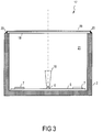
- FIG. 3 shows a lighting device 17, in which now in contrast to the embodiment of FIG. 2 instead of the lens a translucent lens 18 is present without significant visual effect.
- the cover plate 18 also has a transparent, electrically conductive coating 19, which in this example is connected to the housing by an electrically conductive adhesive 20, as a result of which the EMC shield or formation of the receiving space 21 through the housing 2 and the cover plate 18 or the coating 19 takes place.
- the coating 19 may, for example InO: Sn, ZnO: include AI or carbon nanotubes.
- the electrically conductive coating 19 may be applied to the inside or outside of the lens 18 without significant optical effect.
- the present invention is not limited to the present embodiments.
- the shape of the interior may be different, z. B. not square in cross-section, but arbitrarily shaped.
- the housing can also be designed as a heat sink and can be z. B. Identify cooling fins.
- the housing can also consist of metallized or metal-reinforced plastic or another suitable electrically conductive material or composite material.
- no single LED needs to be used as the light source, but it is also possible, for example, to use LED clusters of a plurality of differently colored LEDs whose colors are mixed together in an additive manner.
- the invention is not limited to LEDs, but may include other suitable light sources that require radiating elements to drive them, e.g. B. laser diodes.
- radiant elements can be accommodated, which are not needed to drive the LEDs, but for other purposes.
- the invention is not limited to an automotive application, but may include any suitable lighting application.
Landscapes
- Engineering & Computer Science (AREA)
- General Engineering & Computer Science (AREA)
- Physics & Mathematics (AREA)
- Microelectronics & Electronic Packaging (AREA)
- Optics & Photonics (AREA)
- Power Engineering (AREA)
- Non-Portable Lighting Devices Or Systems Thereof (AREA)
- Arrangement Of Elements, Cooling, Sealing, Or The Like Of Lighting Devices (AREA)
- Led Device Packages (AREA)
Description
Die Erfindung betrifft eine Beleuchtungsvorrichtung mit elektromagnetische Strahlung aussendenden Komponenten, insbesondere unter Verwendung von Leuchtdioden (LEDs), sowie eine Fahrzeugbeleuchtung.The invention relates to a lighting device with electromagnetic radiation emitting components, in particular using light emitting diodes (LEDs), as well as a vehicle lighting.
Bei einer Verwendung eines Schaltnetzteils zum Betreiben einer LED sendet das Schaltnetzteil typischerweise eine hochfrequente elektromagnetische Strahlung im Bereich von über 100 KHz aus und kann dadurch zu EMV-Problemen bei anderen elektronischen Komponenten führen. Dies ist insbesondere im Automobilbereich ein Problem, wo eine Vielzahl elektronischer Komponenten auf engstem Raum versammelt ist.When using a switched-mode power supply to drive an LED, the switched-mode power supply typically emits high-frequency electromagnetic radiation in the range of more than 100 kHz, which can lead to EMC problems with other electronic components. This is a problem, especially in the automotive sector, where a large number of electronic components are gathered in the smallest of spaces.
Zur Reduzierung der vom Schaltnetzteil ausgehenden EMV-Beeinflussung, insbesondere in Fahrzeugen, werden, neben einer Filterung der Aus- und Eingangsleitungen, Schaltnetzteile üblicherweise in einem eigenständigen, vollständig geschirmten Gehäuse betrieben. Dies ist aufwendig und voluminös und schwer.In order to reduce the EMI influence emanating from the switched-mode power supply, in particular in vehicles, in addition to filtering the output and input lines, switching power supplies are usually operated in an independent, completely shielded housing. This is elaborate and voluminous and heavy.
Es ist die Aufgabe der vorliegenden Erfindung, eine Möglichkeit zur kompakten, gewichts- und kostensparenden EMV-Schirmung von Schaltnetzteilen zu schaffen, insbesondere für Leuchtdioden insbesondere in Fahrzeugbau, speziell für Fahrzeugscheinwerfer.It is the object of the present invention to provide a way to compact, weight and cost-saving EMC shielding of switching power supplies, especially for light-emitting diodes, especially in vehicle, especially for vehicle headlights.
Diese Aufgabe wird mittels einer Beleuchtungsvorrichtung nach Anspruch 1 und einer Fahrzeugleuchte nach Anspruch 14 gelöst. Vorteilhafte Ausgestaltungen sind insbesondere den Unteransprüchen entnehmbar.This object is achieved by means of a lighting device according to claim 1 and a vehicle lamp according to
Die Beleuchtungsvorrichtung weist ein zumindest teilweise elektrisch leitfähiges Gehäuse auf, in dessen Innenraum mindestens eine Lichtquelle, insbesondere LED, und mindestens eine elektromagnetische Strahlung aussendende Schaltungskomponente zum Betreiben der mindestens einen Lichtquelle angeordnet sind. Weiterhin weist die Beleuchtungsvorrichtung eine elektrisch leitfähige Abdeckung zum Abdecken zumindest eines Teils der Schaltungskomponenten auf, wobei die Abdeckung und das Gehäuse elektrisch miteinander verbunden sind.The lighting device has an at least partially electrically conductive housing, in the interior of which at least a light source, in particular LED, and at least one electromagnetic radiation emitting circuit component for operating the at least one light source are arranged. Furthermore, the lighting device has an electrically conductive cover for covering at least part of the circuit components, wherein the cover and the housing are electrically connected to each other.
Die Abdeckung und das, üblicherweise geerdete, Gehäuse bilden dadurch einen Faradayschen Käfig, der elektromagnetische Strahlung abschirmt. Der Innenraum des Faradayschen Käfigs bildet einen geschirmten Aufnahmeraum zur Aufnahme der Schaltungskomponenten. Das Gehäuse braucht nur insoweit elektrisch leitfähig zu sein, als dass es den geschirmten Aufnahmeraum bilden kann.The cover and the usually grounded housing thereby form a Faraday cage which shields electromagnetic radiation. The interior of the Faraday cage forms a shielded receiving space for receiving the circuit components. The housing only needs to be electrically conductive insofar as it can form the shielded receiving space.
Typischerweise kann das Gehäuse eine offene Seite aufweisen, durch welche von der mindestens einen Lichtquelle emittiertes Licht nach Außen abgestrahlt wird.Typically, the housing may have an open side through which light emitted by the at least one light source is emitted to the outside.
Durch die Verwendung des die Lichtquelle aufnehmenden Gehäuses auch zur Unterbringung der abstrahlenden Komponenten kann auf ein gesondertes, vollständiges Gehäuse zur Schirmung der abstrahlenden Komponenten verzichtet werden. Dadurch ergeben sich kompakte Abmessungen sowie eine Gewichts- und Kostenersparnis.By using the light source accommodating housing also for accommodating the radiating components can be dispensed with a separate, complete housing for shielding the radiating components. This results in compact dimensions and weight and cost savings.
Zudem braucht auch die Platine, auf der die abstrahlenden Komponenten montiert sind, nicht besonders ausgeführt zu werden. Es ist die Verwendung einer einseitigen Platine mit minimaler Anzahl von Lagen möglich, was beispielsweise eine Kostenersparnis gegenüber einer Verwendung mehrlagiger, beidseitiger Platinen mit Masseplatte ermöglicht, welche ggf. ebenfalls zur Schirmung eingesetzt werden könnten.In addition, the board on which the radiating components are mounted, need not be carried out particularly. It is the use of a single-sided board with a minimum number of layers possible, which for example, a cost savings over using multi-layer, double-sided boards with ground plate allows, which could possibly also be used for shielding.
Die Beleuchtungsvorrichtung ist besonders gut zur Abschirmung von Komponenten geeignet, deren elektromagnetische Strahlung eine Frequenz von ca. 100 KHz oder mehr aufweist.The lighting device is particularly well suited for shielding components whose electromagnetic radiation has a frequency of about 100 KHz or more.
Die Abdeckung umfasst ein optisches Element zur Strahlführung des von der mindestens einen Lichtquelle emittierten Lichts in Form eines Reflektors, wobei die Lichtquelle durch die mittige Öffnung des Reflektors geführt ist.The cover comprises an optical element for the beam guidance of the light emitted by the at least one light source in the form of a reflector, wherein the light source is guided through the central opening of the reflector.
Dann weist der Reflektor bevorzugt eine Metallisierung auf, z. B. auf einer nichtleitenden Grundform.Then, the reflector preferably has a metallization, for. B. on a non-conductive basic form.
Es kann aber auch bevorzugt sein, wenn der Reflektor aus Metall hergestellt ist, z. B. im Tiefziehverfahren.However, it may also be preferred if the reflector is made of metal, for. B. in the deep drawing process.
Der Reflektor ist vorzugsweise elektrisch leitfähig an dem Gehäuse gehaltert, z. B. ohne weitere Befestigungsmittel.The reflector is preferably supported electrically conductive on the housing, for. B. without further fasteners.
Der Reflektor ist alternativ bevorzugt mittels eines elektrisch leitfähigen Klebers mit dem Gehäuse verbunden.Alternatively, the reflector is preferably connected to the housing by means of an electrically conductive adhesive.
Alternativ oder zusätzlich ist der Reflektor vorzugsweise mittels eines elektrisch leitfähigen mechanischen Verbindungselements mit dem Gehäuse verbunden, z. B. einer Metallklammer.Alternatively or additionally, the reflector is preferably connected by means of an electrically conductive mechanical connecting element with the housing, for. B. a metal clip.
Das optische Element weist vorzugsweise eine lichtdurchlässige, elektrisch leitfähige Beschichtung auf, wobei die Beschichtung speziell bevorzugt elektrisch mit dem Gehäuse verbunden ist.The optical element preferably has a light-transmitting, electrically conductive coating, wherein the coating is particularly preferably electrically connected to the housing.
Besonders bevorzugt ist es, wenn die Beschichtung mittels eines elektrisch leitfähigen Klebers elektrisch mit dem Gehäuse verbunden ist. Alternativ kann jede andere geeignete elektrisch leitfähige Verbindung verwendet werden, z. B. eine Lötverbindung.It is particularly preferred if the coating is electrically connected to the housing by means of an electrically conductive adhesive connected is. Alternatively, any other suitable electrically conductive compound may be used, e.g. B. a solder joint.
Alternativ oder zusätzlich kann es bevorzugt sein, wenn die Abdeckung ein lichtdurchlässiges, nicht strahlformendes Abschlusselement, insbesondere eine Abschlussscheibe, umfasst.Alternatively or additionally, it may be preferred if the cover comprises a light-transmitting, non-jet-forming closing element, in particular a cover disk.
Dann wird es bevorzugt, wenn das Abschlusselement eine lichtdurchlässige, elektrisch leitfähige Beschichtung aufweist, die elektrisch mit dem Gehäuse verbunden ist, insbesondere, wenn die Beschichtung mittels eines elektrisch leitfähigen Klebers elektrisch mit dem Gehäuse verbunden ist.It is then preferred if the terminating element has a light-transmitting, electrically conductive coating which is electrically connected to the housing, in particular if the coating is electrically connected to the housing by means of an electrically conductive adhesive.
Bevorzugt wird eine Beleuchtungsvorrichtung, bei der das Gehäuse aus Metall hergestellt ist.Preferred is a lighting device in which the housing is made of metal.
Alternativ kann eine Beleuchtungsvorrichtung bevorzugt sein, bei der das Gehäuse aus leitfähigem, insbesondere metallisiertem, Kunststoff hergestellt ist.Alternatively, a lighting device may be preferred in which the housing is made of conductive, in particular metallized, plastic.
Besonders bevorzugt wird eine Beleuchtungsvorrichtung, bei der das Gehäuse als Kühlkörper ausgebildet ist, z. B. durch Vorsehen von Kühlrippen, aber auch ohne Kühlrippen.Particularly preferred is a lighting device in which the housing is formed as a heat sink, for. B. by providing cooling fins, but also without cooling fins.
Bevorzugt wird ferner eine Beleuchtungsvorrichtung, bei der die mindestens eine elektromagnetische Strahlung aussendende Schaltungskomponente mit mindestens einem elektronischen Filterglied zur Reduzierung einer elektromagnetischen Abstrahlung elektrischer Zuleitungen verbunden ist.Furthermore, a lighting device in which the at least one electromagnetic radiation-emitting circuit component is connected to at least one electronic filter element for reducing electromagnetic radiation of electrical supply lines is preferred.
Insbesondere bevorzugt ist eine Verwendung einer solchen Beleuchtungsvorrichtung in einem Fahrzeug, z. B. als Scheinwerfer, Blinker, Rückleuchte, Bremsleuchte, Seitenleuchte, Abblendleuchte, und so weiter.Particularly preferred is a use of such a lighting device in a vehicle, for. B. as a headlight, turn signal, tail light, brake light, side light, low beam, and so on.
Die mindestens eine LED kann eine einzelne LED sein oder mehrere LEDs umfassen. Die mehreren LEDs können in Gruppen angeordnet sein, sog. LED-Clustern. Die LEDs können einfarbig oder verschiedenfarbig sein. Insbesondere kann das LED-Cluster mehrere verschiedenfarbige LEDs aufweisen, vorzugsweise geeignet für eine weiße additive Farbmischung, z. B. der Art RGB, RRGB, RGGB usw. Die LEDs können spektral rein oder gemischt abstrahlen. Auch sind LEDs umfasst, die IR- oder UV-Licht abstrahlen. Auch umfasst sind LEDs mit wellenlängenumwandelndem Material, z. B. auf Phosphorbasis, z. B. zur Umwandlung von blauem in gelbes Licht.The at least one LED may be a single LED or comprise multiple LEDs. The multiple LEDs can be arranged in groups, so-called LED clusters. The LEDs can be monochrome or different colors. In particular, the LED cluster can have a plurality of differently colored LEDs, preferably suitable for white additive color mixing, for. B. the type RGB, RRGB, RGGB, etc. The LEDs can spectrally pure or mixed radiate. Also includes LEDs that emit IR or UV light. Also included are LEDs with wavelength-converting material, e.g. B. based on phosphorus, z. B. to convert from blue to yellow light.
In einem folgenden Ausführungsbeispiel wird die Erfindung schematisch näher ausgeführt. Dabei können gleiche Bezugsziffern gleiche oder funktional gleiche oder ähnliche Elemente durch mehrere Figuren hindurch bezeichnen.
- FIG 1
- zeigt als Querschnittsansicht in Seitenansicht eine erfindungsgemäße Leuchtvorrichtung;
- FIG 2
- zeigt als Querschnittsansicht in Seitenansicht eine weitere Leuchtvorrichtung;
- FIG 3
- zeigt als Querschnittsansicht in Seitenansicht noch eine weitere Leuchtvorrichtung.
- FIG. 1
- shows a cross-sectional view in side view of a lighting device according to the invention;
- FIG. 2
- shows a cross-sectional view in side view of a further lighting device;
- FIG. 3
- shows a cross-sectional view in side view yet another lighting device.
Auf die Ränder der Öffnung 4 ist ein elektrisch leitender Reflektor 8 aufgesetzt, der eine mittige Öffnung (ohne Bezugszeichen) aufweist, durch welche die LED 6 geführt ist. Mittels des Reflektors 8 wird Licht, das von der LED 6 auf diesen abgestrahlt wird, durch die Öffnung 4 symmetrisch zur optischen Achse O nach Außen abgestrahlt. Der Reflektor 8 deckt die Komponenten 7 des Schaltnetzteils ab und schafft dadurch zusammen mit dem Gehäuse 2 einen Aufnahmeraum 9 für diese Komponenten 7. Ferner sind der Reflektor 8 und das Gehäuse 2 elektrisch durch einen elektrisch leitfähigen Kleber miteinander verbunden, der sich an der Grenzfläche 10 zwischen Reflektor 8 und Gehäuse 2 befindet.On the edges of the
Durch die elektrische Verbindung bzw. Masseanbindung zwischen Reflektor 8 und Gehäuse 2 wird ein Faradayscher Käfig gebildet, der elektromagnetische Strahlung daran hindert, aus dem Aufnahmeraum 9 hinaus oder in diesen hinein zu laufen. Dabei ist die mittige Öffnung im Reflektor 8 zur Durchführung der LED 6 für typische Frequenzen ca. ≥ 100 KHz, wie sie von Schaltnetzteilen erzeugt werden, unschädlich.As a result of the electrical connection or ground connection between the
Im gezeigten Beispiel besteht der Reflektor 8 aus Metall, ggf. mit Schutzschichten, und ist im Tiefziehverfahren hergestellt.In the example shown, the
Alternativ ist das Gehäuse nicht rotationssymmetrisch ausgeführt, sondern länglich, wobei dann in
Alternativ kann der Reflektor eine mit dem Gehäuse geeignet verbundene, insbesondere großflächige Metallisierung aufweisen, z. B. aufgebracht auf einen Kunststoff-Grundkörper. Diese Metallisierung kann dann auch zur Lichtreflexion verwendet werdenAlternatively, the reflector may have a suitably connected to the housing, in particular large-scale metallization, for. B. applied to a plastic body. This metallization can then also be used for light reflection
Als Massenanbindung des Reflektors an das Gehäuse kann eventuell bereits seine mechanische Halterung am Gehäuse, also ohne Haftverbindung, ausreichen. Alternativ oder zusätzlich kann die Masseanbindung beispielsweise durch eine mechanische Spannvorrichtung aus Metall gegeben sein.As a mass connection of the reflector to the housing may possibly already its mechanical support on the housing, ie without adhesive connection sufficient. Alternatively or additionally, the ground connection can be given for example by a mechanical tensioning device made of metal.
Auch hier braucht das Gehäuse nicht rotationssymmetrisch ausgebildet zu sein, sondern kann beispielsweise auch länglich ausgeführt sein, insbesondere bei Verwendung mehrerer LEDs.Again, the housing need not be rotationally symmetrical, but may for example also be elongated, especially when using multiple LEDs.
Für die EMV-gerechte Abschirmung der elektrischen Zuleitungen (ohne Abbildung) zur Leuchtvorrichtung (LED-Modul) sind in der Treiberelektronik 7 elektronische Filterglieder integriert, die eine Abschirmung der Zuleitungskabel unnötig machen. Ansonsten ist auch die Verwendung eines geschirmten Zuleitungskabels möglich, welches an beiden Enden elektrisch leitfähig mit den entsprechenden Gegensteckern verbunden ist.For EMC-compliant shielding of the electrical leads (not shown) to the lighting device (LED module) 7 electronic filter elements are integrated in the driver electronics, which make a shielding of the supply cable unnecessary. Otherwise, the use of a shielded supply cable is possible, which is electrically conductively connected at both ends with the corresponding mating connectors.
Selbstverständlich ist die vorliegende Erfindung nicht auf die vorliegenden Ausführungsbeispiele beschränkt. So kann die Form des Innenraums unterschiedlich ausgeprägt sein, z. B. nicht viereckig im Querschnitt, sondern beliebig geformt.Of course, the present invention is not limited to the present embodiments. Thus, the shape of the interior may be different, z. B. not square in cross-section, but arbitrarily shaped.
Das Gehäuse kann auch als Kühlkörper ausgeführt sein und kann dazu z. B. Kühlrippen ausweisen.The housing can also be designed as a heat sink and can be z. B. Identify cooling fins.
Das Gehäuse kann beispielsweise statt aus Vollmetall auch aus metallisiertem oder metallbewehrtem Kunststoff oder einem anderen geeigneten elektrisch leitfähigen Material oder Materialverbund bestehen.For example, instead of being made of solid metal, the housing can also consist of metallized or metal-reinforced plastic or another suitable electrically conductive material or composite material.
Auch braucht ferner keine einzelne LED als Lichtquelle verwendet zu werden, sondern es können beispielsweise auch LED-Cluster aus mehreren verschiedenfarbigen LEDs verwendet werden, deren Farben additiv zusammengemischt werden.Furthermore, furthermore, no single LED needs to be used as the light source, but it is also possible, for example, to use LED clusters of a plurality of differently colored LEDs whose colors are mixed together in an additive manner.
Allgemein ist die Erfindung nicht auf LEDs beschränkt, sondern kann auch andere geeignete Lichtquellen umfassen, die abstrahlende Elemente zu ihrer Ansteuerung benötigen, z. B. Laserdioden.Generally, the invention is not limited to LEDs, but may include other suitable light sources that require radiating elements to drive them, e.g. B. laser diodes.
Auch können im Aufnahmeraum strahlende Elemente untergebracht werden, die nicht zur Ansteuerung der LEDs benötigt werden, sondern für andere Zwecke.Also in the recording room radiant elements can be accommodated, which are not needed to drive the LEDs, but for other purposes.
Die Erfindung ist nicht auf eine Anwendung im Fahrzeugbau beschränkt, sondern kann alle geeigneten Beleuchtungsanwendungen umfassen.The invention is not limited to an automotive application, but may include any suitable lighting application.
- 11
- Beleuchtungsvorrichtunglighting device
- 22
- Gehäusecasing
- 33
- Innenrauminner space
- 44
- Öffnungopening
- 55
- Platinecircuit board
- 66
- LEDLED
- 77
- Komponenten eines SchaltnetzteilsComponents of a switching power supply
- 88th
- Reflektorreflector
- 99
- Aufnahmeraumaccommodation space
- 1010
- Grenzflächeinterface
- 1111
- Beleuchtungsvorrichtunglighting device
- 1212
- Projektionslinseprojection lens
- 1313
- Beschichtungcoating
- 1414
- Klebstoffadhesive
- 1515
- Aufnahmeraumaccommodation space
- 1616
- Primäroptikprimary optics
- 1717
- Beleuchtungsvorrichtunglighting device
- 1818
- Abschlussscheibelens
- 1919
- Beschichtungcoating
- 2020
- Klebstoffadhesive
- 2121
- Aufnahmeraumaccommodation space
- OO
- optische Achseoptical axis
Claims (14)
- Lighting apparatus (1) with an electrically conductive housing (2), in whose interior (3) at least one light source (6), in particular an LED, and at least one electromagnetic radiation-emitting circuit component (7) for operating the at least one light source (6) are arranged, and with an electrically conductive cover (8; 12, 13; 18, 19) for covering the circuit components (7), the cover (8; 12, 13; 18, 19) and the housing (2) being electrically connected to one another, wherein the cover (8) comprises an optical element for guiding the beam of light emitted by the light source (6) in the form of a reflector (8) and wherein the light source (6) is passed through a central opening of the reflector (8).
- Lighting apparatus (1) according to Claim 1, in which the electromagnetic radiation has a frequency of approximately 100 kHz or more.
- Lighting apparatus (1) according to one of the preceding claims, in which the reflector has a metal plating.
- Lighting apparatus (1) according to one of Claims 1 to 2, in which the reflector (8) is produced from metal.
- Lighting apparatus (1) according to one of the preceding claims, in which the reflector (8) is held in an electrically conductive manner on the housing (2).
- Lighting apparatus (1) according to one of the preceding claims, in which the reflector (8) is connected to the housing (2) by means of an electrically conductive adhesive.
- Lighting apparatus (1) according to one of the preceding claims, in which the reflector is connected to the housing (2) by means of an electrically conductive, mechanical connecting element.
- Lighting apparatus (1) according to one of the preceding claims, in which the housing (2) is produced from metal.
- Lighting apparatus (1) according to one of Claims 1 to 7, in which the housing is produced from conductive, in particular metal-plated, plastic.
- Lighting apparatus (1) according to one of the preceding claims, in which the housing is in the form of a heat sink.
- Lighting apparatus (1) according to one of the preceding claims, in which the at least one electromagnetic radiation-emitting circuit component (7) is connected to at least one electronic filter element for reducing emission of electromagnetic radiation from electrical feed lines.
- Lighting apparatus (1) according to one of the preceding claims, in which the at least one light source has at least one LED (6).
- Lighting apparatus (1) according to Claim 12, in which the at least one electromagnetic radiation-emitting circuit component (7) has at least one component of a switched-mode power supply.
- Vehicle lighting system with a lighting apparatus (1) according to one of the preceding claims.
Applications Claiming Priority (2)
| Application Number | Priority Date | Filing Date | Title |
|---|---|---|---|
| DE102007037822A DE102007037822A1 (en) | 2007-08-10 | 2007-08-10 | lighting device |
| PCT/EP2008/006570 WO2009021694A1 (en) | 2007-08-10 | 2008-08-08 | Lighting apparatus |
Publications (2)
| Publication Number | Publication Date |
|---|---|
| EP2179217A1 EP2179217A1 (en) | 2010-04-28 |
| EP2179217B1 true EP2179217B1 (en) | 2019-03-13 |
Family
ID=39944323
Family Applications (1)
| Application Number | Title | Priority Date | Filing Date |
|---|---|---|---|
| EP08785463.4A Active EP2179217B1 (en) | 2007-08-10 | 2008-08-08 | Lighting apparatus |
Country Status (6)
| Country | Link |
|---|---|
| US (1) | US8602620B2 (en) |
| EP (1) | EP2179217B1 (en) |
| JP (1) | JP5416102B2 (en) |
| CN (1) | CN101688659B (en) |
| DE (1) | DE102007037822A1 (en) |
| WO (1) | WO2009021694A1 (en) |
Families Citing this family (25)
| Publication number | Priority date | Publication date | Assignee | Title |
|---|---|---|---|---|
| JP5288161B2 (en) * | 2008-02-14 | 2013-09-11 | 東芝ライテック株式会社 | Light emitting module and lighting device |
| DE102009047765A1 (en) * | 2009-12-10 | 2011-06-16 | Ifm Electronic Gmbh | High frequency modulated lighting for photonic mixer device camera installed in motor vehicle, has opening formed in housing at region of light sources, and metal plating that controls electromagnetic emission |
| CN102762920B (en) * | 2010-02-11 | 2015-04-08 | 帝斯曼知识产权资产管理有限公司 | Led lighting device |
| DE202010007032U1 (en) * | 2010-04-09 | 2011-08-09 | Tridonic Jennersdorf Gmbh | LED module for spotlights |
| EP2386792B1 (en) * | 2010-05-12 | 2013-09-11 | Zizala Lichtsysteme GmbH | LED light module |
| WO2012081258A1 (en) * | 2010-12-16 | 2012-06-21 | パナソニック株式会社 | Illuminating light source and illuminating device |
| RU2649891C2 (en) * | 2012-02-03 | 2018-04-05 | Филипс Лайтинг Холдинг Б.В. | Lighting driver and body that has a internal electromagnetic screen layer for direct connection with earth connection |
| DE102012202354A1 (en) | 2012-02-16 | 2013-08-22 | Osram Gmbh | light module |
| JP5690764B2 (en) * | 2012-03-06 | 2015-03-25 | 株式会社ホンダアクセス | Lighting device |
| DE102012204786A1 (en) * | 2012-03-26 | 2013-09-26 | Osram Gmbh | LIGHTING DEVICE WITH FLUORESCENT BODY ON COOLING BODY |
| US20130335980A1 (en) * | 2012-06-13 | 2013-12-19 | Panasonic Corporation | Light emitting device and lighting fixture |
| US9696012B2 (en) * | 2012-10-04 | 2017-07-04 | Guardian Industries Corp. | Embedded LED assembly with optional beam steering optical element, and associated products, and/or methods |
| JP2014149978A (en) * | 2013-02-01 | 2014-08-21 | Ichikoh Ind Ltd | Vehicular lamp |
| AT513747B1 (en) | 2013-02-28 | 2014-07-15 | Mikroelektronik Ges Mit Beschränkter Haftung Ab | Assembly process for circuit carriers and circuit carriers |
| JP6441652B2 (en) * | 2014-02-12 | 2018-12-19 | 株式会社小糸製作所 | Vehicle lighting |
| FR3022608B1 (en) * | 2014-06-19 | 2018-07-20 | Psa Automobiles Sa. | LIGHTING AND / OR SIGNALING DEVICE GENERATING A HOMOGENEOUS LIGHT ON A SCREEN |
| DE102014009594A1 (en) * | 2014-06-27 | 2015-12-31 | Audi Ag | Lighting device for a motor vehicle with a safety device for detecting fault conditions and method for detecting fault conditions |
| FR3032516B1 (en) | 2015-02-06 | 2021-04-16 | Valeo Vision | LUMINOUS MODULE REFLECTOR DEVICE WITH ELECTROMAGNETIC SHIELDING |
| KR101755783B1 (en) * | 2015-03-05 | 2017-07-20 | 현대자동차주식회사 | Laser optical system for in vehicle |
| US10100998B2 (en) * | 2015-05-26 | 2018-10-16 | The Boeing Company | Electrically shielded lighting apparatus |
| FR3037730A1 (en) * | 2015-06-22 | 2016-12-23 | Valeo Vision | LUMINOUS DEVICE OF A MOTOR VEHICLE WITH LIMITED ELECTROMAGNETIC RADIATION |
| FR3047796B1 (en) * | 2016-02-15 | 2019-05-24 | Valeo Vision Belgique | LUMINOUS DEVICE HOUSING OF A MOTOR VEHICLE |
| DE102017115593A1 (en) * | 2017-07-12 | 2019-01-17 | HELLA GmbH & Co. KGaA | Lighting device for vehicles |
| FR3090076A1 (en) * | 2018-12-12 | 2020-06-19 | Valeo Vision Belgique | Lighting device comprising an electronic circuit protected by a Faraday cage |
| WO2022152553A1 (en) * | 2021-01-12 | 2022-07-21 | Signify Holding B.V. | Lighting arrangement for illumination and disinfection lighting |
Family Cites Families (27)
| Publication number | Priority date | Publication date | Assignee | Title |
|---|---|---|---|---|
| DE8205219U1 (en) | 1982-02-25 | 1982-05-19 | Walz, Alfred, Prof. Dr.-Ing., 7830 Emmendingen | WORKPLACE LIGHT |
| DE3701789A1 (en) | 1987-01-22 | 1988-08-04 | Siemens Ag | Indicating unit (display unit) |
| JPH03136938A (en) | 1989-10-23 | 1991-06-11 | Nissan Motor Co Ltd | Discharge lamp head lamp device for vehicle |
| US5006763A (en) * | 1990-03-12 | 1991-04-09 | General Electric Company | Luminaire for an electrodeless high intensity discharge lamp with electromagnetic interference shielding |
| JP2626155B2 (en) * | 1990-04-20 | 1997-07-02 | 日産自動車株式会社 | Vehicle discharge lamp headlamp |
| US5581157A (en) * | 1992-05-20 | 1996-12-03 | Diablo Research Corporation | Discharge lamps and methods for making discharge lamps |
| DE4310307B4 (en) * | 1993-03-30 | 2004-10-14 | Robert Bosch Gmbh | Headlights for vehicles |
| CN1096103C (en) * | 1995-05-24 | 2002-12-11 | 皇家菲利浦电子有限公司 | Lighting unit and electrodeless low-pressure discharge lamp, and discharge vessel for use in said lighting unit |
| US5882108A (en) * | 1995-10-12 | 1999-03-16 | Valeo Sylvania L.L.C. | Lighting with EMI shielding |
| JP3195215B2 (en) * | 1995-12-28 | 2001-08-06 | 株式会社小糸製作所 | Automotive headlamp |
| AU7619996A (en) * | 1996-01-11 | 1997-08-01 | Patent-Treuhand-Gesellschaft Fur Elektrische Gluhlampen Mbh | Electric lamp with uncemented base |
| JP3854421B2 (en) * | 1999-02-23 | 2006-12-06 | 株式会社小糸製作所 | Vehicle lamp having a discharge bulb |
| JP4106801B2 (en) * | 1999-03-24 | 2008-06-25 | 松下電工株式会社 | Fuel cell power generation system |
| CN1334591A (en) * | 2000-07-18 | 2002-02-06 | 戴培钧 | High-frequency induced electrodeless electronic fluorescent lamp |
| DE10308866A1 (en) * | 2003-02-28 | 2004-09-09 | Osram Opto Semiconductors Gmbh | Lighting module and method for its production |
| DE10329078A1 (en) | 2003-06-27 | 2005-01-20 | Osram Opto Semiconductors Gmbh | Illumination module especially for air-traffic signaling or warning lamp, has LED encapsulated in housing with light-emission window |
| JP3987485B2 (en) | 2003-12-25 | 2007-10-10 | セイコーエプソン株式会社 | Light source device and projector |
| DE202004003793U1 (en) | 2004-03-11 | 2004-05-13 | Hella Kg Hueck & Co. | Light emitting diode (LED) assembly for fitting into cars, comprises cooler for dissipating waste heat and directly supporting LEDs and electronic components |
| JP2006184347A (en) | 2004-12-27 | 2006-07-13 | Casio Comput Co Ltd | Image display device |
| JP2006302712A (en) * | 2005-04-21 | 2006-11-02 | Koito Mfg Co Ltd | Vehicle head-lamp |
| JP4656997B2 (en) * | 2005-04-21 | 2011-03-23 | 株式会社小糸製作所 | Vehicle lighting |
| JP2006302713A (en) * | 2005-04-21 | 2006-11-02 | Koito Mfg Co Ltd | Vehicle head-lamp |
| JP4471169B2 (en) * | 2005-04-21 | 2010-06-02 | 株式会社小糸製作所 | Projector type vehicle lamp unit |
| JP4703375B2 (en) * | 2005-11-08 | 2011-06-15 | 株式会社小糸製作所 | Interior lighting |
| DE102006001981A1 (en) | 2006-01-16 | 2007-08-02 | CFL Licht & Design GbR (vertretungsberechtigte Gesellschafter: Wilfried Böhm | Light strip for e.g. decorative illumination system, has base firmly connected with metal section, such that narrow side of base is arranged on open side of section, where side surfaces and side are laid in section without distance |
| JP4500273B2 (en) * | 2006-01-31 | 2010-07-14 | 株式会社小糸製作所 | Vehicle headlamp |
| JP4595914B2 (en) * | 2006-10-03 | 2010-12-08 | パナソニック電工株式会社 | LED lamp |
-
2007
- 2007-08-10 DE DE102007037822A patent/DE102007037822A1/en not_active Withdrawn
-
2008
- 2008-08-08 JP JP2010512612A patent/JP5416102B2/en active Active
- 2008-08-08 EP EP08785463.4A patent/EP2179217B1/en active Active
- 2008-08-08 WO PCT/EP2008/006570 patent/WO2009021694A1/en active Application Filing
- 2008-08-08 US US12/672,714 patent/US8602620B2/en active Active
- 2008-08-08 CN CN2008800209753A patent/CN101688659B/en active Active
Non-Patent Citations (1)
| Title |
|---|
| None * |
Also Published As
| Publication number | Publication date |
|---|---|
| DE102007037822A1 (en) | 2009-02-12 |
| JP5416102B2 (en) | 2014-02-12 |
| CN101688659A (en) | 2010-03-31 |
| US8602620B2 (en) | 2013-12-10 |
| WO2009021694A1 (en) | 2009-02-19 |
| US20110038172A1 (en) | 2011-02-17 |
| CN101688659B (en) | 2013-01-23 |
| EP2179217A1 (en) | 2010-04-28 |
| JP2010531037A (en) | 2010-09-16 |
Similar Documents
| Publication | Publication Date | Title |
|---|---|---|
| EP2179217B1 (en) | Lighting apparatus | |
| DE102007043903A1 (en) | Luminous device | |
| DE102007033706B4 (en) | Vehicle light device with a three-dimensional multicolor intermediate lens | |
| EP2556287B1 (en) | Light emission arrangement having a plurality of light sources and a transparent light emission element | |
| DE102010012137A1 (en) | Lighting device i.e. headlight for motor vehicle, has carrier controlling and/or supplying current to LEDs, where one of LEDs is arranged at side of carrier, and other LED is arranged at another side of carrier | |
| DE102014221815A1 (en) | Lighting device and headlights for a motor vehicle | |
| EP1955895B1 (en) | Lighting device for a vehicle with a LED-modul | |
| DE102009047765A1 (en) | High frequency modulated lighting for photonic mixer device camera installed in motor vehicle, has opening formed in housing at region of light sources, and metal plating that controls electromagnetic emission | |
| DE202012104567U1 (en) | lighting arrangement | |
| DE102005042611A1 (en) | Lighting device for a vehicle with two groups of light sources for at least two light functions | |
| WO2019029977A1 (en) | Luminaire having two light sources and an optic | |
| WO2015040240A1 (en) | Lamp | |
| DE102018211056A1 (en) | Lighting unit for a motor vehicle | |
| EP3244126A1 (en) | Lamp with at least one light emitting diode (led), in particular front headlamp with daytime running lights for a motor vehicle | |
| DE102007056270B4 (en) | Lighting unit with an LED light source | |
| DE102010055329A1 (en) | Lighting device for vehicle, has light module, which is arranged inside housing and has light coupling surface, over which light beams of light source are injected | |
| EP2216588B1 (en) | Reflector component system | |
| DE102008004483A1 (en) | Light e.g. front light, for motor vehicle, has illuminants i.e. LED, connected to array by flexible sheet flat conductor, inserted into light emitting openings from side of carrier part and fixed by fixing unit | |
| DE102012007228A1 (en) | Reflector arrangement for illumination device e.g. headlight, of vehicle, has reflection surfaces reflecting light radiation in direction of reflector element that is arranged at outer side of main radiation characteristic of light source | |
| DE102012109492A1 (en) | Illumination unit for motor vehicle, has mounting body formed as cooling body, and anti-glare element arranged at reflector for delimiting radiation area, where reflector and anti-glare element are integrally formed as functional element | |
| DE102012103309A1 (en) | Light guiding device for light module of headlight, has light guiding body with light guiding base, which extends over main-light emitting surface and has auxiliary light-emitting surface for laterally directed light output | |
| DE102012218785A1 (en) | LAMP | |
| DE102010060424A1 (en) | Device for lighting an environment | |
| DE102008011818A1 (en) | Festoon lamp and method of making a festoon lamp | |
| DE202010008431U1 (en) | Flexible lighting arrangement |
Legal Events
| Date | Code | Title | Description |
|---|---|---|---|
| PUAI | Public reference made under article 153(3) epc to a published international application that has entered the european phase |
Free format text: ORIGINAL CODE: 0009012 |
|
| 17P | Request for examination filed |
Effective date: 20100310 |
|
| AK | Designated contracting states |
Kind code of ref document: A1 Designated state(s): AT BE BG CH CY CZ DE DK EE ES FI FR GB GR HR HU IE IS IT LI LT LU LV MC MT NL NO PL PT RO SE SI SK TR |
|
| AX | Request for extension of the european patent |
Extension state: AL BA MK RS |
|
| RIN1 | Information on inventor provided before grant (corrected) |
Inventor name: REINERS, THOMAS Inventor name: VOLLMER, RALF |
|
| DAX | Request for extension of the european patent (deleted) | ||
| RAP1 | Party data changed (applicant data changed or rights of an application transferred) |
Owner name: OSRAM AG |
|
| 17Q | First examination report despatched |
Effective date: 20121130 |
|
| RAP1 | Party data changed (applicant data changed or rights of an application transferred) |
Owner name: OSRAM GMBH |
|
| RAP1 | Party data changed (applicant data changed or rights of an application transferred) |
Owner name: OSRAM GMBH |
|
| REG | Reference to a national code |
Ref country code: DE Ref legal event code: R079 Ref document number: 502008016647 Country of ref document: DE Free format text: PREVIOUS MAIN CLASS: F21V0025000000 Ipc: F21V0023000000 |
|
| GRAP | Despatch of communication of intention to grant a patent |
Free format text: ORIGINAL CODE: EPIDOSNIGR1 |
|
| STAA | Information on the status of an ep patent application or granted ep patent |
Free format text: STATUS: GRANT OF PATENT IS INTENDED |
|
| RIC1 | Information provided on ipc code assigned before grant |
Ipc: F21V 25/00 20060101ALI20180514BHEP Ipc: F21S 41/00 20180101ALI20180514BHEP Ipc: F21V 23/00 20060101AFI20180514BHEP Ipc: F21V 3/04 20060101ALI20180514BHEP |
|
| INTG | Intention to grant announced |
Effective date: 20180606 |
|
| RIN1 | Information on inventor provided before grant (corrected) |
Inventor name: REINERS, THOMAS Inventor name: VOLLMER, RALPH |
|
| GRAJ | Information related to disapproval of communication of intention to grant by the applicant or resumption of examination proceedings by the epo deleted |
Free format text: ORIGINAL CODE: EPIDOSDIGR1 |
|
| STAA | Information on the status of an ep patent application or granted ep patent |
Free format text: STATUS: EXAMINATION IS IN PROGRESS |
|
| GRAS | Grant fee paid |
Free format text: ORIGINAL CODE: EPIDOSNIGR3 |
|
| STAA | Information on the status of an ep patent application or granted ep patent |
Free format text: STATUS: GRANT OF PATENT IS INTENDED |
|
| GRAP | Despatch of communication of intention to grant a patent |
Free format text: ORIGINAL CODE: EPIDOSNIGR1 |
|
| INTC | Intention to grant announced (deleted) | ||
| INTG | Intention to grant announced |
Effective date: 20181102 |
|
| GRAA | (expected) grant |
Free format text: ORIGINAL CODE: 0009210 |
|
| STAA | Information on the status of an ep patent application or granted ep patent |
Free format text: STATUS: THE PATENT HAS BEEN GRANTED |
|
| RIC1 | Information provided on ipc code assigned before grant |
Ipc: F21V 23/00 20150101AFI20180514BHEP Ipc: F21S 41/00 20180101ALI20180514BHEP Ipc: F21V 25/00 20060101ALI20180514BHEP Ipc: F21V 3/04 20180101ALI20180514BHEP |
|
| AK | Designated contracting states |
Kind code of ref document: B1 Designated state(s): AT BE BG CH CY CZ DE DK EE ES FI FR GB GR HR HU IE IS IT LI LT LU LV MC MT NL NO PL PT RO SE SI SK TR |
|
| REG | Reference to a national code |
Ref country code: GB Ref legal event code: FG4D Free format text: NOT ENGLISH |
|
| REG | Reference to a national code |
Ref country code: CH Ref legal event code: EP Ref country code: AT Ref legal event code: REF Ref document number: 1108205 Country of ref document: AT Kind code of ref document: T Effective date: 20190315 |
|
| REG | Reference to a national code |
Ref country code: IE Ref legal event code: FG4D Free format text: LANGUAGE OF EP DOCUMENT: GERMAN |
|
| REG | Reference to a national code |
Ref country code: DE Ref legal event code: R096 Ref document number: 502008016647 Country of ref document: DE |
|
| REG | Reference to a national code |
Ref country code: NL Ref legal event code: MP Effective date: 20190313 |
|
| REG | Reference to a national code |
Ref country code: LT Ref legal event code: MG4D |
|
| PG25 | Lapsed in a contracting state [announced via postgrant information from national office to epo] |
Ref country code: NO Free format text: LAPSE BECAUSE OF FAILURE TO SUBMIT A TRANSLATION OF THE DESCRIPTION OR TO PAY THE FEE WITHIN THE PRESCRIBED TIME-LIMIT Effective date: 20190613 Ref country code: FI Free format text: LAPSE BECAUSE OF FAILURE TO SUBMIT A TRANSLATION OF THE DESCRIPTION OR TO PAY THE FEE WITHIN THE PRESCRIBED TIME-LIMIT Effective date: 20190313 Ref country code: SE Free format text: LAPSE BECAUSE OF FAILURE TO SUBMIT A TRANSLATION OF THE DESCRIPTION OR TO PAY THE FEE WITHIN THE PRESCRIBED TIME-LIMIT Effective date: 20190313 Ref country code: LT Free format text: LAPSE BECAUSE OF FAILURE TO SUBMIT A TRANSLATION OF THE DESCRIPTION OR TO PAY THE FEE WITHIN THE PRESCRIBED TIME-LIMIT Effective date: 20190313 |
|
| PG25 | Lapsed in a contracting state [announced via postgrant information from national office to epo] |
Ref country code: GR Free format text: LAPSE BECAUSE OF FAILURE TO SUBMIT A TRANSLATION OF THE DESCRIPTION OR TO PAY THE FEE WITHIN THE PRESCRIBED TIME-LIMIT Effective date: 20190614 Ref country code: HR Free format text: LAPSE BECAUSE OF FAILURE TO SUBMIT A TRANSLATION OF THE DESCRIPTION OR TO PAY THE FEE WITHIN THE PRESCRIBED TIME-LIMIT Effective date: 20190313 Ref country code: NL Free format text: LAPSE BECAUSE OF FAILURE TO SUBMIT A TRANSLATION OF THE DESCRIPTION OR TO PAY THE FEE WITHIN THE PRESCRIBED TIME-LIMIT Effective date: 20190313 Ref country code: BG Free format text: LAPSE BECAUSE OF FAILURE TO SUBMIT A TRANSLATION OF THE DESCRIPTION OR TO PAY THE FEE WITHIN THE PRESCRIBED TIME-LIMIT Effective date: 20190613 Ref country code: LV Free format text: LAPSE BECAUSE OF FAILURE TO SUBMIT A TRANSLATION OF THE DESCRIPTION OR TO PAY THE FEE WITHIN THE PRESCRIBED TIME-LIMIT Effective date: 20190313 |
|
| PG25 | Lapsed in a contracting state [announced via postgrant information from national office to epo] |
Ref country code: SK Free format text: LAPSE BECAUSE OF FAILURE TO SUBMIT A TRANSLATION OF THE DESCRIPTION OR TO PAY THE FEE WITHIN THE PRESCRIBED TIME-LIMIT Effective date: 20190313 Ref country code: RO Free format text: LAPSE BECAUSE OF FAILURE TO SUBMIT A TRANSLATION OF THE DESCRIPTION OR TO PAY THE FEE WITHIN THE PRESCRIBED TIME-LIMIT Effective date: 20190313 Ref country code: EE Free format text: LAPSE BECAUSE OF FAILURE TO SUBMIT A TRANSLATION OF THE DESCRIPTION OR TO PAY THE FEE WITHIN THE PRESCRIBED TIME-LIMIT Effective date: 20190313 Ref country code: IT Free format text: LAPSE BECAUSE OF FAILURE TO SUBMIT A TRANSLATION OF THE DESCRIPTION OR TO PAY THE FEE WITHIN THE PRESCRIBED TIME-LIMIT Effective date: 20190313 Ref country code: ES Free format text: LAPSE BECAUSE OF FAILURE TO SUBMIT A TRANSLATION OF THE DESCRIPTION OR TO PAY THE FEE WITHIN THE PRESCRIBED TIME-LIMIT Effective date: 20190313 Ref country code: PT Free format text: LAPSE BECAUSE OF FAILURE TO SUBMIT A TRANSLATION OF THE DESCRIPTION OR TO PAY THE FEE WITHIN THE PRESCRIBED TIME-LIMIT Effective date: 20190713 Ref country code: CZ Free format text: LAPSE BECAUSE OF FAILURE TO SUBMIT A TRANSLATION OF THE DESCRIPTION OR TO PAY THE FEE WITHIN THE PRESCRIBED TIME-LIMIT Effective date: 20190313 |
|
| PG25 | Lapsed in a contracting state [announced via postgrant information from national office to epo] |
Ref country code: PL Free format text: LAPSE BECAUSE OF FAILURE TO SUBMIT A TRANSLATION OF THE DESCRIPTION OR TO PAY THE FEE WITHIN THE PRESCRIBED TIME-LIMIT Effective date: 20190313 |
|
| REG | Reference to a national code |
Ref country code: DE Ref legal event code: R097 Ref document number: 502008016647 Country of ref document: DE |
|
| PG25 | Lapsed in a contracting state [announced via postgrant information from national office to epo] |
Ref country code: IS Free format text: LAPSE BECAUSE OF FAILURE TO SUBMIT A TRANSLATION OF THE DESCRIPTION OR TO PAY THE FEE WITHIN THE PRESCRIBED TIME-LIMIT Effective date: 20190713 |
|
| PLBE | No opposition filed within time limit |
Free format text: ORIGINAL CODE: 0009261 |
|
| STAA | Information on the status of an ep patent application or granted ep patent |
Free format text: STATUS: NO OPPOSITION FILED WITHIN TIME LIMIT |
|
| PG25 | Lapsed in a contracting state [announced via postgrant information from national office to epo] |
Ref country code: DK Free format text: LAPSE BECAUSE OF FAILURE TO SUBMIT A TRANSLATION OF THE DESCRIPTION OR TO PAY THE FEE WITHIN THE PRESCRIBED TIME-LIMIT Effective date: 20190313 |
|
| 26N | No opposition filed |
Effective date: 20191216 |
|
| PG25 | Lapsed in a contracting state [announced via postgrant information from national office to epo] |
Ref country code: SI Free format text: LAPSE BECAUSE OF FAILURE TO SUBMIT A TRANSLATION OF THE DESCRIPTION OR TO PAY THE FEE WITHIN THE PRESCRIBED TIME-LIMIT Effective date: 20190313 |
|
| PG25 | Lapsed in a contracting state [announced via postgrant information from national office to epo] |
Ref country code: TR Free format text: LAPSE BECAUSE OF FAILURE TO SUBMIT A TRANSLATION OF THE DESCRIPTION OR TO PAY THE FEE WITHIN THE PRESCRIBED TIME-LIMIT Effective date: 20190313 |
|
| GBPC | Gb: european patent ceased through non-payment of renewal fee |
Effective date: 20190808 |
|
| PG25 | Lapsed in a contracting state [announced via postgrant information from national office to epo] |
Ref country code: LU Free format text: LAPSE BECAUSE OF NON-PAYMENT OF DUE FEES Effective date: 20190808 Ref country code: MC Free format text: LAPSE BECAUSE OF FAILURE TO SUBMIT A TRANSLATION OF THE DESCRIPTION OR TO PAY THE FEE WITHIN THE PRESCRIBED TIME-LIMIT Effective date: 20190313 Ref country code: LI Free format text: LAPSE BECAUSE OF NON-PAYMENT OF DUE FEES Effective date: 20190831 Ref country code: CH Free format text: LAPSE BECAUSE OF NON-PAYMENT OF DUE FEES Effective date: 20190831 |
|
| REG | Reference to a national code |
Ref country code: BE Ref legal event code: MM Effective date: 20190831 |
|
| PG25 | Lapsed in a contracting state [announced via postgrant information from national office to epo] |
Ref country code: FR Free format text: LAPSE BECAUSE OF NON-PAYMENT OF DUE FEES Effective date: 20190831 Ref country code: IE Free format text: LAPSE BECAUSE OF NON-PAYMENT OF DUE FEES Effective date: 20190808 |
|
| PG25 | Lapsed in a contracting state [announced via postgrant information from national office to epo] |
Ref country code: GB Free format text: LAPSE BECAUSE OF NON-PAYMENT OF DUE FEES Effective date: 20190808 Ref country code: BE Free format text: LAPSE BECAUSE OF NON-PAYMENT OF DUE FEES Effective date: 20190831 |
|
| REG | Reference to a national code |
Ref country code: AT Ref legal event code: MM01 Ref document number: 1108205 Country of ref document: AT Kind code of ref document: T Effective date: 20190808 |
|
| PG25 | Lapsed in a contracting state [announced via postgrant information from national office to epo] |
Ref country code: AT Free format text: LAPSE BECAUSE OF NON-PAYMENT OF DUE FEES Effective date: 20190808 |
|
| PG25 | Lapsed in a contracting state [announced via postgrant information from national office to epo] |
Ref country code: CY Free format text: LAPSE BECAUSE OF FAILURE TO SUBMIT A TRANSLATION OF THE DESCRIPTION OR TO PAY THE FEE WITHIN THE PRESCRIBED TIME-LIMIT Effective date: 20190313 |
|
| PG25 | Lapsed in a contracting state [announced via postgrant information from national office to epo] |
Ref country code: MT Free format text: LAPSE BECAUSE OF FAILURE TO SUBMIT A TRANSLATION OF THE DESCRIPTION OR TO PAY THE FEE WITHIN THE PRESCRIBED TIME-LIMIT Effective date: 20190313 Ref country code: HU Free format text: LAPSE BECAUSE OF FAILURE TO SUBMIT A TRANSLATION OF THE DESCRIPTION OR TO PAY THE FEE WITHIN THE PRESCRIBED TIME-LIMIT; INVALID AB INITIO Effective date: 20080808 |
|
| P01 | Opt-out of the competence of the unified patent court (upc) registered |
Effective date: 20230821 |
|
| PGFP | Annual fee paid to national office [announced via postgrant information from national office to epo] |
Ref country code: DE Payment date: 20230821 Year of fee payment: 16 |