EP2178593B1 - Bifurcation treatment system - Google Patents
Bifurcation treatment system Download PDFInfo
- Publication number
- EP2178593B1 EP2178593B1 EP08828714A EP08828714A EP2178593B1 EP 2178593 B1 EP2178593 B1 EP 2178593B1 EP 08828714 A EP08828714 A EP 08828714A EP 08828714 A EP08828714 A EP 08828714A EP 2178593 B1 EP2178593 B1 EP 2178593B1
- Authority
- EP
- European Patent Office
- Prior art keywords
- balloon
- catheter assembly
- catheter
- inflation
- end portion
- Prior art date
- Legal status (The legal status is an assumption and is not a legal conclusion. Google has not performed a legal analysis and makes no representation as to the accuracy of the status listed.)
- Not-in-force
Links
- 239000012530 fluid Substances 0.000 claims description 105
- 239000012528 membrane Substances 0.000 claims description 26
- 230000004044 response Effects 0.000 claims description 4
- 238000004891 communication Methods 0.000 description 48
- 239000000463 material Substances 0.000 description 36
- 229920001746 electroactive polymer Polymers 0.000 description 32
- 238000000034 method Methods 0.000 description 30
- 230000000712 assembly Effects 0.000 description 12
- 238000000429 assembly Methods 0.000 description 12
- -1 polyethylene Polymers 0.000 description 8
- 230000007704 transition Effects 0.000 description 7
- 208000031481 Pathologic Constriction Diseases 0.000 description 5
- 230000004913 activation Effects 0.000 description 5
- 239000012190 activator Substances 0.000 description 5
- 230000008859 change Effects 0.000 description 5
- 239000003792 electrolyte Substances 0.000 description 5
- 239000000203 mixture Substances 0.000 description 5
- 229920001778 nylon Polymers 0.000 description 5
- 229920001707 polybutylene terephthalate Polymers 0.000 description 5
- 229920001400 block copolymer Polymers 0.000 description 4
- 229920001577 copolymer Polymers 0.000 description 4
- 229920000728 polyester Polymers 0.000 description 4
- 229920000139 polyethylene terephthalate Polymers 0.000 description 4
- 239000005020 polyethylene terephthalate Substances 0.000 description 4
- 229920000642 polymer Polymers 0.000 description 4
- 229920002725 thermoplastic elastomer Polymers 0.000 description 4
- 229920002614 Polyether block amide Polymers 0.000 description 3
- 238000010276 construction Methods 0.000 description 3
- 230000006870 function Effects 0.000 description 3
- 239000000499 gel Substances 0.000 description 3
- 150000002500 ions Chemical class 0.000 description 3
- 239000003550 marker Substances 0.000 description 3
- 230000007246 mechanism Effects 0.000 description 3
- OKTJSMMVPCPJKN-UHFFFAOYSA-N Carbon Chemical compound [C] OKTJSMMVPCPJKN-UHFFFAOYSA-N 0.000 description 2
- RTZKZFJDLAIYFH-UHFFFAOYSA-N Diethyl ether Chemical compound CCOCC RTZKZFJDLAIYFH-UHFFFAOYSA-N 0.000 description 2
- 239000004952 Polyamide Substances 0.000 description 2
- 239000004698 Polyethylene Substances 0.000 description 2
- 239000004721 Polyphenylene oxide Substances 0.000 description 2
- 238000002399 angioplasty Methods 0.000 description 2
- 210000004204 blood vessel Anatomy 0.000 description 2
- 229920001940 conductive polymer Polymers 0.000 description 2
- 239000004020 conductor Substances 0.000 description 2
- 210000004351 coronary vessel Anatomy 0.000 description 2
- 238000013461 design Methods 0.000 description 2
- 238000002224 dissection Methods 0.000 description 2
- 229920001971 elastomer Polymers 0.000 description 2
- 239000000806 elastomer Substances 0.000 description 2
- 238000005516 engineering process Methods 0.000 description 2
- 239000007788 liquid Substances 0.000 description 2
- 238000000465 moulding Methods 0.000 description 2
- 229910001000 nickel titanium Inorganic materials 0.000 description 2
- BASFCYQUMIYNBI-UHFFFAOYSA-N platinum Chemical compound [Pt] BASFCYQUMIYNBI-UHFFFAOYSA-N 0.000 description 2
- 229920002647 polyamide Polymers 0.000 description 2
- 229920000570 polyether Polymers 0.000 description 2
- 229920000573 polyethylene Polymers 0.000 description 2
- 230000008569 process Effects 0.000 description 2
- 229920001169 thermoplastic Polymers 0.000 description 2
- WERYXYBDKMZEQL-UHFFFAOYSA-N 1,4-butanediol Substances OCCCCO WERYXYBDKMZEQL-UHFFFAOYSA-N 0.000 description 1
- 206010002329 Aneurysm Diseases 0.000 description 1
- 229920011372 Arnitel® EM740 Polymers 0.000 description 1
- 229920006060 Grivory® Polymers 0.000 description 1
- JHWNWJKBPDFINM-UHFFFAOYSA-N Laurolactam Chemical compound O=C1CCCCCCCCCCCN1 JHWNWJKBPDFINM-UHFFFAOYSA-N 0.000 description 1
- 239000004997 Liquid crystal elastomers (LCEs) Substances 0.000 description 1
- 239000004677 Nylon Substances 0.000 description 1
- 229920000571 Nylon 11 Polymers 0.000 description 1
- 229920000299 Nylon 12 Polymers 0.000 description 1
- 229920002292 Nylon 6 Polymers 0.000 description 1
- 229920000572 Nylon 6/12 Polymers 0.000 description 1
- 239000004734 Polyphenylene sulfide Substances 0.000 description 1
- 239000004743 Polypropylene Substances 0.000 description 1
- 206010053648 Vascular occlusion Diseases 0.000 description 1
- 229920006099 Vestamid® Polymers 0.000 description 1
- HZEWFHLRYVTOIW-UHFFFAOYSA-N [Ti].[Ni] Chemical compound [Ti].[Ni] HZEWFHLRYVTOIW-UHFFFAOYSA-N 0.000 description 1
- XECAHXYUAAWDEL-UHFFFAOYSA-N acrylonitrile butadiene styrene Chemical compound C=CC=C.C=CC#N.C=CC1=CC=CC=C1 XECAHXYUAAWDEL-UHFFFAOYSA-N 0.000 description 1
- 239000004676 acrylonitrile butadiene styrene Substances 0.000 description 1
- 229920000122 acrylonitrile butadiene styrene Polymers 0.000 description 1
- 230000003213 activating effect Effects 0.000 description 1
- 230000002730 additional effect Effects 0.000 description 1
- 239000000853 adhesive Substances 0.000 description 1
- 238000004026 adhesive bonding Methods 0.000 description 1
- 230000001070 adhesive effect Effects 0.000 description 1
- 229920003231 aliphatic polyamide Polymers 0.000 description 1
- HSFWRNGVRCDJHI-UHFFFAOYSA-N alpha-acetylene Natural products C#C HSFWRNGVRCDJHI-UHFFFAOYSA-N 0.000 description 1
- 150000008430 aromatic amides Chemical class 0.000 description 1
- 229920003233 aromatic nylon Polymers 0.000 description 1
- 210000001367 artery Anatomy 0.000 description 1
- 230000008901 benefit Effects 0.000 description 1
- 230000002902 bimodal effect Effects 0.000 description 1
- 239000002041 carbon nanotube Substances 0.000 description 1
- 229910021393 carbon nanotube Inorganic materials 0.000 description 1
- 238000005266 casting Methods 0.000 description 1
- 239000002322 conducting polymer Substances 0.000 description 1
- 239000000109 continuous material Substances 0.000 description 1
- 230000008602 contraction Effects 0.000 description 1
- 230000008878 coupling Effects 0.000 description 1
- 238000010168 coupling process Methods 0.000 description 1
- 238000005859 coupling reaction Methods 0.000 description 1
- 238000005520 cutting process Methods 0.000 description 1
- YWJUZWOHLHBWQY-UHFFFAOYSA-N decanedioic acid;hexane-1,6-diamine Chemical compound NCCCCCCN.OC(=O)CCCCCCCCC(O)=O YWJUZWOHLHBWQY-UHFFFAOYSA-N 0.000 description 1
- 238000000151 deposition Methods 0.000 description 1
- 238000003618 dip coating Methods 0.000 description 1
- ZMUCVNSKULGPQG-UHFFFAOYSA-N dodecanedioic acid;hexane-1,6-diamine Chemical compound NCCCCCCN.OC(=O)CCCCCCCCCCC(O)=O ZMUCVNSKULGPQG-UHFFFAOYSA-N 0.000 description 1
- 230000000694 effects Effects 0.000 description 1
- 238000004070 electrodeposition Methods 0.000 description 1
- 238000001125 extrusion Methods 0.000 description 1
- 238000002594 fluoroscopy Methods 0.000 description 1
- PCHJSUWPFVWCPO-UHFFFAOYSA-N gold Chemical compound [Au] PCHJSUWPFVWCPO-UHFFFAOYSA-N 0.000 description 1
- 229910052737 gold Inorganic materials 0.000 description 1
- 239000010931 gold Substances 0.000 description 1
- 238000010438 heat treatment Methods 0.000 description 1
- 229920000831 ionic polymer Polymers 0.000 description 1
- 229920000554 ionomer Polymers 0.000 description 1
- 238000005304 joining Methods 0.000 description 1
- 238000004519 manufacturing process Methods 0.000 description 1
- 229910052751 metal Inorganic materials 0.000 description 1
- 239000002184 metal Substances 0.000 description 1
- 239000002905 metal composite material Substances 0.000 description 1
- 230000004048 modification Effects 0.000 description 1
- 238000012986 modification Methods 0.000 description 1
- HLXZNVUGXRDIFK-UHFFFAOYSA-N nickel titanium Chemical compound [Ti].[Ti].[Ti].[Ti].[Ti].[Ti].[Ti].[Ti].[Ti].[Ti].[Ti].[Ni].[Ni].[Ni].[Ni].[Ni].[Ni].[Ni].[Ni].[Ni].[Ni].[Ni].[Ni].[Ni].[Ni] HLXZNVUGXRDIFK-UHFFFAOYSA-N 0.000 description 1
- 210000000056 organ Anatomy 0.000 description 1
- 230000002093 peripheral effect Effects 0.000 description 1
- 238000000206 photolithography Methods 0.000 description 1
- 229910052697 platinum Inorganic materials 0.000 description 1
- 229920002492 poly(sulfone) Polymers 0.000 description 1
- 229920001197 polyacetylene Polymers 0.000 description 1
- 229920000767 polyaniline Polymers 0.000 description 1
- 239000004417 polycarbonate Substances 0.000 description 1
- 229920000515 polycarbonate Polymers 0.000 description 1
- 238000006116 polymerization reaction Methods 0.000 description 1
- 229920000098 polyolefin Polymers 0.000 description 1
- 229920000069 polyphenylene sulfide Polymers 0.000 description 1
- 229920001155 polypropylene Polymers 0.000 description 1
- 229920002635 polyurethane Polymers 0.000 description 1
- 239000004814 polyurethane Substances 0.000 description 1
- 229920000915 polyvinyl chloride Polymers 0.000 description 1
- 239000004800 polyvinyl chloride Substances 0.000 description 1
- 238000005057 refrigeration Methods 0.000 description 1
- 230000003014 reinforcing effect Effects 0.000 description 1
- 238000007634 remodeling Methods 0.000 description 1
- 239000012781 shape memory material Substances 0.000 description 1
- 239000007787 solid Substances 0.000 description 1
- 238000004528 spin coating Methods 0.000 description 1
- 229910001220 stainless steel Inorganic materials 0.000 description 1
- 239000010935 stainless steel Substances 0.000 description 1
- 208000037804 stenosis Diseases 0.000 description 1
- 230000036262 stenosis Effects 0.000 description 1
- 230000000638 stimulation Effects 0.000 description 1
- 239000000126 substance Substances 0.000 description 1
- 229920006345 thermoplastic polyamide Polymers 0.000 description 1
- 229920001187 thermosetting polymer Polymers 0.000 description 1
- 210000003462 vein Anatomy 0.000 description 1
- 238000003466 welding Methods 0.000 description 1
- JLYXXMFPNIAWKQ-UHFFFAOYSA-N γ Benzene hexachloride Chemical compound ClC1C(Cl)C(Cl)C(Cl)C(Cl)C1Cl JLYXXMFPNIAWKQ-UHFFFAOYSA-N 0.000 description 1
Images


Classifications
-
- A—HUMAN NECESSITIES
- A61—MEDICAL OR VETERINARY SCIENCE; HYGIENE
- A61M—DEVICES FOR INTRODUCING MEDIA INTO, OR ONTO, THE BODY; DEVICES FOR TRANSDUCING BODY MEDIA OR FOR TAKING MEDIA FROM THE BODY; DEVICES FOR PRODUCING OR ENDING SLEEP OR STUPOR
- A61M25/00—Catheters; Hollow probes
- A61M25/10—Balloon catheters
- A61M25/1011—Multiple balloon catheters
-
- A—HUMAN NECESSITIES
- A61—MEDICAL OR VETERINARY SCIENCE; HYGIENE
- A61F—FILTERS IMPLANTABLE INTO BLOOD VESSELS; PROSTHESES; DEVICES PROVIDING PATENCY TO, OR PREVENTING COLLAPSING OF, TUBULAR STRUCTURES OF THE BODY, e.g. STENTS; ORTHOPAEDIC, NURSING OR CONTRACEPTIVE DEVICES; FOMENTATION; TREATMENT OR PROTECTION OF EYES OR EARS; BANDAGES, DRESSINGS OR ABSORBENT PADS; FIRST-AID KITS
- A61F2/00—Filters implantable into blood vessels; Prostheses, i.e. artificial substitutes or replacements for parts of the body; Appliances for connecting them with the body; Devices providing patency to, or preventing collapsing of, tubular structures of the body, e.g. stents
- A61F2/95—Instruments specially adapted for placement or removal of stents or stent-grafts
- A61F2/954—Instruments specially adapted for placement or removal of stents or stent-grafts for placing stents or stent-grafts in a bifurcation
-
- A—HUMAN NECESSITIES
- A61—MEDICAL OR VETERINARY SCIENCE; HYGIENE
- A61F—FILTERS IMPLANTABLE INTO BLOOD VESSELS; PROSTHESES; DEVICES PROVIDING PATENCY TO, OR PREVENTING COLLAPSING OF, TUBULAR STRUCTURES OF THE BODY, e.g. STENTS; ORTHOPAEDIC, NURSING OR CONTRACEPTIVE DEVICES; FOMENTATION; TREATMENT OR PROTECTION OF EYES OR EARS; BANDAGES, DRESSINGS OR ABSORBENT PADS; FIRST-AID KITS
- A61F2/00—Filters implantable into blood vessels; Prostheses, i.e. artificial substitutes or replacements for parts of the body; Appliances for connecting them with the body; Devices providing patency to, or preventing collapsing of, tubular structures of the body, e.g. stents
- A61F2/95—Instruments specially adapted for placement or removal of stents or stent-grafts
- A61F2/958—Inflatable balloons for placing stents or stent-grafts
-
- A—HUMAN NECESSITIES
- A61—MEDICAL OR VETERINARY SCIENCE; HYGIENE
- A61F—FILTERS IMPLANTABLE INTO BLOOD VESSELS; PROSTHESES; DEVICES PROVIDING PATENCY TO, OR PREVENTING COLLAPSING OF, TUBULAR STRUCTURES OF THE BODY, e.g. STENTS; ORTHOPAEDIC, NURSING OR CONTRACEPTIVE DEVICES; FOMENTATION; TREATMENT OR PROTECTION OF EYES OR EARS; BANDAGES, DRESSINGS OR ABSORBENT PADS; FIRST-AID KITS
- A61F2/00—Filters implantable into blood vessels; Prostheses, i.e. artificial substitutes or replacements for parts of the body; Appliances for connecting them with the body; Devices providing patency to, or preventing collapsing of, tubular structures of the body, e.g. stents
- A61F2/82—Devices providing patency to, or preventing collapsing of, tubular structures of the body, e.g. stents
- A61F2/856—Single tubular stent with a side portal passage
-
- A—HUMAN NECESSITIES
- A61—MEDICAL OR VETERINARY SCIENCE; HYGIENE
- A61M—DEVICES FOR INTRODUCING MEDIA INTO, OR ONTO, THE BODY; DEVICES FOR TRANSDUCING BODY MEDIA OR FOR TAKING MEDIA FROM THE BODY; DEVICES FOR PRODUCING OR ENDING SLEEP OR STUPOR
- A61M25/00—Catheters; Hollow probes
- A61M25/0043—Catheters; Hollow probes characterised by structural features
- A61M2025/0058—Catheters; Hollow probes characterised by structural features having an electroactive polymer material, e.g. for steering purposes, for control of flexibility, for locking, for opening or closing
-
- A—HUMAN NECESSITIES
- A61—MEDICAL OR VETERINARY SCIENCE; HYGIENE
- A61M—DEVICES FOR INTRODUCING MEDIA INTO, OR ONTO, THE BODY; DEVICES FOR TRANSDUCING BODY MEDIA OR FOR TAKING MEDIA FROM THE BODY; DEVICES FOR PRODUCING OR ENDING SLEEP OR STUPOR
- A61M25/00—Catheters; Hollow probes
- A61M25/10—Balloon catheters
- A61M2025/1043—Balloon catheters with special features or adapted for special applications
- A61M2025/1045—Balloon catheters with special features or adapted for special applications for treating bifurcations, e.g. balloons in y-configuration, separate balloons or special features of the catheter for treating bifurcations
-
- A—HUMAN NECESSITIES
- A61—MEDICAL OR VETERINARY SCIENCE; HYGIENE
- A61M—DEVICES FOR INTRODUCING MEDIA INTO, OR ONTO, THE BODY; DEVICES FOR TRANSDUCING BODY MEDIA OR FOR TAKING MEDIA FROM THE BODY; DEVICES FOR PRODUCING OR ENDING SLEEP OR STUPOR
- A61M25/00—Catheters; Hollow probes
- A61M25/10—Balloon catheters
- A61M25/1002—Balloon catheters characterised by balloon shape
Definitions
- This disclosure relates to bifurcation treatment systems and related methods of treating a bifurcation. Preferred arrangements also relate to methods and configurations for activating balloon portions of catheter assemblies used to treat vessel bifurcations.
- Catheters are used with stents and balloon structures to treat strictures, stenoses, and narrowing in various parts of the body.
- Various catheter designs have been developed for the dilatation of stenoses and to deliver and deploy stents at treatment sites within the body.
- Stents are typically intraluminally placed by a catheter within a vein, artery, or other tubular body organ for treating conditions such as, for example, occlusions, stenoses, aneurysms, dissection, or weakened, diseased, or abnormally dilated vessel or vessel wall, by expanding the vessel or by reinforcing the vessel wall.
- Stents can improve angioplasty results by preventing elastic recoil and remodeling of the vessel wall and treating dissections in blood vessel walls caused by balloon angioplasty of coronary arteries.
- the present disclosure relates generally to catheter assemblies as claimed in claim 1 for treatment of bifurcated lumens in a patient, such as a vessel bifurcation.
- a catheter assembly having first and second balloons.
- the first balloon is an elongate tubular structure coupled to a distal end of a catheter shaft and the second balloon is positioned on the first balloon.
- the second balloon can extend radially outward relative to the first balloon.
- a layer or membrane is provided between the first and second balloons to control relative timing of inflation of the first and second balloons.
- the first balloon is inflated followed by the creation of an opening in the membrane that provides fluid flow between the first and second balloons to radially extend the second balloon.
- a further aspect of the present disclosure relates to a valve mechanism in a manifold that is in fluid communication with proximal ends of at least two inflation lumens of the catheter assembly.
- the inflation lumens are in fluid communication with first and second balloon portions of the catheter assembly.
- the valve mechanism controls the flow of inflation fluid from a fluid source to one of the inflation lumens at a time.
- the valve can also be actuated into an OFF position in which fluid flow from the fluid source to all inflation lumens is terminated.
- the valve can also be used to deflate or re-inflate the first and second balloon portions.
- bifurcation means a division point from one unit into two or more units.
- bifurcations of a body lumen are defined as 1) a continuous main lumen having at least one branch lumen that extends or branches off from the main lumen, or 2) a first lumen (also referred to as a parent lumen) that splits into at least first and second branch lumens.
- lumen means the cavity of a tubular structure.
- An example bifurcation is a vessel bifurcation that includes a continuous main vessel and a branch vessel that branches off from the main vessel.
- a vessel bifurcation can alternatively include a parent vessel that divides into first, and second branch vessels.
- Some of the example catheter assemblies disclosed herein include a main catheter shaft or other structure that defines an inflation lumen, a guidewire housing that defines a guidewire lumen, and an elongate main balloon positioned at a distal end portion of the catheter shaft.
- a secondary balloon is also positioned at the distal end portion of the catheter shaft.
- the secondary balloon is positioned on the main balloon.
- the secondary balloon when inflated, protrudes in a generally radial direction relative to a longitudinal axis of the main balloon.
- a secondary balloon that is "positioned on" the main balloon is mounted to the main balloon or integral with the main balloon.
- Figures 1A-4B illustrate some example secondary balloons that are positioned on a main balloon.
- FIG. 5A-6C illustrate some example secondary balloons that are positioned along a separate side inflation member.
- the side inflation member and the inflation lumen that provides inflation fluid to the main balloon can be coupled at a proximal end portion of the catheter shaft to a manifold having a valve mechanism.
- a manifold having a valve mechanism.
- the example catheter assemblies disclosed herein can further include a stent.
- the catheter assemblies can be adapted to position the stent at a bifurcation treatment site in the area of, for example, a vessel bifurcation.
- the stent can include proximal and distal open ends, and a lateral branch opening.
- the lateral branch opening is positioned at a location between the proximal and distal open ends of the stent.
- At least a portion of the secondary balloon extends through the lateral branch opening when the secondary balloon is expanded radially outward from the main balloon.
- balloon as used herein is not limited to an inflatable member that expands when filed with an inflation fluid (e.g., liquid or gaseous substance).
- a balloon as used herein is an expandable member that is expanded from an unexpanded state to an expanded state using any one of a variety of mediums, structures, and methods.
- the balloons described herein are configured for use in a body lumen such as a blood vessel.
- the balloons described herein can be used to expand portions of an expandable stent that is operably mounted to or in engagement with at least a portion of the balloon when the balloon is expanded.
- the catheter assembly 10 includes a catheter shaft 12, first and second balloons 14, 16, a guidewire housing that defines a guidewire lumen 18, and primary and secondary inflation members 20, 22 that define primary and second inflation lumens, respectively.
- the term "inflation lumen" is used herein interchangeably with the term “inflation member”.
- a manifold 24 is coupled to a proximal end portion 11 of the catheter shaft 12.
- the manifold 24 includes a valve 26 that is adjustable between first, second, third and fourth positions illustrated in Figures 1A-D , respectively, to control the flow of inflation fluid to the balloons 14, 16.
- the first and second balloons 14, 16 are positioned at a distal end portion 13 of the catheter shaft 12.
- the first balloon 14 typically has an elongate tubular shape with a generally circular cross-section.
- the second balloon 16 is positioned on an exterior of the first balloon 14 and is inflatable to expand in a generally radial direction relative to a longitudinal axis X of the first balloon 14 (see Figure 1C .
- the primary inflation lumen 20 is defined within an interior cavity of the catheter shaft 12.
- the primary inflation lumen 20 is in fluid communication with an interior of the first balloon 14.
- the secondary inflation lumen 22 is also shown defined within the catheter shaft 12 between proximal and distal end portions 11, 13 of the catheter shaft 12. Secondary inflation lumen 22 is coupled in fluid communication with the second balloon 16.
- the inflation lumens 20, 22 can be separate tubes positioned in parallel with each other and arranged within the catheter shaft 12. Alternatively, the inflation lumens 20, 22 can be defined within the catheter shaft by a longitudinally arranged dividing wall within the catheter shaft 12. In other arrangements, one of the inflation lumens 20, 22 can be positioned outside of the catheter shaft 12.
- the primary and secondary inflation lumens 20, 22 are coupled in fluid communication at the proximal end portion of the catheter shaft 12 to a source of inflation fluid 28 via the valve 26 of manifold 24.
- the inflation lumens 20, 22 are fluidly separated from each other.
- the guidewire lumen 18 extends through the first balloon 14 and distally beyond a distal end 15 of the first balloon 14.
- the guidewire lumen 18 is shown exiting the first balloon 14 and catheter shaft 12 at the distal end portion of the catheter shaft 12.
- This type of construction for the guidewire lumen 18 is sometimes referred to as a single operator exchange (SOE) guidewire system such as a rapid exchange (Rx) guidewire system.
- SOE single operator exchange
- Rx rapid exchange
- the guidewire lumen 18 extends within the catheter shaft 12 from the distal end portion to the proximal end portion of the catheter shaft 12 and through the first balloon 14.
- the valve 26 of manifold 24 is configured for adjustment in several different positions to control fluid flow from the fluid source 28 to the balloons 14, 16.
- Figure 1A illustrates the valve 26 in a first closed position in which a fluid path 27 through the valve 26 is not in fluid communication with open proximal end portions 21, 23 of the primary and secondary inflation lumens 20, 22.
- Figure 1B illustrates the valve 26 in a second position in which the fluid path 27 is aligned with open end 21 into the primary inflation lumen 20.
- Figure 1C illustrates the valve 26 in a third position in which a fluid path 27 is aligned with the open end 23 into the secondary inflation lumen 22 to provide fluid communication between the fluid source 28 and the second balloon 16.
- Figure 1D illustrates the valve 26 in a fourth position in which the fluid path 27 is again no longer in fluid communication with either the primary or secondary inflation lumens 20, 22. While not illustrated in the attached Figures, it is possible in alternative arrangements to simultaneously provide fluid communication between the fluid source 28 and each of the balloons 14, 16 via one or more of the inflation lumens 20, 22.
- the valve 26 is configured as a rotatable structure having a fluid path that is in fluid communication with only one of the primary or secondary inflation lumens 20, 22 at any given time.
- the structure of the valve 26 shown in Figures 1A-D is schematic and provided for illustrative purposes only. Other example valve structures may be used to provide a similar valving function. Further aspects of the valve 26 will be described now with reference to a method of using the catheter assembly 10.
- the first and second balloons 14, 16 are typically initially maintained in a deflated state as shown in Figure 1A to have a minimum outer profile or circumference. Providing a minimum outer profile improves the ability of the catheter assembly 10 to travel through various body lumens such as a coronary vessel.
- the first and second balloons are inflated for purposes of treating the bifurcation.
- the first balloon 14 is inflated first by adjusting the valve 26 from the first (closed) position in which the fluid source 28 is disconnected from fluid communication with either of the primary and secondary inflation lumens 20, 22 (see Figure 1A ), to a second position in which the fluid source 28 is coupled in fluid communication with the primary inflation lumen 20.
- the valve 26 is adjusted to the third position as shown in Figure 1C to provide fluid communication between the fluid source 28 and the secondary inflation lumen 22.
- valve 26 can be adjusted into various positions as desired.
- the valve 26 can be adjusted into the fourth position shown in Figure 1D in which the fluid source 28 is again disconnected from fluid communication with the primary and secondary inflation lumens 20, 22.
- the valve 26 can also be adjusted from the third position shown in Figure 1C to the second position shown in Figure 1B to provide additional inflation of the first balloon 14.
- the valve 26 can also be adjusted from the third position to the first position shown in Figure 1A .
- the valve 26 can also be adjusted into any of the positions shown in Figures 1A-D when deflating the first and second balloons 14, 16.
- the valve 26 can be coupled to a depository for inflation fluid.
- the fluid source 28 can act as the fluid depository, while in other arrangements a separate fluid depository can be provided.
- the valve 26 can be adjusted between the position shown in Figures 1A-D as desired to sequentially deflate first and second balloons 14, 16.
- the first and second balloons 14, 16 can be deflated completely in one step or can be deflated in multiple steps by switching between the positions shown in Figures 1A-D :
- the balloons when inflated within a vessel, can be used to treat conditions such as stenosis and plaque buildup within the vessel.
- the balloons can be constructed of any suitable material.
- Some example materials for the balloons and catheters disclosed herein include thermoplastic polymers, polyethylene (high density, low density, intermediate density, linear low density), various co-polymers and blends of polyethylene, ionomers, polyesters, polycarbonates, polyamides, poly-vinyl chloride, acrylonitrile-butadiene-styrene copolymers, polyether-polyester copolymers, and polyetherpolyamide copolymers.
- One suitable material is Surly®, a copolymer polyolefin material (DuPont de Nemours, Wilmington, Del.). Still further suitable materials include thermoplastic polymers and thermoset polymeric materials, polyethylene terephthalate (commonly referred to as PET), thermoplastic polyamide, polyphenylene sulfides, polypropylene. Some other example materials include polyurethanes and block copolymers, such as polyamide-polyether block copolymers or amide-tetramethylene glycol copolymers.
- PEBAX® a polyamide/polyether/polyester block copolymer family of polymers, e.g., PEBAX® 70D, 72D, 2533, 5533, 6333, 7033, or 7233 (available from Elf AtoChem, Philadelphia, PA).
- Other examples include nylons, such as aliphatic nylons, for example, Vestamid L21011F, Nylon 11 (Elf Atochem), Nylon 6 (Allied Signal), Nylon 6/10 (BASF), Nylon 6/12 (Ashley Polymers), or Nylon 12.
- Additional examples of nylons include aromatic nylons, such as Grivory (EMS) and Nylon MXD-6. Other nylons and/or combinations of nylons can also be used.
- Still further examples include polybutylene terephthalate (PBT), such as CELANEX® (available from Ticona, Summit, N.J.), polyester/ether block copolymers such as ARNITEL® (available from DSM, Erionspilla, Ind.), e.g., ARNITEL® EM740, aromatic amides such as Trogamid (PA6-3-T, Degussa), and thermoplastic elastomers such as HYTREL® (Dupont de Nemours, Wilmington, Del.).
- PBT polybutylene terephthalate
- CELANEX® available from Ticona, Summit, N.J.
- polyester/ether block copolymers such as ARNITEL® (available from DSM, Erionspilla, Ind.), e.g., ARNITEL® EM740, aromatic amides such as Trogamid (PA6-3-T, Degussa), and thermoplastic elastomers such as HYTREL
- a blend may include a PBT and one or more PBT thermoplastic elastomers, such as RITEFLEX® (available from Ticona), ARNITEL®, or HYTREL®, or polyethylene terephthalate (PET) and a thermoplastic elastomer, such as a PBT thermoplastic elastomer. Additional examples of balloon material can be found in U.S. Pat. No. 6,146,356 .
- the catheter assembly 10 can be used in conjunction with an expandable stent (e.g., see stent 70 in Figure 7 described below).
- an expandable stent e.g., see stent 70 in Figure 7 described below.
- Some example stents that can be used with the bifurcation delivery systems disclosed herein can be found in, for example, U.S. Pat. Nos. 6,210,429 , 6,325,826 and 6,706,062 to Vardi et al. , co-pending U.S. Patent Application No. 10/644,550, filed on August 21, 2003 , and titled STENT WITH A PROTRUDING BRANCH PORTION FOR BIFURCATED VESSELS, and U.S. Published Patent Application No.
- the aforementioned stents include a lateral branch opening located between distal and proximal open ends of the stent.
- the lateral branch opening defines a path between an inner lumen of the stent and an area outside of the stent.
- the stent lateral branch opening is distinct from the cell openings defined between strut structures from which the stent sidewall is constructed.
- the lateral branch opening can be surrounded by expandable structure.
- the expandable structure can be configured to extend radially into the branch lumen of the bifurcation upon expansion of, for example, an inflatable portion of the bifurcation treatment system.
- the stent is expanded after being positioned in the main lumen with the lateral branch opening aligned with an opening into the branch lumen. Alignment of the lateral branch opening with the opening into the branch lumen includes both radial and axial alignment.
- the stent, including the expandable structure surrounding the lateral branch opening can be expanded with a single expansion or multiple expansions using one or more inflatable members.
- a stent is arranged on the first balloon 14 with the lateral branch opening of the stent aligned axially and radially with the second balloon 16.
- the second balloon 16 when inflated, extends through the lateral branch opening. Further discussion of stents with lateral branch openings and treatment of vessel bifurcations is described below with reference to Figure 7 .
- Catheter assembly 100 includes a catheter shaft 12, first and second balloons 14, 16, a guidewire lumen 18, an inflation lumen 20, and an electroactive polymer (EAP) valve 30.
- the catheter shaft 12 may have at its proximal end (not shown) a manifold or other instruments for manipulation of the catheter shaft 12.
- the first balloon 14 is coupled at its proximal end to a distal end portion of the catheter shaft 12.
- a distal end of the first balloon 14 is coupled to a distal end of the guidewire lumen 18.
- the inflation lumen 20 is in fluid communication with an interior of the first balloon 14.
- the second balloon 16 is positioned on the first balloon 14 between proximal and distal ends of the first balloon 14.
- the second balloon 16 is configured to expand in a direction radially outward from the first balloon 14 upon inflation.
- the second balloon 16 can be formed integral with the first balloon 14 using, for example, a molding process.
- the second balloon 16 can be manufactured as a separate piece and secured or otherwise mounted to the first balloon 14 in a separate step using, for example, heat bonding or welding (e.g., laser bonding), adhesive bonding, or mechanical bonding (e.g., ultrasonic, radio frequency, lapping, or swaging).
- the first and second balloons 14, 16 are formed as a two-piece balloon having an inner balloon and an outer balloon.
- the valve 30 (or other valve structures disclosed herein) can be positioned between the first and second balloons 14, 16 concurrently with the molding process for a single piece or two piece balloon construction.
- the valve can be positioned during a secondary treatment of an inner layer of one of the balloons prior to joining with or within a second layer, for example, by cutting away a portion and replacing the cut away portion with a second piece that provides the valving function.
- the EAP valve 30 includes an EAP material 32.
- a plurality of actuation wires 34, 35 can be electrically connected to the EAP material 32.
- the EAP material 32 changes shape to define an opening 36 (see Figure 2B ).
- EAP is characterized by its ability to change shape in response to electrical stimulations.
- EAP material When used as an actuator, an EAP material typically undergoes a large amount of deformation while sustaining large forces.
- EAP material can be classified as dielectric EAPs and ionic EAPs. Piezoelectric materials can also be employed, but tend to undergo deformation when voltage is applied.
- Electric EAPs include ferroelectric polymers, dielectric EAPs, electrorestrictive polymers such as the electrorestrictive graft elastomers and electroviscoelastic elastomers, and liquid crystal elastomer materials.
- Ionic EAPs include ionic polymer gels, ionomeric polymer-metal composites, conductive polymers and carbon nanotubes. Upon application of a small voltage, ionic EAPs can bend and change shape significantly.
- Ionic EAPs also have a number of additional properties that make them attractive for use in the catheter assembly configurations disclosed herein, including the following: 1) they are relatively lightweight, flexible, small and easily manufactured; 2) energy sources are available that are easy to control, and energy can be easily delivered to the EAPs; 3) small changes in potential (e.g., potential changes on the order of 1V) can be used to effect volume change in the EAPs; 4) they are relatively fast in actuation (e.g., full expansion/contraction in a few seconds); 5) EAP regions can be created using a variety of techniques, for example, electrodeposition; and 6) EAP regions can be patterned, for example, using photolithography, if desired.
- the following elements are commonly utilized to bring about EAP actuation: 1) a source of electrical potential, 2) an active region that comprises the EAP, 3) a counter electrode, and 4) an electrolyte in contact with both the active region and the counter electrode.
- the source of electrical potential for use in connection with the present invention can be quite simple, consisting, for example of a DC battery and an ON/OFF switch. Alternatively, more complex systems can be utilized. For example, an electrical link can be established with a microprocessor, allowing a complex set of control signals to be sent to the EAP active regions.
- the electrolyte which is in contact with at least a portion of the surface of the active region, allows for the flow of ions and thus acts as a source/sink for the ions.
- the electrolyte can be, for example, a liquid, a gel, or a solid, so long as ion movement is permitted.
- the counter electrode can be formed from any suitable electrical conductor, for example, a conducting polymer, a conducting gel, or a metal, such as stainless steel, gold, or platinum. At least a portion of the surface of the counter electrode is generally in contact with the electrolyte in order to provide a return path for charge.
- the EAP employed is plypyrrole.
- Plypyrrole-containing active regions can be fabricated using a number of known techniques, such as extrusion, casting, dip coating, spin coating, or electro-polymerization/deposition techniques. Such active regions can also be patterned, for example, using lithographic techniques, if desired.
- Other example EAP materials include polyaniline, polysulfone, and polyacetylene. Additional details and description related to EAP materials and their uses are described in commonly assigned copending U.S. Patent Application Serial Nos. 11/411,690 and 10/763,825 , and U.S. Patent No. 6,514,237 .
- the actuation wires 34, 35 provide electronic actuation of the EAP material to change the EAP valve between the closed position shown in Figure 2A in which there is no fluid flow between the first and second balloons 14, 16, and the open position shown in Figure 2B in which the opening 36 provides fluid communication between the first and second balloons 14, 16.
- the EAP valve 30 When the EAP valve 30 is in the open position shown in Figure 2B , inflation fluid from within the first balloon 14 travels into the interior of the second balloon 16 to inflate the second balloon 16 into the radially extended position shown in Figure 2B .
- the EAP valve 30 can be closed to further control fluid flow between the first and second balloon 14, 16.
- the actuation wires 34, 35 are shown extending from the EAP material 32, through the interior of the first balloon 14, and through the interior of the catheter shaft 12 towards a proximal location for actuation by an operator.
- the actuation wire 34 can be positioned along a different path such as, for example, along an exterior of a portion of the first balloon 14 and the catheter shaft 12.
- the actuation wire 34 can extend through a portion of the second balloon 16 into engagement with the EAP material 32.
- the actuation wires can also be, for example, part of a braid of wire, a helical coil between inner and outer layers of the catheter shaft or other structures of the catheter assembly, or a pad printable conductive ink (or similar conductive material) that is transferred to the surface of the inner up to the location of the second balloon 16.
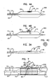
- Catheter assembly 200 includes many of the same or similar features as described above with reference to catheter assembly 100 except that the EAP valve 30 is replaced with a membrane 40 without EAP properties.
- the membrane 40 is positioned between the first and second balloons 14, 16.
- the membrane 40 is integrated into a side wall of the first balloon 14 that is at least partially enclosed by the balloon 16.
- the membrane 40 is configured to be modified or otherwise operated at some point during inflation of first balloon 14 to provide a fluid flow path between the interior of the first balloon 14 and an interior of the second balloon 16.
- Figure 3A illustrates that catheter assembly 200 with the first and second balloons 14, 16 in a deflated state.
- Figure 3B illustrates the first balloon 14 inflated via the inflation lumen 20.
- Figure 3C illustrates the membrane 40 in a modified state in which an opening 42 is defined. Fluid flows from the first balloon 14 through the opening 42 into the second balloon 16 to inflate the second balloon 16 into the radially extended position.
- the membrane 40 can be configured to generate the opening 42 in any of a plurality of different ways.
- the membrane 40 can be configured to rupture automatically when a certain pressure threshold is reached within the first balloon 14.
- the membrane 40 can include stress lines that tear to provide at least one slit opening upon reaching a threshold pressure condition in the first balloon 14.
- a mechanical structure can be coupled to the membrane 40 to puncture or otherwise initiate generation of the opening 42 at a desired point in time.
- a pull member is connected to the membrane 40 at a distal end of the pull member, and a proximal end of the pull member is accessible by an operator of the catheter assembly 200. Pulling of the proximal end of the pull member creates the opening 42.
- An example pull member includes a cable or wire structure.
- FIG. 3 Another example catheter assembly 300 is described with reference to Figures 4A-B .
- the catheter assembly 300 has many of the same features as described above with reference to catheter assembly 100 except that the EAP valve 30 is replaced with a mechanical expansion member 50.
- the mechanical expansion member 50 upon activation, is configured to extend the second balloon 16 from a first non-deployed position shown in Figure 4A to a deployed, radially extended position shown in Figure 4B .
- Mechanical expansion member 50 is capable of moving the second balloon 16 into the radially extended position without the use of an inflation fluid.
- the mechanical expansion member 52 is positioned between the first and second balloons 14, 16.
- a first side 51 of the expansion member 50 engages an outer sidewall of the first balloon 14.
- a second side 53 of the expansion member 50 engages the second balloon 16.
- the expansion member 50 may be more effective at moving the second balloon 16 into the radially extended position shown in Figure 4B when the first balloon 14 has already been at least inflated.
- An activator 52 can be coupled to the mechanical expansion member 50 to initiate activation of the expansion member 50 from the non-deployed state shown in Figure 4A to the deployed state shown in Figure 4B .
- the activator 50 similar to the activation wire 34 shown in Figures 2A-B , extends within the first balloon 14 and catheter shaft 12 to a proximal location accessible by an operator of the catheter assembly 300.
- the activator 52 can have different functions depending on the type of mechanical expansion member 50 being used.
- the activator 52 can be a pull wire that mechanically releases the mechanical expansion member 50 so that it can move from the non-deployed to deployed state.
- the activator 52 can be an electrical coupling that provides an electrical stimulus to the mechanical expansion member 50 that initiates the deployed state.
- the mechanical expansion member 50 can comprise a thermal shaped memory material such as Nitinol (Nickel Titanium Naval Ordnance Laboratory) that provides bimodal actuation initiated by an applied voltage or current.
- Thermal shape memory material provides for a change in shape of the mechanical expansion member 50 by heating the material above a transition temperature.
- the transition temperature for thermal shaped memory material Flexinol® made by Dynalloy of Costa Mesa, California is about 70°C.
- the transition temperature of other thermal shaped memory materials can be higher or lower depending on the specific material composition.
- thermal shaped memory material When a thermal shaped memory material is cooled, it can be stretched or otherwise formed into a new shape different from the original shape.
- the original shape By including thermal shaped memory material in the construction of the mechanical expansion member 50, the original shape can be the extended, deployed configuration shown in Figure 4B , and the shape maintained when below the transition temperature is the non-deployed state shown in Figure 4A .
- Some types of thermal shaped memory material can be heated to its transition temperature using the body heat of the patient into which the catheter assembly 300 is introduced. Using the patient's body as the heat source, it is possible to estimate a range of time required to reach the transition temperature beginning with introduction of the catheter assembly 300 into the patient.
- the thermal shaped memory material can also be heated using an electric current or other heat source besides the patient's body such as, for example, heat from the inflation fluid used to inflate the first balloon 14.
- Figure 4C illustrates a top view of the mechanical expansion member 50 in a coiled configuration.
- Other shapes and structures for mechanical expansion member 50 can be used such as, for example, a crown-type structure.
- the mechanical expansion member 50 can be bounded or otherwise secured to either or both of the first and second balloons 14, 16. Alternatively, the mechanical expansion member 50 can be loosely held in the space defined between the first and second balloons 14, 16.
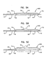
- the catheter assembly 400 has many of the same features as described above with reference to catheter assemblies 100, 200, 300 except that the second balloon 16 is positioned on a distal end portion 70 of the secondary inflation lumen 22.
- the distal end portion 70 of the secondary inflation lumen 22 has a distal end 72 that is secured to the guidewire housing that defines guidewire lumen 18 at a location distal of the main balloon distal end 15.
- the secondary inflation lumen 22 exits the catheter shaft 12 at a point 74 along the distal end portion 70.
- a proximal end portion of the secondary inflation lumen is in fluid communication with a manifold, such as manifold 24 shown in Figures 1A-D .
- the secondary inflation lumen 22 extends along an exterior of the catheter shaft 12 from the proximal end portion of the shaft 12 to the first balloon 14.
- the secondary inflation lumen 22 can be secured to the outer surface of the catheter shaft 12 or the first balloon 14 using, for example, heat bonding or adhesives.
- the distal end 72 of the distal end portion 70 of the secondary inflation lumen 22 can be truncated and the distal end portion 70 secured to an exterior of the first balloon 14 at a location proximal or distal of the second balloon 16.
- Inflation of the second balloon 16 can be controlled using any of the structures and configuration described above with reference to Figures 1-4C .
- a valve structure such as an EAP valve can be positioned within the secondary inflation lumen, or a mechanical expansion member 50 can be positioned within the second balloon 16.
- the second balloon can be positioned on a separate catheter branch that is positioned within a branch vessel of a vessel bifurcation and inflated using the valving and inflation techniques discussed herein.
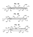
- the catheter assembly 500 includes many of the same or similar features as described above related to Figures 5A-C .
- the catheter assembly 500 includes a secondary inflation lumen 22 that provides inflation fluid to the secondary balloon 16.
- the secondary inflation lumen 22 intersects the inflation lumen 20 proximal of the main balloon 14 at a proximal end portion 74 of the secondary inflation lumen 22.
- a valve arrangement 75 is positioned along the secondary inflation lumen at a location between the inflation lumen 20 and the secondary balloon 16.
- the valve arrangement 75 is shown schematically in Figures 6A-C at a location where the secondary inflation lumen 22 intersects the distal end portion of the catheter shaft 12.
- the valve arrangement 75 can be positioned at other locations such as, for example, at or near a distal end portion 72 of the secondary inflation lumen 22.
- the valve arrangement 75 can include any of the valve member configurations described above, for example, those configurations described with reference to Figures 1A-4C .
- the valve arrangement 75 can include an EAP material, a pull member, or a pressure sensitive membrane.
- the catheter assembly 200 shown with reference to Figures 3A-C is shown in Figure 7 in use with a stent 70 to treat a vessel bifurcation 60.
- the vessel bifurcation includes a main vessel 62 and a branch vessel 64 branching off of the main vessel 62.
- An ostium 63 of the branch vessel 64 is defined as the opening into the branch vessel 64 along a sidewall of the main vessel 62.
- the stent 70 is an elongate tubular structure having opposing open ends.
- the stent 70 includes a plurality of structures along its length that permit expansion of the stent from an unexpanded state (not shown) to the expanded state shown in Figure 7 .
- the plurality of structures of the stent define a series of cell openings.
- the stent 90 includes a separate lateral branch opening 92 defined in a sidewall of the stent between the opposing open ends of the stent.
- the lateral branch opening 92 is usually larger than the cell opening, but can be the same or a smaller size than the cell openings.
- the lateral branch opening 92 is defined by a band of continuous material that defines a perimeter of the lateral branch opening 92.
- This continuous band of material preferably includes discontinuities over its length so that the area of the lateral branch opening 92 expands together with the expansion of the stent 90.
- the continuous band includes protrusions that project inwardly from a peripheral edge of the lateral branch opening 92. These protrusions (also referenced as expandable structure 94) are initially positioned within a cylindrical envelope of the tubular body of the stent 90.
- the expandable structure 94 can expand at least partially radially outward from a main body of the stent 90 outside of the cylindrical envelope of the main body of the stent 90 upon inflation of the second balloon 16.
- the stent 90 is positioned on the first balloon 14 between proximal and distal ends of the balloon 14.
- the lateral branch opening 92 is aligned with the second balloon 16 such that moving the second balloon 16 into a radially extended position will cause the second balloon 16 to at least partially extend through the lateral branch opening 92 toward the ostium 63 of the branch vessel 64.
- Expanding the expandable structure 94 can extend that expandable structure 94 through the ostium of the branch vessel 64 to treat, for example, portions of the main and branch vessels 62, 64.
- Expanding the expandable structure 74 can provide a larger path through the lateral branch opening 92 of the stent 90 into the branch 64 for passage of additional treatment or alignment devices used after deflation of the first and second balloons 14, 16.
- the main body of the stent 90 When treating the vessel 60, it is sometimes preferable to first fix the main body of the stent 90 within the main vessel 62 prior to expanding the expandable structures in the radially outward facing direction into the branch vessel 64. In order to ensure this sequence of expansion of features of the stent 90, a delay is provided for inflating or otherwise radial extending the balloon 16 until after the first balloon 14 has been fully inflated to expand the main body of the stent 90 into engagement with the main vessel 62.
- the EAP valve 30 of Figures 2A-B , the openable membrane 40 shown in Figures 3A-C , or the mechanical expansion member 50 shown in Figures 4A-C described above can provide the desired sequence of first inflating the first balloon 14 followed by radially extending the second balloon 16.
- the first balloon 14 is inflated to expand the main body of stent 90 followed by modification of the membrane 40 to create the opening 42 thereby inflating the second balloon 16 to radially extend the expandable structure 94.
- a side catheter branch that defines a branch guidewire lumen for receiving a branch guidewire can extend parallel with the catheter shaft 12 to the vessel bifurcation 60.
- the side catheter branch extends through the proximal open end of the stent 90, out of the lateral branch opening 92, and into the branch vessel 64.
- the guidewire 17 is located in the main vessel 62 distally of the ostium 63, and the branch guidewire is positioned within the branch vessel 64.
- the stent 90 is pre-positioned around the first and second balloons 14, 16 with the second balloon aligned with the lateral branch opening 92 of the stent 90.
- the side catheter branch is also pre-positioned extending through the lateral branch opening 92.
- the catheter assembly 10 with stent 90 and the side catheter branch are then advanced over the guidewire 17 and the branch guidewire to the vessel bifurcation 60.
- a distal end of the side catheter branch automatically advances into the branch vessel 64 over the branch guidewire as the catheter assembly 10 is positioned across the vessel bifurcation.
- the side catheter branch can help rotationally align the lateral branch opening 92 with the ostium 63 because it is extending through both the lateral branch opening 92 and the ostium 63.
- Another catheter alignment feature that can be used with catheter assemblies 100, 200, 300 is a marker system. Positioning radiopaque markers along the side catheter branch (discussed above), the catheter shaft 12, and the balloon 14 can help the physician visualize under fluoroscopy when the side catheter branch has advanced into the branch vessel 64.
- markers and marker materials are described in U.S. Pat. No. 6,692,483 to Vardi, et al. , and co-pending U.S. Provisional Patent Application Serial No. 60/776,149, filed on February 22, 2006 , and titled MARKER ARRANGEMENT FOR BIFURCATION CATHETER.
- at least two axially spaced apart markers can be positioned on opposing ends of the balloon 14 and at least two markers positioned along the side catheter branch.
- Relative positioning of the four markers can provide information about relative radial position of the side catheter branch and catheter shaft 12, which can be used in axial and radial alignment of the balloon 16 and stent lateral branch opening 92 relative to the ostium 63 of branch vessel 64.
- the stent 90 can be used in a similar way for treatment of a vessel bifurcation using the other catheter assemblies and principles disclosed herein.
- the catheter shaft includes a distal end portion and a proximal end portion.
- the main balloon is positioned at the distal end portion of the catheter shaft.
- the main balloon is operable between an unexpanded configuration and an expanded configuration.
- the secondary balloon is also positioned at the distal end portion of the catheter shaft.
- the secondary balloon is operable between an unexpanded configuration in which the second balloon is positioned adjacent to the main balloon and an expanded configuration in which the second balloon extends radially outward relative to the main balloon.
- the actuator arrangement is configured to operate the secondary balloon between the unexpanded configuration to the expanded configuration independently of operation of the main balloon between the unexpanded and expanded configurations.
- the catheter assembly can further include a stent having a lateral branch opening. At least a portion of the secondary balloon extends through the lateral branch opening when the second balloon is in the expanded configuration.
- the actuator arrangement can have various configurations such as a membrane that ruptures when a threshold pressure condition is exceeded, a membrane that ruptures in response to an applied potential, a pull member configured to generate an opening in the membrane, or a mechanical actuator positioned within the secondary balloon that actuates the secondary balloon between the unexpanded and expanded configurations.
- the vessel bifurcation includes a main vessel and a branch vessel extending from the main vessel.
- the catheter assembly includes a catheter shaft having proximal and distal end portions, a first balloon positioned at the distal end portion of the catheter shaft, a second balloon positioned at the distal end portion of the catheter shaft, and an actuator arrangement.
- the method steps include positioning the catheter assembly within the main vessel with the second balloon oriented facing an ostium of the branch vessel, inflating the first balloon, and after the step of inflating the first balloon, operating the actuator arrangement to expand the second balloon in a radially outward direction relative to the first balloon.
- a further aspect of the present disclosure relates to another catheter assembly.
- the catheter assembly includes a catheter shaft having a proximal end portion and a distal end portion, a first balloon member positioned at the distal end portion of the catheter shaft, a second balloon member positioned at the distal end portion of the catheter shaft and configured to expand radially outward relative to the first balloon member, first and second inflation housings defining first and second inflation lumens, and a valve member.
- the first inflation lumen extends from the proximal end portion to the distal end portion of the catheter shaft.
- the first inflation lumen is coupled in fluid communication with the first balloon.
- the second inflation lumen extends from the proximal end portion to the distal end portion of the catheter shaft.
- the second inflation lumen is coupled in fluid communication with the second balloon.
- the valve member is adjustable between a first position connecting a fluid source in fluid communication with the first inflation lumen while preventing fluid communication between the fluid source and the second inflation lumen, a second position connecting the fluid source in fluid communication with the second inflation lumen while preventing fluid communication between the fluid source and the first inflation lumen, and a third position wherein the fluid source is not in fluid communication with the first and second inflation lumens.
- a further aspect of the present disclosure relates to a method of operating a balloon catheter.
- the balloon catheter includes a catheter shaft having proximal and distal end portions, first and second balloons positioned at the distal end portion of the catheter shaft, and a manifold positioned at the proximal end portion of the catheter shaft.
- the second balloon is configured to extend radially outward relative to the first balloon.
- the method includes the step of operating the manifold to connect the first balloon in fluid communication with an inflation source while preventing fluid communication between the fluid source and the second balloon.
- the method further includes, after operating the manifold to connect the first balloon in fluid communication with the inflation source, operating the manifold to connect the second balloon in fluid communication with the inflation source while preventing fluid communication between the fluid source and the first balloon.
Landscapes
- Health & Medical Sciences (AREA)
- Engineering & Computer Science (AREA)
- Biomedical Technology (AREA)
- Heart & Thoracic Surgery (AREA)
- Life Sciences & Earth Sciences (AREA)
- Animal Behavior & Ethology (AREA)
- Veterinary Medicine (AREA)
- Public Health (AREA)
- General Health & Medical Sciences (AREA)
- Transplantation (AREA)
- Vascular Medicine (AREA)
- Oral & Maxillofacial Surgery (AREA)
- Cardiology (AREA)
- Child & Adolescent Psychology (AREA)
- Biophysics (AREA)
- Pulmonology (AREA)
- Anesthesiology (AREA)
- Hematology (AREA)
- Media Introduction/Drainage Providing Device (AREA)
- Materials For Medical Uses (AREA)
Applications Claiming Priority (2)
| Application Number | Priority Date | Filing Date | Title |
|---|---|---|---|
| US11/832,394 US8486134B2 (en) | 2007-08-01 | 2007-08-01 | Bifurcation treatment system and methods |
| PCT/US2008/071887 WO2009029385A1 (en) | 2007-08-01 | 2008-08-01 | Bifurcation treatment system and methods |
Publications (2)
| Publication Number | Publication Date |
|---|---|
| EP2178593A1 EP2178593A1 (en) | 2010-04-28 |
| EP2178593B1 true EP2178593B1 (en) | 2012-10-24 |
Family
ID=40193940
Family Applications (1)
| Application Number | Title | Priority Date | Filing Date |
|---|---|---|---|
| EP08828714A Not-in-force EP2178593B1 (en) | 2007-08-01 | 2008-08-01 | Bifurcation treatment system |
Country Status (4)
| Country | Link |
|---|---|
| US (1) | US8486134B2 (enExample) |
| EP (1) | EP2178593B1 (enExample) |
| JP (1) | JP2010535095A (enExample) |
| WO (1) | WO2009029385A1 (enExample) |
Families Citing this family (8)
| Publication number | Priority date | Publication date | Assignee | Title |
|---|---|---|---|---|
| JP5504173B2 (ja) * | 2007-12-31 | 2014-05-28 | ボストン サイエンティフィック サイムド,インコーポレイテッド | 血管分岐部の処置のためのカテーテルアセンブリ |
| US20090287148A1 (en) | 2008-05-15 | 2009-11-19 | Martin Daryl L | Joined Inflation Portions for Bifurcation Catheter |
| US8377108B2 (en) | 2008-06-02 | 2013-02-19 | Boston Scientific Scimed, Inc. | Staggered two balloon bifurcation catheter assembly and methods |
| US8398697B2 (en) * | 2008-06-13 | 2013-03-19 | Boston Scientific Scimed, Inc. | Bifurcation catheter assembly with distally mounted side balloon and methods |
| US20090326643A1 (en) * | 2008-06-27 | 2009-12-31 | Boston Scientific Scimed, Inc. | Balloon folding apparatus and method |
| WO2020072837A1 (en) * | 2018-10-03 | 2020-04-09 | Ostial Corporation | Inflation devices and systems for balloon catheters and methods for use |
| US11786707B2 (en) | 2019-04-08 | 2023-10-17 | Astikay Medical LLC | Inflatable balloon over catheter with bypass passageway |
| US11666744B2 (en) * | 2020-05-29 | 2023-06-06 | Basis Medical, Llc | Multi-lumen manifold and method of operating a multi-lumen manifold |
Citations (1)
| Publication number | Priority date | Publication date | Assignee | Title |
|---|---|---|---|---|
| WO2005082440A1 (en) * | 2004-02-26 | 2005-09-09 | V-Kardia Pty Ltd | Isolating cardiac circulation |
Family Cites Families (309)
| Publication number | Priority date | Publication date | Assignee | Title |
|---|---|---|---|---|
| US3872893A (en) | 1972-05-01 | 1975-03-25 | Fred T Roberts & Company | Self-reinforced plastic hose and method for molding same |
| IN144765B (enExample) | 1975-02-12 | 1978-07-01 | Rasmussen O B | |
| US4140126A (en) | 1977-02-18 | 1979-02-20 | Choudhury M Hasan | Method for performing aneurysm repair |
| US4309994A (en) | 1980-02-25 | 1982-01-12 | Grunwald Ronald P | Cardiovascular cannula |
| US4413989A (en) | 1980-09-08 | 1983-11-08 | Angiomedics Corporation | Expandable occlusion apparatus |
| US4410476A (en) | 1980-10-20 | 1983-10-18 | The United States Of America As Represented By The Secretary Of The Navy | Method for making radially compliant line array hose |
| JPS6010740B2 (ja) | 1981-05-07 | 1985-03-19 | 宏司 井上 | 一側肺換気用気管内チユ−ブ |
| US4946464A (en) | 1981-07-22 | 1990-08-07 | Pevsner Paul H | Method of manufacturing miniature balloon catheter and product thereof |
| US5085654A (en) | 1982-11-15 | 1992-02-04 | The Procter & Gamble Company | Disposable garment with breathable leg cuffs |
| US4503569A (en) | 1983-03-03 | 1985-03-12 | Dotter Charles T | Transluminally placed expandable graft prosthesis |
| US4939240A (en) | 1983-03-04 | 1990-07-03 | Health Research, Inc. | Monoclonal antibodies to human breast carcinoma cells and their use in diagnosis and therapy |
| CA1194662A (en) | 1983-07-12 | 1985-10-08 | Lupke, Manfred A. A. | Producing double-walled helically wound thermoplastic pipe |
| US4552554A (en) | 1984-06-25 | 1985-11-12 | Medi-Tech Incorporated | Introducing catheter |
| EP0203124B1 (en) | 1984-11-15 | 1991-06-05 | NAZARI, Stefano | Device for selective bronchial intubation and separate lung ventilation |
| US4733665C2 (en) | 1985-11-07 | 2002-01-29 | Expandable Grafts Partnership | Expandable intraluminal graft and method and apparatus for implanting an expandable intraluminal graft |
| US5102417A (en) | 1985-11-07 | 1992-04-07 | Expandable Grafts Partnership | Expandable intraluminal graft, and method and apparatus for implanting an expandable intraluminal graft |
| US4681570A (en) | 1985-12-26 | 1987-07-21 | Dalton Michael J | Peritoneal catheter |
| US5000185A (en) | 1986-02-28 | 1991-03-19 | Cardiovascular Imaging Systems, Inc. | Method for intravascular two-dimensional ultrasonography and recanalization |
| US5350395A (en) | 1986-04-15 | 1994-09-27 | Yock Paul G | Angioplasty apparatus facilitating rapid exchanges |
| US4964850A (en) | 1986-05-07 | 1990-10-23 | Vincent Bouton | Method for treating trans-nasal sinus afflictions using a double t-shaped trans-nasal aerator |
| US4759748A (en) | 1986-06-30 | 1988-07-26 | Raychem Corporation | Guiding catheter |
| US4731055A (en) | 1986-08-25 | 1988-03-15 | Becton, Dickinson And Company | Blood flow conduit |
| JPH0763489B2 (ja) | 1986-10-31 | 1995-07-12 | 宇部興産株式会社 | 医療用チユ−ブ |
| US4762128A (en) | 1986-12-09 | 1988-08-09 | Advanced Surgical Intervention, Inc. | Method and apparatus for treating hypertrophy of the prostate gland |
| US4748982A (en) | 1987-01-06 | 1988-06-07 | Advanced Cardiovascular Systems, Inc. | Reinforced balloon dilatation catheter with slitted exchange sleeve and method |
| AU610119B2 (en) | 1987-01-13 | 1991-05-16 | Terumo Kabushiki Kaisha | Balloon catheter and production thereof |
| US4878495A (en) | 1987-05-15 | 1989-11-07 | Joseph Grayzel | Valvuloplasty device with satellite expansion means |
| US4872874A (en) | 1987-05-29 | 1989-10-10 | Taheri Syde A | Method and apparatus for transarterial aortic graft insertion and implantation |
| US4769029A (en) | 1987-06-19 | 1988-09-06 | Patel Jayendrakumar I | Prosthetic graft for arterial system repair |
| FR2632864B2 (fr) | 1987-12-31 | 1990-10-19 | Biomat Sarl | Systeme filtrant elastique anti-embolique pour veine cave et ensemble de moyens pour sa mise en place |
| US4900314A (en) | 1988-02-01 | 1990-02-13 | Fbk International Corporation | Collapse-resistant tubing for medical use |
| FR2627982B1 (fr) | 1988-03-02 | 1995-01-27 | Artemis | Endoprothese tubulaire pour conduits anatomiques, et instrument et procede pour sa mise en place |
| US4896670A (en) | 1988-04-19 | 1990-01-30 | C. R. Bard, Inc. | Kissing balloon catheter |
| US4909258A (en) | 1988-08-08 | 1990-03-20 | The Beth Israel Hospital Association | Internal mammary artery (IMA) catheter |
| US5226913A (en) | 1988-09-01 | 1993-07-13 | Corvita Corporation | Method of making a radially expandable prosthesis |
| US4906244A (en) | 1988-10-04 | 1990-03-06 | Cordis Corporation | Balloons for medical devices and fabrication thereof |
| CA1322628C (en) | 1988-10-04 | 1993-10-05 | Richard A. Schatz | Expandable intraluminal graft |
| US4983167A (en) | 1988-11-23 | 1991-01-08 | Harvinder Sahota | Balloon catheters |
| US4994071A (en) | 1989-05-22 | 1991-02-19 | Cordis Corporation | Bifurcating stent apparatus and method |
| US5324457A (en) | 1989-10-02 | 1994-06-28 | Board Of Regents, The University Of Tx System | Devices and methods for generating electrogenerated chemiluminescence |
| IE73670B1 (en) | 1989-10-02 | 1997-07-02 | Medtronic Inc | Articulated stent |
| US5217440A (en) | 1989-10-06 | 1993-06-08 | C. R. Bard, Inc. | Multilaminate coiled film catheter construction |
| US5531788A (en) | 1989-10-09 | 1996-07-02 | Foundation Pour L'avenir Pour La Recherche Medicale Appliquee | Anti-Pulmonary embolism filter |
| DE3935256C1 (enExample) | 1989-10-23 | 1991-01-03 | Bauerfeind, Peter, Dr., 8264 Waldkraiburg, De | |
| US5147385A (en) | 1989-11-01 | 1992-09-15 | Schneider (Europe) A.G. | Stent and catheter for the introduction of the stent |
| US5176617A (en) | 1989-12-11 | 1993-01-05 | Medical Innovative Technologies R & D Limited Partnership | Use of a stent with the capability to inhibit malignant growth in a vessel such as a biliary duct |
| US5117831A (en) | 1990-03-28 | 1992-06-02 | Cardiovascular Imaging Systems, Inc. | Vascular catheter having tandem imaging and dilatation components |
| US5061240A (en) | 1990-04-02 | 1991-10-29 | George Cherian | Balloon tip catheter for venous valve ablation |
| US5059177A (en) | 1990-04-19 | 1991-10-22 | Cordis Corporation | Triple lumen balloon catheter |
| US5122125A (en) | 1990-04-25 | 1992-06-16 | Ashridge A.G. | Catheter for angioplasty with soft centering tip |
| US5054501A (en) | 1990-05-16 | 1991-10-08 | Brigham & Women's Hospital | Steerable guide wire for cannulation of tubular or vascular organs |
| US5147317A (en) | 1990-06-04 | 1992-09-15 | C.R. Bard, Inc. | Low friction varied radiopacity guidewire |
| US5578071A (en) | 1990-06-11 | 1996-11-26 | Parodi; Juan C. | Aortic graft |
| US5159920A (en) | 1990-06-18 | 1992-11-03 | Mentor Corporation | Scope and stent system |
| US5102403A (en) | 1990-06-18 | 1992-04-07 | Eckhard Alt | Therapeutic medical instrument for insertion into body |
| US5064435A (en) | 1990-06-28 | 1991-11-12 | Schneider (Usa) Inc. | Self-expanding prosthesis having stable axial length |
| US5395332A (en) | 1990-08-28 | 1995-03-07 | Scimed Life Systems, Inc. | Intravascualr catheter with distal tip guide wire lumen |
| US5217482A (en) | 1990-08-28 | 1993-06-08 | Scimed Life Systems, Inc. | Balloon catheter with distal guide wire lumen |
| EP0479730B1 (de) | 1990-10-04 | 1995-04-19 | Schneider (Europe) Ag | Ballondilationskatheter |
| CA2060067A1 (en) | 1991-01-28 | 1992-07-29 | Lilip Lau | Stent delivery system |
| US5135536A (en) | 1991-02-05 | 1992-08-04 | Cordis Corporation | Endovascular stent and method |
| WO1992016163A1 (fr) | 1991-03-14 | 1992-10-01 | Ethnor | Filtre anti-embolie pulmonaire perfectionne et kit de presentation et mise en place correspondante |
| CA2202800A1 (en) | 1991-04-11 | 1992-10-12 | Alec A. Piplani | Endovascular graft having bifurcation and apparatus and method for deploying the same |
| US5628783A (en) | 1991-04-11 | 1997-05-13 | Endovascular Technologies, Inc. | Bifurcated multicapsule intraluminal grafting system and method |
| US5244619A (en) | 1991-05-03 | 1993-09-14 | Burnham Warren R | Method of making catheter with irregular inner and/or outer surfaces to reduce travelling friction |
| US5304220A (en) | 1991-07-03 | 1994-04-19 | Maginot Thomas J | Method and apparatus for implanting a graft prosthesis in the body of a patient |
| US5211683A (en) | 1991-07-03 | 1993-05-18 | Maginot Thomas J | Method of implanting a graft prosthesis in the body of a patient |
| FR2678508B1 (fr) | 1991-07-04 | 1998-01-30 | Celsa Lg | Dispositif pour le renfort de vaisseaux du corps humain. |
| DE69228184T2 (de) | 1991-07-04 | 1999-09-16 | Earl Owen | Rohrförmiges, chirurgisches implantat |
| US5234457A (en) | 1991-10-09 | 1993-08-10 | Boston Scientific Corporation | Impregnated stent |
| US5693084A (en) | 1991-10-25 | 1997-12-02 | Cook Incorporated | Expandable transluminal graft prosthesis for repair of aneurysm |
| US5387235A (en) | 1991-10-25 | 1995-02-07 | Cook Incorporated | Expandable transluminal graft prosthesis for repair of aneurysm |
| AU669338B2 (en) | 1991-10-25 | 1996-06-06 | Cook Incorporated | Expandable transluminal graft prosthesis for repair of aneurysm and method for implanting |
| CA2079417C (en) | 1991-10-28 | 2003-01-07 | Lilip Lau | Expandable stents and method of making same |
| FR2683449A1 (fr) | 1991-11-08 | 1993-05-14 | Cardon Alain | Endoprothese pour implantation transluminale. |
| US5192297A (en) | 1991-12-31 | 1993-03-09 | Medtronic, Inc. | Apparatus and method for placement and implantation of a stent |
| US5316023A (en) | 1992-01-08 | 1994-05-31 | Expandable Grafts Partnership | Method for bilateral intra-aortic bypass |
| US5571087A (en) | 1992-02-10 | 1996-11-05 | Scimed Life Systems, Inc. | Intravascular catheter with distal tip guide wire lumen |
| US5505702A (en) | 1992-04-09 | 1996-04-09 | Scimed Life Systems, Inc. | Balloon catheter for dilatation and perfusion |
| US5263932A (en) | 1992-04-09 | 1993-11-23 | Jang G David | Bailout catheter for fixed wire angioplasty |
| US5342387A (en) | 1992-06-18 | 1994-08-30 | American Biomed, Inc. | Artificial support for a blood vessel |
| DE4222380A1 (de) | 1992-07-08 | 1994-01-13 | Ernst Peter Prof Dr M Strecker | In den Körper eines Patienten perkutan implantierbare Endoprothese |
| US5342297A (en) | 1992-07-10 | 1994-08-30 | Jang G David | Bailout receptacle for angioplasty catheter |
| US5257974A (en) | 1992-08-19 | 1993-11-02 | Scimed Life Systems, Inc. | Performance enhancement adaptor for intravascular balloon catheter |
| US5562725A (en) | 1992-09-14 | 1996-10-08 | Meadox Medicals Inc. | Radially self-expanding implantable intraluminal device |
| US5449382A (en) | 1992-11-04 | 1995-09-12 | Dayton; Michael P. | Minimally invasive bioactivated endoprosthesis for vessel repair |
| US5320605A (en) | 1993-01-22 | 1994-06-14 | Harvinder Sahota | Multi-wire multi-balloon catheter |
| WO1994016633A1 (en) | 1993-01-29 | 1994-08-04 | United States Of America, As Represented By The Secretary, Department Of Health And Human Services | Multifinger topocatheter tip for multilumen catheter for angioplasty and manipulation |
| US5383856A (en) | 1993-03-19 | 1995-01-24 | Bersin; Robert M. | Helical spiral balloon catheter |
| US5464650A (en) | 1993-04-26 | 1995-11-07 | Medtronic, Inc. | Intravascular stent and method |
| US5549553A (en) | 1993-04-29 | 1996-08-27 | Scimed Life Systems, Inc. | Dilation ballon for a single operator exchange intravascular catheter or similar device |
| US5282472A (en) | 1993-05-11 | 1994-02-01 | Companion John A | System and process for the detection, evaluation and treatment of prostate and urinary problems |
| US5458608A (en) | 1993-06-03 | 1995-10-17 | Surgin Surgical Instrumentation Inc. | Laparoscopic instruments and methods |
| FR2706764B1 (enExample) | 1993-06-24 | 1995-08-04 | Synthelabo | |
| US5425765A (en) | 1993-06-25 | 1995-06-20 | Tiefenbrun; Jonathan | Surgical bypass method |
| IL106738A (en) | 1993-08-19 | 1998-02-08 | Mind E M S G Ltd | Device for external correction of deficient valves in venous junctions |
| US5913897A (en) | 1993-09-16 | 1999-06-22 | Cordis Corporation | Endoprosthesis having multiple bridging junctions and procedure |
| US5342295A (en) | 1993-09-24 | 1994-08-30 | Cardiac Pathways Corporation | Catheter assembly, catheter and multi-port introducer for use therewith |
| US5417208A (en) | 1993-10-12 | 1995-05-23 | Arrow International Investment Corp. | Electrode-carrying catheter and method of making same |
| US5723004A (en) | 1993-10-21 | 1998-03-03 | Corvita Corporation | Expandable supportive endoluminal grafts |
| US5639278A (en) | 1993-10-21 | 1997-06-17 | Corvita Corporation | Expandable supportive bifurcated endoluminal grafts |
| US5632772A (en) | 1993-10-21 | 1997-05-27 | Corvita Corporation | Expandable supportive branched endoluminal grafts |
| US5404887A (en) | 1993-11-04 | 1995-04-11 | Scimed Life Systems, Inc. | Guide wire having an unsmooth exterior surface |
| WO1995013033A1 (en) | 1993-11-08 | 1995-05-18 | Lazarus Harrison M | Intraluminal vascular graft and method |
| US5409458A (en) | 1993-11-10 | 1995-04-25 | Medtronic, Inc. | Grooved balloon for dilatation catheter |
| US5443497A (en) | 1993-11-22 | 1995-08-22 | The Johns Hopkins University | Percutaneous prosthetic by-pass graft and method of use |
| US5607444A (en) | 1993-12-02 | 1997-03-04 | Advanced Cardiovascular Systems, Inc. | Ostial stent for bifurcations |
| DE9319267U1 (de) | 1993-12-15 | 1994-02-24 | Günther, Rudolf W., Prof. Dr., 52074 Aachen | Aortenendoprothese |
| US5545132A (en) | 1993-12-21 | 1996-08-13 | C. R. Bard, Inc. | Helically grooved balloon for dilatation catheter and method of using |
| JP2703510B2 (ja) | 1993-12-28 | 1998-01-26 | アドヴァンスド カーディオヴァスキュラー システムズ インコーポレーテッド | 拡大可能なステント及びその製造方法 |
| US5445624A (en) | 1994-01-21 | 1995-08-29 | Exonix Research Corporation | Catheter with progressively compliant tip |
| US5609627A (en) | 1994-02-09 | 1997-03-11 | Boston Scientific Technology, Inc. | Method for delivering a bifurcated endoluminal prosthesis |
| US6039749A (en) | 1994-02-10 | 2000-03-21 | Endovascular Systems, Inc. | Method and apparatus for deploying non-circular stents and graftstent complexes |
| US5507769A (en) | 1994-10-18 | 1996-04-16 | Stentco, Inc. | Method and apparatus for forming an endoluminal bifurcated graft |
| US5843116A (en) * | 1996-05-02 | 1998-12-01 | Cardiovascular Dynamics, Inc. | Focalized intraluminal balloons |
| US6120523A (en) | 1994-02-24 | 2000-09-19 | Radiance Medical Systems, Inc. | Focalized intraluminal balloons |
| US5733303A (en) | 1994-03-17 | 1998-03-31 | Medinol Ltd. | Flexible expandable stent |
| US5843120A (en) | 1994-03-17 | 1998-12-01 | Medinol Ltd. | Flexible-expandable stent |
| US5449373A (en) | 1994-03-17 | 1995-09-12 | Medinol Ltd. | Articulated stent |
| US5489271A (en) | 1994-03-29 | 1996-02-06 | Boston Scientific Corporation | Convertible catheter |
| US5549554A (en) | 1994-04-01 | 1996-08-27 | Advanced Cardiovascular Systems, Inc. | Catheters having separable reusable components |
| US5613949A (en) | 1994-04-01 | 1997-03-25 | Advanced Cardiovascular Systems, Inc. | Double balloon catheter assembly |
| US5824044A (en) | 1994-05-12 | 1998-10-20 | Endovascular Technologies, Inc. | Bifurcated multicapsule intraluminal grafting system |
| US5456694A (en) | 1994-05-13 | 1995-10-10 | Stentco, Inc. | Device for delivering and deploying intraluminal devices |
| US5824041A (en) | 1994-06-08 | 1998-10-20 | Medtronic, Inc. | Apparatus and methods for placement and repositioning of intraluminal prostheses |
| US5683451A (en) | 1994-06-08 | 1997-11-04 | Cardiovascular Concepts, Inc. | Apparatus and methods for deployment release of intraluminal prostheses |
| US5582616A (en) | 1994-08-05 | 1996-12-10 | Origin Medsystems, Inc. | Surgical helical fastener with applicator |
| US5575817A (en) | 1994-08-19 | 1996-11-19 | Martin; Eric C. | Aorto femoral bifurcation graft and method of implantation |
| US5609605A (en) | 1994-08-25 | 1997-03-11 | Ethicon, Inc. | Combination arterial stent |
| US5653743A (en) | 1994-09-09 | 1997-08-05 | Martin; Eric C. | Hypogastric artery bifurcation graft and method of implantation |
| US6102929A (en) * | 1994-09-15 | 2000-08-15 | Mentor Urology, Inc. | Prostatic tissue expander |
| US5599305A (en) | 1994-10-24 | 1997-02-04 | Cardiovascular Concepts, Inc. | Large-diameter introducer sheath having hemostasis valve and removable steering mechanism |
| JP2911763B2 (ja) | 1994-10-27 | 1999-06-23 | 三桜子 布川 | 人工血管 |
| CA2134997C (en) | 1994-11-03 | 2009-06-02 | Ian M. Penn | Stent |
| CA2175720C (en) | 1996-05-03 | 2011-11-29 | Ian M. Penn | Bifurcated stent and method for the manufacture and delivery of same |
| AU3783195A (en) | 1994-11-15 | 1996-05-23 | Advanced Cardiovascular Systems Inc. | Intraluminal stent for attaching a graft |
| US5613980A (en) | 1994-12-22 | 1997-03-25 | Chauhan; Tusharsindhu C. | Bifurcated catheter system and method |
| US5522801A (en) | 1995-01-18 | 1996-06-04 | Wang; Abe | Integrate-forming silicone balloon catheter |
| NL9500094A (nl) | 1995-01-19 | 1996-09-02 | Industrial Res Bv | Y-vormige stent en werkwijze van het plaatsen daarvan. |
| US5620443A (en) | 1995-01-25 | 1997-04-15 | Danek Medical, Inc. | Anterior screw-rod connector |
| US5755770A (en) | 1995-01-31 | 1998-05-26 | Boston Scientific Corporatiion | Endovascular aortic graft |
| US5634902A (en) | 1995-02-01 | 1997-06-03 | Cordis Corporation | Dilatation catheter with side aperture |
| US5575818A (en) | 1995-02-14 | 1996-11-19 | Corvita Corporation | Endovascular stent with locking ring |
| US5683449A (en) | 1995-02-24 | 1997-11-04 | Marcade; Jean Paul | Modular bifurcated intraluminal grafts and methods for delivering and assembling same |
| US5707354A (en) | 1995-04-17 | 1998-01-13 | Cardiovascular Imaging Systems, Inc. | Compliant catheter lumen and methods |
| US5575771A (en) | 1995-04-24 | 1996-11-19 | Walinsky; Paul | Balloon catheter with external guidewire |
| FR2733682B1 (fr) | 1995-05-04 | 1997-10-31 | Dibie Alain | Endoprothese pour le traitement de stenose sur des bifurcations de vaisseaux sanguins et materiel de pose a cet effet |
| US5591228A (en) | 1995-05-09 | 1997-01-07 | Edoga; John K. | Methods for treating abdominal aortic aneurysms |
| US5662614A (en) | 1995-05-09 | 1997-09-02 | Edoga; John K. | Balloon expandable universal access sheath |
| US5593442A (en) | 1995-06-05 | 1997-01-14 | Localmed, Inc. | Radially expansible and articulated vessel scaffold |
| US5833650A (en) | 1995-06-05 | 1998-11-10 | Percusurge, Inc. | Catheter apparatus and method for treating occluded vessels |
| US5596990A (en) | 1995-06-06 | 1997-01-28 | Yock; Paul | Rotational correlation of intravascular ultrasound image with guide catheter position |
| US5609629A (en) | 1995-06-07 | 1997-03-11 | Med Institute, Inc. | Coated implantable medical device |
| EP0830109B1 (en) | 1995-06-08 | 2003-10-15 | Ave Galway Limited | Bifurcated endovascular stent |
| US5709313A (en) | 1995-06-22 | 1998-01-20 | E & H Investments | Drum outlet construction |
| US5762631A (en) | 1995-07-14 | 1998-06-09 | Localmed, Inc. | Method and system for reduced friction introduction of coaxial catheters |
| US5824036A (en) | 1995-09-29 | 1998-10-20 | Datascope Corp | Stent for intraluminal grafts and device and methods for delivering and assembling same |
| US6099558A (en) | 1995-10-10 | 2000-08-08 | Edwards Lifesciences Corp. | Intraluminal grafting of a bifuricated artery |
| US5776161A (en) | 1995-10-16 | 1998-07-07 | Instent, Inc. | Medical stents, apparatus and method for making same |
| US5613891A (en) | 1995-10-23 | 1997-03-25 | Lamo; Ralph J. | Foot operated animal caller |
| US5669924A (en) | 1995-10-26 | 1997-09-23 | Shaknovich; Alexander | Y-shuttle stent assembly for bifurcating vessels and method of using the same |
| US5628788A (en) | 1995-11-07 | 1997-05-13 | Corvita Corporation | Self-expanding endoluminal stent-graft |
| US5632762A (en) | 1995-11-09 | 1997-05-27 | Hemodynamics, Inc. | Ostial stent balloon |
| US5749848A (en) | 1995-11-13 | 1998-05-12 | Cardiovascular Imaging Systems, Inc. | Catheter system having imaging, balloon angioplasty, and stent deployment capabilities, and method of use for guided stent deployment |
| US5824040A (en) | 1995-12-01 | 1998-10-20 | Medtronic, Inc. | Endoluminal prostheses and therapies for highly variable body lumens |
| US6203569B1 (en) | 1996-01-04 | 2001-03-20 | Bandula Wijay | Flexible stent |
| US5690642A (en) | 1996-01-18 | 1997-11-25 | Cook Incorporated | Rapid exchange stent delivery balloon catheter |
| AUPN775296A0 (en) | 1996-01-25 | 1996-02-22 | Endogad Research Pty Limited | Directional catheter |
| US6436104B2 (en) | 1996-01-26 | 2002-08-20 | Cordis Corporation | Bifurcated axially flexible stent |
| US6258116B1 (en) | 1996-01-26 | 2001-07-10 | Cordis Corporation | Bifurcated axially flexible stent |
| US6017363A (en) | 1997-09-22 | 2000-01-25 | Cordis Corporation | Bifurcated axially flexible stent |
| US5938682A (en) | 1996-01-26 | 1999-08-17 | Cordis Corporation | Axially flexible stent |
| WO1997027959A1 (en) | 1996-01-30 | 1997-08-07 | Medtronic, Inc. | Articles for and methods of making stents |
| US5871537A (en) | 1996-02-13 | 1999-02-16 | Scimed Life Systems, Inc. | Endovascular apparatus |
| CA2192520A1 (en) | 1996-03-05 | 1997-09-05 | Ian M. Penn | Expandable stent and method for delivery of same |
| US6071285A (en) | 1996-03-25 | 2000-06-06 | Lashinski; Robert D. | Rapid exchange folded balloon catheter and stent delivery system |
| US5891133A (en) | 1996-03-29 | 1999-04-06 | Eclipse Surgical Technologies, Inc. | Apparatus for laser-assisted intra-coronary transmyocardial revascularization and other applications |
| US5843160A (en) | 1996-04-01 | 1998-12-01 | Rhodes; Valentine J. | Prostheses for aneurysmal and/or occlusive disease at a bifurcation in a vessel, duct, or lumen |
| US20020058990A1 (en) | 2000-09-23 | 2002-05-16 | Jang G. David | Intravascular stent consists of stairstep expansion strut pairs and double stairstep diagonal connecting struts contralaterally extended from expansion struts |
| UA58485C2 (uk) | 1996-05-03 | 2003-08-15 | Медінол Лтд. | Спосіб виготовлення роздвоєного стента (варіанти) та роздвоєний стент (варіанти) |
| US6251133B1 (en) | 1996-05-03 | 2001-06-26 | Medinol Ltd. | Bifurcated stent with improved side branch aperture and method of making same |
| US6440165B1 (en) | 1996-05-03 | 2002-08-27 | Medinol, Ltd. | Bifurcated stent with improved side branch aperture and method of making same |
| US6770092B2 (en) | 1996-05-03 | 2004-08-03 | Medinol Ltd. | Method of delivering a bifurcated stent |
| US5851464A (en) | 1996-05-13 | 1998-12-22 | Cordis Corporation | Method of making a fuseless soft tip catheter |
| FR2749160B1 (fr) | 1996-05-28 | 1999-05-21 | Patrice Bergeron | Prothese vasculaire bifurquee modulaire |
| US5669932A (en) | 1996-05-29 | 1997-09-23 | Isostent, Inc. | Means for accurately positioning an expandable stent |
| US5617878A (en) | 1996-05-31 | 1997-04-08 | Taheri; Syde A. | Stent and method for treatment of aortic occlusive disease |
| AU2785597A (en) | 1996-05-31 | 1998-01-05 | Bard Galway Limited | Bifurcated endovascular stents and method and apparatus for their placement |
| FR2749500B1 (fr) | 1996-06-06 | 1998-11-20 | Jacques Seguin | Dispositif permettant le traitement de conduits corporels au niveau d'une bifurcation |
| US7238197B2 (en) | 2000-05-30 | 2007-07-03 | Devax, Inc. | Endoprosthesis deployment system for treating vascular bifurcations |
| US5697971A (en) | 1996-06-11 | 1997-12-16 | Fischell; Robert E. | Multi-cell stent with cells having differing characteristics |
| US5855601A (en) | 1996-06-21 | 1999-01-05 | The Trustees Of Columbia University In The City Of New York | Artificial heart valve and method and device for implanting the same |
| US5676697A (en) | 1996-07-29 | 1997-10-14 | Cardiovascular Dynamics, Inc. | Two-piece, bifurcated intraluminal graft for repair of aneurysm |
| US5922020A (en) | 1996-08-02 | 1999-07-13 | Localmed, Inc. | Tubular prosthesis having improved expansion and imaging characteristics |
| US6007517A (en) | 1996-08-19 | 1999-12-28 | Anderson; R. David | Rapid exchange/perfusion angioplasty catheter |
| US5749825A (en) | 1996-09-18 | 1998-05-12 | Isostent, Inc. | Means method for treatment of stenosed arterial bifurcations |
| US5800450A (en) | 1996-10-03 | 1998-09-01 | Interventional Technologies Inc. | Neovascularization catheter |
| US5755778A (en) | 1996-10-16 | 1998-05-26 | Nitinol Medical Technologies, Inc. | Anastomosis device |
| WO1998019628A1 (en) | 1996-11-04 | 1998-05-14 | Vardi Gil M | Extendible stent apparatus and method for deploying the same |
| US6692483B2 (en) | 1996-11-04 | 2004-02-17 | Advanced Stent Technologies, Inc. | Catheter with attached flexible side sheath |
| US6325826B1 (en) | 1998-01-14 | 2001-12-04 | Advanced Stent Technologies, Inc. | Extendible stent apparatus |
| US7220275B2 (en) | 1996-11-04 | 2007-05-22 | Advanced Stent Technologies, Inc. | Stent with protruding branch portion for bifurcated vessels |
| US6599316B2 (en) | 1996-11-04 | 2003-07-29 | Advanced Stent Technologies, Inc. | Extendible stent apparatus |
| US5972017A (en) | 1997-04-23 | 1999-10-26 | Vascular Science Inc. | Method of installing tubular medical graft connectors |
| DE29701758U1 (de) | 1997-02-01 | 1997-03-27 | Jomed Implantate GmbH, 72414 Rangendingen | Radial aufweitbarer Stent zur Implantierung in ein Körpergefäß, insbesondere im Bereich einer Gefäßverzweigung |
| US5720735A (en) | 1997-02-12 | 1998-02-24 | Dorros; Gerald | Bifurcated endovascular catheter |
| US5928248A (en) | 1997-02-14 | 1999-07-27 | Biosense, Inc. | Guided deployment of stents |
| US6090128A (en) | 1997-02-20 | 2000-07-18 | Endologix, Inc. | Bifurcated vascular graft deployment device |
| US6096073A (en) | 1997-02-25 | 2000-08-01 | Scimed Life Systems, Inc. | Method of deploying a stent at a lesion site located at a bifurcation in a parent vessel |
| US5897588A (en) | 1997-03-14 | 1999-04-27 | Hull; Cheryl C. | Coronary stent and method of fabricating same |
| US5817126A (en) | 1997-03-17 | 1998-10-06 | Surface Genesis, Inc. | Compound stent |
| US5851210A (en) | 1997-03-21 | 1998-12-22 | Torossian; Richard | Stent delivery system and method |
| US6273913B1 (en) | 1997-04-18 | 2001-08-14 | Cordis Corporation | Modified stent useful for delivery of drugs along stent strut |
| US6033433A (en) | 1997-04-25 | 2000-03-07 | Scimed Life Systems, Inc. | Stent configurations including spirals |
| US6013054A (en) | 1997-04-28 | 2000-01-11 | Advanced Cardiovascular Systems, Inc. | Multifurcated balloon catheter |
| IT1292295B1 (it) | 1997-04-29 | 1999-01-29 | Sorin Biomedica Cardio Spa | Stent per angioplastica |
| DE69835634T3 (de) | 1997-05-07 | 2010-09-23 | Cordis Corp. | Intravaskulärer Stent und System zum Einführen (Obstruktion des Ostiums eines Gefässes) |
| DE29708803U1 (de) | 1997-05-17 | 1997-07-31 | Jomed Implantate GmbH, 72414 Rangendingen | Radial aufweitbarer Stent zur Implantierung in ein Körpergefäß im Bereich einer Gefäßverzweigung |
| US5836966A (en) | 1997-05-22 | 1998-11-17 | Scimed Life Systems, Inc. | Variable expansion force stent |
| US5913895A (en) | 1997-06-02 | 1999-06-22 | Isostent, Inc. | Intravascular stent with enhanced rigidity strut members |
| US5846204A (en) | 1997-07-02 | 1998-12-08 | Hewlett-Packard Company | Rotatable ultrasound imaging catheter |
| US5951599A (en) | 1997-07-09 | 1999-09-14 | Scimed Life Systems, Inc. | Occlusion system for endovascular treatment of an aneurysm |
| EP0891751A1 (en) | 1997-07-18 | 1999-01-20 | Thomas Prof. Dr. Ischinger | Vascular stent for bifurcations, sidebranches and ostial lesions and an application catheter and method for implantation |
| US5855600A (en) | 1997-08-01 | 1999-01-05 | Inflow Dynamics Inc. | Flexible implantable stent with composite design |
| US6361544B1 (en) | 1997-08-13 | 2002-03-26 | Advanced Cardiovascular Systems, Inc. | Stent and catheter assembly and method for treating bifurcations |
| US6221090B1 (en) | 1997-08-13 | 2001-04-24 | Advanced Cardiovascular Systems, Inc. | Stent delivery assembly |
| US6165195A (en) | 1997-08-13 | 2000-12-26 | Advanced Cardiovascylar Systems, Inc. | Stent and catheter assembly and method for treating bifurcations |
| US6059822A (en) | 1997-08-22 | 2000-05-09 | Uni-Cath Inc. | Stent with different mesh patterns |
| DE19739086C1 (de) * | 1997-09-06 | 1999-07-15 | Voelker Wolfram Priv Doz Dr Me | Ballonkatheter |
| US6520988B1 (en) | 1997-09-24 | 2003-02-18 | Medtronic Ave, Inc. | Endolumenal prosthesis and method of use in bifurcation regions of body lumens |
| US6086611A (en) | 1997-09-25 | 2000-07-11 | Ave Connaught | Bifurcated stent |
| US5948016A (en) | 1997-09-25 | 1999-09-07 | Jang; G. David | Intravascular stent with non-parallel slots |
| US6013091A (en) | 1997-10-09 | 2000-01-11 | Scimed Life Systems, Inc. | Stent configurations |
| US5967986A (en) | 1997-11-25 | 1999-10-19 | Vascusense, Inc. | Endoluminal implant with fluid flow sensing capability |
| US6033435A (en) | 1997-11-03 | 2000-03-07 | Divysio Solutions Ulc | Bifurcated stent and method for the manufacture and delivery of same |
| US6309414B1 (en) | 1997-11-04 | 2001-10-30 | Sorin Biomedica Cardio S.P.A. | Angioplasty stents |
| DE69830227T2 (de) | 1997-11-07 | 2006-02-02 | Ave Connaught | Ballonkatheter zur reparatur abzweigender blutgefässen |
| US6030414A (en) | 1997-11-13 | 2000-02-29 | Taheri; Syde A. | Variable stent and method for treatment of arterial disease |
| US6036682A (en) | 1997-12-02 | 2000-03-14 | Scimed Life Systems, Inc. | Catheter having a plurality of integral radiopaque bands |
| US6129754A (en) | 1997-12-11 | 2000-10-10 | Uni-Cath Inc. | Stent for vessel with branch |
| US6217527B1 (en) | 1998-09-30 | 2001-04-17 | Lumend, Inc. | Methods and apparatus for crossing vascular occlusions |
| DE69938232T2 (de) | 1998-01-14 | 2008-06-05 | Advanced Stent Technologies, Inc., Concord | Ausweitbarer stent |
| US6179867B1 (en) | 1998-01-16 | 2001-01-30 | Advanced Cardiovascular Systems, Inc. | Flexible stent and method of use |
| US6102943A (en) | 1998-01-26 | 2000-08-15 | Ave Connaught | Endoluminal stents and their manufacture |
| US6395018B1 (en) | 1998-02-09 | 2002-05-28 | Wilfrido R. Castaneda | Endovascular graft and process for bridging a defect in a main vessel near one of more branch vessels |
| CN1177570C (zh) | 1998-02-12 | 2004-12-01 | 托马斯·R·马罗塔 | 用于血管内封闭动脉瘤开口的修复物 |
| US6099497A (en) | 1998-03-05 | 2000-08-08 | Scimed Life Systems, Inc. | Dilatation and stent delivery system for bifurcation lesions |
| US6241762B1 (en) | 1998-03-30 | 2001-06-05 | Conor Medsystems, Inc. | Expandable medical device with ductile hinges |
| US6287314B1 (en) | 1998-04-21 | 2001-09-11 | Advanced Cardiovascular Systems, Inc. | Stent deploying catheter system |
| US6261273B1 (en) | 1998-05-07 | 2001-07-17 | Carlos E. Ruiz | Access system for branched vessels amd methods of use |
| DE19822157B4 (de) | 1998-05-16 | 2013-01-10 | Abbott Laboratories Vascular Enterprises Ltd. | Radial aufweitbarer Stent zur Implantierung in ein Körpergefäß |
| US6129738A (en) | 1998-06-20 | 2000-10-10 | Medtronic Ave, Inc. | Method and apparatus for treating stenoses at bifurcated regions |
| US6261319B1 (en) | 1998-07-08 | 2001-07-17 | Scimed Life Systems, Inc. | Stent |
| US6117117A (en) | 1998-08-24 | 2000-09-12 | Advanced Cardiovascular Systems, Inc. | Bifurcated catheter assembly |
| US6017324A (en) | 1998-10-20 | 2000-01-25 | Tu; Lily Chen | Dilatation catheter having a bifurcated balloon |
| US6042597A (en) | 1998-10-23 | 2000-03-28 | Scimed Life Systems, Inc. | Helical stent design |
| US6293967B1 (en) | 1998-10-29 | 2001-09-25 | Conor Medsystems, Inc. | Expandable medical device with ductile hinges |
| US6190403B1 (en) | 1998-11-13 | 2001-02-20 | Cordis Corporation | Low profile radiopaque stent with increased longitudinal flexibility and radial rigidity |
| US6059824A (en) | 1998-12-23 | 2000-05-09 | Taheri; Syde A. | Mated main and collateral stent and method for treatment of arterial disease |
| US7655030B2 (en) | 2003-07-18 | 2010-02-02 | Boston Scientific Scimed, Inc. | Catheter balloon systems and methods |
| US20050060027A1 (en) * | 1999-01-13 | 2005-03-17 | Advanced Stent Technologies, Inc. | Catheter balloon systems and methods |
| IT1309583B1 (it) | 1999-02-26 | 2002-01-24 | Ams Italia S R L | Catetere perfezionato per interventi vascolari. |
| US6258099B1 (en) | 1999-03-31 | 2001-07-10 | Scimed Life Systems, Inc. | Stent security balloon/balloon catheter |
| US6786889B1 (en) | 1999-03-31 | 2004-09-07 | Scimed Life Systems, Inc | Textured and/or marked balloon for stent delivery |
| US6273911B1 (en) | 1999-04-22 | 2001-08-14 | Advanced Cardiovascular Systems, Inc. | Variable strength stent |
| US6290673B1 (en) | 1999-05-20 | 2001-09-18 | Conor Medsystems, Inc. | Expandable medical device delivery system and method |
| US7387639B2 (en) | 1999-06-04 | 2008-06-17 | Advanced Stent Technologies, Inc. | Short sleeve stent delivery catheter and methods |
| US6398792B1 (en) | 1999-06-21 | 2002-06-04 | O'connor Lawrence | Angioplasty catheter with transducer using balloon for focusing of ultrasonic energy and method for use |
| US6312459B1 (en) | 1999-06-30 | 2001-11-06 | Advanced Cardiovascular Systems, Inc. | Stent design for use in small vessels |
| US6258121B1 (en) | 1999-07-02 | 2001-07-10 | Scimed Life Systems, Inc. | Stent coating |
| DE19934923A1 (de) | 1999-07-20 | 2001-01-25 | Biotronik Mess & Therapieg | Ballonkatheter |
| DE19938377A1 (de) | 1999-08-06 | 2001-03-01 | Biotronik Mess & Therapieg | Stent für Gefässverzweigungen |
| US6689156B1 (en) | 1999-09-23 | 2004-02-10 | Advanced Stent Technologies, Inc. | Stent range transducers and methods of use |
| US20020123790A1 (en) | 1999-09-28 | 2002-09-05 | White Geoffrey Hamilton | Enhanced engagement member for anchoring prosthetic devices in body lumen |
| US6383213B2 (en) | 1999-10-05 | 2002-05-07 | Advanced Cardiovascular Systems, Inc. | Stent and catheter assembly and method for treating bifurcations |
| DE19952295A1 (de) | 1999-10-29 | 2001-05-23 | Angiomed Ag | Verfahren zur Herstellung eines Stents |
| US6387120B2 (en) | 1999-12-09 | 2002-05-14 | Advanced Cardiovascular Systems, Inc. | Stent and catheter assembly and method for treating bifurcations |
| US6221080B1 (en) | 1999-12-10 | 2001-04-24 | John A. Power | Bifurcation lesion stenting catheter |
| US6254593B1 (en) | 1999-12-10 | 2001-07-03 | Advanced Cardiovascular Systems, Inc. | Bifurcated stent delivery system having retractable sheath |
| US6361555B1 (en) | 1999-12-15 | 2002-03-26 | Advanced Cardiovascular Systems, Inc. | Stent and stent delivery assembly and method of use |
| ATE255860T1 (de) | 2000-03-03 | 2003-12-15 | Cook Inc | Endovaskuläre vorrichtung mit stent |
| US6482211B1 (en) | 2000-07-31 | 2002-11-19 | Advanced Cardiovascular Systems, Inc. | Angulated stent delivery system and method of use |
| US20020032478A1 (en) | 2000-08-07 | 2002-03-14 | Percardia, Inc. | Myocardial stents and related methods of providing direct blood flow from a heart chamber to a coronary vessel |
| US6398804B1 (en) | 2000-08-09 | 2002-06-04 | Theodore E. Spielberg | Coronary artery stent with ports for collateral circulation |
| AU2001296716A1 (en) | 2000-10-13 | 2002-04-22 | Rex Medical, Lp | Covered stents with side branch |
| US6582394B1 (en) | 2000-11-14 | 2003-06-24 | Advanced Cardiovascular Systems, Inc. | Stent and catheter assembly and method for treating bifurcated vessels |
| US6540719B2 (en) | 2000-12-08 | 2003-04-01 | Advanced Cardiovascular Systems, Inc. | Catheter with rotatable balloon |
| AU2003279704A1 (en) | 2000-12-27 | 2004-04-08 | Advanced Stent Technologies, Inc. | Stent with protruding branch portion for bifurcated vessels |
| DE10107795B4 (de) | 2001-02-13 | 2014-05-15 | Berlex Ag | Gefäßstütze mit einem Grundkörper, Verfahren zur Herstellung der Gefäßstütze, Vorrichtung zur Beschichtung der Gefäßstütze |
| WO2002067816A1 (en) | 2001-02-26 | 2002-09-06 | Scimed Life Systems, Inc. | Bifurcated stent and delivery system |
| WO2002067815A1 (en) | 2001-02-26 | 2002-09-06 | Scimed Life Systems, Inc. | Bifurcated stent |
| US6740114B2 (en) | 2001-03-01 | 2004-05-25 | Cordis Corporation | Flexible stent |
| US6679911B2 (en) | 2001-03-01 | 2004-01-20 | Cordis Corporation | Flexible stent |
| FR2822370B1 (fr) | 2001-03-23 | 2004-03-05 | Perouse Lab | Endoprothese tubulaire comportant une bague deformable et necessaire d'intervention pour son implantation |
| EP1254644A1 (en) | 2001-05-01 | 2002-11-06 | Pan Medical Limited | Variable form stent and deployment arrangement for use therewith |
| US7244853B2 (en) | 2001-05-09 | 2007-07-17 | President And Fellows Of Harvard College | Dioxanes and uses thereof |
| US6749628B1 (en) | 2001-05-17 | 2004-06-15 | Advanced Cardiovascular Systems, Inc. | Stent and catheter assembly and method for treating bifurcations |
| US8337540B2 (en) | 2001-05-17 | 2012-12-25 | Advanced Cardiovascular Systems, Inc. | Stent for treating bifurcations and method of use |
| JP2004529735A (ja) | 2001-06-18 | 2004-09-30 | イーバ コーポレイション | 補綴植接集合体とその使用方法 |
| US20030014102A1 (en) | 2001-06-27 | 2003-01-16 | James Hong | Intravascular Stent |
| US6652973B2 (en) | 2001-07-30 | 2003-11-25 | Ngk Insulators, Ltd. | Glass-ceramic and reflecting mirror substrate |
| US7252679B2 (en) | 2001-09-13 | 2007-08-07 | Cordis Corporation | Stent with angulated struts |
| US6958051B2 (en) * | 2001-10-29 | 2005-10-25 | Scimed Life Systems, Inc. | Dual balloon valve control with pressure indicator |
| US7163553B2 (en) | 2001-12-28 | 2007-01-16 | Advanced Cardiovascular Systems, Inc. | Intravascular stent and method of use |
| CA2544416A1 (en) | 2003-11-03 | 2005-05-12 | B-Balloon Ltd. | Treatment of vascular bifurcations |
| US7344557B2 (en) * | 2003-11-12 | 2008-03-18 | Advanced Stent Technologies, Inc. | Catheter balloon systems and methods |
| US7238917B2 (en) | 2004-08-04 | 2007-07-03 | Lincoln Global, Inc. | Device to control power source |
| CN101035488A (zh) | 2004-09-24 | 2007-09-12 | 因瓦泰克有限公司 | 用于处理分叉的组件 |
| US7776079B2 (en) * | 2005-10-31 | 2010-08-17 | Boston Scientific Scimed, Inc. | Conical balloon for deployment into side branch |
-
2007
- 2007-08-01 US US11/832,394 patent/US8486134B2/en not_active Expired - Fee Related
-
2008
- 2008-08-01 EP EP08828714A patent/EP2178593B1/en not_active Not-in-force
- 2008-08-01 WO PCT/US2008/071887 patent/WO2009029385A1/en not_active Ceased
- 2008-08-01 JP JP2010520217A patent/JP2010535095A/ja active Pending
Patent Citations (1)
| Publication number | Priority date | Publication date | Assignee | Title |
|---|---|---|---|---|
| WO2005082440A1 (en) * | 2004-02-26 | 2005-09-09 | V-Kardia Pty Ltd | Isolating cardiac circulation |
Also Published As
| Publication number | Publication date |
|---|---|
| WO2009029385A1 (en) | 2009-03-05 |
| US20090036830A1 (en) | 2009-02-05 |
| US8486134B2 (en) | 2013-07-16 |
| JP2010535095A (ja) | 2010-11-18 |
| EP2178593A1 (en) | 2010-04-28 |
Similar Documents
| Publication | Publication Date | Title |
|---|---|---|
| EP2178593B1 (en) | Bifurcation treatment system | |
| US7842056B2 (en) | Cutting member for bifurcation catheter assembly | |
| JP5128601B2 (ja) | 分岐部送達システムおよびカテーテル組立体 | |
| US20090069878A1 (en) | Bifurcation post-dilatation balloon and methods | |
| EP2083765A1 (en) | Bifurcation catheter and method | |
| JP4750116B2 (ja) | 回転可能なカテーテルアセンブリ | |
| JP2008532690A (ja) | 回動結合を用いた二分岐ステント給送システム | |
| EP2313030A1 (en) | Bifurcation catheter assembly with distally mounted side balloon and methods | |
| JP5070215B2 (ja) | 分岐カテーテルアセンブリ | |
| US8966740B2 (en) | Joined inflation portions for bifurcation catheter | |
| US20080300666A1 (en) | Bifurcated delivery system and method | |
| EP1951353B1 (en) | Balloon catheter | |
| JP2009515666A (ja) | 分岐ステント給送システム | |
| US20080109062A1 (en) | Side branch stenting system using a main vessel constraining side branch access balloon and side branching stent | |
| US8945198B2 (en) | Locating side catheter branch relative to inflation portion | |
| WO2009048449A1 (en) | Bifurcation catheter and method |
Legal Events
| Date | Code | Title | Description |
|---|---|---|---|
| PUAI | Public reference made under article 153(3) epc to a published international application that has entered the european phase |
Free format text: ORIGINAL CODE: 0009012 |
|
| 17P | Request for examination filed |
Effective date: 20100212 |
|
| AK | Designated contracting states |
Kind code of ref document: A1 Designated state(s): AT BE BG CH CY CZ DE DK EE ES FI FR GB GR HR HU IE IS IT LI LT LU LV MC MT NL NO PL PT RO SE SI SK TR |
|
| AX | Request for extension of the european patent |
Extension state: AL BA MK RS |
|
| 17Q | First examination report despatched |
Effective date: 20100531 |
|
| DAX | Request for extension of the european patent (deleted) | ||
| RTI1 | Title (correction) |
Free format text: BIFURCATION TREATMENT SYSTEM |
|
| GRAP | Despatch of communication of intention to grant a patent |
Free format text: ORIGINAL CODE: EPIDOSNIGR1 |
|
| GRAS | Grant fee paid |
Free format text: ORIGINAL CODE: EPIDOSNIGR3 |
|
| GRAA | (expected) grant |
Free format text: ORIGINAL CODE: 0009210 |
|
| AK | Designated contracting states |
Kind code of ref document: B1 Designated state(s): AT BE BG CH CY CZ DE DK EE ES FI FR GB GR HR HU IE IS IT LI LT LU LV MC MT NL NO PL PT RO SE SI SK TR |
|
| REG | Reference to a national code |
Ref country code: GB Ref legal event code: FG4D |
|
| REG | Reference to a national code |
Ref country code: CH Ref legal event code: EP |
|
| REG | Reference to a national code |
Ref country code: AT Ref legal event code: REF Ref document number: 580578 Country of ref document: AT Kind code of ref document: T Effective date: 20121115 |
|
| REG | Reference to a national code |
Ref country code: IE Ref legal event code: FG4D |
|
| REG | Reference to a national code |
Ref country code: DE Ref legal event code: R096 Ref document number: 602008019668 Country of ref document: DE Effective date: 20121220 |
|
| REG | Reference to a national code |
Ref country code: AT Ref legal event code: MK05 Ref document number: 580578 Country of ref document: AT Kind code of ref document: T Effective date: 20121024 |
|
| REG | Reference to a national code |
Ref country code: NL Ref legal event code: VDEP Effective date: 20121024 |
|
| PG25 | Lapsed in a contracting state [announced via postgrant information from national office to epo] |
Ref country code: ES Free format text: LAPSE BECAUSE OF FAILURE TO SUBMIT A TRANSLATION OF THE DESCRIPTION OR TO PAY THE FEE WITHIN THE PRESCRIBED TIME-LIMIT Effective date: 20130204 Ref country code: NO Free format text: LAPSE BECAUSE OF FAILURE TO SUBMIT A TRANSLATION OF THE DESCRIPTION OR TO PAY THE FEE WITHIN THE PRESCRIBED TIME-LIMIT Effective date: 20130124 Ref country code: HR Free format text: LAPSE BECAUSE OF FAILURE TO SUBMIT A TRANSLATION OF THE DESCRIPTION OR TO PAY THE FEE WITHIN THE PRESCRIBED TIME-LIMIT Effective date: 20121024 Ref country code: SE Free format text: LAPSE BECAUSE OF FAILURE TO SUBMIT A TRANSLATION OF THE DESCRIPTION OR TO PAY THE FEE WITHIN THE PRESCRIBED TIME-LIMIT Effective date: 20121024 Ref country code: NL Free format text: LAPSE BECAUSE OF FAILURE TO SUBMIT A TRANSLATION OF THE DESCRIPTION OR TO PAY THE FEE WITHIN THE PRESCRIBED TIME-LIMIT Effective date: 20121024 Ref country code: FI Free format text: LAPSE BECAUSE OF FAILURE TO SUBMIT A TRANSLATION OF THE DESCRIPTION OR TO PAY THE FEE WITHIN THE PRESCRIBED TIME-LIMIT Effective date: 20121024 Ref country code: IS Free format text: LAPSE BECAUSE OF FAILURE TO SUBMIT A TRANSLATION OF THE DESCRIPTION OR TO PAY THE FEE WITHIN THE PRESCRIBED TIME-LIMIT Effective date: 20130224 |
|
| PG25 | Lapsed in a contracting state [announced via postgrant information from national office to epo] |
Ref country code: GR Free format text: LAPSE BECAUSE OF FAILURE TO SUBMIT A TRANSLATION OF THE DESCRIPTION OR TO PAY THE FEE WITHIN THE PRESCRIBED TIME-LIMIT Effective date: 20130125 Ref country code: PT Free format text: LAPSE BECAUSE OF FAILURE TO SUBMIT A TRANSLATION OF THE DESCRIPTION OR TO PAY THE FEE WITHIN THE PRESCRIBED TIME-LIMIT Effective date: 20130225 Ref country code: PL Free format text: LAPSE BECAUSE OF FAILURE TO SUBMIT A TRANSLATION OF THE DESCRIPTION OR TO PAY THE FEE WITHIN THE PRESCRIBED TIME-LIMIT Effective date: 20121024 Ref country code: BE Free format text: LAPSE BECAUSE OF FAILURE TO SUBMIT A TRANSLATION OF THE DESCRIPTION OR TO PAY THE FEE WITHIN THE PRESCRIBED TIME-LIMIT Effective date: 20121024 Ref country code: LV Free format text: LAPSE BECAUSE OF FAILURE TO SUBMIT A TRANSLATION OF THE DESCRIPTION OR TO PAY THE FEE WITHIN THE PRESCRIBED TIME-LIMIT Effective date: 20121024 Ref country code: SI Free format text: LAPSE BECAUSE OF FAILURE TO SUBMIT A TRANSLATION OF THE DESCRIPTION OR TO PAY THE FEE WITHIN THE PRESCRIBED TIME-LIMIT Effective date: 20121024 |
|
| PG25 | Lapsed in a contracting state [announced via postgrant information from national office to epo] |
Ref country code: AT Free format text: LAPSE BECAUSE OF FAILURE TO SUBMIT A TRANSLATION OF THE DESCRIPTION OR TO PAY THE FEE WITHIN THE PRESCRIBED TIME-LIMIT Effective date: 20121024 |
|
| PG25 | Lapsed in a contracting state [announced via postgrant information from national office to epo] |
Ref country code: CZ Free format text: LAPSE BECAUSE OF FAILURE TO SUBMIT A TRANSLATION OF THE DESCRIPTION OR TO PAY THE FEE WITHIN THE PRESCRIBED TIME-LIMIT Effective date: 20121024 Ref country code: DK Free format text: LAPSE BECAUSE OF FAILURE TO SUBMIT A TRANSLATION OF THE DESCRIPTION OR TO PAY THE FEE WITHIN THE PRESCRIBED TIME-LIMIT Effective date: 20121024 Ref country code: EE Free format text: LAPSE BECAUSE OF FAILURE TO SUBMIT A TRANSLATION OF THE DESCRIPTION OR TO PAY THE FEE WITHIN THE PRESCRIBED TIME-LIMIT Effective date: 20121024 Ref country code: BG Free format text: LAPSE BECAUSE OF FAILURE TO SUBMIT A TRANSLATION OF THE DESCRIPTION OR TO PAY THE FEE WITHIN THE PRESCRIBED TIME-LIMIT Effective date: 20130124 Ref country code: SK Free format text: LAPSE BECAUSE OF FAILURE TO SUBMIT A TRANSLATION OF THE DESCRIPTION OR TO PAY THE FEE WITHIN THE PRESCRIBED TIME-LIMIT Effective date: 20121024 |
|
| PG25 | Lapsed in a contracting state [announced via postgrant information from national office to epo] |
Ref country code: RO Free format text: LAPSE BECAUSE OF FAILURE TO SUBMIT A TRANSLATION OF THE DESCRIPTION OR TO PAY THE FEE WITHIN THE PRESCRIBED TIME-LIMIT Effective date: 20121024 Ref country code: IT Free format text: LAPSE BECAUSE OF FAILURE TO SUBMIT A TRANSLATION OF THE DESCRIPTION OR TO PAY THE FEE WITHIN THE PRESCRIBED TIME-LIMIT Effective date: 20121024 |
|
| PLBE | No opposition filed within time limit |
Free format text: ORIGINAL CODE: 0009261 |
|
| STAA | Information on the status of an ep patent application or granted ep patent |
Free format text: STATUS: NO OPPOSITION FILED WITHIN TIME LIMIT |
|
| 26N | No opposition filed |
Effective date: 20130725 |
|
| REG | Reference to a national code |
Ref country code: DE Ref legal event code: R097 Ref document number: 602008019668 Country of ref document: DE Effective date: 20130725 |
|
| PG25 | Lapsed in a contracting state [announced via postgrant information from national office to epo] |
Ref country code: CY Free format text: LAPSE BECAUSE OF FAILURE TO SUBMIT A TRANSLATION OF THE DESCRIPTION OR TO PAY THE FEE WITHIN THE PRESCRIBED TIME-LIMIT Effective date: 20121024 |
|
| REG | Reference to a national code |
Ref country code: CH Ref legal event code: PL |
|
| GBPC | Gb: european patent ceased through non-payment of renewal fee |
Effective date: 20130801 |
|
| PG25 | Lapsed in a contracting state [announced via postgrant information from national office to epo] |
Ref country code: LI Free format text: LAPSE BECAUSE OF NON-PAYMENT OF DUE FEES Effective date: 20130831 Ref country code: MC Free format text: LAPSE BECAUSE OF FAILURE TO SUBMIT A TRANSLATION OF THE DESCRIPTION OR TO PAY THE FEE WITHIN THE PRESCRIBED TIME-LIMIT Effective date: 20121024 Ref country code: CH Free format text: LAPSE BECAUSE OF NON-PAYMENT OF DUE FEES Effective date: 20130831 |
|
| REG | Reference to a national code |
Ref country code: FR Ref legal event code: ST Effective date: 20140430 |
|
| PG25 | Lapsed in a contracting state [announced via postgrant information from national office to epo] |
Ref country code: GB Free format text: LAPSE BECAUSE OF NON-PAYMENT OF DUE FEES Effective date: 20130801 Ref country code: LT Free format text: LAPSE BECAUSE OF FAILURE TO SUBMIT A TRANSLATION OF THE DESCRIPTION OR TO PAY THE FEE WITHIN THE PRESCRIBED TIME-LIMIT Effective date: 20121024 |
|
| PG25 | Lapsed in a contracting state [announced via postgrant information from national office to epo] |
Ref country code: FR Free format text: LAPSE BECAUSE OF NON-PAYMENT OF DUE FEES Effective date: 20130902 |
|
| REG | Reference to a national code |
Ref country code: DE Ref legal event code: R082 Ref document number: 602008019668 Country of ref document: DE Representative=s name: VOSSIUS & PARTNER PATENTANWAELTE RECHTSANWAELT, DE |
|
| REG | Reference to a national code |
Ref country code: DE Ref legal event code: R082 Ref document number: 602008019668 Country of ref document: DE Representative=s name: VOSSIUS & PARTNER PATENTANWAELTE RECHTSANWAELT, DE Effective date: 20150202 Ref country code: DE Ref legal event code: R081 Ref document number: 602008019668 Country of ref document: DE Owner name: BOSTON SCIENTIFIC LIMITED, BM Free format text: FORMER OWNER: BOSTON SCIENTIFIC LTD., CHRIST CHURCH, BB Effective date: 20150202 |
|
| PG25 | Lapsed in a contracting state [announced via postgrant information from national office to epo] |
Ref country code: TR Free format text: LAPSE BECAUSE OF FAILURE TO SUBMIT A TRANSLATION OF THE DESCRIPTION OR TO PAY THE FEE WITHIN THE PRESCRIBED TIME-LIMIT Effective date: 20121024 Ref country code: MT Free format text: LAPSE BECAUSE OF FAILURE TO SUBMIT A TRANSLATION OF THE DESCRIPTION OR TO PAY THE FEE WITHIN THE PRESCRIBED TIME-LIMIT Effective date: 20121024 |
|
| PG25 | Lapsed in a contracting state [announced via postgrant information from national office to epo] |
Ref country code: LU Free format text: LAPSE BECAUSE OF NON-PAYMENT OF DUE FEES Effective date: 20130801 Ref country code: HU Free format text: LAPSE BECAUSE OF FAILURE TO SUBMIT A TRANSLATION OF THE DESCRIPTION OR TO PAY THE FEE WITHIN THE PRESCRIBED TIME-LIMIT; INVALID AB INITIO Effective date: 20080801 |
|
| PGFP | Annual fee paid to national office [announced via postgrant information from national office to epo] |
Ref country code: DE Payment date: 20190716 Year of fee payment: 12 Ref country code: IE Payment date: 20190813 Year of fee payment: 12 |
|
| REG | Reference to a national code |
Ref country code: DE Ref legal event code: R119 Ref document number: 602008019668 Country of ref document: DE |
|
| PG25 | Lapsed in a contracting state [announced via postgrant information from national office to epo] |
Ref country code: DE Free format text: LAPSE BECAUSE OF NON-PAYMENT OF DUE FEES Effective date: 20210302 |
|
| PG25 | Lapsed in a contracting state [announced via postgrant information from national office to epo] |
Ref country code: IE Free format text: LAPSE BECAUSE OF NON-PAYMENT OF DUE FEES Effective date: 20200801 |