EP2178098A1 - Interrupteur - Google Patents
Interrupteur Download PDFInfo
- Publication number
- EP2178098A1 EP2178098A1 EP08017964A EP08017964A EP2178098A1 EP 2178098 A1 EP2178098 A1 EP 2178098A1 EP 08017964 A EP08017964 A EP 08017964A EP 08017964 A EP08017964 A EP 08017964A EP 2178098 A1 EP2178098 A1 EP 2178098A1
- Authority
- EP
- European Patent Office
- Prior art keywords
- switch
- sensor
- switching
- switch according
- movement
- Prior art date
- Legal status (The legal status is an assumption and is not a legal conclusion. Google has not performed a legal analysis and makes no representation as to the accuracy of the status listed.)
- Granted
Links
- 230000007935 neutral effect Effects 0.000 claims description 6
- 238000010276 construction Methods 0.000 description 3
- 210000003746 feather Anatomy 0.000 description 2
- 230000007246 mechanism Effects 0.000 description 2
- 230000000903 blocking effect Effects 0.000 description 1
- 230000009849 deactivation Effects 0.000 description 1
- 230000007257 malfunction Effects 0.000 description 1
Images
Classifications
-
- H—ELECTRICITY
- H01—ELECTRIC ELEMENTS
- H01H—ELECTRIC SWITCHES; RELAYS; SELECTORS; EMERGENCY PROTECTIVE DEVICES
- H01H23/00—Tumbler or rocker switches, i.e. switches characterised by being operated by rocking an operating member in the form of a rocker button
- H01H23/28—Tumbler or rocker switches, i.e. switches characterised by being operated by rocking an operating member in the form of a rocker button with three operating positions
- H01H23/30—Tumbler or rocker switches, i.e. switches characterised by being operated by rocking an operating member in the form of a rocker button with three operating positions with stable centre positions and one or both end positions unstable
-
- H—ELECTRICITY
- H01—ELECTRIC ELEMENTS
- H01H—ELECTRIC SWITCHES; RELAYS; SELECTORS; EMERGENCY PROTECTIVE DEVICES
- H01H3/00—Mechanisms for operating contacts
- H01H3/02—Operating parts, i.e. for operating driving mechanism by a mechanical force external to the switch
- H01H2003/0293—Operating parts, i.e. for operating driving mechanism by a mechanical force external to the switch with an integrated touch switch
-
- H—ELECTRICITY
- H01—ELECTRIC ELEMENTS
- H01H—ELECTRIC SWITCHES; RELAYS; SELECTORS; EMERGENCY PROTECTIVE DEVICES
- H01H21/00—Switches operated by an operating part in the form of a pivotable member acted upon directly by a solid body, e.g. by a hand
- H01H21/02—Details
- H01H21/18—Movable parts; Contacts mounted thereon
- H01H21/22—Operating parts, e.g. handle
- H01H2021/225—Operating parts, e.g. handle with push-pull operation, e.g. which can be pivoted in both directions by pushing or pulling on the same extremity of the operating member
-
- H—ELECTRICITY
- H01—ELECTRIC ELEMENTS
- H01H—ELECTRIC SWITCHES; RELAYS; SELECTORS; EMERGENCY PROTECTIVE DEVICES
- H01H2239/00—Miscellaneous
- H01H2239/03—Avoiding erroneous switching
-
- H—ELECTRICITY
- H01—ELECTRIC ELEMENTS
- H01H—ELECTRIC SWITCHES; RELAYS; SELECTORS; EMERGENCY PROTECTIVE DEVICES
- H01H2300/00—Orthogonal indexing scheme relating to electric switches, relays, selectors or emergency protective devices covered by H01H
- H01H2300/006—Application power roofs
-
- H—ELECTRICITY
- H01—ELECTRIC ELEMENTS
- H01H—ELECTRIC SWITCHES; RELAYS; SELECTORS; EMERGENCY PROTECTIVE DEVICES
- H01H2300/00—Orthogonal indexing scheme relating to electric switches, relays, selectors or emergency protective devices covered by H01H
- H01H2300/024—Avoid unwanted operation
-
- H—ELECTRICITY
- H01—ELECTRIC ELEMENTS
- H01H—ELECTRIC SWITCHES; RELAYS; SELECTORS; EMERGENCY PROTECTIVE DEVICES
- H01H3/00—Mechanisms for operating contacts
- H01H3/32—Driving mechanisms, i.e. for transmitting driving force to the contacts
- H01H3/50—Driving mechanisms, i.e. for transmitting driving force to the contacts with indexing or locating means, e.g. indexing by ball and spring
Definitions
- the present invention relates to a switch having at least two switching elements, wherein the switching elements are actuated both by a pushing movement and by a push / pull movement, which is oriented substantially perpendicular to the pressing movement.
- Such switches with more than one switching element, each performing different switching functions are known in different embodiments and are used for example as a switch for sliding and lifting roofs of motor vehicles.
- switches on mechanical actuators. If only a single mechanical actuator is used to actuate more than one switching element, the switch must be designed so that no overlap of the switching functions occurs and no malfunction of the switching elements takes place. Particular requirements are placed on the construction of a switch when the switching elements of the switch are to be actuated both by a pushing movement and by a push / pull movement, these two types of movement of the switch are oriented perpendicular to each other.
- switches of the aforementioned type usually mechanical locking elements are used, which block execution of an unintentional switching function by a mechanism as soon as a certain direction of actuation of the switch, for example by a pushing or a pulling / pushing movement is selected.
- Such mechanical locking elements are usually complex, and therefore switches that use such purely mechanical locking elements, error-prone and expensive to produce.
- a switch with the features of claim 1 and in particular by the fact that the switch has at least one first electronic sensor which responds to a push movement or a push / pull movement, thereby permitting a selected switching function and other switching functions locks.
- the switch Since other switching functions are disabled when the electronic sensor responds to a push or pull / pull motion, the switch does not require complex mechanical locking elements. The locking of other unwanted switching functions instead takes place purely electronically. As a result, the mechanical construction of the switch is simpler and the operation of the switch more reliable than in known switches that use mechanical locking elements. Furthermore, the switch can be produced more cheaply due to the simplified structure.
- the switch preferably has a switching rocker, which is rotatably mounted.
- the at least two switching elements of the switch can by means of Rocker be pressed. Since the rocker must be attached to the rotatable mounting only at one point, attaching the rocker requires only a small mechanical effort. Since two of the switching elements of the switch are advantageously arranged on opposite sides of the rocker switch, a simultaneous actuation of at least these two switching elements is prevented by the use of the rocker switch.
- the rocker switch advantageously has an actuating element in order to enable actuation of the at least two switching elements by a sliding / pulling movement, wherein the sliding / pulling movement can be carried out in particular by a force exerted tangentially on the actuating element.
- the actuator facilitates the operation of the switch and ensures that the switch is more flexible, for example, at different locations in a motor vehicle. A push / pull movement may be easier for the user of the switch to do by means of the actuator than a push action, depending on the location where the switch is mounted.
- At least one spring which is connected to the switching rocker and presses it in a neutral position, is preferably arranged on the switch.
- the neutral position is required in particular when switching functions are to be executed by means of the switch, which only require a short-term triggering pulse.
- the neutral position, in which no switching element is actuated, is in this case a standard position of the switch.
- the rocker advantageously at least one locking element is mounted so that the rocker mechanically locks in a rest position.
- the locking element comprises a ball mounted on a spring, which engages, for example, in suitable recesses of a switch housing, whereby the switching rocker can be fixed in a certain position.
- the at least one sensor of the switch is preferably arranged on the switching rocker. By touching the rocker switch at a certain point, the user of the switch can thus select a specific switching function. The sensor also causes further unwanted switching functions to be disabled.
- the at least one sensor of the switch is arranged on the actuating element of the switching rocker, by means of which the switch can be actuated by a push / pull movement.
- the switch can be actuated by a push / pull movement.
- the sensor disposed on the actuator is configured to selectively respond to the direction of a force applied to the actuator.
- the sensor can distinguish between two directions in which the actuating element of the switching rocker is moved.
- the sensor can have, for example, sensitive surfaces on opposite sides of the actuating element, by means of which the sensor can determine which side of the actuating element is touched by the user of the switch.
- the actuator may be constructed inexpensively in a simple manner, since only one sensor must be attached to the actuator of the rocker switch.
- two sensors may be used, for example mounted on opposite sides of the actuator.
- the first sensor is responsive to a direction of a force applied to the actuator
- the second sensor is responsive to a force applied to the actuator in the opposite direction. If two sensors are arranged on the actuating element of the switching rocker, simpler and less expensive sensors than in the embodiment with only one sensor can be used.
- the switch preferably has at least one further sensor, wherein the first sensor responds to the push movement and the further sensor to the push / pull movement.
- the push movement and the push / pull movement which are oriented substantially perpendicular to each other and therefore correspond to two different operations of the switch, each assigned a separate sensor, whereby the reliability of the switch is improved.
- each switching element is assigned a separate sensor, which responds to a pressing movement to the respective switching element.
- the reliability of the switch can be further increased.
- the sensors of the switch can preferably be designed as capacitive sensors. This type of sensors is particularly cost effective, especially in comparison to complex locking mechanisms of known switches that perform more than one switching function.
- the switch preferably comprises a control unit, which is connected to the sensors of the switch and is designed to evaluate signals from the sensors.
- the control unit detects whether a sensor responds to a push movement or a push / pull movement, and activates a switching element which is assigned to this sensor, wherein further switching elements are deactivated or their switching functions are disabled.
- the deactivation or blocking of unwanted switching functions is thus carried out purely electronically by the sensors interacting with the control unit. For locking or locking unwanted switching functions thus no mechanical locking elements are required.
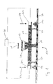
- Fig. 1 shows a switch 11 according to the invention with two switching elements 13a and 13b and a rocker switch 15.
- the rocker switch 15 is rotatably mounted at a pivot point 17 and has an actuating element 19.
- On the rocker switch 15 a plurality of sensors 21 are arranged.
- the sensors 21a and 21b are located above the switching elements 13a and 13b, respectively, and respond to a pushing movement, respectively is shown by arrows 23a and 23b.
- the sensor 21c is mounted on or integrated with the actuator 19 and is responsive to a push / pull movement represented by an arrow 25.
- the switch 11 also has two springs 27 which are attached to the rocker switch 15 and, for example, to a housing wall 29 of the switch.
- the springs 27 press the rocker switch 15 in a neutral position, in which none of the switching elements 13a and 13b is actuated.
- the neutral position is thus defined by means of the springs 27 as the default position of the switch, which is set automatically when no force acts on the switch. This is particularly advantageous when only a short-term actuation of the switching elements 13a and 13b is desired or required.
- a sensor signal is generated by the corresponding sensor and sent to a control unit 30.
- the control unit 30 assigns the sensor signal to one of the switching elements 13a or 13b, activates it and deactivates further switching elements.
- the control unit 30 activates the switching element 13a and deactivates the switching element 13b.
- the sensor 21c determines in which direction the sliding / pulling movement takes place and assigns this movement to the corresponding switching element, for example the switching element 13b, and activates this, while the further switching element 13a is deactivated.
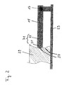
- Fig. 2 shows a particular embodiment of the switch of Fig. 1 , wherein only the left side of the rocker switch 15 is shown by way of example, which is mounted at the pivot point 17.
- the switching rocker 15 has on its left side a locking element 31, which has a spring 33 and a ball 35.
- the ball 35 can engage in recesses 37, which are provided for example in a housing portion 39 of the switch.
- the rocker switch reaches a predetermined position, it can thus be fixed by means of the ball 35 in this position.
- defined switching states and a haptic can be defined, ie the user of the switch 11 can detect the switching states with his sense of touch.
- the recesses 37 are formed differently deep, so that the user of the switch 11 can distinguish by means of the sense of touch between different switching states.
Priority Applications (1)
| Application Number | Priority Date | Filing Date | Title |
|---|---|---|---|
| EP20080017964 EP2178098B1 (fr) | 2008-10-14 | 2008-10-14 | Interrupteur |
Applications Claiming Priority (1)
| Application Number | Priority Date | Filing Date | Title |
|---|---|---|---|
| EP20080017964 EP2178098B1 (fr) | 2008-10-14 | 2008-10-14 | Interrupteur |
Publications (2)
| Publication Number | Publication Date |
|---|---|
| EP2178098A1 true EP2178098A1 (fr) | 2010-04-21 |
| EP2178098B1 EP2178098B1 (fr) | 2012-05-30 |
Family
ID=40383894
Family Applications (1)
| Application Number | Title | Priority Date | Filing Date |
|---|---|---|---|
| EP20080017964 Active EP2178098B1 (fr) | 2008-10-14 | 2008-10-14 | Interrupteur |
Country Status (1)
| Country | Link |
|---|---|
| EP (1) | EP2178098B1 (fr) |
Cited By (3)
| Publication number | Priority date | Publication date | Assignee | Title |
|---|---|---|---|---|
| DE102010042524A1 (de) * | 2010-10-15 | 2012-04-19 | Siemens Aktiengesellschaft | Tragbares Gerät mit Bedieneinheit |
| ITBZ20120005A1 (it) * | 2012-02-10 | 2013-08-11 | Alpgate S R L | Interruttore a bilico |
| DE102016118459A1 (de) | 2016-09-29 | 2018-03-29 | Jungheinrich Aktiengesellschaft | Flurförderzeug mit einem einen Bedienhebel aufweisenden Bedienmittel sowie Verfahren zur Bedienung eines solchen Flurförderzeugs |
Citations (3)
| Publication number | Priority date | Publication date | Assignee | Title |
|---|---|---|---|---|
| DE20103570U1 (de) * | 2001-02-23 | 2001-05-03 | Ludwig Manfred | Einzeltaste mit Druckschalter zur Fehlbedienungssicherung |
| DE10027484C1 (de) * | 2000-06-02 | 2001-12-20 | Kostal Leopold Gmbh & Co Kg | Kipp-Schiebe-Schalter |
| DE102005005185A1 (de) * | 2005-02-03 | 2006-08-17 | Daimlerchrysler Ag | Schaltanordnung für ein Schaltelement zum Öffnen und Schließen eines Fahrzeugflügels |
-
2008
- 2008-10-14 EP EP20080017964 patent/EP2178098B1/fr active Active
Patent Citations (3)
| Publication number | Priority date | Publication date | Assignee | Title |
|---|---|---|---|---|
| DE10027484C1 (de) * | 2000-06-02 | 2001-12-20 | Kostal Leopold Gmbh & Co Kg | Kipp-Schiebe-Schalter |
| DE20103570U1 (de) * | 2001-02-23 | 2001-05-03 | Ludwig Manfred | Einzeltaste mit Druckschalter zur Fehlbedienungssicherung |
| DE102005005185A1 (de) * | 2005-02-03 | 2006-08-17 | Daimlerchrysler Ag | Schaltanordnung für ein Schaltelement zum Öffnen und Schließen eines Fahrzeugflügels |
Cited By (6)
| Publication number | Priority date | Publication date | Assignee | Title |
|---|---|---|---|---|
| DE102010042524A1 (de) * | 2010-10-15 | 2012-04-19 | Siemens Aktiengesellschaft | Tragbares Gerät mit Bedieneinheit |
| DE102010042524B4 (de) * | 2010-10-15 | 2012-08-02 | Siemens Aktiengesellschaft | Tragbares Gerät mit Bedieneinheit |
| US9824833B2 (en) | 2010-10-15 | 2017-11-21 | Siemens Aktiengesellschaft | Appliance comprising an operating unit |
| ITBZ20120005A1 (it) * | 2012-02-10 | 2013-08-11 | Alpgate S R L | Interruttore a bilico |
| DE102016118459A1 (de) | 2016-09-29 | 2018-03-29 | Jungheinrich Aktiengesellschaft | Flurförderzeug mit einem einen Bedienhebel aufweisenden Bedienmittel sowie Verfahren zur Bedienung eines solchen Flurförderzeugs |
| US10664003B2 (en) | 2016-09-29 | 2020-05-26 | Jungheinrich Aktiengesellschaft | Industrial truck with operating assembly and associated method |
Also Published As
| Publication number | Publication date |
|---|---|
| EP2178098B1 (fr) | 2012-05-30 |
Similar Documents
| Publication | Publication Date | Title |
|---|---|---|
| EP1512814B1 (fr) | Système de verrouillage pour une porte de véhicule automobile et une poignée | |
| EP2333208B1 (fr) | Serrure de véhicule automobile | |
| DE102010024776B4 (de) | Vorrichtung zur Bedienung mehrerer Funktionen in einem Kraftfahrzeug | |
| EP3486931B1 (fr) | Commutateur à effleurement et véhicule automobile doté d'un commutateur à effleurement | |
| EP3594044B1 (fr) | Système capacitif de commande de véhicule automobile | |
| EP3739155B1 (fr) | Agencement de poignée de porte | |
| EP1758135B1 (fr) | Dispositif interrupteur | |
| EP2178098B1 (fr) | Interrupteur | |
| EP2647126B1 (fr) | Unité de commande, en particulier pour un composant de véhicule | |
| DE102018204351A1 (de) | Türverriegelungseinrichtung für ein Kraftfahrzeug | |
| WO2016096099A1 (fr) | Dispositif de commande pour véhicule, en particulier pour un véhicule automobile | |
| EP3149263A1 (fr) | Poignée de portière pour véhicule automobile | |
| DE102009053717B4 (de) | Anordnung mit einem Sicherheitsschalter oder einer Sicherheitszuhaltung und einem mechanischen Betätiger | |
| EP3388276B1 (fr) | Dispositif de commande d'au moins un appareil électrique au moyen d'un capteur de force, système d'aide à la conduite, véhicule ainsi que procédé de commande d'un dispositif de commande | |
| DE102012019387A1 (de) | Druck- und drehbetätigbares Bedienelement für ein Kraftfahrzeug | |
| EP2099991B1 (fr) | Mecanisme de fermeture de porte de vehicule | |
| DE10312226B4 (de) | Taste für sicherheitsgerichtete Schaltprozesse | |
| DE102018120074A1 (de) | Schließsystem | |
| DE102009008537B3 (de) | Drucktaster | |
| EP2972644A1 (fr) | Unité d'entrée pour un élément de commande pouvant être actionné par pression et par rotation | |
| EP1849950A2 (fr) | Ensemble de porte coulissante | |
| DE102021207689A1 (de) | Einrichtung zum Öffnen einer Fahrzeugtür und Fahrzeug mit einer solchen Einrichtung | |
| DE102016201669B3 (de) | Funktionstaste | |
| DE102020000771A1 (de) | Bedienvorrichtung für ein Fahrzeug | |
| DE102009005283B4 (de) | Druck- und drehbetätigbares Bedienelement für ein Kraftfahrzeug |
Legal Events
| Date | Code | Title | Description |
|---|---|---|---|
| PUAI | Public reference made under article 153(3) epc to a published international application that has entered the european phase |
Free format text: ORIGINAL CODE: 0009012 |
|
| AK | Designated contracting states |
Kind code of ref document: A1 Designated state(s): AT BE BG CH CY CZ DE DK EE ES FI FR GB GR HR HU IE IS IT LI LT LU LV MC MT NL NO PL PT RO SE SI SK TR |
|
| AX | Request for extension of the european patent |
Extension state: AL BA MK RS |
|
| 17P | Request for examination filed |
Effective date: 20100615 |
|
| AKX | Designation fees paid |
Designated state(s): AT BE BG CH CY CZ DE DK EE ES FI FR GB GR HR HU IE IS IT LI LT LU LV MC MT NL NO PL PT RO SE SI SK TR |
|
| GRAP | Despatch of communication of intention to grant a patent |
Free format text: ORIGINAL CODE: EPIDOSNIGR1 |
|
| GRAS | Grant fee paid |
Free format text: ORIGINAL CODE: EPIDOSNIGR3 |
|
| GRAA | (expected) grant |
Free format text: ORIGINAL CODE: 0009210 |
|
| AK | Designated contracting states |
Kind code of ref document: B1 Designated state(s): AT BE BG CH CY CZ DE DK EE ES FI FR GB GR HR HU IE IS IT LI LT LU LV MC MT NL NO PL PT RO SE SI SK TR |
|
| REG | Reference to a national code |
Ref country code: GB Ref legal event code: FG4D Free format text: NOT ENGLISH |
|
| REG | Reference to a national code |
Ref country code: CH Ref legal event code: EP |
|
| REG | Reference to a national code |
Ref country code: AT Ref legal event code: REF Ref document number: 560399 Country of ref document: AT Kind code of ref document: T Effective date: 20120615 |
|
| REG | Reference to a national code |
Ref country code: IE Ref legal event code: FG4D Free format text: LANGUAGE OF EP DOCUMENT: GERMAN |
|
| REG | Reference to a national code |
Ref country code: DE Ref legal event code: R096 Ref document number: 502008007294 Country of ref document: DE Effective date: 20120802 |
|
| REG | Reference to a national code |
Ref country code: NL Ref legal event code: VDEP Effective date: 20120530 |
|
| REG | Reference to a national code |
Ref country code: LT Ref legal event code: MG4D Effective date: 20120530 |
|
| PG25 | Lapsed in a contracting state [announced via postgrant information from national office to epo] |
Ref country code: CY Free format text: LAPSE BECAUSE OF FAILURE TO SUBMIT A TRANSLATION OF THE DESCRIPTION OR TO PAY THE FEE WITHIN THE PRESCRIBED TIME-LIMIT Effective date: 20120530 Ref country code: NO Free format text: LAPSE BECAUSE OF FAILURE TO SUBMIT A TRANSLATION OF THE DESCRIPTION OR TO PAY THE FEE WITHIN THE PRESCRIBED TIME-LIMIT Effective date: 20120830 Ref country code: SE Free format text: LAPSE BECAUSE OF FAILURE TO SUBMIT A TRANSLATION OF THE DESCRIPTION OR TO PAY THE FEE WITHIN THE PRESCRIBED TIME-LIMIT Effective date: 20120530 Ref country code: LT Free format text: LAPSE BECAUSE OF FAILURE TO SUBMIT A TRANSLATION OF THE DESCRIPTION OR TO PAY THE FEE WITHIN THE PRESCRIBED TIME-LIMIT Effective date: 20120530 Ref country code: IS Free format text: LAPSE BECAUSE OF FAILURE TO SUBMIT A TRANSLATION OF THE DESCRIPTION OR TO PAY THE FEE WITHIN THE PRESCRIBED TIME-LIMIT Effective date: 20120930 Ref country code: FI Free format text: LAPSE BECAUSE OF FAILURE TO SUBMIT A TRANSLATION OF THE DESCRIPTION OR TO PAY THE FEE WITHIN THE PRESCRIBED TIME-LIMIT Effective date: 20120530 |
|
| PG25 | Lapsed in a contracting state [announced via postgrant information from national office to epo] |
Ref country code: SI Free format text: LAPSE BECAUSE OF FAILURE TO SUBMIT A TRANSLATION OF THE DESCRIPTION OR TO PAY THE FEE WITHIN THE PRESCRIBED TIME-LIMIT Effective date: 20120530 Ref country code: LV Free format text: LAPSE BECAUSE OF FAILURE TO SUBMIT A TRANSLATION OF THE DESCRIPTION OR TO PAY THE FEE WITHIN THE PRESCRIBED TIME-LIMIT Effective date: 20120530 Ref country code: HR Free format text: LAPSE BECAUSE OF FAILURE TO SUBMIT A TRANSLATION OF THE DESCRIPTION OR TO PAY THE FEE WITHIN THE PRESCRIBED TIME-LIMIT Effective date: 20120530 Ref country code: GR Free format text: LAPSE BECAUSE OF FAILURE TO SUBMIT A TRANSLATION OF THE DESCRIPTION OR TO PAY THE FEE WITHIN THE PRESCRIBED TIME-LIMIT Effective date: 20120831 |
|
| PG25 | Lapsed in a contracting state [announced via postgrant information from national office to epo] |
Ref country code: SK Free format text: LAPSE BECAUSE OF FAILURE TO SUBMIT A TRANSLATION OF THE DESCRIPTION OR TO PAY THE FEE WITHIN THE PRESCRIBED TIME-LIMIT Effective date: 20120530 Ref country code: CZ Free format text: LAPSE BECAUSE OF FAILURE TO SUBMIT A TRANSLATION OF THE DESCRIPTION OR TO PAY THE FEE WITHIN THE PRESCRIBED TIME-LIMIT Effective date: 20120530 Ref country code: NL Free format text: LAPSE BECAUSE OF FAILURE TO SUBMIT A TRANSLATION OF THE DESCRIPTION OR TO PAY THE FEE WITHIN THE PRESCRIBED TIME-LIMIT Effective date: 20120530 Ref country code: EE Free format text: LAPSE BECAUSE OF FAILURE TO SUBMIT A TRANSLATION OF THE DESCRIPTION OR TO PAY THE FEE WITHIN THE PRESCRIBED TIME-LIMIT Effective date: 20120530 Ref country code: RO Free format text: LAPSE BECAUSE OF FAILURE TO SUBMIT A TRANSLATION OF THE DESCRIPTION OR TO PAY THE FEE WITHIN THE PRESCRIBED TIME-LIMIT Effective date: 20120530 Ref country code: DK Free format text: LAPSE BECAUSE OF FAILURE TO SUBMIT A TRANSLATION OF THE DESCRIPTION OR TO PAY THE FEE WITHIN THE PRESCRIBED TIME-LIMIT Effective date: 20120530 |
|
| PG25 | Lapsed in a contracting state [announced via postgrant information from national office to epo] |
Ref country code: PT Free format text: LAPSE BECAUSE OF FAILURE TO SUBMIT A TRANSLATION OF THE DESCRIPTION OR TO PAY THE FEE WITHIN THE PRESCRIBED TIME-LIMIT Effective date: 20121001 Ref country code: PL Free format text: LAPSE BECAUSE OF FAILURE TO SUBMIT A TRANSLATION OF THE DESCRIPTION OR TO PAY THE FEE WITHIN THE PRESCRIBED TIME-LIMIT Effective date: 20120530 |
|
| PLBE | No opposition filed within time limit |
Free format text: ORIGINAL CODE: 0009261 |
|
| STAA | Information on the status of an ep patent application or granted ep patent |
Free format text: STATUS: NO OPPOSITION FILED WITHIN TIME LIMIT |
|
| BERE | Be: lapsed |
Owner name: DELPHI TECHNOLOGIES, INC. Effective date: 20121031 |
|
| PG25 | Lapsed in a contracting state [announced via postgrant information from national office to epo] |
Ref country code: ES Free format text: LAPSE BECAUSE OF FAILURE TO SUBMIT A TRANSLATION OF THE DESCRIPTION OR TO PAY THE FEE WITHIN THE PRESCRIBED TIME-LIMIT Effective date: 20120910 |
|
| 26N | No opposition filed |
Effective date: 20130301 |
|
| PG25 | Lapsed in a contracting state [announced via postgrant information from national office to epo] |
Ref country code: MC Free format text: LAPSE BECAUSE OF NON-PAYMENT OF DUE FEES Effective date: 20121031 |
|
| REG | Reference to a national code |
Ref country code: CH Ref legal event code: PL |
|
| GBPC | Gb: european patent ceased through non-payment of renewal fee |
Effective date: 20121014 |
|
| REG | Reference to a national code |
Ref country code: DE Ref legal event code: R097 Ref document number: 502008007294 Country of ref document: DE Effective date: 20130301 |
|
| REG | Reference to a national code |
Ref country code: IE Ref legal event code: MM4A |
|
| PG25 | Lapsed in a contracting state [announced via postgrant information from national office to epo] |
Ref country code: GB Free format text: LAPSE BECAUSE OF NON-PAYMENT OF DUE FEES Effective date: 20121014 Ref country code: CH Free format text: LAPSE BECAUSE OF NON-PAYMENT OF DUE FEES Effective date: 20121031 Ref country code: LI Free format text: LAPSE BECAUSE OF NON-PAYMENT OF DUE FEES Effective date: 20121031 Ref country code: BE Free format text: LAPSE BECAUSE OF NON-PAYMENT OF DUE FEES Effective date: 20121031 Ref country code: IE Free format text: LAPSE BECAUSE OF NON-PAYMENT OF DUE FEES Effective date: 20121014 Ref country code: BG Free format text: LAPSE BECAUSE OF FAILURE TO SUBMIT A TRANSLATION OF THE DESCRIPTION OR TO PAY THE FEE WITHIN THE PRESCRIBED TIME-LIMIT Effective date: 20120830 |
|
| PG25 | Lapsed in a contracting state [announced via postgrant information from national office to epo] |
Ref country code: MT Free format text: LAPSE BECAUSE OF FAILURE TO SUBMIT A TRANSLATION OF THE DESCRIPTION OR TO PAY THE FEE WITHIN THE PRESCRIBED TIME-LIMIT Effective date: 20120530 |
|
| REG | Reference to a national code |
Ref country code: FR Ref legal event code: TP Owner name: DELPHI INTERNATIONAL OPERATIONS LUXEMBOURG S.A, LU Effective date: 20131218 |
|
| PG25 | Lapsed in a contracting state [announced via postgrant information from national office to epo] |
Ref country code: TR Free format text: LAPSE BECAUSE OF FAILURE TO SUBMIT A TRANSLATION OF THE DESCRIPTION OR TO PAY THE FEE WITHIN THE PRESCRIBED TIME-LIMIT Effective date: 20120530 |
|
| PG25 | Lapsed in a contracting state [announced via postgrant information from national office to epo] |
Ref country code: LU Free format text: LAPSE BECAUSE OF NON-PAYMENT OF DUE FEES Effective date: 20121014 |
|
| PG25 | Lapsed in a contracting state [announced via postgrant information from national office to epo] |
Ref country code: HU Free format text: LAPSE BECAUSE OF FAILURE TO SUBMIT A TRANSLATION OF THE DESCRIPTION OR TO PAY THE FEE WITHIN THE PRESCRIBED TIME-LIMIT Effective date: 20081014 |
|
| REG | Reference to a national code |
Ref country code: AT Ref legal event code: MM01 Ref document number: 560399 Country of ref document: AT Kind code of ref document: T Effective date: 20131014 |
|
| PG25 | Lapsed in a contracting state [announced via postgrant information from national office to epo] |
Ref country code: AT Free format text: LAPSE BECAUSE OF NON-PAYMENT OF DUE FEES Effective date: 20131014 |
|
| REG | Reference to a national code |
Ref country code: FR Ref legal event code: PLFP Year of fee payment: 8 |
|
| REG | Reference to a national code |
Ref country code: FR Ref legal event code: PLFP Year of fee payment: 9 |
|
| REG | Reference to a national code |
Ref country code: FR Ref legal event code: PLFP Year of fee payment: 10 |
|
| REG | Reference to a national code |
Ref country code: FR Ref legal event code: PLFP Year of fee payment: 11 |
|
| REG | Reference to a national code |
Ref country code: DE Ref legal event code: R081 Ref document number: 502008007294 Country of ref document: DE Owner name: APTIV TECHNOLOGIES LIMITED, BB Free format text: FORMER OWNER: DELPHI TECHNOLOGIES, INC., TROY, MICH., US |
|
| PGFP | Annual fee paid to national office [announced via postgrant information from national office to epo] |
Ref country code: IT Payment date: 20191023 Year of fee payment: 12 Ref country code: FR Payment date: 20191025 Year of fee payment: 12 |
|
| PG25 | Lapsed in a contracting state [announced via postgrant information from national office to epo] |
Ref country code: FR Free format text: LAPSE BECAUSE OF NON-PAYMENT OF DUE FEES Effective date: 20201031 |
|
| PG25 | Lapsed in a contracting state [announced via postgrant information from national office to epo] |
Ref country code: IT Free format text: LAPSE BECAUSE OF NON-PAYMENT OF DUE FEES Effective date: 20201014 |
|
| P01 | Opt-out of the competence of the unified patent court (upc) registered |
Effective date: 20230425 |
|
| PGFP | Annual fee paid to national office [announced via postgrant information from national office to epo] |
Ref country code: DE Payment date: 20231017 Year of fee payment: 16 |