EP2177371B1 - Dokumentverarbeitungsmaschine mit verbessertem Antriebssystem - Google Patents
Dokumentverarbeitungsmaschine mit verbessertem Antriebssystem Download PDFInfo
- Publication number
- EP2177371B1 EP2177371B1 EP20090172795 EP09172795A EP2177371B1 EP 2177371 B1 EP2177371 B1 EP 2177371B1 EP 20090172795 EP20090172795 EP 20090172795 EP 09172795 A EP09172795 A EP 09172795A EP 2177371 B1 EP2177371 B1 EP 2177371B1
- Authority
- EP
- European Patent Office
- Prior art keywords
- shaft
- drive
- drive member
- wall
- cam
- Prior art date
- Legal status (The legal status is an assumption and is not a legal conclusion. Google has not performed a legal analysis and makes no representation as to the accuracy of the status listed.)
- Not-in-force
Links
- 238000005520 cutting process Methods 0.000 claims description 38
- 230000007246 mechanism Effects 0.000 claims description 30
- 230000000694 effects Effects 0.000 claims description 3
- 230000008859 change Effects 0.000 claims description 2
- 230000000295 complement effect Effects 0.000 description 3
- 238000006073 displacement reaction Methods 0.000 description 3
- 230000008901 benefit Effects 0.000 description 2
- 230000008878 coupling Effects 0.000 description 2
- 238000010168 coupling process Methods 0.000 description 2
- 238000005859 coupling reaction Methods 0.000 description 2
- 238000000605 extraction Methods 0.000 description 2
- 238000011144 upstream manufacturing Methods 0.000 description 2
- 230000006835 compression Effects 0.000 description 1
- 238000007906 compression Methods 0.000 description 1
- 238000010586 diagram Methods 0.000 description 1
- 229920001971 elastomer Polymers 0.000 description 1
- 239000000806 elastomer Substances 0.000 description 1
- 230000002452 interceptive effect Effects 0.000 description 1
- 238000004519 manufacturing process Methods 0.000 description 1
Images





Classifications
-
- B—PERFORMING OPERATIONS; TRANSPORTING
- B43—WRITING OR DRAWING IMPLEMENTS; BUREAU ACCESSORIES
- B43M—BUREAU ACCESSORIES NOT OTHERWISE PROVIDED FOR
- B43M7/00—Devices for opening envelopes
- B43M7/005—Devices for opening envelopes with at least two cutting discs
-
- Y—GENERAL TAGGING OF NEW TECHNOLOGICAL DEVELOPMENTS; GENERAL TAGGING OF CROSS-SECTIONAL TECHNOLOGIES SPANNING OVER SEVERAL SECTIONS OF THE IPC; TECHNICAL SUBJECTS COVERED BY FORMER USPC CROSS-REFERENCE ART COLLECTIONS [XRACs] AND DIGESTS
- Y10—TECHNICAL SUBJECTS COVERED BY FORMER USPC
- Y10T—TECHNICAL SUBJECTS COVERED BY FORMER US CLASSIFICATION
- Y10T83/00—Cutting
- Y10T83/202—With product handling means
- Y10T83/2092—Means to move, guide, or permit free fall or flight of product
-
- Y—GENERAL TAGGING OF NEW TECHNOLOGICAL DEVELOPMENTS; GENERAL TAGGING OF CROSS-SECTIONAL TECHNOLOGIES SPANNING OVER SEVERAL SECTIONS OF THE IPC; TECHNICAL SUBJECTS COVERED BY FORMER USPC CROSS-REFERENCE ART COLLECTIONS [XRACs] AND DIGESTS
- Y10—TECHNICAL SUBJECTS COVERED BY FORMER USPC
- Y10T—TECHNICAL SUBJECTS COVERED BY FORMER US CLASSIFICATION
- Y10T83/00—Cutting
- Y10T83/727—With means to guide moving work
- Y10T83/741—With movable or yieldable guide element
-
- Y—GENERAL TAGGING OF NEW TECHNOLOGICAL DEVELOPMENTS; GENERAL TAGGING OF CROSS-SECTIONAL TECHNOLOGIES SPANNING OVER SEVERAL SECTIONS OF THE IPC; TECHNICAL SUBJECTS COVERED BY FORMER USPC CROSS-REFERENCE ART COLLECTIONS [XRACs] AND DIGESTS
- Y10—TECHNICAL SUBJECTS COVERED BY FORMER USPC
- Y10T—TECHNICAL SUBJECTS COVERED BY FORMER US CLASSIFICATION
- Y10T83/00—Cutting
- Y10T83/768—Rotatable disc tool pair or tool and carrier
Definitions
- the invention concerns a document processing machine.
- Machines are known for processing documents such as envelopes in which a portion of the documents is cut off.
- Machines in which the documents are envelopes are commonly called "envelope-openers".
- the envelopes 12 are driven one by one, for example by belts 14a, 14b, 14c, in a movement of longitudinal displacement along the axis XX' on the surface of a horizontal table 16 forming a support.
- US-A-2003/041561 discloses a document processing machine according to the preamble of claim 1.
- the envelopes are guided along a longitudinal wall 18 disposed on one side of the table 16.
- a device 20 for cutting off a portion of the envelopes, in particular one of the edges thereof, is disposed along the table, aligned with the guide wall 18, to be in contact with the portion of each envelope to be cut off.
- the cutter device 20 is shown diagrammatically in cross section in figure 2 .
- It comprises a lower cutter 22 and an upper cutter 24 which have cutting edges 22a, 24a arranged adjacent to each other.
- the cutters are mounted to rotate about respective horizontal axes 22b, 24b perpendicular to the longitudinal direction XX' of movement of the envelopes.
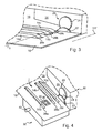
- FIG 3 shows diagrammatically in perspective the arrangement of the guide wall 18 and the cutter device 20 on one of the longitudinal sides of the table 16 and the belts 14a-14c.
- the belts project above the table 16 through respective apertures 28a-c formed in the thickness of the table.
- the cutter device is disposed in a fixed wall 26 fastened to the frame of the machine.
- the guide wall 18 placed at the upstream end of the cutter device is adapted to be moved laterally along the transverse axis YY' to position the document to be cut between the cutters 22 and 24, in a number of possible cutting positions.
- the belts 14a-c route the document of which a portion is to be cut off on the table 16 and along the wall 18 to the cutter device.
- the belts descend below the table 16 at a location thereof corresponding to a longitudinal position along the axis XX' represented by the reference Po.
- This position Po is upstream of the longitudinal position at which the document is engaged between the cutters.
- the belts are arranged so that they do not continue to drive a document that is already engaged in the cutter device.
- the Applicant has realized that it could be useful to be able to feed a document in such machines without cutting it.
- the Applicant has made provision for moving the guide wall 18 into an extreme lateral position (non-cutting position). In this position the wall is offset laterally in the direction of the table 16 so that the cutter device is no longer aligned with the wall when moved in this way.
- the belts 14a-c can no longer route documents downstream of the position Po in figure 3 .
- the cutter device which at this point used to take over to drive the documents to be cut in the downstream direction, is bypassed and can no longer act on the documents.
- the Applicant has nevertheless provided at least one drive member that is mobile between a rest position and a driving position, in which latter position it drives a document in the downstream direction when the guide wall has simultaneously been moved to the non-cutting position and the conventional driving means (for example belts) are ineffective.
- one particular object of the invention is a document processing machine comprising
- said at least one drive member is adapted to be placed in its driving position when the wall is in a non-cutting position in order to drive in the downstream direction documents routed by the table and not cut.
- the machine includes a mechanism for moving the longitudinal wall that is connected to a mechanism for moving said at least one drive member.
- This arrangement ensures that the two movements, that of the wall and that of said at least one drive member, are linked and therefore that the one cannot take place without the other.
- the machine includes a single drive system for simultaneously driving the movement of the wall and the movement of said at least one drive member, which is particularly convenient and simple for the user.
- independent driving systems can be envisaged instead, driving each of the movements independently, according to what is required, the arrangement of the machine and the applications.
- the machine includes a drive shaft connected to the wall and that is adapted to be driven in rotation about its shaft, the shaft being provided with a contact member that cooperates with a cam fastened to the wall during movement in rotation of the shaft in order to move the wall.
- This particularly simple mechanism moves the document guide wall to the extreme lateral position of that wall referred to as the non-cutting position.
- the contact member is at one end of the shaft and said shaft has at its opposite end a toothed pulley for driving the shaft in rotation.
- said at least one drive member is adapted to effect a pivoting movement between a retracted rest position and a deployed driving position.
- said at least one drive member is set back from the path followed by the documents, in a rest position that is, for example below the level of the document routing table. It is extracted from that position to occupy a deployed driving position, for example above the routing table, in order to drive in the downstream direction a document that will not be processed by the cutter device.
- said at least one drive member is mounted to pivot about a first reference shaft, the pivoting being driven by the movement of a drive shaft connected to said at least one drive member and which extends relative thereto parallel to the first reference shaft.
- the pivoting movement of said at least one drive member is controlled in a simple manner by this drive shaft connected to said at least one member.
- said at least one drive member is connected to the first reference shaft by a connecting part pivotally mounted on said first reference shaft, the drive shaft being attached to the connecting part.
- the drive shaft cooperates with a mobile cam movement whereof drives movement of said drive shaft.
- Actuation of this cam thus provides an easy way to drive the pivoting of said at least one drive member.
- the cam is mounted to rotate about a second reference shaft attached to the machine.
- the cam has two opposite faces, a first or internal face provided with a cam surface for cooperation with the drive shaft of said at least one drive member and an opposite second or external face that is provided with a drive member for driving movement of the cam.
- the cam carries a manual control knob for moving it.
- This knob serves as a drive member and is easily accessible to the user because it is situated on the external face of the cam facing away from the machine.
- the cam is provided with a toothed pulley for driving its movement.
- This pulley serves as an intermediate drive member used in cooperation with another intermediate drive member forming part of the mechanism for moving the longitudinal wall.
- an elongate connecting member for example a ribbed belt, runs around the two toothed pulleys, that of the mechanism for moving said at least one drive member and that of the mechanism for moving the longitudinal wall, in order to link the rotation movements of the two pulleys to each other.
- This connection therefore links together the movements of two mechanisms for moving the wall and said at least one drive member via their respective intermediate drive members.
- said at least one drive member is driven in rotation on itself by drive means.
- These drive means are partly mounted on the first reference shaft.
- these drive means are in part mounted on the connecting part connected to said at least one drive member and pivotally mounted on the first reference shaft.
- these rotation drive means take the form of an intermediate gear meshing with a gear attached to the first reference shaft and a gear associated with said at least one pivot member.
- elastic means are coupled to said at least one mobile drive member so that, in the driving position of the latter member, said spring means exert an elastic force tending to hold said at least one drive member in that position.
- the elastic means comprise a return spring which, through the force that it exerts on said at least one drive member in its driving position, exerts pressure on the document that will be in contact with said at least one drive member.
- an additional drive member is arranged in a fixed position above said at least one mobile drive member and is adapted to cooperate therewith to pinch a document between said mobile and fixed drive members when said at least one drive member is in its driving position.
- This additional drive member takes the form of a counter-roller, for example.
- the document routing table includes document routing means adapted to route documents toward the downstream end of the machine along the longitudinal wall when the wall is in a cutting position, said at least one driving member then being in its rest position.
- the conventional means for routing documents along the wall convey them to the cutter device without said at least one drive member intervening.
- Said at least one drive member is actuated when the cutter device is de-activated by the extreme lateral displacement of the longitudinal wall in the non-cutting position.
- the document processing machine of the invention includes the components already described with reference to figures 1 to 3 and their description will therefore not be repeated here.
- the machine 30 includes under the document routing table 16 a system 32 that drives the documents routed on the table when the cutter device 20 is de-activated, following appropriate lateral movement of the wall 18 that guides the documents.
- a window 35 is formed through the thickness of the table 16 to enable deployment above or retraction below the table, on command, of one or more document drive members to be activated or de-activated as a function of the lateral position of the wall 18.
- the window 35 is positioned at a lateral distance from the wall 18 that is sufficient for the drive member protruding from this window to be in contact with documents (e.g. envelopes) of varied widths when the wall is in the non-cutting position.
- documents e.g. envelopes
- This window 35 is disposed between two apertures through which the document transport belts pass.
- the window 35 is placed between the two apertures at the greatest distance from the guide wall 18, namely the apertures 28a and 28b.
- Figure 5 is a diagrammatic view of the figure 4 system 32 after removing the table 16, the belts 14a to 14c, and the pulleys on which they are mounted.
- the system 32 includes a plate 34 fixed to the frame 30 of the machine.
- the system 32 further includes a number of mechanisms attached to the plate, one of which drives movement of one or more document drive members and the other of which drives movement of the guide wall 18.
- the machine more particularly includes a mechanism 38 for moving the wall 18 described with reference to figures 6 and 7 .
- the machine also includes a mechanism 40 for moving the drive member 36.
- these mechanisms can be operated by a single control which is represented here by a manual control member such as a knob 42 ( figure 5 ).
- each of the mechanisms 38 and 40 can be actuated independently, for example, by an appropriate mechanical control member, adapted to each of the mechanisms.
- each of these members can be controlled electronically using document detector means.
- document detector means such as a photo-electric cell that detects the passage of a document in front of it, send a pulse to an electronic control system which then actuates each of the aforementioned mechanisms.
- This photo-electric cell can advantageously also be used to count the documents by means of an appropriate processor electronic circuit downstream.
- a motor 44 is arranged alongside the plate 34. It is also fixed to the frame of the machine and has an output shaft 46.
- a drive belt 48 wraps, on the one hand, around the output shaft 46 of the motor and, on the other hand, around another shaft 50, thus communicating a rotation movement to that shaft.
- belt 48 is mounted on the shafts 46 and 50 by means of respective pulleys.
- the driven shaft 50 is aligned with a first reference shaft A1 and a number of members are mounted to rotate about this reference shaft A1, including the pulley 51 around which the belt 48 wraps.
- the drive means that have just been described drive movement of the document routing belts and therefore the documents themselves.
- first reference shaft also carries a toothed ring 58 that forms part of the drive means for the drive member 36 (see below).
- This ring in fact drives the member 36 in rotation on itself to drive the documents.
- the first shaft A1 also carries a toothed gear 59 fastened to the pulley 51 and meshing with a gear 57 ( figure 12 ) carried by the shaft on which the upper cutter 24 is mounted in order to drive the latter in rotation.
- the aforementioned document routing means route the documents toward the downstream end of the machine in the direction indicated by the arrow F in figure 4 when the longitudinal wall 18 is in a cutting position 18 (C) shown in dotted line in figure 7 .
- Figure 7 also shows the lower cutter 22 of the cutter device, the wall 18 in this position driving a document until it comes into contact with this cutter for the cutting operation.
- the mechanism 38 for moving the wall 18 includes a drive shaft 60 that is connected to the wall 18, for example at one of its longitudinal ends.
- This shaft can be driven in rotation about its shaft as indicated by the arrow in figure 6 .
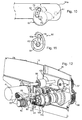
- the shaft 60 is provided at its opposite longitudinal end with a toothed pulley 62 that can be seen in figures 5 and 12 .
- Figure 6 shows diagrammatically the connection between the drive shaft 60 and the wall 18.
- the shaft 60 is provided with an actuator member 64 that cooperates with a cam 66 attached to the wall.
- This cam has on its surface a number of intermediate stop positions, of which two positions 66a and 66b are shown in figure 6 .
- the actuator member 64 which takes the form of an actuator finger, for example, moves over the surface of the cam 66 and takes up a position in one of the recesses thereof, for example the recess 66a in figure 6 .
- This stop position corresponds, for example, to a cutting position of the wall such as the position 18 (C) shown in figure 7 .
- this actuator member continues its movement in contact with the surface of the cam 66 and then takes up a position in the next recess 66b, thus moving the wall into an extreme lateral or non-cutting position 18 (NC) shown in figure 7 .
- the wall 18 is offset relative to its position 18(C) and a document routed along this wall then passes in front of the lower cutter 22 instead of passing over it, thus avoiding the cutting operation.
- Figure 6 shows more specifically the presence in the lower portion of the wall 18 of an offset edge 18a that forms a lateral step relative thereto, to which a plate 68 fitted with the cam 66 is fixed.
- This cam takes the form of a wall extending from one of its ends from the large free face of the plate 68 and progressively moving away from the latter along the start of a spiral trajectory.
- This position 66c corresponds to a cutting position of the wall 18 different from that shown in figure 7 , producing a different document cutting width.
- Figure 7 shows very diagrammatically the offset edge 18a forming a step and in dashed line a first position of the actuator member 64 when it is located in the recess 66a and a second position of this member when it occupies the next recess 66b, these two positions being situated at 90° to each other.
- a spring 65 is placed between, on the one hand, the free face of the offset edge 18a opposite that on which the plate 68 is disposed and, on the other hand, a portion of the plate facing said free face ( figures 5 and 12 ).
- This spring maintains permanent contact between the member 64 and one of the recesses 66a-c.
- a part 69 (for example a screw) serves as a stop for the lateral movement of the wall 18, thus defining the maximum cutting width.
- This member is mounted in the machine 30 so that it can pivot about the first reference shaft A1 between a retracted or rest position shown in figures 4 and 15 and a deployed active or driving position shown in figure 16 .
- the pivoting movement of the member 36 about the pivot shaft A1 is driven by controlling the movement of a drive shaft 70 shown in figures 8 to 11 .
- This shaft is parallel to the first reference shaft A1 and extends outward relative to the drive member 36.
- the drive member 36 is mounted on a connecting part 72 whose general shape is that of a plate or base provided with a number of holes for receiving various shafts.
- this plate has a first end 72a of increased thickness through which a hole is formed to receive the first reference shaft A1 on which the part 72 pivots.
- This part has at its opposite end 72b, in a plane portion of the plate, a hole through the smaller thickness thereof and in which is mounted a shaft 74 for mounting the drive member 36 and on which it pivots about this shaft.
- the shaft 74 is disposed in the upper portion of the opposite end 72b of the connecting part, while another shaft 76, disposed in the lower portion of the plate, is provided for mounting an intermediate drive member 78 referred to again later in the description of the movement of the drive member 36.
- the plate 72 forming the base has on its face opposite that from which the shafts 74 and 76 extend a hub 80 extending toward the exterior of the part 72 and in which the drive shaft 70 previously referred to is mounted.
- substantially cylindrical hub 80 is partially open along a generatrix in order to provide a free space for another part to pass through, here the rotary part 52 ( figure 5 ).
- the connecting part 72 also includes in the lower portion a protruberance 72c through which passes an orifice parallel to the orifices described above for receiving the various shafts.
- This orifice is intended to receive one of the ends of an elastic hub to couple the latter to the drive member 36.
- the drive shaft 70 enters a portion 34a of the plate on the front face thereof, opposite the rear face of the plate facing the wall 18 ( figure 5 ).
- Figure 10 shows in front view the portion 34a of the plate on which are shown the drive shaft 70 and, in dashed line, the first reference shaft A1 located to the rear of the portion 34a.
- This shaft 70 cooperates with a mobile cam 82 in the manner shown in figures 5 , 10, 11 and 12 .
- the cam 82 is shown on its own in figures 13 and 14 , which show its opposite internal and external faces.
- the cam has the general shape of the digit 6, for example (see figures 13 and 14 ), but other shapes can be envisaged, of course, without departing from the scope of the present invention, to provide the same functions as the cam shown in the figures.
- the main function of the mobile cam 82 is to co-operate with the drive shaft 70 so that the movement of said cam drives movement of the drive shaft and therefore pivoting of the drive member 36.
- the cam 82 has an internal face 84 ( figure 13 ) and an external face 86 ( figure 14 ).
- the internal face is intended to face toward the drive shaft 70, more particularly to face the front face of the plate ( figure 10 ), while the opposite external face 86 is intended to face away from the plate, facing toward the user of the machine ( figures 5 and 12 ).
- the internal face includes a recess 90 having the general shape of a reversed 6 ( figure 13 ), with a hole 88 through its center.
- a second fixed reference shaft A2 is housed within the thickness of the front portion 34a of the plate and one end of this shaft projects relative to the plate and is accommodated in the hole 88 through the cam, thus enabling the latter cam to be mounted to rotate about this second reference shaft ( figures 10 and 11 ).
- Figure 11 shows diagrammatically the internal face of the cam in contact with the front portion 34a and, like figure 13 , shows the recess 90 centered around the hole 88 for receiving the shaft A2.
- the drive shaft 70 is arranged perpendicularly to the internal and external faces of the cam and is engaged in the aperture 90 on its internal face, in the upper portion of the 6-shape, as shown in figure 11 , when the general 6-shape is substantially vertically positioned.
- the cam is shown in dashed line in figure 10 in order not to conceal the elements situated behind it and in a position that is the reverse of that of figure 11 .
- cam 82 is shown in position 1 with the drive shaft situated at the top.
- the front face of the plate 34a also has an aperture 92 through it, through which the drive shaft 70 passes in order to come into contact with the cam 82.
- This cam profile corresponds more particularly to the portion of the internal wall defining the exterior surface of the general shape of the digit 6 ( figure 11 ).
- the cam 82 has an external face 86 that is not hollow like the internal face 84 but smooth over most of its surface.
- this external face includes, centered on the through-hole 88, a member 94 that extends an axial distance perpendicular to this face less than the thickness of the cam 82 (the distance between its internal face 84 and its external face 86).
- This member 94 that projects relative to the external face 86 serves as a drive member for moving the cam.
- recessed central portion 94a which has a circular general shape truncated on one side to form a flat.
- This internal housing enables it to receive, mortice-and-tenon nesting fashion, a male portion of complementary shape that is part of an external part.
- reference shaft A2 passes through the hole 88 in the cam and extends axially beyond the drive member 94.
- the control knob 42 includes, in a manner that is not shown in those figures, a central hub recessed at its center to receive the projecting end of the reference shaft A2.
- This hub has at its outside periphery a shape complementary to that of the housing 94a of the drive member 94.
- the drive member 94 has on its exterior face teeth 94b conferring on said member the shape of a toothed pulley.
- This member has a two-fold function, namely a first function of cooperating with an external control member such as the manual control knob 42 to drive rotation of the cam and a second function of linking the rotation movement of the cam to the rotation movement of a drive member of the mechanism 38 for moving the wall 18.
- an elongate connecting member 96 wraps around, on the one hand, the toothed pulley 62 of the mechanism 38 and, on the other hand, the toothed pulley 94b of the mechanism 40, in order to interlink the rotation movements of these two members.
- this kind of connecting member takes the form of a belt with teeth on its internal face adapted to cooperate with the external teeth of the two pulleys.
- the drive member 36 shown in figures 5 , 8 and 9 takes the form of a drive roller, for example, including a central gear 36a mounted on the shaft 74 between two smooth wheels 36b, 36c, for example elastomer wheels of greater diameter than the central gear so that they are able to come into contact with the documents to be transported.
- an additional drive member 98 is arranged at a fixed position above the drive member 36.
- This member or counter-roller 98 is mounted to rotate freely about a shaft 100 formed in the fixed wall 26 ( figure 12 ).
- Figure 15 is a partially diagrammatic view in perspective showing the drive member or roller 36 in its rest (retracted) position under the table 16 or substantially flush with the latter via the window 35.
- This figure shows one of the belts 14a mounted on a receiver pulley 102 identical to the pulleys 52, 54 and 56 from figure 5 but positioned at the opposite end of the plate.
- the manual control knob has been turned by the operator so that the cam is substantially on its side position (position 2 in figure 10 ) and so that the drive shaft is therefore in the low position in order for the drive member 36 itself also to be in the low (retracted) position.
- the longitudinal wall 18 is in one of its cutting positions and routes documents (envelopes) to be cut to the cutter device 20 aligned with it by means of the conveyor belts 14a-c.
- the user turns the manual control knob 42 to pivot the cam 82 to the top position (position 1 in figure 10 ).
- This rotation movement is also transmitted to the toothed pulley 62 of the mechanism 38 for moving the wall via the belt 96, which as described above causes lateral displacement L of the wall ( figure 7 ) to bring it to the non-cutting position.
- the documents are therefore diverted from their path that would normally have fed them to the cutter device.
- the documents such as envelopes are therefore routed by conventional drive means of the machine (for example belts 14a-c) as far as the window 35, where they are then taken up by the drive member 36 cooperating with the additional drive member 98 and are accelerated.
- conventional drive means of the machine for example belts 14a-c
- the reference shaft 81 is driven in rotation by the motor 44 as mentioned above and the gear 58 is therefore driven in rotation by the shaft, in turn driving the intermediate member 78 in rotation in the opposite direction.
- the latter member then transmits movement in rotation in the opposite direction to the central gear 36a of the drive member, which is therefore caused to turn in the same direction as the reference shaft A1 thanks to the presence of the intermediate gear 78.
- the machine also includes elastic means 104 shown in figure 16 in the form of a return spring that is fixed at one end to the projecting lower portion 72c of the connecting part ( figure 8 ) and at its opposite end to a fixed element 106 of the plate below it.
- the machine can be used for purposes other than cutting documents, for example to count documents.
- a counting cell can be provided, in the portion of the machine situated toward the downstream end, for example beyond the cutter device 20.
- any such counting device which can take the form of a photo-electric cell and an appropriate electronic circuit for counting pulses received from the cell, is known in itself and is therefore not described in more detail.
Landscapes
- Nonmetal Cutting Devices (AREA)
- Control Of Cutting Processes (AREA)
- Handling Of Sheets (AREA)
- Sheets, Magazines, And Separation Thereof (AREA)
- Transmission Devices (AREA)
Claims (15)
- Dokumentenverarbeitungsmaschine, umfassend:- einen Tisch (16) zum Führen von Dokumenten in einer Längsrichtung,- eine Längsdokumentenführungswand (18), die auf einer Seite des Tisches angeordnet ist,- eine Vorrichtung (20) zum Abschneiden eines Abschnitts eines Dokuments, wobei die Vorrichtung stromabwärts der Wand angeordnet ist, wobei die Wand quer relativ zu der Schneidvorrichtung in eine Mehrzahl von Quer- oder Schneidpositionen bewegbar ist, um eine Mehrzahl von Schneidbreiten gemäß der Position der Wand zu erhalten,dadurch gekennzeichnet, dass die Maschine zumindest ein Antriebselement (36) aufweist, das zwischen einer Ruheposition und einer Antriebsposition mobil ist, wobei die Änderung von der Ruheposition zu der Antriebsposition bewirkt wird, während die Wand von einer Schneidposition zu einer Nicht-Schneidposition quer bewegt wird, in der ein Dokument, das auf dem Tisch geführt ist, nicht in die Schneidvorrichtung eintritt, wobei das zumindest eine Antriebselement in seiner Antriebsposition derart angepasst ist, ein Dokument in der stromabwärtigen Richtung anzutreiben, wenn sich die Schneidvorrichtung in der Nicht-Schneidposition befindet.
- Maschine nach Anspruch 1, dadurch gekennzeichnet, dass sie einen Mechanismus (38) zum Bewegen der Längswand umfasst, der mit einem Mechanismus (40) zum Bewegen des zumindest einen Antriebselements verbunden ist.
- Maschine nach einem der Ansprüche 1 oder 2, dadurch gekennzeichnet, dass sie ein einzelnes Antriebssystem zum simultanen Antreiben der Bewegung der Wand und der Bewegung des zumindest einen Antriebselements aufweist.
- Maschine nach einem der Ansprüche 1 bis 3, dadurch gekennzeichnet, dass sie eine Antriebswelle (60) aufweist, die mit der Wand verbunden und derart angepasst ist, dass sie um ihre Welle rotierend angetrieben wird, wobei die Welle mit einem Kontaktelement (64) versehen ist, das mit einem Nocken (66), der an der Wand befestigt ist, während einer rotierenden Bewegung der Welle zusammenwirkt, um die Wand zu bewegen.
- Maschine nach Anspruch 4, dadurch gekennzeichnet, dass das Kontaktelement (64) an einem Ende der Welle vorgesehen ist und die Welle an ihrem entgegengesetzten Ende eine gezahnte Riemenscheibe (62) zum rotierenden Antrieb der Welle besitzt.
- Maschine nach einem der Ansprüche 1 bis 5, dadurch gekennzeichnet, dass das zumindest eine Antriebselement (36) derart angepasst ist, eine Schwenkbewegung zwischen einer zurückgezogenen Ruheposition und einer ausgefahrenen Antriebsposition zu bewirken.
- Maschine nach Anspruch 6, dadurch gekennzeichnet, dass das zumindest eine Antriebselement so montiert ist, dass es um eine erste Referenzwelle (A1) schwenkt, wobei das Schwenken durch die Bewegung einer Antriebswelle (70) angetrieben wird, die mit dem zumindest einen Antriebselement verbunden ist, und die sich relativ dazu parallel zu der ersten Referenzwelle erstreckt.
- Maschine nach Anspruch 7, dadurch gekennzeichnet, dass das zumindest eine Antriebselement mit der ersten Referenzwelle (A1) durch ein Verbindungsteil (72) verbunden ist, das schwenkbar an der ersten Referenzwelle montiert ist, wobei die Antriebswelle (70) an dem Verbindungsteil befestigt ist.
- Maschine nach einem der Ansprüche 7 oder 8, dadurch gekennzeichnet, dass die Antriebswelle (70) mit einem mobilen Nocken (82) zusammenwirkt, dessen Bewegung eine Bewegung der Antriebswelle antreibt.
- Maschine nach Anspruch 9, dadurch gekennzeichnet, dass der Nocken so montiert ist, dass er um eine zweite Referenzwelle, die an der Maschine befestigt ist, rotiert.
- Maschine nach einem der Ansprüche 9 oder 10, dadurch gekennzeichnet, dass der Nocken zwei gegenüberliegende Seiten aufweist, eine erste oder innere Seite (84), die mit einer Nockenfläche zum Zusammenwirken mit der Antriebswelle (70) des zumindest einen Antriebselements versehen ist, und eine gegenüberliegende zweite oder äußere Seite (86), die mit einem Antriebselement zum Antreiben einer Bewegung des Nockens versehen ist.
- Maschine nach einem der Ansprüche 9 bis 11, dadurch gekennzeichnet, dass der Nocken einen manuellen Steuerknopf (42) zur Bewegung desselben trägt.
- Maschine nach einem der Ansprüche 1 bis 12, dadurch gekennzeichnet, dass das zumindest eine Antriebselement (36) durch ein Antriebsmittel selbst rotierend angetrieben ist.
- Maschine nach einem der Ansprüche 1 bis 13, dadurch gekennzeichnet, dass ein elastisches Mittel (104) mit dem zumindest einen mobilen Antriebselement gekoppelt ist, so dass in der Antriebsposition des letztgenannten Elements das Federelement eine elastische Kraft ausübt, die zum Halten des zumindest einen Antriebselements in dieser Position tendiert.
- Maschine nach einem der Ansprüche 1 bis 14, dadurch gekennzeichnet, dass ein zusätzliches Antriebselement (98) in einer fixierten Position oberhalb des zumindest einen mobilen Antriebselements angeordnet und derart angepasst ist, damit zusammenzuwirken, um ein Dokument zwischen den Antriebselementen zu klemmen, wenn das zumindest eine Antriebselement in seiner Antriebsposition ist.
Applications Claiming Priority (1)
| Application Number | Priority Date | Filing Date | Title |
|---|---|---|---|
| FR0805752A FR2937280B1 (fr) | 2008-10-17 | 2008-10-17 | Machine de traitement de documents a entrainement ameliore. |
Publications (3)
| Publication Number | Publication Date |
|---|---|
| EP2177371A2 EP2177371A2 (de) | 2010-04-21 |
| EP2177371A3 EP2177371A3 (de) | 2012-06-06 |
| EP2177371B1 true EP2177371B1 (de) | 2014-03-12 |
Family
ID=40328928
Family Applications (1)
| Application Number | Title | Priority Date | Filing Date |
|---|---|---|---|
| EP20090172795 Not-in-force EP2177371B1 (de) | 2008-10-17 | 2009-10-12 | Dokumentverarbeitungsmaschine mit verbessertem Antriebssystem |
Country Status (3)
| Country | Link |
|---|---|
| US (1) | US8430007B2 (de) |
| EP (1) | EP2177371B1 (de) |
| FR (1) | FR2937280B1 (de) |
Families Citing this family (3)
| Publication number | Priority date | Publication date | Assignee | Title |
|---|---|---|---|---|
| FR2970672A1 (fr) * | 2011-01-26 | 2012-07-27 | Silcap | Ouvre lettre |
| FR3047201B1 (fr) * | 2016-02-01 | 2018-01-19 | Silcap | Dispositif ouvre-lettre |
| WO2020227113A1 (en) * | 2019-05-03 | 2020-11-12 | Opex Corporation | Document imaging system and method for imaging documents |
Family Cites Families (7)
| Publication number | Priority date | Publication date | Assignee | Title |
|---|---|---|---|---|
| US1867973A (en) * | 1930-12-05 | 1932-07-19 | Bircher Company Inc | Letter opener |
| US2656889A (en) * | 1949-10-07 | 1953-10-27 | Ind Molded Products Co Inc | Automatcally operated cutting wheel for opening envelopes |
| US3381564A (en) * | 1965-12-08 | 1968-05-07 | Bruce W. Whiteford | Automatic feeding power-operated envelope opener |
| US4973037A (en) * | 1988-12-28 | 1990-11-27 | Pitney Bowes Inc. | Front end feeder for mail handling machine |
| US5946996A (en) * | 1997-12-31 | 1999-09-07 | The Staplex Company, Inc. | Automatic feed chadless envelope slitter |
| US6912827B2 (en) * | 2001-09-04 | 2005-07-05 | Opex Corporation | Apparatus for opening envelopes |
| US7730914B2 (en) * | 2007-11-23 | 2010-06-08 | Chin-Chi Lin | Feeding mechanism for a woodworking machine |
-
2008
- 2008-10-17 FR FR0805752A patent/FR2937280B1/fr not_active Expired - Fee Related
-
2009
- 2009-10-12 EP EP20090172795 patent/EP2177371B1/de not_active Not-in-force
- 2009-10-15 US US12/579,889 patent/US8430007B2/en not_active Expired - Fee Related
Also Published As
| Publication number | Publication date |
|---|---|
| FR2937280B1 (fr) | 2010-12-17 |
| US8430007B2 (en) | 2013-04-30 |
| EP2177371A2 (de) | 2010-04-21 |
| US20100095822A1 (en) | 2010-04-22 |
| EP2177371A3 (de) | 2012-06-06 |
| FR2937280A1 (fr) | 2010-04-23 |
Similar Documents
| Publication | Publication Date | Title |
|---|---|---|
| US3975009A (en) | Machine for folding flexible sheets | |
| US8783984B2 (en) | Auto-cutter for roll paper printer | |
| EP2177371A2 (de) | Dokumentverarbeitungsmaschine mit verbessertem Antriebssystem | |
| CN110744119B (zh) | 一种金属薄板的切割装置 | |
| US20100304945A1 (en) | Creasing, perforating and folding device | |
| CN217524901U (zh) | 柔巾盒的裁刀装置、裁切机构及柔巾盒 | |
| CN112190112A (zh) | 电动窗帘的伸缩导轨结构 | |
| JPS61127535A (ja) | ロ−タリ−式送り装置 | |
| CN117124643A (zh) | 一种包装盒加工设备及其加工方法 | |
| JP3837156B2 (ja) | 用紙切断装置 | |
| GB1578296A (en) | Apparatus for the continuous folding of a flexible sheet into a substantially zigzag form | |
| EP0955156B1 (de) | Vorrichtung zum Einschneiden und Rillen von Bögen aus Karton | |
| JP6424629B2 (ja) | カッター刃移動機構、カッターおよびプリンター | |
| US9731524B2 (en) | Cutter blade moving mechanism, cutter, and printer | |
| CN212242233U (zh) | 口罩机的驱动系统 | |
| CN120269874B (zh) | 一种具备主动上下料功能的纸箱生产用纸板冲孔装置 | |
| US20020060405A1 (en) | Storing device for paper sheets | |
| US3763717A (en) | Differential drive mechanism | |
| EP0804979A1 (de) | Schneidvorrichtung für eine Schraubenfederwickelmaschine | |
| JP6883920B2 (ja) | 穿孔ユニット、穿孔装置、穿孔システム、シート処理装置及び画像形成システム | |
| CN112123867A (zh) | 一种瓦楞纸箱加工系统及加工方法 | |
| CN215397206U (zh) | 一种纸板横切装置及纸箱成型机 | |
| KR200373687Y1 (ko) | 뿌리채소 자동절단장치 | |
| JP5885562B2 (ja) | ミシン目加工装置及び用紙加工機 | |
| CN221112079U (zh) | 一种海绵数控无尘切割机 |
Legal Events
| Date | Code | Title | Description |
|---|---|---|---|
| PUAI | Public reference made under article 153(3) epc to a published international application that has entered the european phase |
Free format text: ORIGINAL CODE: 0009012 |
|
| AK | Designated contracting states |
Kind code of ref document: A2 Designated state(s): AT BE BG CH CY CZ DE DK EE ES FI FR GB GR HR HU IE IS IT LI LT LU LV MC MK MT NL NO PL PT RO SE SI SK SM TR |
|
| AX | Request for extension of the european patent |
Extension state: AL BA RS |
|
| PUAL | Search report despatched |
Free format text: ORIGINAL CODE: 0009013 |
|
| AK | Designated contracting states |
Kind code of ref document: A3 Designated state(s): AT BE BG CH CY CZ DE DK EE ES FI FR GB GR HR HU IE IS IT LI LT LU LV MC MK MT NL NO PL PT RO SE SI SK SM TR |
|
| AX | Request for extension of the european patent |
Extension state: AL BA RS |
|
| RIC1 | Information provided on ipc code assigned before grant |
Ipc: B43M 7/00 20060101AFI20120427BHEP |
|
| 17P | Request for examination filed |
Effective date: 20121026 |
|
| GRAP | Despatch of communication of intention to grant a patent |
Free format text: ORIGINAL CODE: EPIDOSNIGR1 |
|
| INTG | Intention to grant announced |
Effective date: 20131001 |
|
| GRAS | Grant fee paid |
Free format text: ORIGINAL CODE: EPIDOSNIGR3 |
|
| GRAA | (expected) grant |
Free format text: ORIGINAL CODE: 0009210 |
|
| AK | Designated contracting states |
Kind code of ref document: B1 Designated state(s): AT BE BG CH CY CZ DE DK EE ES FI FR GB GR HR HU IE IS IT LI LT LU LV MC MK MT NL NO PL PT RO SE SI SK SM TR |
|
| REG | Reference to a national code |
Ref country code: GB Ref legal event code: FG4D |
|
| RIN1 | Information on inventor provided before grant (corrected) |
Inventor name: FOURNIER, PATRICK Inventor name: REBY, FRANCOIS Inventor name: MALEYRAN, CHRISTIAN |
|
| REG | Reference to a national code |
Ref country code: CH Ref legal event code: EP |
|
| REG | Reference to a national code |
Ref country code: AT Ref legal event code: REF Ref document number: 656015 Country of ref document: AT Kind code of ref document: T Effective date: 20140315 |
|
| REG | Reference to a national code |
Ref country code: IE Ref legal event code: FG4D |
|
| REG | Reference to a national code |
Ref country code: DE Ref legal event code: R096 Ref document number: 602009022358 Country of ref document: DE Effective date: 20140424 |
|
| REG | Reference to a national code |
Ref country code: NL Ref legal event code: VDEP Effective date: 20140312 |
|
| PG25 | Lapsed in a contracting state [announced via postgrant information from national office to epo] |
Ref country code: NO Free format text: LAPSE BECAUSE OF FAILURE TO SUBMIT A TRANSLATION OF THE DESCRIPTION OR TO PAY THE FEE WITHIN THE PRESCRIBED TIME-LIMIT Effective date: 20140612 Ref country code: LT Free format text: LAPSE BECAUSE OF FAILURE TO SUBMIT A TRANSLATION OF THE DESCRIPTION OR TO PAY THE FEE WITHIN THE PRESCRIBED TIME-LIMIT Effective date: 20140312 |
|
| REG | Reference to a national code |
Ref country code: AT Ref legal event code: MK05 Ref document number: 656015 Country of ref document: AT Kind code of ref document: T Effective date: 20140312 |
|
| REG | Reference to a national code |
Ref country code: LT Ref legal event code: MG4D |
|
| PG25 | Lapsed in a contracting state [announced via postgrant information from national office to epo] |
Ref country code: FI Free format text: LAPSE BECAUSE OF FAILURE TO SUBMIT A TRANSLATION OF THE DESCRIPTION OR TO PAY THE FEE WITHIN THE PRESCRIBED TIME-LIMIT Effective date: 20140312 Ref country code: SE Free format text: LAPSE BECAUSE OF FAILURE TO SUBMIT A TRANSLATION OF THE DESCRIPTION OR TO PAY THE FEE WITHIN THE PRESCRIBED TIME-LIMIT Effective date: 20140312 Ref country code: CY Free format text: LAPSE BECAUSE OF FAILURE TO SUBMIT A TRANSLATION OF THE DESCRIPTION OR TO PAY THE FEE WITHIN THE PRESCRIBED TIME-LIMIT Effective date: 20140312 |
|
| PG25 | Lapsed in a contracting state [announced via postgrant information from national office to epo] |
Ref country code: HR Free format text: LAPSE BECAUSE OF FAILURE TO SUBMIT A TRANSLATION OF THE DESCRIPTION OR TO PAY THE FEE WITHIN THE PRESCRIBED TIME-LIMIT Effective date: 20140312 Ref country code: LV Free format text: LAPSE BECAUSE OF FAILURE TO SUBMIT A TRANSLATION OF THE DESCRIPTION OR TO PAY THE FEE WITHIN THE PRESCRIBED TIME-LIMIT Effective date: 20140312 |
|
| PG25 | Lapsed in a contracting state [announced via postgrant information from national office to epo] |
Ref country code: BG Free format text: LAPSE BECAUSE OF FAILURE TO SUBMIT A TRANSLATION OF THE DESCRIPTION OR TO PAY THE FEE WITHIN THE PRESCRIBED TIME-LIMIT Effective date: 20140612 Ref country code: CZ Free format text: LAPSE BECAUSE OF FAILURE TO SUBMIT A TRANSLATION OF THE DESCRIPTION OR TO PAY THE FEE WITHIN THE PRESCRIBED TIME-LIMIT Effective date: 20140312 Ref country code: BE Free format text: LAPSE BECAUSE OF FAILURE TO SUBMIT A TRANSLATION OF THE DESCRIPTION OR TO PAY THE FEE WITHIN THE PRESCRIBED TIME-LIMIT Effective date: 20140312 Ref country code: RO Free format text: LAPSE BECAUSE OF FAILURE TO SUBMIT A TRANSLATION OF THE DESCRIPTION OR TO PAY THE FEE WITHIN THE PRESCRIBED TIME-LIMIT Effective date: 20140312 Ref country code: NL Free format text: LAPSE BECAUSE OF FAILURE TO SUBMIT A TRANSLATION OF THE DESCRIPTION OR TO PAY THE FEE WITHIN THE PRESCRIBED TIME-LIMIT Effective date: 20140312 Ref country code: EE Free format text: LAPSE BECAUSE OF FAILURE TO SUBMIT A TRANSLATION OF THE DESCRIPTION OR TO PAY THE FEE WITHIN THE PRESCRIBED TIME-LIMIT Effective date: 20140312 Ref country code: IS Free format text: LAPSE BECAUSE OF FAILURE TO SUBMIT A TRANSLATION OF THE DESCRIPTION OR TO PAY THE FEE WITHIN THE PRESCRIBED TIME-LIMIT Effective date: 20140712 |
|
| PG25 | Lapsed in a contracting state [announced via postgrant information from national office to epo] |
Ref country code: ES Free format text: LAPSE BECAUSE OF FAILURE TO SUBMIT A TRANSLATION OF THE DESCRIPTION OR TO PAY THE FEE WITHIN THE PRESCRIBED TIME-LIMIT Effective date: 20140312 Ref country code: SK Free format text: LAPSE BECAUSE OF FAILURE TO SUBMIT A TRANSLATION OF THE DESCRIPTION OR TO PAY THE FEE WITHIN THE PRESCRIBED TIME-LIMIT Effective date: 20140312 Ref country code: AT Free format text: LAPSE BECAUSE OF FAILURE TO SUBMIT A TRANSLATION OF THE DESCRIPTION OR TO PAY THE FEE WITHIN THE PRESCRIBED TIME-LIMIT Effective date: 20140312 Ref country code: PL Free format text: LAPSE BECAUSE OF FAILURE TO SUBMIT A TRANSLATION OF THE DESCRIPTION OR TO PAY THE FEE WITHIN THE PRESCRIBED TIME-LIMIT Effective date: 20140312 |
|
| REG | Reference to a national code |
Ref country code: DE Ref legal event code: R097 Ref document number: 602009022358 Country of ref document: DE |
|
| PG25 | Lapsed in a contracting state [announced via postgrant information from national office to epo] |
Ref country code: PT Free format text: LAPSE BECAUSE OF FAILURE TO SUBMIT A TRANSLATION OF THE DESCRIPTION OR TO PAY THE FEE WITHIN THE PRESCRIBED TIME-LIMIT Effective date: 20140714 |
|
| PLBE | No opposition filed within time limit |
Free format text: ORIGINAL CODE: 0009261 |
|
| STAA | Information on the status of an ep patent application or granted ep patent |
Free format text: STATUS: NO OPPOSITION FILED WITHIN TIME LIMIT |
|
| PG25 | Lapsed in a contracting state [announced via postgrant information from national office to epo] |
Ref country code: DK Free format text: LAPSE BECAUSE OF FAILURE TO SUBMIT A TRANSLATION OF THE DESCRIPTION OR TO PAY THE FEE WITHIN THE PRESCRIBED TIME-LIMIT Effective date: 20140312 |
|
| 26N | No opposition filed |
Effective date: 20141215 |
|
| REG | Reference to a national code |
Ref country code: DE Ref legal event code: R097 Ref document number: 602009022358 Country of ref document: DE Effective date: 20141215 |
|
| PG25 | Lapsed in a contracting state [announced via postgrant information from national office to epo] |
Ref country code: IT Free format text: LAPSE BECAUSE OF FAILURE TO SUBMIT A TRANSLATION OF THE DESCRIPTION OR TO PAY THE FEE WITHIN THE PRESCRIBED TIME-LIMIT Effective date: 20140312 |
|
| PG25 | Lapsed in a contracting state [announced via postgrant information from national office to epo] |
Ref country code: LU Free format text: LAPSE BECAUSE OF FAILURE TO SUBMIT A TRANSLATION OF THE DESCRIPTION OR TO PAY THE FEE WITHIN THE PRESCRIBED TIME-LIMIT Effective date: 20141012 Ref country code: MC Free format text: LAPSE BECAUSE OF FAILURE TO SUBMIT A TRANSLATION OF THE DESCRIPTION OR TO PAY THE FEE WITHIN THE PRESCRIBED TIME-LIMIT Effective date: 20140312 |
|
| REG | Reference to a national code |
Ref country code: CH Ref legal event code: PL |
|
| REG | Reference to a national code |
Ref country code: IE Ref legal event code: MM4A |
|
| PG25 | Lapsed in a contracting state [announced via postgrant information from national office to epo] |
Ref country code: SI Free format text: LAPSE BECAUSE OF FAILURE TO SUBMIT A TRANSLATION OF THE DESCRIPTION OR TO PAY THE FEE WITHIN THE PRESCRIBED TIME-LIMIT Effective date: 20140312 Ref country code: LI Free format text: LAPSE BECAUSE OF NON-PAYMENT OF DUE FEES Effective date: 20141031 Ref country code: CH Free format text: LAPSE BECAUSE OF NON-PAYMENT OF DUE FEES Effective date: 20141031 |
|
| REG | Reference to a national code |
Ref country code: FR Ref legal event code: PLFP Year of fee payment: 7 |
|
| PG25 | Lapsed in a contracting state [announced via postgrant information from national office to epo] |
Ref country code: IE Free format text: LAPSE BECAUSE OF NON-PAYMENT OF DUE FEES Effective date: 20141012 |
|
| PG25 | Lapsed in a contracting state [announced via postgrant information from national office to epo] |
Ref country code: SM Free format text: LAPSE BECAUSE OF FAILURE TO SUBMIT A TRANSLATION OF THE DESCRIPTION OR TO PAY THE FEE WITHIN THE PRESCRIBED TIME-LIMIT Effective date: 20140312 |
|
| PG25 | Lapsed in a contracting state [announced via postgrant information from national office to epo] |
Ref country code: GR Free format text: LAPSE BECAUSE OF FAILURE TO SUBMIT A TRANSLATION OF THE DESCRIPTION OR TO PAY THE FEE WITHIN THE PRESCRIBED TIME-LIMIT Effective date: 20140613 |
|
| PG25 | Lapsed in a contracting state [announced via postgrant information from national office to epo] |
Ref country code: TR Free format text: LAPSE BECAUSE OF FAILURE TO SUBMIT A TRANSLATION OF THE DESCRIPTION OR TO PAY THE FEE WITHIN THE PRESCRIBED TIME-LIMIT Effective date: 20140312 Ref country code: HU Free format text: LAPSE BECAUSE OF FAILURE TO SUBMIT A TRANSLATION OF THE DESCRIPTION OR TO PAY THE FEE WITHIN THE PRESCRIBED TIME-LIMIT; INVALID AB INITIO Effective date: 20091012 Ref country code: MT Free format text: LAPSE BECAUSE OF FAILURE TO SUBMIT A TRANSLATION OF THE DESCRIPTION OR TO PAY THE FEE WITHIN THE PRESCRIBED TIME-LIMIT Effective date: 20140312 |
|
| REG | Reference to a national code |
Ref country code: FR Ref legal event code: PLFP Year of fee payment: 8 |
|
| REG | Reference to a national code |
Ref country code: FR Ref legal event code: PLFP Year of fee payment: 9 |
|
| PG25 | Lapsed in a contracting state [announced via postgrant information from national office to epo] |
Ref country code: MK Free format text: LAPSE BECAUSE OF FAILURE TO SUBMIT A TRANSLATION OF THE DESCRIPTION OR TO PAY THE FEE WITHIN THE PRESCRIBED TIME-LIMIT Effective date: 20140312 |
|
| REG | Reference to a national code |
Ref country code: FR Ref legal event code: PLFP Year of fee payment: 10 |
|
| PGFP | Annual fee paid to national office [announced via postgrant information from national office to epo] |
Ref country code: DE Payment date: 20181029 Year of fee payment: 10 |
|
| PGFP | Annual fee paid to national office [announced via postgrant information from national office to epo] |
Ref country code: FR Payment date: 20181025 Year of fee payment: 10 Ref country code: GB Payment date: 20181029 Year of fee payment: 10 |
|
| REG | Reference to a national code |
Ref country code: DE Ref legal event code: R119 Ref document number: 602009022358 Country of ref document: DE |
|
| PG25 | Lapsed in a contracting state [announced via postgrant information from national office to epo] |
Ref country code: DE Free format text: LAPSE BECAUSE OF NON-PAYMENT OF DUE FEES Effective date: 20200501 |
|
| GBPC | Gb: european patent ceased through non-payment of renewal fee |
Effective date: 20191012 |
|
| PG25 | Lapsed in a contracting state [announced via postgrant information from national office to epo] |
Ref country code: GB Free format text: LAPSE BECAUSE OF NON-PAYMENT OF DUE FEES Effective date: 20191012 Ref country code: FR Free format text: LAPSE BECAUSE OF NON-PAYMENT OF DUE FEES Effective date: 20191031 |