EP2176865B1 - Providing energy reduction when storing data in a memory - Google Patents
Providing energy reduction when storing data in a memory Download PDFInfo
- Publication number
- EP2176865B1 EP2176865B1 EP08786937A EP08786937A EP2176865B1 EP 2176865 B1 EP2176865 B1 EP 2176865B1 EP 08786937 A EP08786937 A EP 08786937A EP 08786937 A EP08786937 A EP 08786937A EP 2176865 B1 EP2176865 B1 EP 2176865B1
- Authority
- EP
- European Patent Office
- Prior art keywords
- data
- unit
- bits
- sub
- memory
- Prior art date
- Legal status (The legal status is an assumption and is not a legal conclusion. Google has not performed a legal analysis and makes no representation as to the accuracy of the status listed.)
- Active
Links
- 230000015654 memory Effects 0.000 title claims abstract description 82
- 230000009467 reduction Effects 0.000 title description 4
- 238000000034 method Methods 0.000 claims abstract description 39
- 230000007704 transition Effects 0.000 claims description 29
- 101100311460 Schizosaccharomyces pombe (strain 972 / ATCC 24843) sum2 gene Proteins 0.000 claims description 8
- 238000004590 computer program Methods 0.000 claims description 6
- 230000004044 response Effects 0.000 claims description 4
- 230000003139 buffering effect Effects 0.000 claims 1
- 238000013500 data storage Methods 0.000 description 7
- 238000010586 diagram Methods 0.000 description 7
- 230000008859 change Effects 0.000 description 6
- 239000004065 semiconductor Substances 0.000 description 4
- 230000008901 benefit Effects 0.000 description 3
- 230000000295 complement effect Effects 0.000 description 1
- 238000007796 conventional method Methods 0.000 description 1
- 238000001514 detection method Methods 0.000 description 1
- 230000006870 function Effects 0.000 description 1
- 230000005415 magnetization Effects 0.000 description 1
- 230000003287 optical effect Effects 0.000 description 1
- 238000007781 pre-processing Methods 0.000 description 1
- 230000008569 process Effects 0.000 description 1
- 230000003068 static effect Effects 0.000 description 1
Images


Classifications
-
- G—PHYSICS
- G11—INFORMATION STORAGE
- G11C—STATIC STORES
- G11C7/00—Arrangements for writing information into, or reading information out from, a digital store
- G11C7/10—Input/output [I/O] data interface arrangements, e.g. I/O data control circuits, I/O data buffers
- G11C7/1006—Data managing, e.g. manipulating data before writing or reading out, data bus switches or control circuits therefor
-
- G—PHYSICS
- G11—INFORMATION STORAGE
- G11C—STATIC STORES
- G11C7/00—Arrangements for writing information into, or reading information out from, a digital store
- G11C7/22—Read-write [R-W] timing or clocking circuits; Read-write [R-W] control signal generators or management
Definitions
- the exemplary embodiments of this invention relate generally to data storage and retrieval and, more specifically, to energy efficient techniques for storing data in a computer readable medium.
- Sakata et al. disclose a write operation of a MRAM, where a current necessary for inverting magnetization of an MTJ element has to be passed through a data line resulting in large current consumption.
- the write operation includes comparing input data with read data read from a memory cell array and encoding the input data to form write data using a data encoder. Also disclosed is the decoding read data using a data decoder to form output data.
- a nonvolatile semiconductor memory the number of bits to be written during the write operation is reduced, and the current consumption is also said to be reduced.
- Cohen discloses a method and apparatus for reducing the power needed in a computing system to refresh dynamic random access memory.
- data to be stored to DRAM is evaluated one word at a time. For each eight-bit data word, if the number of ones is more than four, each bit of the data word is inverted and a data inversion indicator bit is set to a logic one, to indicate that the data has been inverted. This allows for the data to be stored accurately with the minimum number of ones present. Due to the power required to refresh ones stored in DRAM, storing a minimum number of ones reduces power consumption.
- a read of the data determines if the data had been inverted upon storage and, if so, the read data is reverted to its original form.
- Each erased cell may be indicative of the binary value "I", and the count signal is compared to a reference value (indicative of X/2) to generate a control signal determining whether the packet should undergo polarity inversion, and the packet is inverted (or not inverted) depending on the value of the control signal.
- the count signal can be generated for each packet of bits to be written to erased cells of an array (where the count signal indicates the number of bits in the packet having a particular value), and each packet is encoded in a manner determined by the corresponding count signal to reduce the power needed to write the encoded bits to the erased cells.
- Flag bits indicative of the encoding of each packet are generated, and the flag bits (as well as the encoded packets) arc stored in cells of the flash memory array.
- Improvements to these conventional techniques are needed to even further reduce power consumption, and the resulting heat load generated by power consumption, in currently available and future data storage devices and systems.
- the exemplary embodiments of this invention provide a method of operating a memory device.
- the method includes, prior to overwriting a first unit of data at a location in a memory device with a second unit of data, determining if more energy is required to write the second unit of data than to write the second unit of data with at least one sub-unit thereof having bits that are inverted.
- the method further includes overwriting the first unit of data with a modified second unit of data with the at least one sub-unit thereof having bits that are inverted, in conjunction with writing at least one bit for indicating a location in the modified unit of data of the sub-unit of data having the inverted bits.
- the exemplary embodiments of this invention provide an apparatus for operating a memory device that includes a memory control unit configured to determine, prior to overwriting a first unit of data at a location in a memory device with a second unit of data, if less energy is required to write the second unit of data than to write the second unit of data with at least one sub-unit thereof having bits that are inverted.
- the memory control unit is further configured, in response to a determination that less energy is required to write the second unit of data with the at least one sub-unit thereof having bits that are inverted, to send to the memory device a modified second unit of data with the at least one sub-unit thereof having bits that are inverted, in conjunction with an indicator field comprised of at least one bit that indicates a location in the modified unit of data of the sub-unit of data having the inverted bits.
- the exemplary embodiments of this invention provide a computer readable memory medium that stores computer program instructions the execution of which result in operations that comprise: prior to overwriting a first unit of data at a location in a memory device with a second unit of data, determining if more energy is required to write the second unit ofdata than to write the second unit of data with at least one sub-unit thereof having bits that are inverted; if it is determined that less energy is required to write the second unit of data with the at least one sub-unit thereof having bits that are inverted, overwriting the first unit of data with a modified second unit of data with the at least one sub-unit thereof having bits that are inverted, in conjunction with writing at least one bit memory for indicating a location in the modified unit of data of the sub-unit of data having the inverted bits.
- the exemplary embodiments of this invention provide a method to operate a memory control unit.
- the method includes reading current data stored in a memory location; comparing input data to be written with the current data and calculating a number of bit transitions that would occur if the new data overwrites the current data by performing an exclusive OR between the current data and the input data and summing a number of " 1's" in the result of the exclusive OR, where the result of summing, sum1, represents the number of bit transitions that would occur if the input data overwrites the current data; comparing sum1 to a predetermined threshold and if sum1 is equal to or exceeds the threshold, negating all or part of the input data, performing an exclusive OR with the current data and calculating a second sum2, where if the value of sum2 + 1 of the negated input data is less than sum1, then the number of bit transitions will be reduced if the negated input data is written into the memory location; and setting at least one indicator bit in a corresponding indicator field to indicate if the
- the exemplary embodiments of this invention provide a method to operate a power advisor.
- the method includes, reading a first instruction set; reading a data bus; and reading register value(s) stored in at least one data register. This information is analyzed for energy usage purposes. If f a set of instruction can provide the same result with a lower energy usage, the first instruction set is replaced with the lower power usage instruction set.
- the exemplary embodiments of this invention provide an apparatus which is coupled to an instruction register, a data bus, and at least one data registers.
- the apparatus reads the first instruction set; reads the data bus; and reads register value(s) stored in the data register(s).
- the apparatus analyzes this information for energy usage purposes. If a set of instruction can provide the same result with a lower energy usage, the first instruction set is replaced with the lower power usage instruction set.
- the exemplary embodiments of this invention provide a computer readable memory medium that stores computer program instructions the execution of which result in operations that comprise: reading a first instruction set; reading a data bus; and reading register value(s) stored in at least one data register. This information is analyzed for energy usage purposes. If a set of instruction can provide the same result with a lower energy usage, the first instruction set is replaced with the lower power usage instruction set.
- the exemplary embodiments of this invention provide an apparatus.
- the apparatus has means for reading a first instruction set; reading a data bus; and reading register value(s) stored in at least one data register.
- the apparatus analyzes this information for energy usage purposes. If a set of instruction can provide the same result with a lower energy usage, the first instruction set is replaced with the lower power usage instruction set.
- the exemplary embodiments of this invention employ techniques that reduce the number of transitions (1 to 0 , or 0 to 1) in digital data and, as a result, the energy consumed when data is stored in a memory device.
- the use of the exemplary embodiments of this invention are advantageous for memory devices in which the energy to change the memory state is a dominant energy term.
- a unit of data previously stored in a memory device is read prior to writing to determine if some portion of the unit of data, or a negated form of the portion of the unit of data, can be stored with fewer transitions and therefore lower energy.
- one or more indicators are stored to specify which portion, or portions, of the unit of data are stored in inverted form.
- the indicator or indicators are subsequently retrieved when the unit of data is read for use in restoring the unit of data to its original form.
- FIG. 1 is a simplified block diagram of a data processing system 10 that is suitable for use in practicing this invention.
- the system 10 includes at least one processor 12 coupled with at least one memory 14.
- a memory control unit 16 that is constructed and operated in accordance with the exemplary embodiments of this invention to analyze data to be stored in the memory 14 with the aim of reducing the number of transitions when the data is stored.
- the details of various buses 18A, 18B and 18C that interconnect these components are not shown (e.g., the details of address, data and control buses).
- the processor 12 may be connected to the memory 14 only through the memory control unit 16, and in this case the bus 18A may not be present.
- all or part of the memory 14 may be remotely located from the processor 12, as may the associated memory control unit 16.
- one or more of the buses 18A, 18B, 18C may be a local electrical or optical bus or can be remote such as a local area network (LAN), wired or wireless, or a wide area network, such as the internet.
- LAN local area network
- wired or wireless or a wide area network, such as the internet.
- the data processing system 10 may assume any suitable form, such as a mainframe computer, a workstation, a desk top (e.g., personal) computer, a laptop or notebook computer, or as a data processing system embedded in another device.
- the processor 12 may be any type of data processor, including one constructed from multiple components, or one constructed in an integrated form within a single integrated circuit, such as a microprocessor.
- the processor 12 may have a single core or a mufti-core architecture.
- the memory 14 may be any type of suitable memory and may be embodied in one or more of semiconductor-based memory, such as semiconductor static random access memory (RAM) or dynamic RAM, or it may be embodied as a magnetic storage medium, such as disk or tape.
- RAM semiconductor static random access memory
- dynamic RAM magnetic storage medium
- the memory 14 may be a semiconductor-based technology based on magnetic principles (such as magnetoresistive RAM).
- the exemplary embodiments of this invention are particularly useful for those types of data storage memories where some non-negligible amount of energy is needed to change the state of a data storage location, that is, to transition the data storage location from storing a zero bit to storing a one bit and/or from storing a one bit to storing a zero bit.
- the memory control unit 16 may be integrated with the memory 14 or it may be a separate unit. It may also have additional functionality, such as operating as a DRAM control unit, or as a disk or a tape controller.
- the memory control unit 16 operates to introduce one or more indicator bits (indicators) into a data stream at certain intervals, based upon comparing data to be written to a particular location in the memory 14 (input data) to the data that is currently stored in the particular location (current data).
- a compare unit 16A of the memory control unit 16 operates, by example, to selectively control individual ones of a bank of inverters 16B to invert certain bits in the new data to be written to memory 14 to reduce the number of bit transitions and to generate indicator bits to represent the new data.
- a register 20 may be provided to hold the current data read from the memory 14 (e.g., all ones), and the input data, where D7 is a one, D6- D3 are zeroes, and D2-D0 are ones.
- D6-D3 are zeroes
- D2-D0 are ones.
- the compare unit 16A detects that the number of bits that would be used for transition is equal to or exceeds some predetermined threshold value (e.g., two, three or four), and in response sets inverter control signal lines 16C to cause the inverters 16B in the paths of bits D7-D3 to invert the corresponding bits (assume that if an invert control signal line 16C is not set then the corresponding inverter 16B simply passes the bit through without inverting it, or that a switch simply bypasses the inverter).
- some predetermined threshold value e.g., two, three or four
- Three indicator bits 12, 11,10 can be used to indicate a starting point for the parity inversion in the new data.
- the sequence 000 indicates no changes are made and the remaining sequences can represent a number from 1 to 7, indicated which bit is the starting bit (e.g., 011 indicates the 3rd bit and above are changed, and 001 indicates that all bits are changed).
- 12 is switched to 1, such that the indicator bits read as 100 to indicate that the fourth bit (D3) and above are inverted.
- D3 fourth bit
- the indicator can take a number of different forms.
- the most significant bit position in the data unit e.g., counting from D7
- the indicator value would be four (100).
- the read unit 16D performs the complementary operation to invert all of those bits up to the value of the indicator (bits D7-D4 in this example) so as to restore the data to its original form, thereby providing the output data to the processor 12 or some other component.
- the boundary in the data unit where the inversion is applied can vary from data unit to data unit, depending on the result obtained by the compare unit 16A.
- the data unit may be partitioned into predetermined sub-units (e.g., 4-bit sub-units in the exemplary case described thus far), and then an indicator bit is provided for each sub-unit for indicating whether the corresponding sub-unit is inverted or is not inverted.
- Input Data 10000111
- each sub-unit may be 2-bits in width, and the indicator field then would be 4-bits in width for indicating whether each of the corresponding 2-bits of the data unit was inverted or was not inverted.
- Input Data 10 00 01 11
- Current Data 11 11 11 11 11 11 11
- applying the comparison threshold e.g., two in this case
- the indicator bit field may be made as wide as the data unit (8-bits in this example), wherein individual bits in the indicator field are set or reset for indicating which corresponding bits in the data unit are inverted or not inverted, respectively.
- the embodiment of the invention can be implemented.
- two or more such 3-bit fields may be provided for indicating two or more locations where the bit inversion is selectively applied.
- the inverters 16B could be replaced by certain types of logic gates, such as exclusive ORs, the operation of which would result in selectively inverting desired ones of the bits to be written to the memory 14 so as to reduce the number of transitions.
- exemplary embodiments of this invention are not limited for use with only data units that are 8-bits in width, as the foregoing description can apply to a data unit of any desired with (e.g., 64-bits, 256-bits, etc.).
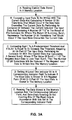
- a further Step E includes subsequently reading the data stored in the memory location and the corresponding indicator field, and selectively inverting or not inverting bits of the read data in accordance with bits set in the corresponding indicator field.
- Step B the energy required to write the data is given by E write * Sum + E Read * 8.
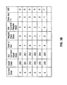
- FIG. 3B An example of the foregoing is shown in Figure 3B , where the example assumes that the current data is all zeroes and that the input data ranges in value from 250 to 255.
- one indicator bit is used with an eight bit word.
- the addition of one bit to indicate the change in parity is shown in Sum Xor +1, which represents the total number of bits which will be switched after the parity change.
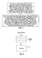
- Figure 4 is descriptive of a method to operate a memory device in accordance with the exemplary embodiments of this invention.
- the method includes at Block 4A, prior to overwriting a first unit of data at a location in a memory device with a second unit of data, determining if more energy is required to write the second unit of data than to write the second unit of data with at least one sub-unit thereof having bits that are inverted.
- the method further includes at Block 4B overwriting the first unit of data with a modified second unit of data with the at least one sub-unit thereof having bits that are inverted, in conjunction with writing at least one bit for indicating a location in the modified unit of data of the sub-unit of data having the inverted bits.
- FIGS. 3A and 4 may be viewed as method steps, and/or as operations that result from execution of computer program code stored in a computer-readable medium, and/or as a plurality of coupled logic circuit elements constructed to carry out the associated function(s). Note as well that some or all of the functionality of the memory control unit 16 shown in Figure 2 can be implemented by execution of computer program code stored in a computer-readable medium either alone or in combination with hardware circuitry.
- the indicator field can be stored in association with the corresponding data unit in the same memory 14, or it may be stored separately in another memory of the same or a different type that is addressed and read in synchronism with addressing and reading the (data) memory 14.
- the embodiments of this invention pertain as well to hard disk drives with patterned media.
- the exemplary embodiments of this invention are applicable to hard disk drives where long streams of data are stored in sectors.
- Current drives store approximately 512 bytes in a sector, and sectors are typically rewritten in blocks.
- future disk drive media are projected to be patterned in such a way that each bit resides in a separate discrete portion of the patterned media and can be written individually. By reducing the number of transitions 1 to 0, or vice versa, the write current can be reduced. In a lengthy data stream, the indicator bits can be applied.
- a sector is the basic unit of data storage on a hard disk.
- the term "sector" emanates from a mathematical term referring to a pie-shaped angular section of a circle, bounded on two sides by radii and the third by the perimeter of the circle.
- a hard disk is comprised of a group of predefined sectors that form a circle, and a given circle of predefined sectors is defined as a single track.
- a group of concentric circles (tracks) define a single surface of a disk's platter.
- Early hard disks had the same number of sectors per track location and typically the number of sectors in each track was fairly standard between models. When a hard disk is prepared with its default values, each sector is capable of storing 512 bytes of data. Current advances in hard disk drive technology have allowed the number of sectors per track, or SPT, to vary significantly.
- the exemplary embodiments of this invention can be used with advantage in both hard disks having a fixed number of sectors per track and in hard disks having a variable number of sectors per track.
- the exemplary embodiments of this invention can also be used to advantage in hard disk drives based on patterned media, wherein individual bits can be separately recorded (as opposed to recording at least an entire sector per write operation).
- the indicator field for a sector of data may be stored at the beginning or end of the sector, as desired.
- one or more sectors of a given track may be dedicated to storing the indicator fields for all of the sectors in the track.
- Other arrangements for storing the indicator information relative to the stored disk data can also be employed.
- RAID redundant array of inexpensive disks
- eight disk drives may be used for storing the data
- a ninth disk drive may be used for storing the indicator information, possibly in conjunction with error detection and correction information.
- RAID-type organizations are possible.
- a data buffer 30 such as a first in-first out (FIFO) buffer, can be provided for storing the client information before it is sent to the memory 14.
- FIFO first in-first out
- buffer 30 is described as storing data to be written to the same location in the memory 32, in other embodiments the buffer 30 may store enqueued commands to be applied to an arithmetic logic unit (ALU) of the processor 12.
- ALU arithmetic logic unit
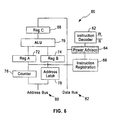
- FIG. 6 A simplified view of a portion of a data processor, such as a microprocessor 60, is shown in Fig 6 , which includes an ALU 70, registers A 72, B 74 and C 68, instruction decoder 62, instruction register 66, counter 76 and address latch 78. Both the counter 76 and the address latch 78 are connected to the address bus 80.
- the microprocessor 60 can execute a set of instructions, a subset of a typical instruction set is shown below.
- a program is a set of sequential instructions.
- the microprocessor 60 consumes energy to change the state of a bit within the circuitry of the ALU 70 or registers 68, 72, and 74. Methods which can reduce the number of bits which are changed can reduce the overall energy of the computation.
- One method to accomplish this is to include a power advisor 64 in the microprocessor 60 which examines the instructions and data bus 82 to minimize the number of transitions and therefore power.
- adding I and 255 results in changing 0000 0000 1111 1111 to 0000 0001 0000 0000 requiring 9 bits to transition from 0 to 1 or 1 to 0.
- This change may be preformed by the instruction set below: LOAD A 200 (load register A with the value in memory location 200 - 255 in this case) CON B I (load the number "1" into Register B) ADD (add the value in register A and the value in register B, store in Register C)
- the power advisor 64 monitors the instruction register 66, data bus 82 and registers 68, 72, and 74 may replace a certain instruction sequence of instructions with a reduced energy instruction set, for example using: CON C 256 (load the number "256" in Register C)
- This instruction eliminates or reduces processing which would occur in the ALU 70, and bit changes in registers A 72 and B 74, thus providing energy savings.
- Figure 7 is descriptive of a method to operate the power advisor 64 in accordance with the exemplary embodiments of this invention.
- the method includes: at Block 100, reading a first instruction set; at Block 110, reading a data bus; and at Block 120, reading register value(s) stored in at least one data register.
- the method further provides in Block 130, that the power advisor 64 analyzes the first instruction set, data bus, and register values for energy usage purposes.
- a second instruction set is determined to provide the same result as the first instruction set with a lower energy usage, it is used to replace the first instruction set.
- the resulting instruction set can then be applied to the ALU 70.
- the method to operate the power advisor 64 could be implemented solely on hardware, or in software, including firmware, or as a combination of hardware and software, including firmware.
- the exemplary embodiments of this invention can also be implemented through the use of a power hierarchy.
- power consumption is reduced, or is reduced further, by the use of the memory buffer 30, which preferably consumes less power per transition than the memory 14, to hold the data to be stored.
- the indicator bits may be placed directly in the data stream and decoded as such as the data is read out of the memory device.
- the data may be stored using two of the logic levels, while the indicator bit(s) are stored using a third logic level.
- the indicator fields may be considered to be distributed throughout the data that is stored and read back.
Landscapes
- Techniques For Improving Reliability Of Storages (AREA)
- Power Sources (AREA)
Applications Claiming Priority (2)
| Application Number | Priority Date | Filing Date | Title |
|---|---|---|---|
| US11/836,210 US7783846B2 (en) | 2007-08-09 | 2007-08-09 | Method, apparatus and computer program product providing energy reduction when storing data in a memory |
| PCT/EP2008/060330 WO2009019284A1 (en) | 2007-08-09 | 2008-08-06 | Providing energy reduction when storing data in a memory |
Publications (2)
| Publication Number | Publication Date |
|---|---|
| EP2176865A1 EP2176865A1 (en) | 2010-04-21 |
| EP2176865B1 true EP2176865B1 (en) | 2011-06-08 |
Family
ID=39926572
Family Applications (1)
| Application Number | Title | Priority Date | Filing Date |
|---|---|---|---|
| EP08786937A Active EP2176865B1 (en) | 2007-08-09 | 2008-08-06 | Providing energy reduction when storing data in a memory |
Country Status (7)
Families Citing this family (15)
| Publication number | Priority date | Publication date | Assignee | Title |
|---|---|---|---|---|
| US7925844B2 (en) * | 2007-11-29 | 2011-04-12 | Micron Technology, Inc. | Memory register encoding systems and methods |
| US8078795B2 (en) * | 2008-01-31 | 2011-12-13 | Dell Products L.P. | Methods and media for writing data to flash memory |
| US8769188B2 (en) * | 2009-11-18 | 2014-07-01 | Mediatek Inc. | Nonvolatile memory controller and method for writing data to nonvolatile memory |
| US8432729B2 (en) | 2010-04-13 | 2013-04-30 | Mosaid Technologies Incorporated | Phase-change memory with multiple polarity bits having enhanced endurance and error tolerance |
| US8555095B2 (en) * | 2010-07-26 | 2013-10-08 | Apple Inc. | Methods and systems for dynamically controlling operations in a non-volatile memory to limit power consumption |
| JP5942781B2 (ja) * | 2012-04-16 | 2016-06-29 | ソニー株式会社 | 記憶制御装置、メモリシステム、情報処理システム、および、記憶制御方法 |
| KR102049281B1 (ko) | 2012-10-23 | 2019-11-27 | 삼성전자주식회사 | 불휘발성 메모리 및 컨트롤러를 포함하는 메모리 시스템, 그리고 불휘발성 메모리에 데이터를 프로그램하는 프로그램 방법 |
| KR101419710B1 (ko) * | 2012-12-12 | 2014-08-13 | 어보브반도체 주식회사 | 플래시 메모리의 소모 전력 감소 방법 및 그 장치 |
| KR102211220B1 (ko) * | 2013-11-12 | 2021-02-03 | 에스케이하이닉스 주식회사 | 반도체 장치 및 이의 동작 방법 |
| CN103714294B (zh) * | 2013-12-24 | 2016-08-17 | 南京邮电大学 | 一种数据覆写方法 |
| US9740610B2 (en) * | 2014-12-24 | 2017-08-22 | Intel Corporation | Polarity based data transfer function for volatile memory |
| US9583207B2 (en) * | 2015-02-10 | 2017-02-28 | Sandisk Technologies Llc | Adaptive data shaping in nonvolatile memory |
| JP6694284B2 (ja) * | 2016-01-29 | 2020-05-13 | シナプティクス・ジャパン合同会社 | 画像データ伝送システム、送信回路及び受信回路 |
| CN107195321B (zh) * | 2017-05-15 | 2020-05-19 | 华中科技大学 | 一种交叉开关结构阻变式存储器性能优化方法及系统 |
| KR102683747B1 (ko) * | 2019-01-22 | 2024-07-11 | 에스케이하이닉스 주식회사 | 반도체 메모리 장치 |
Family Cites Families (9)
| Publication number | Priority date | Publication date | Assignee | Title |
|---|---|---|---|---|
| US5673224A (en) * | 1996-02-23 | 1997-09-30 | Micron Quantum Devices, Inc. | Segmented non-volatile memory array with multiple sources with improved word line control circuitry |
| US6292868B1 (en) | 1996-10-15 | 2001-09-18 | Micron Technology, Inc. | System and method for encoding data to reduce power and time required to write the encoded data to a flash memory |
| US5940332A (en) | 1997-11-13 | 1999-08-17 | Stmicroelectronics, Inc. | Programmed memory with improved speed and power consumption |
| US6633951B2 (en) | 2001-03-15 | 2003-10-14 | Intel Corporation | Method for reducing power consumption through dynamic memory storage inversion |
| JP2002366419A (ja) * | 2001-06-07 | 2002-12-20 | Mitsubishi Electric Corp | データ処理装置およびデータ処理方法 |
| US7549011B2 (en) * | 2001-08-30 | 2009-06-16 | Micron Technology, Inc. | Bit inversion in memory devices |
| JP4134637B2 (ja) * | 2002-08-27 | 2008-08-20 | 株式会社日立製作所 | 半導体装置 |
| JP4505195B2 (ja) * | 2003-04-01 | 2010-07-21 | エイティアイ テクノロジーズ インコーポレイテッド | メモリデバイスにおいてデータを反転させるための方法および装置 |
| JP2006053770A (ja) * | 2004-08-12 | 2006-02-23 | Seiko Epson Corp | データ処理装置、データ復元装置、データ処理方法及びデータ処理プログラム |
-
2007
- 2007-08-09 US US11/836,210 patent/US7783846B2/en active Active
-
2008
- 2008-08-06 EP EP08786937A patent/EP2176865B1/en active Active
- 2008-08-06 AT AT08786937T patent/ATE512441T1/de not_active IP Right Cessation
- 2008-08-06 WO PCT/EP2008/060330 patent/WO2009019284A1/en active Application Filing
- 2008-08-06 CN CN200880100678XA patent/CN101765885B/zh active Active
- 2008-08-06 JP JP2010519458A patent/JP5068367B2/ja not_active Expired - Fee Related
- 2008-08-06 KR KR1020107001944A patent/KR101071797B1/ko not_active Expired - Fee Related
Also Published As
| Publication number | Publication date |
|---|---|
| US20090043944A1 (en) | 2009-02-12 |
| EP2176865A1 (en) | 2010-04-21 |
| KR20100037121A (ko) | 2010-04-08 |
| JP2010536080A (ja) | 2010-11-25 |
| ATE512441T1 (de) | 2011-06-15 |
| CN101765885B (zh) | 2013-10-23 |
| JP5068367B2 (ja) | 2012-11-07 |
| US7783846B2 (en) | 2010-08-24 |
| WO2009019284A1 (en) | 2009-02-12 |
| KR101071797B1 (ko) | 2011-10-11 |
| CN101765885A (zh) | 2010-06-30 |
Similar Documents
| Publication | Publication Date | Title |
|---|---|---|
| EP2176865B1 (en) | Providing energy reduction when storing data in a memory | |
| TWI455136B (zh) | 用來進行資料整形之方法以及相關之記憶裝置及其控制器 | |
| US20090044032A1 (en) | Method, Apparatus and Computer Program Product Providing Instruction Monitoring for Reduction of Energy Usage | |
| US8719491B2 (en) | Encoding flash memory data with a randomizer using different seeds for different sectors | |
| US9983991B2 (en) | Data storage based on rank modulation in single-level flash memory | |
| US8458416B2 (en) | Systems and methods for selecting bit per cell density of a memory cell based on data typing | |
| WO2018192488A1 (zh) | 一种nand闪存设备的数据处理方法及装置 | |
| US8289768B2 (en) | Systems and methods for extended life multi-bit memory cells | |
| US7257668B2 (en) | Method and system for enhancing the endurance of memory cells | |
| KR20120052883A (ko) | 동시 판독 및 기록 메모리 동작을 수행하는 방법 및 장치 | |
| US8243536B2 (en) | Systems and methods for increasing bit density in a memory cell | |
| US20130326304A1 (en) | Error detection or correction of a portion of a codeword in a memory device | |
| US12019881B1 (en) | Reduced power consumption by SSD using host memory buffer | |
| CN113393884B (zh) | 组合qlc编程方法 | |
| US20110213995A1 (en) | Method, Apparatus And Computer Program Product Providing Instruction Monitoring For Reduction Of Energy Usage | |
| US9400748B2 (en) | System and method for data inversion in a storage resource | |
| TWI417719B (zh) | 提供能監測能源使用之減少以及在儲存資料於記憶體中時之能源減少的指令的方法、設備及電腦程式產品 | |
| KR20030051393A (ko) | 데이터 저장 장치 | |
| CN107622781B (zh) | 一种提升三层忆阻器写性能的编解码方法 | |
| US9864549B2 (en) | Systems and methods for high throughput multi-input compression | |
| CN100397529C (zh) | 省电的静态存储器控制电路 | |
| US20050013181A1 (en) | Assisted memory device with integrated cache | |
| CN105404473A (zh) | Nand flash存储器数据保持错误恢复方法 | |
| US11055231B2 (en) | Data storage devices and data processing methods of skipping editing of fields in H2F table when consecutive addresses are present in F2H table | |
| JPH10232789A (ja) | Eccパーシャルライト制御ユニット |
Legal Events
| Date | Code | Title | Description |
|---|---|---|---|
| PUAI | Public reference made under article 153(3) epc to a published international application that has entered the european phase |
Free format text: ORIGINAL CODE: 0009012 |
|
| 17P | Request for examination filed |
Effective date: 20100205 |
|
| AK | Designated contracting states |
Kind code of ref document: A1 Designated state(s): AT BE BG CH CY CZ DE DK EE ES FI FR GB GR HR HU IE IS IT LI LT LU LV MC MT NL NO PL PT RO SE SI SK TR |
|
| AX | Request for extension of the european patent |
Extension state: AL BA MK RS |
|
| GRAP | Despatch of communication of intention to grant a patent |
Free format text: ORIGINAL CODE: EPIDOSNIGR1 |
|
| DAX | Request for extension of the european patent (deleted) | ||
| GRAS | Grant fee paid |
Free format text: ORIGINAL CODE: EPIDOSNIGR3 |
|
| GRAA | (expected) grant |
Free format text: ORIGINAL CODE: 0009210 |
|
| AK | Designated contracting states |
Kind code of ref document: B1 Designated state(s): AT BE BG CH CY CZ DE DK EE ES FI FR GB GR HR HU IE IS IT LI LT LU LV MC MT NL NO PL PT RO SE SI SK TR |
|
| REG | Reference to a national code |
Ref country code: GB Ref legal event code: FG4D |
|
| REG | Reference to a national code |
Ref country code: CH Ref legal event code: NV Representative=s name: IBM RESEARCH GMBH ZURICH RESEARCH LABORATORY INTEL Ref country code: CH Ref legal event code: EP |
|
| REG | Reference to a national code |
Ref country code: IE Ref legal event code: FG4D |
|
| REG | Reference to a national code |
Ref country code: GB Ref legal event code: 746 Effective date: 20110624 |
|
| REG | Reference to a national code |
Ref country code: DE Ref legal event code: R096 Ref document number: 602008007467 Country of ref document: DE Effective date: 20110721 |
|
| REG | Reference to a national code |
Ref country code: DE Ref legal event code: R084 Ref document number: 602008007467 Country of ref document: DE |
|
| REG | Reference to a national code |
Ref country code: NL Ref legal event code: VDEP Effective date: 20110608 |
|
| PG25 | Lapsed in a contracting state [announced via postgrant information from national office to epo] |
Ref country code: HR Free format text: LAPSE BECAUSE OF FAILURE TO SUBMIT A TRANSLATION OF THE DESCRIPTION OR TO PAY THE FEE WITHIN THE PRESCRIBED TIME-LIMIT Effective date: 20110608 Ref country code: LT Free format text: LAPSE BECAUSE OF FAILURE TO SUBMIT A TRANSLATION OF THE DESCRIPTION OR TO PAY THE FEE WITHIN THE PRESCRIBED TIME-LIMIT Effective date: 20110608 Ref country code: SE Free format text: LAPSE BECAUSE OF FAILURE TO SUBMIT A TRANSLATION OF THE DESCRIPTION OR TO PAY THE FEE WITHIN THE PRESCRIBED TIME-LIMIT Effective date: 20110608 Ref country code: NO Free format text: LAPSE BECAUSE OF FAILURE TO SUBMIT A TRANSLATION OF THE DESCRIPTION OR TO PAY THE FEE WITHIN THE PRESCRIBED TIME-LIMIT Effective date: 20110908 |
|
| REG | Reference to a national code |
Ref country code: DE Ref legal event code: R084 Ref document number: 602008007467 Country of ref document: DE Effective date: 20110708 |
|
| PG25 | Lapsed in a contracting state [announced via postgrant information from national office to epo] |
Ref country code: SI Free format text: LAPSE BECAUSE OF FAILURE TO SUBMIT A TRANSLATION OF THE DESCRIPTION OR TO PAY THE FEE WITHIN THE PRESCRIBED TIME-LIMIT Effective date: 20110608 Ref country code: FI Free format text: LAPSE BECAUSE OF FAILURE TO SUBMIT A TRANSLATION OF THE DESCRIPTION OR TO PAY THE FEE WITHIN THE PRESCRIBED TIME-LIMIT Effective date: 20110608 Ref country code: ES Free format text: LAPSE BECAUSE OF FAILURE TO SUBMIT A TRANSLATION OF THE DESCRIPTION OR TO PAY THE FEE WITHIN THE PRESCRIBED TIME-LIMIT Effective date: 20110919 Ref country code: GR Free format text: LAPSE BECAUSE OF FAILURE TO SUBMIT A TRANSLATION OF THE DESCRIPTION OR TO PAY THE FEE WITHIN THE PRESCRIBED TIME-LIMIT Effective date: 20110909 Ref country code: LV Free format text: LAPSE BECAUSE OF FAILURE TO SUBMIT A TRANSLATION OF THE DESCRIPTION OR TO PAY THE FEE WITHIN THE PRESCRIBED TIME-LIMIT Effective date: 20110608 Ref country code: CY Free format text: LAPSE BECAUSE OF FAILURE TO SUBMIT A TRANSLATION OF THE DESCRIPTION OR TO PAY THE FEE WITHIN THE PRESCRIBED TIME-LIMIT Effective date: 20110608 Ref country code: AT Free format text: LAPSE BECAUSE OF FAILURE TO SUBMIT A TRANSLATION OF THE DESCRIPTION OR TO PAY THE FEE WITHIN THE PRESCRIBED TIME-LIMIT Effective date: 20110608 |
|
| PG25 | Lapsed in a contracting state [announced via postgrant information from national office to epo] |
Ref country code: BE Free format text: LAPSE BECAUSE OF FAILURE TO SUBMIT A TRANSLATION OF THE DESCRIPTION OR TO PAY THE FEE WITHIN THE PRESCRIBED TIME-LIMIT Effective date: 20110608 Ref country code: NL Free format text: LAPSE BECAUSE OF FAILURE TO SUBMIT A TRANSLATION OF THE DESCRIPTION OR TO PAY THE FEE WITHIN THE PRESCRIBED TIME-LIMIT Effective date: 20110608 Ref country code: MT Free format text: LAPSE BECAUSE OF FAILURE TO SUBMIT A TRANSLATION OF THE DESCRIPTION OR TO PAY THE FEE WITHIN THE PRESCRIBED TIME-LIMIT Effective date: 20110608 |
|
| PG25 | Lapsed in a contracting state [announced via postgrant information from national office to epo] |
Ref country code: PT Free format text: LAPSE BECAUSE OF FAILURE TO SUBMIT A TRANSLATION OF THE DESCRIPTION OR TO PAY THE FEE WITHIN THE PRESCRIBED TIME-LIMIT Effective date: 20111010 Ref country code: CZ Free format text: LAPSE BECAUSE OF FAILURE TO SUBMIT A TRANSLATION OF THE DESCRIPTION OR TO PAY THE FEE WITHIN THE PRESCRIBED TIME-LIMIT Effective date: 20110608 Ref country code: EE Free format text: LAPSE BECAUSE OF FAILURE TO SUBMIT A TRANSLATION OF THE DESCRIPTION OR TO PAY THE FEE WITHIN THE PRESCRIBED TIME-LIMIT Effective date: 20110608 Ref country code: IS Free format text: LAPSE BECAUSE OF FAILURE TO SUBMIT A TRANSLATION OF THE DESCRIPTION OR TO PAY THE FEE WITHIN THE PRESCRIBED TIME-LIMIT Effective date: 20111008 |
|
| PG25 | Lapsed in a contracting state [announced via postgrant information from national office to epo] |
Ref country code: SK Free format text: LAPSE BECAUSE OF FAILURE TO SUBMIT A TRANSLATION OF THE DESCRIPTION OR TO PAY THE FEE WITHIN THE PRESCRIBED TIME-LIMIT Effective date: 20110608 Ref country code: RO Free format text: LAPSE BECAUSE OF FAILURE TO SUBMIT A TRANSLATION OF THE DESCRIPTION OR TO PAY THE FEE WITHIN THE PRESCRIBED TIME-LIMIT Effective date: 20110608 Ref country code: PL Free format text: LAPSE BECAUSE OF FAILURE TO SUBMIT A TRANSLATION OF THE DESCRIPTION OR TO PAY THE FEE WITHIN THE PRESCRIBED TIME-LIMIT Effective date: 20110608 |
|
| PG25 | Lapsed in a contracting state [announced via postgrant information from national office to epo] |
Ref country code: MC Free format text: LAPSE BECAUSE OF NON-PAYMENT OF DUE FEES Effective date: 20110831 |
|
| PLBE | No opposition filed within time limit |
Free format text: ORIGINAL CODE: 0009261 |
|
| STAA | Information on the status of an ep patent application or granted ep patent |
Free format text: STATUS: NO OPPOSITION FILED WITHIN TIME LIMIT |
|
| 26N | No opposition filed |
Effective date: 20120309 |
|
| REG | Reference to a national code |
Ref country code: IE Ref legal event code: MM4A |
|
| PG25 | Lapsed in a contracting state [announced via postgrant information from national office to epo] |
Ref country code: IT Free format text: LAPSE BECAUSE OF FAILURE TO SUBMIT A TRANSLATION OF THE DESCRIPTION OR TO PAY THE FEE WITHIN THE PRESCRIBED TIME-LIMIT Effective date: 20110608 |
|
| PG25 | Lapsed in a contracting state [announced via postgrant information from national office to epo] |
Ref country code: DK Free format text: LAPSE BECAUSE OF FAILURE TO SUBMIT A TRANSLATION OF THE DESCRIPTION OR TO PAY THE FEE WITHIN THE PRESCRIBED TIME-LIMIT Effective date: 20110608 |
|
| REG | Reference to a national code |
Ref country code: DE Ref legal event code: R097 Ref document number: 602008007467 Country of ref document: DE Effective date: 20120309 |
|
| PG25 | Lapsed in a contracting state [announced via postgrant information from national office to epo] |
Ref country code: IE Free format text: LAPSE BECAUSE OF NON-PAYMENT OF DUE FEES Effective date: 20110806 |
|
| PGFP | Annual fee paid to national office [announced via postgrant information from national office to epo] |
Ref country code: FR Payment date: 20120830 Year of fee payment: 5 |
|
| REG | Reference to a national code |
Ref country code: CH Ref legal event code: PL |
|
| PG25 | Lapsed in a contracting state [announced via postgrant information from national office to epo] |
Ref country code: CH Free format text: LAPSE BECAUSE OF NON-PAYMENT OF DUE FEES Effective date: 20120831 Ref country code: LI Free format text: LAPSE BECAUSE OF NON-PAYMENT OF DUE FEES Effective date: 20120831 |
|
| PG25 | Lapsed in a contracting state [announced via postgrant information from national office to epo] |
Ref country code: LU Free format text: LAPSE BECAUSE OF NON-PAYMENT OF DUE FEES Effective date: 20110806 |
|
| PG25 | Lapsed in a contracting state [announced via postgrant information from national office to epo] |
Ref country code: BG Free format text: LAPSE BECAUSE OF FAILURE TO SUBMIT A TRANSLATION OF THE DESCRIPTION OR TO PAY THE FEE WITHIN THE PRESCRIBED TIME-LIMIT Effective date: 20110908 |
|
| PG25 | Lapsed in a contracting state [announced via postgrant information from national office to epo] |
Ref country code: TR Free format text: LAPSE BECAUSE OF FAILURE TO SUBMIT A TRANSLATION OF THE DESCRIPTION OR TO PAY THE FEE WITHIN THE PRESCRIBED TIME-LIMIT Effective date: 20110608 |
|
| PG25 | Lapsed in a contracting state [announced via postgrant information from national office to epo] |
Ref country code: HU Free format text: LAPSE BECAUSE OF FAILURE TO SUBMIT A TRANSLATION OF THE DESCRIPTION OR TO PAY THE FEE WITHIN THE PRESCRIBED TIME-LIMIT Effective date: 20110608 |
|
| REG | Reference to a national code |
Ref country code: FR Ref legal event code: ST Effective date: 20140430 |
|
| PG25 | Lapsed in a contracting state [announced via postgrant information from national office to epo] |
Ref country code: FR Free format text: LAPSE BECAUSE OF NON-PAYMENT OF DUE FEES Effective date: 20130902 |
|
| REG | Reference to a national code |
Ref country code: DE Ref legal event code: R082 Ref document number: 602008007467 Country of ref document: DE Representative=s name: KUISMA, SIRPA, FI |
|
| P01 | Opt-out of the competence of the unified patent court (upc) registered |
Effective date: 20230423 |
|
| PGFP | Annual fee paid to national office [announced via postgrant information from national office to epo] |
Ref country code: DE Payment date: 20240808 Year of fee payment: 17 |
|
| PGFP | Annual fee paid to national office [announced via postgrant information from national office to epo] |
Ref country code: GB Payment date: 20240828 Year of fee payment: 17 |