EP2176633B1 - Procédé d'estimation d'au moins une déformation du front d'onde d'un système optique ou d'un objet observé par le système optique et dispositif associé - Google Patents
Procédé d'estimation d'au moins une déformation du front d'onde d'un système optique ou d'un objet observé par le système optique et dispositif associé Download PDFInfo
- Publication number
- EP2176633B1 EP2176633B1 EP08775271.3A EP08775271A EP2176633B1 EP 2176633 B1 EP2176633 B1 EP 2176633B1 EP 08775271 A EP08775271 A EP 08775271A EP 2176633 B1 EP2176633 B1 EP 2176633B1
- Authority
- EP
- European Patent Office
- Prior art keywords
- diversity
- deformation
- image
- pupil
- plane
- Prior art date
- Legal status (The legal status is an assumption and is not a legal conclusion. Google has not performed a legal analysis and makes no representation as to the accuracy of the status listed.)
- Active
Links
Images

Classifications
-
- G—PHYSICS
- G01—MEASURING; TESTING
- G01M—TESTING STATIC OR DYNAMIC BALANCE OF MACHINES OR STRUCTURES; TESTING OF STRUCTURES OR APPARATUS, NOT OTHERWISE PROVIDED FOR
- G01M11/00—Testing of optical apparatus; Testing structures by optical methods not otherwise provided for
- G01M11/02—Testing optical properties
- G01M11/0242—Testing optical properties by measuring geometrical properties or aberrations
- G01M11/0257—Testing optical properties by measuring geometrical properties or aberrations by analyzing the image formed by the object to be tested
Definitions
- the present invention relates to a method and a device for estimating at least one distortion of the wavefront of an optical system or an object observed by the optical system.
- the invention is particularly applicable in the field of high resolution imaging and beam shaping.
- the deformations can be introduced by an optical system and / or by the light propagation medium.
- the invention allows the estimation (restoration) of the object observed.
- the quality of the images obtained by an optical instrument is often degraded because of the presence of aberrations or other perturbations in the path of the wave coming from the observed object.
- phase deformations present in the pupil of the instrument, attenuate the transfer function.
- ASO Wave Surface Analyzers
- ASO information can be used to restore (estimate) the observed object.
- focal plane techniques appear as seductive solutions.
- the focal plane methods make it possible to measure the deformations of the wavefront as well as the combination of all the sub-pupils in a single frame, with a simple opto-mechanical design.
- a focal plane device is disclosed in the document. US2004 / 0052426 . If the entrance pupil of the instrument is known, the so-called “ Phase Retrieval " technique makes it possible to estimate the aberrations that are most compatible with the known constraints in the pupil plane and in the focal plane, and with the only data of the focal image of a source point. However, this technique must be used for instruments with non-centro-symmetric pupillary configurations in order to estimate deformations (or "aberrant phase") without ambiguity of sign.
- the estimation of the aberrant phase is then based on an approach that consists in choosing the aberrations that minimize a distance criterion to the images.
- phase diversity method is commonly applied to extended object phase measurement.
- N is the number of images acquired by diversity
- 2N Fourier transforms are at least performed at each iteration, knowing that fifty or so iterations may be necessary in practice.
- the aim of the invention is to estimate deformations of a wavefront of an observation system or of the object observed by the system from one or more images taken in the vicinity of the focal plane of a radar system. observation by means of a non-iterative but purely analytical process.
- the invention relates to a method for estimating at least one wavefront deformation of an observation system or an object observed by the system.
- the method of the invention is characterized in that, in the vicinity of the focal plane of the observation system, at least one diversity image is acquired in at least one diversity plane, the diversity image comprising a deformation of known diversity; and in that in every plane of diversity; determining an image model based on at least: a decomposition of the pupillary transmission of the physical pupil of the system into a plurality of sub-pupils; a decomposition on each sub-pupil of the desired strain in the form of at least one known deformation weighted by coefficients to be determined; a determination of the optical transfer function of the system by autocorrelation of the pupillary transmission of its pupil; linearization, in said optical transfer function, of each of the terms of the autocorrelation as a function of the coefficients of the desired deformation, the linearization being carried out in the vicinity of the known diversity deformation; the observed object and noise; and in that from the determined image model (s) and the acquired image (s), the desired deformation (s) is estimated or the object being observed.
- the image model is also a function of the object observed by the system and the linearized transfer function.
- the method of the invention applies to an extended object and does not require any iteration thereby minimizing the computation time.
- the method of the invention is based on the linearization of the transfer function of the observation system. Such linearization makes it possible to obtain an estimate of the deformations or the object observed.
- the transfer function of the observation system is linearized in each diversity plane and is at least a function of the desired deformation (s) and the known diversity deformation associated with each diversity plane.
- the observation system is an optical observation system and the transfer function of the system is the optical transfer function, acoustic imaging.
- the invention relates to a device for estimating at least one deformation of the wavefront of an observation system or an object observed by the system.
- the device of the invention is characterized in that it comprises means for acquiring, in the vicinity of the focal plane of the observation system, at least one diversity image in at least one diversity plane, the diversity image comprising a known diversity deformation; and in that in each diversity plane the device comprises: means for determining an image model based on at least: a decomposition of the physical pupil of the system into a plurality of sub-pupils; a decomposition on each sub-pupil of the desired strain in the form of at least one known deformation weighted by coefficients to be determined; a determination of the transfer function of the system by autocorrelation of its pupil; the linearization of each of the autocorrelation terms as a function of the coefficients of the desired deformation, the linearization being carried out in the vicinity of the known diversity deformation; the observed object and noise; and in that from the determined image model (s) and the acquired image (s), the desired deformation (s) is estimated or the object being observed.
- the device is adapted to implement a process that does not require iteration, it respects strong real-time constraints and integrates perfectly into embedded systems.
- the device of the invention can be used in closed loop in conjunction with correction means, for the real time correction of the wavefront deformations of an optical system and / or to estimate further the object observed by the observation system.
- the invention relates to an embedded system comprising means for implementing the method according to the first aspect of the invention.
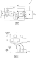
- the figure 1 illustrates a device for estimating the wavefront deformations of an optical system or an object observed by an optical system.
- Incidental and / or positioning deformations of an optical system 20 are estimated by an analytical method implemented in computing means 30 of the device 1.
- the aberrations thus estimated 40 can then optionally be re-directed to the optical system 20 to be corrected.
- the analytical method also makes it possible to restore the object 50.
- observation instrument may be monolithic or with a segmented pupil 21.
- the device may be downstream of a recombination system of the beams 23.
- a diversity image is an image in which a known diversity deformation is added.
- the aberrant phase on the imaging sensor may be different from that seen by the sensor, denoted ⁇ S.
- the measurement method does not require the introduction of a reference source; the images are therefore directly derived from the observed object.
- the wavefront aberration measurement is based on the use of the acquired images which contain the aberrant phase ⁇ S as well as the diversity deformations.
- the aberrations thus estimated 40 may then possibly be corrected by correction means 22, for example a deformable mirror.
- the acquired images are modeled as a function of the sought-after deformations, of the object, as well as of all the relevant physical parameters, such as the introduced phase modulation and the optical detection characteristics of the optical system.
- a plan of diversity can be an extra-focal plane, the deformation of known diversity is then in this case a defocusing.
- the deformation of diversity may be any.
- the figure 2 illustrates an embodiment for estimating the observed object.
- At least two diversity images are generated 25, either on separate sensors or on the same sensor. In the latter case, the acquisition of the images can be done sequentially.
- the figure 2 illustrates a chronogram of image acquisition sequentially.
- the block 25 involves in the optical train any system for introducing a diversity deformation.
- a system can be a membrane, a bimorph mirror, an electro-optical system, etc.
- the method for estimating the observed object is implemented by means of a dedicated printed circuit which takes into account the parameters of the optical system (shape of the pupil, observation wavelength, etc.) and which allows to estimate the observed object 50 on all the frames of two images (see figure 2 ).
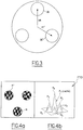
- p be the transmission of the pupillary configuration, composed of N T sub-pupils placed at the position u n and each having a phase denoted ⁇ n .
- the pupil transmission is perfect and is worth 1.
- the shape of the pupil or sub-pupils can be arbitrary, for example circular, hexagonal or square, etc.
- Equations (1) and (2) allow to decompose the pupil and the phase in a base known in advance. It remains to find the coefficients kn of this double decomposition.
- N a 18
- N T is the number of sub-pupils
- the optical transfer function has a central peak, sum of N T individual peaks plus N T (N T -1) satellite peaks.
- N T the optical transfer function
- the measurement principle is based on the fact that one will look for the deformations and / or the object producing a model closest to the images acquired, which amounts to minimizing a distance criterion J between the reconstructed model and the data obtained. in each plane.
- the criterion is, for example, quadratic.
- equation (8) is non-linear in phase but quadratic in object.
- equation (8) is non-linear in phase but quadratic in object.
- o ⁇ m ⁇ S 0 ⁇ and ⁇ ⁇ 2 S 0 ⁇ are terms related to a possible regularization on the object (if there is no regularization, these terms are equal to zero); in addition ⁇ ⁇ 2 S 0 ⁇ is the ratio of the spectral power densities of the noise ( ⁇ 2 ) and the object (S 0 ( ⁇ )) weighted
- the measurement method uses an analytical algorithm developed under the assumption of weak phases ⁇ S on the ASO.
- this algorithm is used around an operating point, that is to say around ⁇ S - ⁇ C , or for example with aberrant phase ⁇ low (operating point close to zero).
- N i be the number of pixels in the image, typically 128 ⁇ 128 or 256 ⁇ 256.
- the digitized transfer function that is to say defined in a space compatible with that of the recorded image, thus pixelated, is defined on N f frequencies, with N f ⁇ N i .
- the matrix A is thus of size N f ⁇ N a and B is of size N f ⁇ 1.
- R AT H B or refers to the real party operator.
- the inversion of the matrix A H A is not dimensioning since of size N a ⁇ N a and that N has ⁇ N f ; the calculation time is then reduced to the time required to perform the N d Fourier transforms.
- the figure 5 illustrates the estimator 30 (as noted on the figure 1 ).
- the estimator 30 (as noted on the figure 1 ).
- two diversity images noted 26 and 27 an embodiment, that allowing the estimation of the pistons and higher modes (first-order development as a function of a, therefore).
- the aberrations can be found by applying a reconstructor R to an error signal derived from the diversity images; R is then pre-defined and calculated once and for all for all the physical parameters defining the system; it should be noted that in this case, the object initially taken into account is a medium object, requiring a priori knowledge of the scenes that will be observed.
- this object can be adjusted as the loop stabilizes.
- the reconstructor is determined in advance: the models that will be associated with the images, of size N a ⁇ N f , are calculated under the assumption of weak phase ⁇ S on the ASO by combination 31 of the functions transfer 31.1 and 31.2 obtained in the two diversity plans. We then obtain two matrices 31.3 and 31.4.
- the sub-reconstructor 31.3 is multiplied matricially to the Fourier transform of the image 27; the same operation is performed between the matrix 31.4 and the image 26.
- the two resulting matrices 32 and 33 are then subtracted in order to obtain the function x, which used to infer the desired 40 to 34 aberrations.
- the images can also be used to adjust the object used in the reconstructor (hence the dots shown on the figure 6 ).
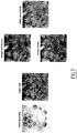
- the figure 7 illustrates the estimation of the object observed by an optical system consisting of eighteen sub-pupils.
- This pupil (composed of sub-pupils) is very close to that of a monolithic telescope, which shows that the current device could be applied to such a telescope with hexagonal sub-pupils for example.
- Two images are simulated from this phase hypothesis on the instrument and a reference object: an image in the focal plane and an image in a defocused plane of 1 rad rms, with a good signal-to-noise ratio.
- the object is then reconstructed by deconvolving the measured image in the focal plane, using the estimated phase.
- the figure 7 shows that the object thus estimated by simple digital processing is very close to the observed object, in particular that the details (cars on the parking for example) are much sharper than on the focal image without treatment.
Landscapes
- Physics & Mathematics (AREA)
- Geometry (AREA)
- Chemical & Material Sciences (AREA)
- Analytical Chemistry (AREA)
- General Physics & Mathematics (AREA)
- Testing Of Optical Devices Or Fibers (AREA)
- Microscoopes, Condenser (AREA)
Priority Applications (1)
| Application Number | Priority Date | Filing Date | Title |
|---|---|---|---|
| PL08775271T PL2176633T3 (pl) | 2007-07-19 | 2008-07-21 | Sposób oszacowania co najmniej jednego zniekształcenia czoła fali układu optycznego lub obiektu obserwowanego przez układ optyczny i odpowiednie urządzenie |
Applications Claiming Priority (2)
| Application Number | Priority Date | Filing Date | Title |
|---|---|---|---|
| FR0756615A FR2919052B1 (fr) | 2007-07-19 | 2007-07-19 | Procede d'estimation d'au moins une deformation du front d'onde d'un systeme optique ou d'un objet observe par le systeme optique et dispositif associe |
| PCT/EP2008/059548 WO2009010593A2 (fr) | 2007-07-19 | 2008-07-21 | Procede d'estimation d'au moins une deformation du front d'onde d'un systeme optique ou d'un objet observe par le systeme optique et dispositif associe |
Publications (2)
| Publication Number | Publication Date |
|---|---|
| EP2176633A2 EP2176633A2 (fr) | 2010-04-21 |
| EP2176633B1 true EP2176633B1 (fr) | 2017-08-30 |
Family
ID=39400363
Family Applications (1)
| Application Number | Title | Priority Date | Filing Date |
|---|---|---|---|
| EP08775271.3A Active EP2176633B1 (fr) | 2007-07-19 | 2008-07-21 | Procédé d'estimation d'au moins une déformation du front d'onde d'un système optique ou d'un objet observé par le système optique et dispositif associé |
Country Status (8)
| Country | Link |
|---|---|
| US (1) | US8351738B2 (enExample) |
| EP (1) | EP2176633B1 (enExample) |
| JP (1) | JP5554234B2 (enExample) |
| CN (1) | CN101779112B (enExample) |
| ES (1) | ES2649760T3 (enExample) |
| FR (1) | FR2919052B1 (enExample) |
| PL (1) | PL2176633T3 (enExample) |
| WO (1) | WO2009010593A2 (enExample) |
Families Citing this family (3)
| Publication number | Priority date | Publication date | Assignee | Title |
|---|---|---|---|---|
| FR2974899B1 (fr) | 2011-05-05 | 2013-05-17 | Thales Sa | Telescope multispectral a balayage comportant des moyens d'analyses de front d'onde |
| FR2995677B1 (fr) | 2012-09-14 | 2014-08-29 | Thales Sa | Instrument d'optique a analyseur de front d'onde |
| CN114279360B (zh) * | 2021-12-27 | 2023-08-11 | 天津大学 | 基于远心成像系统的多目相位偏折测量方法及装置 |
Family Cites Families (13)
| Publication number | Priority date | Publication date | Assignee | Title |
|---|---|---|---|---|
| US4309602A (en) * | 1979-11-01 | 1982-01-05 | Eikonix Corportation | Wavefront sensing by phase retrieval |
| JPS58205834A (ja) * | 1982-05-25 | 1983-11-30 | Canon Inc | 収差測定方法 |
| US5471346A (en) * | 1992-03-13 | 1995-11-28 | Lockheed Missiles & Space Co., Inc. | Casegrain telescope with spherical mirror surfaces |
| US5412200A (en) * | 1993-03-01 | 1995-05-02 | Rhoads; Geoffrey B. | Wide field distortion-compensating imaging system and methods |
| US5610707A (en) * | 1995-07-07 | 1997-03-11 | Lockheed Missiles & Space Co., Inc. | Wavefront sensor for a staring imager |
| US5905591A (en) * | 1997-02-18 | 1999-05-18 | Lockheed Martin Corporation | Multi-aperture imaging system |
| EP1072922B1 (de) * | 1999-02-13 | 2003-07-23 | Leica Geosystems AG | Teleskop mit einer Korrektur von optischen Wellenfrontfehlern |
| US20040052426A1 (en) * | 2002-09-12 | 2004-03-18 | Lockheed Martin Corporation | Non-iterative method and system for phase retrieval |
| US6787747B2 (en) * | 2002-09-24 | 2004-09-07 | Lockheed Martin Corporation | Fast phase diversity wavefront correction using a neural network |
| CN1768346B (zh) * | 2003-03-31 | 2010-11-17 | Cdm光学有限公司 | 用于最小化成像系统中的光程差效应的系统和方法 |
| GB0314444D0 (en) * | 2003-06-20 | 2003-07-23 | Univ Heriot Watt | Novel wavefront sensor |
| US7928351B1 (en) * | 2004-05-10 | 2011-04-19 | Lockheed Martin Corporation | Near field diversity method for estimation and correction of aberrations |
| US20050259269A1 (en) * | 2004-05-19 | 2005-11-24 | Asml Holding N.V. | Shearing interferometer with dynamic pupil fill |
-
2007
- 2007-07-19 FR FR0756615A patent/FR2919052B1/fr active Active
-
2008
- 2008-07-21 JP JP2010516526A patent/JP5554234B2/ja active Active
- 2008-07-21 CN CN200880025262.6A patent/CN101779112B/zh active Active
- 2008-07-21 PL PL08775271T patent/PL2176633T3/pl unknown
- 2008-07-21 ES ES08775271.3T patent/ES2649760T3/es active Active
- 2008-07-21 WO PCT/EP2008/059548 patent/WO2009010593A2/fr not_active Ceased
- 2008-07-21 EP EP08775271.3A patent/EP2176633B1/fr active Active
- 2008-07-21 US US12/669,524 patent/US8351738B2/en active Active
Non-Patent Citations (1)
| Title |
|---|
| None * |
Also Published As
| Publication number | Publication date |
|---|---|
| CN101779112B (zh) | 2016-08-03 |
| FR2919052A1 (fr) | 2009-01-23 |
| JP5554234B2 (ja) | 2014-07-23 |
| CN101779112A (zh) | 2010-07-14 |
| JP2010533888A (ja) | 2010-10-28 |
| US20100189377A1 (en) | 2010-07-29 |
| PL2176633T3 (pl) | 2018-02-28 |
| US8351738B2 (en) | 2013-01-08 |
| WO2009010593A3 (fr) | 2009-04-16 |
| FR2919052B1 (fr) | 2009-11-06 |
| WO2009010593A2 (fr) | 2009-01-22 |
| EP2176633A2 (fr) | 2010-04-21 |
| ES2649760T3 (es) | 2018-01-15 |
Similar Documents
| Publication | Publication Date | Title |
|---|---|---|
| EP3824269B1 (fr) | Procédé et systèmes de caracterisation optique non invasive d'un milieu héterogène | |
| Chambouleyron et al. | Focal-plane-assisted pyramid wavefront sensor: Enabling frame-by-frame optical gain tracking | |
| EP3290891B1 (fr) | Procédé et dispositif de caractérisation des aberrations d'un système optique | |
| EP2947433A1 (fr) | Système et procédé d'acquisition d'images hyperspectrales | |
| EP1012549B1 (fr) | Procede et dispositif d'analyse optique de surface d'onde | |
| US7646327B1 (en) | Synthetic aperture radar motion estimation method | |
| Voelz et al. | Image synthesis from nonimaged laser-speckle patterns: comparison of theory, computer simulation, and laboratory results | |
| EP2176633B1 (fr) | Procédé d'estimation d'au moins une déformation du front d'onde d'un système optique ou d'un objet observé par le système optique et dispositif associé | |
| EP2980529B1 (fr) | Procede d'estimation de la distance d'un objet a un systeme d'imagerie | |
| EP2078184B1 (fr) | Procédé de correction d'un analyseur de front d'onde, et analyseur implémentant ce procédé | |
| FR2881520A1 (fr) | Obtention d'une image de phase a partir d'une image d'intensite | |
| EP3785083B1 (fr) | Procede de traitement d'un hologramme, dispositif, systeme de restitution holographique et programme d'ordinateur associes | |
| FR2947049B1 (fr) | Systeme et procede d'interferometrie statique | |
| EP2747421B1 (fr) | Procede et dispositif de correction de reponse spatiale pour spectrometres a transformee de fourier imageurs | |
| Kirkove et al. | ADMM-inspired image reconstruction for terahertz off-axis digital holography | |
| Choi et al. | Poisson wavefront imaging in photon-starved scenarios | |
| Li et al. | The design of a method for recovering degraded images of atmospheric turbulence based on deep learning | |
| EP1990618B1 (fr) | Procédé et dispositif de mesure d'au moins une déformation d'une surface d'onde | |
| EP1078321A1 (fr) | Procede pour reconstruire une surface avec mise en oeuvre d'une prediction lineaire et applications de ce procede | |
| EP2884456A1 (fr) | Procédé de réstitution du mouvement haute fréquence de la ligne de visée d'un imageur | |
| Jurling et al. | A Fast Approximation Method for Broadband Phase Retrieval | |
| Luna et al. | Phase diverse wavefront estimation and image restoration with a magnification change between imaging channels | |
| Jurling et al. | Fast Approximate Broadband Phase Retrieval for Segmented Systems | |
| Hope et al. | High-resolution imaging through strong turbulence | |
| FR3079651A1 (fr) | Procede et systeme d'etalonnage d'au moins un parametre d'un dispositif d'acquisition d'images |
Legal Events
| Date | Code | Title | Description |
|---|---|---|---|
| PUAI | Public reference made under article 153(3) epc to a published international application that has entered the european phase |
Free format text: ORIGINAL CODE: 0009012 |
|
| 17P | Request for examination filed |
Effective date: 20100219 |
|
| AK | Designated contracting states |
Kind code of ref document: A2 Designated state(s): AT BE BG CH CY CZ DE DK EE ES FI FR GB GR HR HU IE IS IT LI LT LU LV MC MT NL NO PL PT RO SE SI SK TR |
|
| AX | Request for extension of the european patent |
Extension state: AL BA MK RS |
|
| DAX | Request for extension of the european patent (deleted) | ||
| GRAP | Despatch of communication of intention to grant a patent |
Free format text: ORIGINAL CODE: EPIDOSNIGR1 |
|
| STAA | Information on the status of an ep patent application or granted ep patent |
Free format text: STATUS: GRANT OF PATENT IS INTENDED |
|
| INTG | Intention to grant announced |
Effective date: 20170220 |
|
| GRAS | Grant fee paid |
Free format text: ORIGINAL CODE: EPIDOSNIGR3 |
|
| RAP1 | Party data changed (applicant data changed or rights of an application transferred) |
Owner name: OFFICE NATIONAL D'ETUDES ET DE RECHERCHES AEROSPAT |
|
| GRAA | (expected) grant |
Free format text: ORIGINAL CODE: 0009210 |
|
| STAA | Information on the status of an ep patent application or granted ep patent |
Free format text: STATUS: THE PATENT HAS BEEN GRANTED |
|
| AK | Designated contracting states |
Kind code of ref document: B1 Designated state(s): AT BE BG CH CY CZ DE DK EE ES FI FR GB GR HR HU IE IS IT LI LT LU LV MC MT NL NO PL PT RO SE SI SK TR |
|
| REG | Reference to a national code |
Ref country code: GB Ref legal event code: FG4D Free format text: NOT ENGLISH |
|
| REG | Reference to a national code |
Ref country code: CH Ref legal event code: EP |
|
| REG | Reference to a national code |
Ref country code: AT Ref legal event code: REF Ref document number: 924025 Country of ref document: AT Kind code of ref document: T Effective date: 20170915 |
|
| REG | Reference to a national code |
Ref country code: IE Ref legal event code: FG4D Free format text: LANGUAGE OF EP DOCUMENT: FRENCH |
|
| REG | Reference to a national code |
Ref country code: DE Ref legal event code: R096 Ref document number: 602008051910 Country of ref document: DE |
|
| REG | Reference to a national code |
Ref country code: NL Ref legal event code: FP |
|
| REG | Reference to a national code |
Ref country code: LT Ref legal event code: MG4D |
|
| REG | Reference to a national code |
Ref country code: ES Ref legal event code: FG2A Ref document number: 2649760 Country of ref document: ES Kind code of ref document: T3 Effective date: 20180115 Ref country code: AT Ref legal event code: MK05 Ref document number: 924025 Country of ref document: AT Kind code of ref document: T Effective date: 20170830 |
|
| PG25 | Lapsed in a contracting state [announced via postgrant information from national office to epo] |
Ref country code: NO Free format text: LAPSE BECAUSE OF FAILURE TO SUBMIT A TRANSLATION OF THE DESCRIPTION OR TO PAY THE FEE WITHIN THE PRESCRIBED TIME-LIMIT Effective date: 20171130 Ref country code: FI Free format text: LAPSE BECAUSE OF FAILURE TO SUBMIT A TRANSLATION OF THE DESCRIPTION OR TO PAY THE FEE WITHIN THE PRESCRIBED TIME-LIMIT Effective date: 20170830 Ref country code: SE Free format text: LAPSE BECAUSE OF FAILURE TO SUBMIT A TRANSLATION OF THE DESCRIPTION OR TO PAY THE FEE WITHIN THE PRESCRIBED TIME-LIMIT Effective date: 20170830 Ref country code: LT Free format text: LAPSE BECAUSE OF FAILURE TO SUBMIT A TRANSLATION OF THE DESCRIPTION OR TO PAY THE FEE WITHIN THE PRESCRIBED TIME-LIMIT Effective date: 20170830 Ref country code: HR Free format text: LAPSE BECAUSE OF FAILURE TO SUBMIT A TRANSLATION OF THE DESCRIPTION OR TO PAY THE FEE WITHIN THE PRESCRIBED TIME-LIMIT Effective date: 20170830 Ref country code: AT Free format text: LAPSE BECAUSE OF FAILURE TO SUBMIT A TRANSLATION OF THE DESCRIPTION OR TO PAY THE FEE WITHIN THE PRESCRIBED TIME-LIMIT Effective date: 20170830 |
|
| PG25 | Lapsed in a contracting state [announced via postgrant information from national office to epo] |
Ref country code: LV Free format text: LAPSE BECAUSE OF FAILURE TO SUBMIT A TRANSLATION OF THE DESCRIPTION OR TO PAY THE FEE WITHIN THE PRESCRIBED TIME-LIMIT Effective date: 20170830 Ref country code: BG Free format text: LAPSE BECAUSE OF FAILURE TO SUBMIT A TRANSLATION OF THE DESCRIPTION OR TO PAY THE FEE WITHIN THE PRESCRIBED TIME-LIMIT Effective date: 20171130 Ref country code: GR Free format text: LAPSE BECAUSE OF FAILURE TO SUBMIT A TRANSLATION OF THE DESCRIPTION OR TO PAY THE FEE WITHIN THE PRESCRIBED TIME-LIMIT Effective date: 20171201 Ref country code: IS Free format text: LAPSE BECAUSE OF FAILURE TO SUBMIT A TRANSLATION OF THE DESCRIPTION OR TO PAY THE FEE WITHIN THE PRESCRIBED TIME-LIMIT Effective date: 20171230 |
|
| PG25 | Lapsed in a contracting state [announced via postgrant information from national office to epo] |
Ref country code: DK Free format text: LAPSE BECAUSE OF FAILURE TO SUBMIT A TRANSLATION OF THE DESCRIPTION OR TO PAY THE FEE WITHIN THE PRESCRIBED TIME-LIMIT Effective date: 20170830 Ref country code: CZ Free format text: LAPSE BECAUSE OF FAILURE TO SUBMIT A TRANSLATION OF THE DESCRIPTION OR TO PAY THE FEE WITHIN THE PRESCRIBED TIME-LIMIT Effective date: 20170830 Ref country code: RO Free format text: LAPSE BECAUSE OF FAILURE TO SUBMIT A TRANSLATION OF THE DESCRIPTION OR TO PAY THE FEE WITHIN THE PRESCRIBED TIME-LIMIT Effective date: 20170830 |
|
| PG25 | Lapsed in a contracting state [announced via postgrant information from national office to epo] |
Ref country code: EE Free format text: LAPSE BECAUSE OF FAILURE TO SUBMIT A TRANSLATION OF THE DESCRIPTION OR TO PAY THE FEE WITHIN THE PRESCRIBED TIME-LIMIT Effective date: 20170830 Ref country code: SK Free format text: LAPSE BECAUSE OF FAILURE TO SUBMIT A TRANSLATION OF THE DESCRIPTION OR TO PAY THE FEE WITHIN THE PRESCRIBED TIME-LIMIT Effective date: 20170830 |
|
| REG | Reference to a national code |
Ref country code: DE Ref legal event code: R097 Ref document number: 602008051910 Country of ref document: DE |
|
| REG | Reference to a national code |
Ref country code: FR Ref legal event code: PLFP Year of fee payment: 11 |
|
| PLBE | No opposition filed within time limit |
Free format text: ORIGINAL CODE: 0009261 |
|
| STAA | Information on the status of an ep patent application or granted ep patent |
Free format text: STATUS: NO OPPOSITION FILED WITHIN TIME LIMIT |
|
| 26N | No opposition filed |
Effective date: 20180531 |
|
| PG25 | Lapsed in a contracting state [announced via postgrant information from national office to epo] |
Ref country code: SI Free format text: LAPSE BECAUSE OF FAILURE TO SUBMIT A TRANSLATION OF THE DESCRIPTION OR TO PAY THE FEE WITHIN THE PRESCRIBED TIME-LIMIT Effective date: 20170830 |
|
| PG25 | Lapsed in a contracting state [announced via postgrant information from national office to epo] |
Ref country code: MT Free format text: LAPSE BECAUSE OF FAILURE TO SUBMIT A TRANSLATION OF THE DESCRIPTION OR TO PAY THE FEE WITHIN THE PRESCRIBED TIME-LIMIT Effective date: 20170830 |
|
| REG | Reference to a national code |
Ref country code: CH Ref legal event code: PL |
|
| PG25 | Lapsed in a contracting state [announced via postgrant information from national office to epo] |
Ref country code: MC Free format text: LAPSE BECAUSE OF FAILURE TO SUBMIT A TRANSLATION OF THE DESCRIPTION OR TO PAY THE FEE WITHIN THE PRESCRIBED TIME-LIMIT Effective date: 20170830 Ref country code: LU Free format text: LAPSE BECAUSE OF NON-PAYMENT OF DUE FEES Effective date: 20180721 |
|
| REG | Reference to a national code |
Ref country code: IE Ref legal event code: MM4A |
|
| PG25 | Lapsed in a contracting state [announced via postgrant information from national office to epo] |
Ref country code: IE Free format text: LAPSE BECAUSE OF NON-PAYMENT OF DUE FEES Effective date: 20180721 Ref country code: CH Free format text: LAPSE BECAUSE OF NON-PAYMENT OF DUE FEES Effective date: 20180731 Ref country code: LI Free format text: LAPSE BECAUSE OF NON-PAYMENT OF DUE FEES Effective date: 20180731 |
|
| PG25 | Lapsed in a contracting state [announced via postgrant information from national office to epo] |
Ref country code: TR Free format text: LAPSE BECAUSE OF FAILURE TO SUBMIT A TRANSLATION OF THE DESCRIPTION OR TO PAY THE FEE WITHIN THE PRESCRIBED TIME-LIMIT Effective date: 20170830 |
|
| PG25 | Lapsed in a contracting state [announced via postgrant information from national office to epo] |
Ref country code: PT Free format text: LAPSE BECAUSE OF FAILURE TO SUBMIT A TRANSLATION OF THE DESCRIPTION OR TO PAY THE FEE WITHIN THE PRESCRIBED TIME-LIMIT Effective date: 20170830 Ref country code: HU Free format text: LAPSE BECAUSE OF FAILURE TO SUBMIT A TRANSLATION OF THE DESCRIPTION OR TO PAY THE FEE WITHIN THE PRESCRIBED TIME-LIMIT; INVALID AB INITIO Effective date: 20080721 |
|
| PG25 | Lapsed in a contracting state [announced via postgrant information from national office to epo] |
Ref country code: CY Free format text: LAPSE BECAUSE OF FAILURE TO SUBMIT A TRANSLATION OF THE DESCRIPTION OR TO PAY THE FEE WITHIN THE PRESCRIBED TIME-LIMIT Effective date: 20170830 |
|
| PGFP | Annual fee paid to national office [announced via postgrant information from national office to epo] |
Ref country code: PL Payment date: 20250626 Year of fee payment: 18 |
|
| PGFP | Annual fee paid to national office [announced via postgrant information from national office to epo] |
Ref country code: NL Payment date: 20250728 Year of fee payment: 18 |
|
| PGFP | Annual fee paid to national office [announced via postgrant information from national office to epo] |
Ref country code: ES Payment date: 20250929 Year of fee payment: 18 |
|
| PGFP | Annual fee paid to national office [announced via postgrant information from national office to epo] |
Ref country code: DE Payment date: 20250825 Year of fee payment: 18 |
|
| PGFP | Annual fee paid to national office [announced via postgrant information from national office to epo] |
Ref country code: IT Payment date: 20250725 Year of fee payment: 18 |
|
| PGFP | Annual fee paid to national office [announced via postgrant information from national office to epo] |
Ref country code: BE Payment date: 20250728 Year of fee payment: 18 Ref country code: GB Payment date: 20250729 Year of fee payment: 18 |
|
| PGFP | Annual fee paid to national office [announced via postgrant information from national office to epo] |
Ref country code: FR Payment date: 20250729 Year of fee payment: 18 |