EP2176633B1 - Method of estimating at least one deformation of the wave front of an optical system or of an object observed by the optical system and associated device - Google Patents
Method of estimating at least one deformation of the wave front of an optical system or of an object observed by the optical system and associated device Download PDFInfo
- Publication number
- EP2176633B1 EP2176633B1 EP08775271.3A EP08775271A EP2176633B1 EP 2176633 B1 EP2176633 B1 EP 2176633B1 EP 08775271 A EP08775271 A EP 08775271A EP 2176633 B1 EP2176633 B1 EP 2176633B1
- Authority
- EP
- European Patent Office
- Prior art keywords
- diversity
- deformation
- image
- pupil
- plane
- Prior art date
- Legal status (The legal status is an assumption and is not a legal conclusion. Google has not performed a legal analysis and makes no representation as to the accuracy of the status listed.)
- Active
Links
- 230000003287 optical effect Effects 0.000 title claims description 42
- 238000000034 method Methods 0.000 title claims description 36
- 238000012546 transfer Methods 0.000 claims description 31
- 210000001747 pupil Anatomy 0.000 claims description 26
- 238000000354 decomposition reaction Methods 0.000 claims description 10
- 230000005540 biological transmission Effects 0.000 claims description 9
- 230000001179 pupillary effect Effects 0.000 claims description 9
- 238000012937 correction Methods 0.000 claims description 4
- 230000004075 alteration Effects 0.000 description 41
- 230000001594 aberrant effect Effects 0.000 description 10
- 230000008569 process Effects 0.000 description 7
- 241000897276 Termes Species 0.000 description 6
- 238000003384 imaging method Methods 0.000 description 6
- 238000004422 calculation algorithm Methods 0.000 description 5
- 238000005259 measurement Methods 0.000 description 5
- 238000004364 calculation method Methods 0.000 description 3
- 239000011159 matrix material Substances 0.000 description 3
- 238000000691 measurement method Methods 0.000 description 3
- 238000012986 modification Methods 0.000 description 3
- 230000004048 modification Effects 0.000 description 3
- 206010010071 Coma Diseases 0.000 description 2
- 241000581464 Dactyloscopidae Species 0.000 description 2
- 238000004458 analytical method Methods 0.000 description 2
- 230000000694 effects Effects 0.000 description 2
- 238000001914 filtration Methods 0.000 description 2
- 238000004088 simulation Methods 0.000 description 2
- 238000012360 testing method Methods 0.000 description 2
- 230000003044 adaptive effect Effects 0.000 description 1
- 238000012230 antisense oligonucleotides Methods 0.000 description 1
- 238000013459 approach Methods 0.000 description 1
- 201000009310 astigmatism Diseases 0.000 description 1
- 230000015572 biosynthetic process Effects 0.000 description 1
- 238000012512 characterization method Methods 0.000 description 1
- 230000001419 dependent effect Effects 0.000 description 1
- 238000013461 design Methods 0.000 description 1
- 238000001514 detection method Methods 0.000 description 1
- 238000011161 development Methods 0.000 description 1
- 229940050561 matrix product Drugs 0.000 description 1
- 239000012528 membrane Substances 0.000 description 1
- 238000012634 optical imaging Methods 0.000 description 1
- 238000012545 processing Methods 0.000 description 1
- 230000006798 recombination Effects 0.000 description 1
- 238000005215 recombination Methods 0.000 description 1
- 238000001454 recorded image Methods 0.000 description 1
- 238000005070 sampling Methods 0.000 description 1
- 238000007493 shaping process Methods 0.000 description 1
- 230000003595 spectral effect Effects 0.000 description 1
- 238000001228 spectrum Methods 0.000 description 1
- 230000001131 transforming effect Effects 0.000 description 1
Images

Classifications
-
- G—PHYSICS
- G01—MEASURING; TESTING
- G01M—TESTING STATIC OR DYNAMIC BALANCE OF MACHINES OR STRUCTURES; TESTING OF STRUCTURES OR APPARATUS, NOT OTHERWISE PROVIDED FOR
- G01M11/00—Testing of optical apparatus; Testing structures by optical methods not otherwise provided for
- G01M11/02—Testing optical properties
- G01M11/0242—Testing optical properties by measuring geometrical properties or aberrations
- G01M11/0257—Testing optical properties by measuring geometrical properties or aberrations by analyzing the image formed by the object to be tested
Definitions
- the present invention relates to a method and a device for estimating at least one distortion of the wavefront of an optical system or an object observed by the optical system.
- the invention is particularly applicable in the field of high resolution imaging and beam shaping.
- the deformations can be introduced by an optical system and / or by the light propagation medium.
- the invention allows the estimation (restoration) of the object observed.
- the quality of the images obtained by an optical instrument is often degraded because of the presence of aberrations or other perturbations in the path of the wave coming from the observed object.
- phase deformations present in the pupil of the instrument, attenuate the transfer function.
- ASO Wave Surface Analyzers
- ASO information can be used to restore (estimate) the observed object.
- focal plane techniques appear as seductive solutions.
- the focal plane methods make it possible to measure the deformations of the wavefront as well as the combination of all the sub-pupils in a single frame, with a simple opto-mechanical design.
- a focal plane device is disclosed in the document. US2004 / 0052426 . If the entrance pupil of the instrument is known, the so-called “ Phase Retrieval " technique makes it possible to estimate the aberrations that are most compatible with the known constraints in the pupil plane and in the focal plane, and with the only data of the focal image of a source point. However, this technique must be used for instruments with non-centro-symmetric pupillary configurations in order to estimate deformations (or "aberrant phase") without ambiguity of sign.
- the estimation of the aberrant phase is then based on an approach that consists in choosing the aberrations that minimize a distance criterion to the images.
- phase diversity method is commonly applied to extended object phase measurement.
- N is the number of images acquired by diversity
- 2N Fourier transforms are at least performed at each iteration, knowing that fifty or so iterations may be necessary in practice.
- the aim of the invention is to estimate deformations of a wavefront of an observation system or of the object observed by the system from one or more images taken in the vicinity of the focal plane of a radar system. observation by means of a non-iterative but purely analytical process.
- the invention relates to a method for estimating at least one wavefront deformation of an observation system or an object observed by the system.
- the method of the invention is characterized in that, in the vicinity of the focal plane of the observation system, at least one diversity image is acquired in at least one diversity plane, the diversity image comprising a deformation of known diversity; and in that in every plane of diversity; determining an image model based on at least: a decomposition of the pupillary transmission of the physical pupil of the system into a plurality of sub-pupils; a decomposition on each sub-pupil of the desired strain in the form of at least one known deformation weighted by coefficients to be determined; a determination of the optical transfer function of the system by autocorrelation of the pupillary transmission of its pupil; linearization, in said optical transfer function, of each of the terms of the autocorrelation as a function of the coefficients of the desired deformation, the linearization being carried out in the vicinity of the known diversity deformation; the observed object and noise; and in that from the determined image model (s) and the acquired image (s), the desired deformation (s) is estimated or the object being observed.
- the image model is also a function of the object observed by the system and the linearized transfer function.
- the method of the invention applies to an extended object and does not require any iteration thereby minimizing the computation time.
- the method of the invention is based on the linearization of the transfer function of the observation system. Such linearization makes it possible to obtain an estimate of the deformations or the object observed.
- the transfer function of the observation system is linearized in each diversity plane and is at least a function of the desired deformation (s) and the known diversity deformation associated with each diversity plane.
- the observation system is an optical observation system and the transfer function of the system is the optical transfer function, acoustic imaging.
- the invention relates to a device for estimating at least one deformation of the wavefront of an observation system or an object observed by the system.
- the device of the invention is characterized in that it comprises means for acquiring, in the vicinity of the focal plane of the observation system, at least one diversity image in at least one diversity plane, the diversity image comprising a known diversity deformation; and in that in each diversity plane the device comprises: means for determining an image model based on at least: a decomposition of the physical pupil of the system into a plurality of sub-pupils; a decomposition on each sub-pupil of the desired strain in the form of at least one known deformation weighted by coefficients to be determined; a determination of the transfer function of the system by autocorrelation of its pupil; the linearization of each of the autocorrelation terms as a function of the coefficients of the desired deformation, the linearization being carried out in the vicinity of the known diversity deformation; the observed object and noise; and in that from the determined image model (s) and the acquired image (s), the desired deformation (s) is estimated or the object being observed.
- the device is adapted to implement a process that does not require iteration, it respects strong real-time constraints and integrates perfectly into embedded systems.
- the device of the invention can be used in closed loop in conjunction with correction means, for the real time correction of the wavefront deformations of an optical system and / or to estimate further the object observed by the observation system.
- the invention relates to an embedded system comprising means for implementing the method according to the first aspect of the invention.
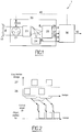
- the figure 1 illustrates a device for estimating the wavefront deformations of an optical system or an object observed by an optical system.
- Incidental and / or positioning deformations of an optical system 20 are estimated by an analytical method implemented in computing means 30 of the device 1.
- the aberrations thus estimated 40 can then optionally be re-directed to the optical system 20 to be corrected.
- the analytical method also makes it possible to restore the object 50.
- observation instrument may be monolithic or with a segmented pupil 21.
- the device may be downstream of a recombination system of the beams 23.
- a diversity image is an image in which a known diversity deformation is added.
- the aberrant phase on the imaging sensor may be different from that seen by the sensor, denoted ⁇ S.
- the measurement method does not require the introduction of a reference source; the images are therefore directly derived from the observed object.
- the wavefront aberration measurement is based on the use of the acquired images which contain the aberrant phase ⁇ S as well as the diversity deformations.
- the aberrations thus estimated 40 may then possibly be corrected by correction means 22, for example a deformable mirror.
- the acquired images are modeled as a function of the sought-after deformations, of the object, as well as of all the relevant physical parameters, such as the introduced phase modulation and the optical detection characteristics of the optical system.
- a plan of diversity can be an extra-focal plane, the deformation of known diversity is then in this case a defocusing.
- the deformation of diversity may be any.
- the figure 2 illustrates an embodiment for estimating the observed object.
- At least two diversity images are generated 25, either on separate sensors or on the same sensor. In the latter case, the acquisition of the images can be done sequentially.
- the figure 2 illustrates a chronogram of image acquisition sequentially.
- the block 25 involves in the optical train any system for introducing a diversity deformation.
- a system can be a membrane, a bimorph mirror, an electro-optical system, etc.
- the method for estimating the observed object is implemented by means of a dedicated printed circuit which takes into account the parameters of the optical system (shape of the pupil, observation wavelength, etc.) and which allows to estimate the observed object 50 on all the frames of two images (see figure 2 ).
- p be the transmission of the pupillary configuration, composed of N T sub-pupils placed at the position u n and each having a phase denoted ⁇ n .
- the pupil transmission is perfect and is worth 1.
- the shape of the pupil or sub-pupils can be arbitrary, for example circular, hexagonal or square, etc.
- Equations (1) and (2) allow to decompose the pupil and the phase in a base known in advance. It remains to find the coefficients kn of this double decomposition.
- N a 18
- N T is the number of sub-pupils
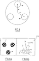
- the optical transfer function has a central peak, sum of N T individual peaks plus N T (N T -1) satellite peaks.
- N T the optical transfer function
- the measurement principle is based on the fact that one will look for the deformations and / or the object producing a model closest to the images acquired, which amounts to minimizing a distance criterion J between the reconstructed model and the data obtained. in each plane.
- the criterion is, for example, quadratic.
- equation (8) is non-linear in phase but quadratic in object.
- equation (8) is non-linear in phase but quadratic in object.
- o ⁇ m ⁇ S 0 ⁇ and ⁇ ⁇ 2 S 0 ⁇ are terms related to a possible regularization on the object (if there is no regularization, these terms are equal to zero); in addition ⁇ ⁇ 2 S 0 ⁇ is the ratio of the spectral power densities of the noise ( ⁇ 2 ) and the object (S 0 ( ⁇ )) weighted
- the measurement method uses an analytical algorithm developed under the assumption of weak phases ⁇ S on the ASO.
- this algorithm is used around an operating point, that is to say around ⁇ S - ⁇ C , or for example with aberrant phase ⁇ low (operating point close to zero).
- N i be the number of pixels in the image, typically 128 ⁇ 128 or 256 ⁇ 256.
- the digitized transfer function that is to say defined in a space compatible with that of the recorded image, thus pixelated, is defined on N f frequencies, with N f ⁇ N i .
- the matrix A is thus of size N f ⁇ N a and B is of size N f ⁇ 1.
- R AT H B or refers to the real party operator.
- the inversion of the matrix A H A is not dimensioning since of size N a ⁇ N a and that N has ⁇ N f ; the calculation time is then reduced to the time required to perform the N d Fourier transforms.
- the figure 5 illustrates the estimator 30 (as noted on the figure 1 ).
- the estimator 30 (as noted on the figure 1 ).
- two diversity images noted 26 and 27 an embodiment, that allowing the estimation of the pistons and higher modes (first-order development as a function of a, therefore).
- the aberrations can be found by applying a reconstructor R to an error signal derived from the diversity images; R is then pre-defined and calculated once and for all for all the physical parameters defining the system; it should be noted that in this case, the object initially taken into account is a medium object, requiring a priori knowledge of the scenes that will be observed.
- this object can be adjusted as the loop stabilizes.
- the reconstructor is determined in advance: the models that will be associated with the images, of size N a ⁇ N f , are calculated under the assumption of weak phase ⁇ S on the ASO by combination 31 of the functions transfer 31.1 and 31.2 obtained in the two diversity plans. We then obtain two matrices 31.3 and 31.4.
- the sub-reconstructor 31.3 is multiplied matricially to the Fourier transform of the image 27; the same operation is performed between the matrix 31.4 and the image 26.
- the two resulting matrices 32 and 33 are then subtracted in order to obtain the function x, which used to infer the desired 40 to 34 aberrations.
- the images can also be used to adjust the object used in the reconstructor (hence the dots shown on the figure 6 ).
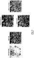
- the figure 7 illustrates the estimation of the object observed by an optical system consisting of eighteen sub-pupils.
- This pupil (composed of sub-pupils) is very close to that of a monolithic telescope, which shows that the current device could be applied to such a telescope with hexagonal sub-pupils for example.
- Two images are simulated from this phase hypothesis on the instrument and a reference object: an image in the focal plane and an image in a defocused plane of 1 rad rms, with a good signal-to-noise ratio.
- the object is then reconstructed by deconvolving the measured image in the focal plane, using the estimated phase.
- the figure 7 shows that the object thus estimated by simple digital processing is very close to the observed object, in particular that the details (cars on the parking for example) are much sharper than on the focal image without treatment.
Description
La présente invention est relative à un procédé et à un dispositif pour l'estimation d'au moins une déformation du front d'onde d'un système optique ou d'un objet observé par le système optique.The present invention relates to a method and a device for estimating at least one distortion of the wavefront of an optical system or an object observed by the optical system.
L'invention trouve notamment application dans le domaine de l'imagerie à haute résolution et de la mise en forme de faisceaux.The invention is particularly applicable in the field of high resolution imaging and beam shaping.
Les déformations peuvent être introduites par un système optique et/ou par le milieu de propagation de la lumière. En outre, lorsque le système optique est dégradé par des déformations, l'invention permet l'estimation (restauration) de l'objet observé.The deformations can be introduced by an optical system and / or by the light propagation medium. In addition, when the optical system is degraded by deformations, the invention allows the estimation (restoration) of the object observed.
La qualité des images obtenues par un instrument optique est souvent dégradée à cause de la présence d'aberrations ou d'autres perturbations sur le trajet de l'onde provenant de l'objet observé.The quality of the images obtained by an optical instrument is often degraded because of the presence of aberrations or other perturbations in the path of the wave coming from the observed object.
En effet, ces déformations de phase présentes dans la pupille de l'instrument, atténuent la fonction de transfert.Indeed, these phase deformations present in the pupil of the instrument, attenuate the transfer function.
Plusieurs dispositifs appelés Analyseurs de Surface d'Onde (ASO) ont été développés pour mesurer la phase pupillaire en la transformant en variations d'intensité mesurables.Several devices called Wave Surface Analyzers (ASO) have been developed to measure the pupil phase by transforming it into measurable intensity variations.
Utilisés dans un système fonctionnant en boucle fermée avec un élément pouvant contrôler la phase de l'onde reçue (miroir déformable, déphaseurs, etc.), ces dispositifs permettent de s'affranchir des perturbations observées. Par ailleurs, les informations de l'ASO peuvent être utilisées pour restaurer (estimer) l'objet observé.Used in a system operating in a closed loop with an element that can control the phase of the received wave (deformable mirror, phase shifters, etc.), these devices make it possible to overcome the disturbances observed. In addition, ASO information can be used to restore (estimate) the observed object.
Il existe aujourd'hui une large gamme d'ASO, on pourra notamment se référer à
Pour corriger les aberrations d'un système optique à pupille quelconque, c'est-à-dire soit monolithique, soit constituée d'un ensemble de sous pupilles jointives ou non, les techniques dites plan focal apparaissent comme des solutions séduisantes.To correct the aberrations of an optical system with any pupil, that is to say either monolithic, or consisting of a set of contiguous sub-pupils, the so-called focal plane techniques appear as seductive solutions.
En effet, contrairement aux dispositifs plan pupille qui doivent extraire une partie de la lumière vers une optique auxiliaire (ce qui complexifie le montage optique), les méthodes plan focal permettent la mesure des déformations du front d'onde ainsi que la combinaison de toutes les sous-pupilles en une seule trame, et ce avec un design opto-mécanique simple.In fact, unlike the pupil plane devices which must extract a part of the light towards an auxiliary optics (which complicates the optical assembly), the focal plane methods make it possible to measure the deformations of the wavefront as well as the combination of all the sub-pupils in a single frame, with a simple opto-mechanical design.
Puisque les instruments imageurs sont naturellement équipés d'une caméra en plan focal, il est avantageux d'utiliser un ASO au voisinage de cette caméra pour mesurer les déformations de l'instrument Un dispositif plan focal est divulgué dans le document
Dans le cas contraire, ou pour une observation sur objet étendu, la seule donnée de l'image focale est insuffisante pour retrouver de manière unique les aberrations.In the opposite case, or for an observation on an extended object, the only data of the focal image is insufficient to uniquely find the aberrations.
Dans un cas général (objet inconnu et/ou configuration quelconque), il est possible de lever l'indétermination sur la phase en utilisant plusieurs images dites de diversité obtenues au voisinage du plan focal en présence d'une déformation (ou modulation) de phase parfaitement connue ; le plus souvent, il s'agit d'une (voire de plusieurs) image(s) défocalisée(s) pour des raisons de simplicité de mise en oeuvre.In a general case (unknown object and / or any configuration), it is possible to lift the indeterminacy on the phase by using several so-called diversity images obtained near the focal plane in the presence of a deformation (or modulation) phase perfectly known; most often, it is a (or more) defocused image (s) for reasons of simplicity of implementation.
L'estimation de la phase aberrante est alors fondée sur une approche qui consiste à choisir les aberrations qui minimisent un critère de distance aux images.The estimation of the aberrant phase is then based on an approach that consists in choosing the aberrations that minimize a distance criterion to the images.
On recherche donc les déformations qui produisent un modèle d'image le plus proche des données, la minimisation étant généralement effectuée dans le plan de Fourier.We therefore look for the deformations that produce an image model closest to the data, the minimization being generally carried out in the Fourier plane.
Cette méthode dite de la diversité de phase, en anglais, « phase diversity », est communément appliquée à la mesure de phase sur objet étendu.This so-called phase diversity method is commonly applied to extended object phase measurement.
Toutefois, cette méthode permet d'estimer l'objet observé. En d'autres termes, on restaure l'objet observé en s'affranchissant des déformations.However, this method makes it possible to estimate the observed object. In other words, we restore the object observed by freeing deformations.
Cependant, que ce soit pour l'estimation de l'objet ou des aberrations, une telle méthode nécessite des temps de calcul importants qui sont difficilement compatibles avec les exigences d'un système d'estimation en temps-réel.However, whether for estimating the object or aberrations, such a method requires significant computation times that are difficult to match the requirements of a real-time estimation system.
En effet, si N est le nombre d'images acquises par diversité, 2N transformées de Fourier sont au minimum effectuées à chaque itération, sachant qu'une cinquantaine d'itérations peuvent être nécessaires en pratique.Indeed, if N is the number of images acquired by diversity, 2N Fourier transforms are at least performed at each iteration, knowing that fifty or so iterations may be necessary in practice.
Plusieurs travaux ont donc été menés afin de réduire le nombre d'itérations nécessaires :
- tout d'abord en essayant de trouver de meilleurs algorithmes de minimisation pour des tests de simulation effectués sur des configurations monolithiques,
- puis par modification du critère utilisé, avec des études réalisées pour un télescope monolithique ou segmenté.
- first by trying to find better minimization algorithms for simulation tests performed on monolithic configurations,
- then by modification of the criterion used, with studies carried out for a monolithic or segmented telescope.
Ces procédés nécessitent plusieurs itérations avant de converger et présentent donc des temps de calcul qui augmentent avec le nombre d'aberrations à rechercher. Les temps de calcul pour estimer l'objet observé sont par conséquent également importants.These processes require several iterations before converging and therefore have computation times that increase with the number of aberrations to be searched. Calculation times for estimating the observed object are therefore also important.
La mesure des faibles aberrations (c'est-à-dire résiduelles) en boucle fermée a parfois été réalisée mais seulement pour des configurations monolithiques (c'est-à-dire pour la mesure des déformations d'ordre supérieur à la défocalisation) et sans aucune caractérisation fine des performances du capteur.The measurement of small aberrations (that is to say residuals) in closed loop has sometimes been done but only for monolithic configurations (that is to say for the measurement of higher order deformations than defocusing) and without any fine characterization of the sensor performance.
Tous ces procédés itératifs nécessitent donc des puissances de calcul significatives.All these iterative methods therefore require significant computing power.
Or l'utilisation de processeurs adéquats, ne posant a priori pas de problème pour des instruments au sol, devient critique pour des applications embarquées où la puissance du calculateur est limitée.Now the use of suitable processors, posing a priori no problem for ground-based instruments, becomes critical for embedded applications where the power of the computer is limited.
L'invention vise à estimer des déformations d'un front d'onde d'un système d'observation ou de l'objet observé par le système à partir d'une ou plusieurs images prises au voisinage du plan focal d'un système d'observation au moyen d'un procédé non itératif mais purement analytique.The aim of the invention is to estimate deformations of a wavefront of an observation system or of the object observed by the system from one or more images taken in the vicinity of the focal plane of a radar system. observation by means of a non-iterative but purely analytical process.
Ainsi selon un premier aspect, l'invention concerne un procédé d'estimation d'au moins une déformation du front d'onde d'un système d'observation ou d'un objet observé par le système.Thus according to a first aspect, the invention relates to a method for estimating at least one wavefront deformation of an observation system or an object observed by the system.
En particulier, le procédé de l'invention est caractérisé en ce que : on acquiert, au voisinage du plan focal du système d'observation, au moins une image de diversité dans au moins un plan de diversité, l'image de diversité comprenant une déformation de diversité connue ; et en ce que dans chaque plan de diversité ; on détermine un modèle d'image fondé sur au moins: une décomposition de la transmission pupillaire de la pupille physique du système en une pluralité de sous-pupilles ; une décomposition sur chaque sous-pupilles de la déformation recherchée sous la forme d'au moins une déformation connue pondérée par des coefficients à déterminer ; une détermination de la fonction de transfert optique du système par autocorrélation de la transmission pupillaire de sa pupille ; la linéarisation, dans dite fonction de transfert optique, de chacun des termes de l'autocorrélation en fonction des coefficients de la déformation recherchée, la linéarisation étant effectuée au voisinage de la déformation de diversité connue ; l'objet observé et du bruit ; et en ce que à partir du ou des modèle(s) d'image(s) déterminé(s) et de la ou les image(s) acquise(s), on estime la ou les déformation(s) recherchée(s) ou l'objet observé.In particular, the method of the invention is characterized in that, in the vicinity of the focal plane of the observation system, at least one diversity image is acquired in at least one diversity plane, the diversity image comprising a deformation of known diversity; and in that in every plane of diversity; determining an image model based on at least: a decomposition of the pupillary transmission of the physical pupil of the system into a plurality of sub-pupils; a decomposition on each sub-pupil of the desired strain in the form of at least one known deformation weighted by coefficients to be determined; a determination of the optical transfer function of the system by autocorrelation of the pupillary transmission of its pupil; linearization, in said optical transfer function, of each of the terms of the autocorrelation as a function of the coefficients of the desired deformation, the linearization being carried out in the vicinity of the known diversity deformation; the observed object and noise; and in that from the determined image model (s) and the acquired image (s), the desired deformation (s) is estimated or the object being observed.
Le modèle d'image est en outre fonction de l'objet observé par le système et de la fonction de transfert linéarisée.The image model is also a function of the object observed by the system and the linearized transfer function.
Le procédé de l'invention s'applique à un objet étendu et ne nécessite aucune itération minimisant par conséquent le temps de calcul.The method of the invention applies to an extended object and does not require any iteration thereby minimizing the computation time.
Le procédé de l'invention est fondé sur la linéarisation de la fonction de transfert du système d'observation. Une telle linéarisation permet d'obtenir une estimation des déformations ou de l'objet observé.The method of the invention is based on the linearization of the transfer function of the observation system. Such linearization makes it possible to obtain an estimate of the deformations or the object observed.
En particulier, la fonction de transfert du système d'observation est linéarisée dans chaque plan de diversité et est au moins fonction de la ou les déformation(s) recherchée(s) et de la déformation de diversité connue associée à chaque plan de diversité.In particular, the transfer function of the observation system is linearized in each diversity plane and is at least a function of the desired deformation (s) and the known diversity deformation associated with each diversity plane.
Avec les solutions telles que connues il est possible d'estimer les déformations mais avec des temps calcul conséquent du fait que dans ces solutions l'estimation est fondée sur la minimisation d'un critère de distance, effectuée de manière itérative. En outre, avec ces solutions il n'est pas possible d'estimer directement l'objet observé en une itération.With the solutions as known it is possible to estimate the deformations but with calculating times because of the fact that in these solutions the estimate is based on the minimization of a distance criterion, performed iteratively. In addition, with these solutions it is not possible to directly estimate the observed object in an iteration.
Le fait d'utiliser un modèle d'image qui dépend de la fonction de transfert du système linéarisée dans chaque plan de diversité du système permet de simplifier le système d'équations à deux inconnues (l'objet et les perturbations) afin de résoudre sans itération, ou l'objet ou les perturbations (la phase).Using an image model that depends on the transfer function of the linearized system in each diversity plane of the system makes it possible to simplify the system of equations with two unknowns (the object and the perturbations) in order to solve without iteration, or the object or disturbances (the phase).
De manière préférée, le système d'observation est un système d'observation optique et la fonction de transfert du système est la fonction de transfert optique, imagerie acoustique.In a preferred manner, the observation system is an optical observation system and the transfer function of the system is the optical transfer function, acoustic imaging.
En outre, selon un second aspect, l'invention concerne un dispositif d'estimation d'au moins une déformation du front d'onde d'un système d'observation ou d'un objet observé par le système.In addition, according to a second aspect, the invention relates to a device for estimating at least one deformation of the wavefront of an observation system or an object observed by the system.
Le dispositif de l'invention est caractérisé en ce qu'il comprend des moyens pour acquérir, au voisinage du plan focal du système d'observation, au moins une image de diversité dans au moins un plan de diversité, l'image de diversité comprenant une déformation de diversité connue ; et en ce que dans chaque plan de diversité le dispositif comprend : des moyens pour déterminer un modèle d'image fondé sur au moins : une décomposition de la pupille physique du système en une pluralité de sous-pupilles ; une décomposition sur chaque sous-pupilles de la déformation recherchée sous la forme d'au moins une déformation connue pondérée par des coefficients à déterminer ; une détermination de la fonction de transfert du système par autocorrélation de sa pupille ; la linéarisation de chacun des termes de l'autocorrélation en fonction des coefficients de la déformation recherchée, la linéarisation étant effectuée au voisinage de la déformation de diversité connue ; l'objet observé et du bruit ; et en ce que à partir du ou des modèle(s) d'image(s) déterminé(s) et de la ou les image(s) acquise(s), on estime la ou les déformation(s) recherchée(s) ou l'objet observé.The device of the invention is characterized in that it comprises means for acquiring, in the vicinity of the focal plane of the observation system, at least one diversity image in at least one diversity plane, the diversity image comprising a known diversity deformation; and in that in each diversity plane the device comprises: means for determining an image model based on at least: a decomposition of the physical pupil of the system into a plurality of sub-pupils; a decomposition on each sub-pupil of the desired strain in the form of at least one known deformation weighted by coefficients to be determined; a determination of the transfer function of the system by autocorrelation of its pupil; the linearization of each of the autocorrelation terms as a function of the coefficients of the desired deformation, the linearization being carried out in the vicinity of the known diversity deformation; the observed object and noise; and in that from the determined image model (s) and the acquired image (s), the desired deformation (s) is estimated or the object being observed.
Du fait que le dispositif est adapté pour mettre en oeuvre un procédé ne nécessitant pas d'itération, il respecte de fortes contraintes temps réel et s'intègre parfaitement dans des systèmes embarqués.Because the device is adapted to implement a process that does not require iteration, it respects strong real-time constraints and integrates perfectly into embedded systems.
Le dispositif de l'invention peut être utilisé en boucle fermée en conjonction avec des moyens de correction, pour la correction temps réel des déformations du front d'onde d'un système optique et/ou pour estimer en outre l'objet observé par le système d'observation.The device of the invention can be used in closed loop in conjunction with correction means, for the real time correction of the wavefront deformations of an optical system and / or to estimate further the object observed by the observation system.
Enfin, l'invention concerne selon un troisième aspect un système embarqué comprenant des moyens pour mettre en oeuvre le procédé selon le premier aspect de l'invention.Finally, according to a third aspect, the invention relates to an embedded system comprising means for implementing the method according to the first aspect of the invention.
D'autres caractéristiques et avantages de l'invention ressortiront encore de la description qui suit laquelle est purement illustrative et non limitative et doit être lue en regard des dessins annexés sur lesquels :
- la
figure 1 illustre un dispositif d'estimation des déformations du front d'onde conforme à l'invention ; - la
figure 2 illustre une variante du dispositif de l'invention pour l'estimation de l'objet observé ; - la
figure 3 illustre une configuration à trois sous-pupilles ; - les
figures 4a et 4b illustrent respectivement une configurations à trois sous-pupilles d'un système optique et la fonction de transfert associée à aberrations nulles ; - la
figure 5 illustre un premier mode de réalisation du procédé de l'invention pour l'estimation des déformations ; - la
figure 6 illustre un second mode de réalisation du procédé de l'invention pour l'estimation des déformations ; - la
figure 7 illustre l'estimation de l'objet observé pour une configuration à 18 sous-pupilles approximant un télescope monolithique.
- the
figure 1 illustrates a device for estimating the wavefront deformations according to the invention; - the
figure 2 illustrates a variant of the device of the invention for estimating the object observed; - the
figure 3 illustrates a configuration with three sub-pupils; - the
Figures 4a and 4b respectively illustrate three sub-pupil configurations of an optical system and the transfer function associated with null aberrations; - the
figure 5 illustrates a first embodiment of the method of the invention for estimating deformations; - the
figure 6 illustrates a second embodiment of the method of the invention for estimating deformations; - the
figure 7 illustrates the observed object estimate for a 18 sub-pupil configuration approximating a monolithic telescope.
La
Les déformations incidentes et/ou de positionnement 10 d'un système optique 20 (représenté ici à titre d'exemple comme étant un instrument d'imagerie optique) sont estimées par un procédé analytique implémenté dans des moyens de calcul 30 du dispositif 1.Incidental and / or positioning deformations of an optical system 20 (here shown by way of example as an optical imaging instrument) are estimated by an analytical method implemented in computing means 30 of the
Les aberrations ainsi estimées 40 peuvent alors éventuellement être re-dirigées vers le système optique 20 pour être corrigées.The aberrations thus estimated 40 can then optionally be re-directed to the
Le procédé analytique permet également de restaurer l'objet 50.The analytical method also makes it possible to restore the
Notons que l'instrument d'observation peut être monolithique ou à pupille segmentée 21.Note that the observation instrument may be monolithic or with a
Dans le cas à pupille segmentée, le dispositif peut être en aval d'un système de recombinaison des faisceaux 23.In the segmented pupil case, the device may be downstream of a recombination system of the
Un senseur 25, installé ici au voisinage d'un capteur d'imagerie 24, génère au moins une image de diversité 26 dans des conditions de phase parfaitement connues.A
On note que si l'objet est inconnu, plusieurs images de diversité 27, 28, sont nécessaires.Note that if the object is unknown,
Une image de diversité est une image dans laquelle on ajoute une déformation de diversité connue.A diversity image is an image in which a known diversity deformation is added.
Du fait des aberrations présentes sur le trajet optique de la lumière, la phase aberrante sur le capteur d'imagerie, notée φC, peut être différente de celle vue par le senseur, notée φS.Due to the aberrations present in the optical path of the light, the aberrant phase on the imaging sensor, noted φ C , may be different from that seen by the sensor, denoted φ S.
L'objet observé pouvant être quelconque, le procédé de mesure ne nécessite pas l'introduction d'une source de référence ; les images sont donc directement issues de l'objet observé.Since the observed object may be arbitrary, the measurement method does not require the introduction of a reference source; the images are therefore directly derived from the observed object.
Elles sont acquises aux moyens d'un ou plusieurs capteurs, par exemple composés de matrices de type CCD ou CMOS, de préférence avec un échantillonnage à Shannon.They are acquired by means of one or more sensors, for example composed of matrices of CCD or CMOS type, preferably with Shannon sampling.
Il est à noter qu'à partir d'un objet observé on peut :
- acquérir une image à partir de laquelle on va ajouter une ou plusieurs déformation(s) connue(s) de manière à obtenir les images de diversité,
- acquérir simultanément (si possible ou au pire pendant un temps suffisamment court) autant d'image de diversité que l'on souhaite.
- acquire an image from which we will add one or more known deformation (s) so as to obtain the diversity images,
- acquire simultaneously (if possible or at worst for a sufficiently short time) as much diversity image as one wishes.
La mesure des aberrations du front d'onde repose sur l'utilisation des images acquises qui contiennent la phase aberrante φS ainsi que les déformations de diversité.The wavefront aberration measurement is based on the use of the acquired images which contain the aberrant phase φ S as well as the diversity deformations.
Les aberrations ainsi estimées 40 peuvent alors éventuellement être corrigées par des moyens de correction 22, par exemple un miroir déformable.The aberrations thus estimated 40 may then possibly be corrected by correction means 22, for example a deformable mirror.
Au cours du procédé on modélise les images acquises en fonction des déformations recherchées, de l'objet, ainsi que de l'ensemble des paramètres physiques pertinents comme la modulation de phase introduite et les caractéristiques optiques de détection du système optique.During the process, the acquired images are modeled as a function of the sought-after deformations, of the object, as well as of all the relevant physical parameters, such as the introduced phase modulation and the optical detection characteristics of the optical system.
Par la suite, nous allons nous placer dans un plan de diversité noté d introduisant une phase φd parfaitement connue et nous considérerons des déformations produisant une phase φa (respectivement φdn et φan sur chaque sous-pupille).Subsequently, we will place ourselves in a diversity plan noted d introducing a phase φ d perfectly known and we will consider deformations producing a phase φ a (respectively φ dn and φ an on each sub-pupil).
Il est entendu par plan de diversité d, l'endroit on l'on acquiert une image de diversité.It is understood by diversity plan d, where one acquires an image of diversity.
Il s'agit par conséquent d'une image focale en présence d'une éventuelle aberration additionnelle connue, comme par exemple une défocalisation. Un plan de diversité peut dans ce cas là être un plan extra-focal, la déformation de diversité connue est alors dans ce cas là une défocalisation.It is therefore a focal image in the presence of any known additional aberration, such as a defocusing. In this case, a plan of diversity can be an extra-focal plane, the deformation of known diversity is then in this case a defocusing.
Toutefois, la déformation de diversité peut-être quelconque.However, the deformation of diversity may be any.
La
Au moins deux images de diversité sont générées 25, soit sur des capteurs séparés, soit sur le même capteur. Dans ce dernier cas, l'acquisition des images peut être faite de manière séquentielle. La
Le procédé d'estimation de l'objet observé est mis en oeuvre au moyen d'un circuit imprimé dédié qui prend en compte les paramètres du système optique (forme de la pupille, longueur d'onde d'observation, etc.) et qui permet d'estimer l'objet observé 50 sur toutes les trames de deux images (voir
La
Soit p la transmission de la configuration pupillaire, composée de NT sous-pupilles placées à la position un et présentant chacune une phase notée φn.Let p be the transmission of the pupillary configuration, composed of N T sub-pupils placed at the position u n and each having a phase denoted φ n .
La transmission pupillaire est donnée par : ![]()
![]()
On note que la décomposition ci-dessus mentionnée (cf. équation (1)) est également effectuée même si l'instrument ne comporte qu'une seule pupille.Note that the decomposition mentioned above (see equation (1)) is also performed even if the instrument has only one pupil.
Si la phase aberrante est nulle, la transmission de la pupille est parfaite et vaut 1.If the aberrant phase is zero, the pupil transmission is perfect and is worth 1.
Il est à noter que la forme de la pupille ou des sous-pupilles peut être quelconque, par exemple circulaire, hexagonale ou carré, etc.It should be noted that the shape of the pupil or sub-pupils can be arbitrary, for example circular, hexagonal or square, etc.
Les phases aberrantes peuvent être exprimées dans différentes bases de déformations connues, par exemple la base des polynômes de Zernike : ![]()
![]()
Les équations (1) et (2) permettent de décomposer la pupille et la phase dans une base connue à l'avance. Il reste alors à chercher les coefficients akn de cette double décomposition.Equations (1) and (2) allow to decompose the pupil and the phase in a base known in advance. It remains to find the coefficients kn of this double decomposition.
Par la suite, on notera a le vecteur de taille Na × 1 dont les éléments akn sont les aberrations recherchées, Na étant le nombre d'inconnues cherchées égal à NTxNZ. Par exemple, pour un instrument à six sous-pupilles (NT=6) sur lequel on recherche les trois premiers (NZ=3) ordres de Zernike on a Na = 18.Subsequently, we note a vector of size N a × 1 whose elements a kn are the desired aberrations, N a being the number of unknowns sought equal to N T xN Z. For example, for an instrument with six sub-pupils (N T = 6) on which one looks for the first three (N Z = 3) orders of Zernike we have N a = 18.
Dans le plan fréquentiel, la fonction de transfert optique Fd obtenue au dième plan de diversité est donnée par l'autocorrélation de la pupille : ![]()
![]()
Il est à noter que si NT est le nombre de sous-pupilles, la fonction de transfert optique présente un pic central, somme de NT pics individuels plus NT(NT-1) pics satellitaires. En outre, il est à noter que l'on peut également décomposer une pupille en une pluralité de sous-pupilles.It should be noted that if N T is the number of sub-pupils, the optical transfer function has a central peak, sum of N T individual peaks plus N T (N T -1) satellite peaks. In addition, it should be noted that a pupil can also be broken down into a plurality of sub-pupils.
Chaque pic P0, P1, ..., P6, dans le cas où NT=3, de la fonction de transfert optique telle qu'illustrée par la
- une fonction Fd,n,n' contenant seulement les aberrations de diversité d (Fd,n,n' représente donc le pic d'intercorrélation non aberré),
- une fonction Ψ dépendant des aberrations recherchées et de la diversité.
- a function F d, n, n ' containing only the aberrations of diversity d (F d, n, n' represents therefore the peak of non-aberrant intercorrelation),
- a function Ψ depending on the desired aberrations and diversity.
Si la phase sur le senseur φS est faible, il est possible d'écrire chaque pic de la fonction de transfert optique comme : ![]()
![]()
Si l'on recherche pistons et modes supérieurs, on peut développer l'expression de Ψa au premier ordre au voisinage des aberrations de diversité de la manière suivante : 
Si seuls les pistons sont appliqués/recherchés, alors l'expression de la fonction de transfert optique dans chaque plan de diversité est exacte et a pour expression : 
Il existe donc un lien direct entre la forme de la fonction de transfert optique et les déformations que l'on recherche.There is therefore a direct link between the shape of the optical transfer function and the deformations that one seeks.
Une fois le vecteur x déterminé par le procédé décrit ci-dessus et compte tenu des deux cas explicités ci-dessus, les aberrations se déduisent de x par les équations (5) et (6).Once the vector x determined by the method described above and considering the two cases explained above, the aberrations are deduced from x by the equations (5) and (6).
La transformée de Fourier de l'image obtenue au dième plan de diversité est donnée par : ![]()
![]()
![]()
![]()
Le principe de mesure repose sur le fait que l'on va chercher les déformations et/ou l'objet produisant un modèle le plus proche des images acquises, ce qui revient à minimiser un critère de distance J entre le modèle reconstruit et les données obtenues dans chaque plan. Le critère est par exemple quadratique.The measurement principle is based on the fact that one will look for the deformations and / or the object producing a model closest to the images acquired, which amounts to minimizing a distance criterion J between the reconstructed model and the data obtained. in each plane. The criterion is, for example, quadratic.
Dans le domaine de Fourier, ce critère s'écrit : ![]()
![]()
Bien que l'objet soit généralement inconnu, il est possible de l'exprimer à phase aberrante fixée et par conséquent de s'affranchir de ce dernier. En effet, l'équation (8) est non linéaire en phase mais quadratique en objet. Ainsi à phase fixée, il existe une solution analytique pour l'objet qui est donnée par : 
![]()
![]()


![]()
![]()
A partir de l'équation (8) il est possible d'obtenir un nouveau critère J' qui ne dépend plus explicitement que des déformations recherchées : 
De manière générale, la minimisation du critère J' est effectuée itérativement avec des temps de calcul significatifs.In general, the minimization of the criterion J 'is performed iteratively with significant computation times.
En remplacement de l'algorithme itératif, le procédé de mesure utilise un algorithme analytique développé dans l'hypothèse des faibles phases φS sur l'ASO.As a replacement for the iterative algorithm, the measurement method uses an analytical algorithm developed under the assumption of weak phases φ S on the ASO.
En particulier, cet algorithme est utilisé autour d'un point de fonctionnement, c'est-à-dire autour de φS - φC, ou par exemple à phase aberrante φ faible (point de fonctionnement proche de zéro).In particular, this algorithm is used around an operating point, that is to say around φ S - φ C , or for example with aberrant phase φ low (operating point close to zero).
Ainsi, dans le cadre de l'hypothèse φS faible, il est possible de :
- développer le dénominateur du critère J' à l'ordre zéro, ce qui revient à le considérer comme un terme de pondération indépendant des déformations recherchées,
- exprimer le modèle de formation d'image comme une fonction simple des aberrations, ce qui revient à linéariser dans chaque plan les pics de la fonction de transfert optique au voisinage des aberrations fixes de diversité, en d'autres termes cela revient à linéariser la fonction de transfert optique donnée par l'équation (3).
- to develop the denominator of the criterion J 'to zero order, which amounts to considering it as a weighting term independent of the deformations sought,
- expressing the imaging model as a simple function of aberrations, which amounts to linearizing in each plane the peaks of the optical transfer function in the neighborhood of the fixed aberrations of diversity, in other words it amounts to linearizing the function optical transfer given by equation (3).
Contrairement aux techniques connues, la linéarisation de chaque pic permet de prendre en compte des configurations compactes et redondantes (dont les pics de la fonction de transfert optique se recouvrent).Unlike known techniques, the linearization of each peak makes it possible to take into account compact and redundant configurations (whose peaks of the optical transfer function overlap).
On peut exprimer ce critère linéarisé comme : ![]()
![]()
Soit Ni le nombre de pixels dans l'image, typiquement 128 × 128 ou 256 × 256.Let N i be the number of pixels in the image, typically 128 × 128 or 256 × 256.
La fonction de transfert numérisée, c'est-à-dire définie dans un espace compatible avec celui de l'image enregistrée, donc pixellisée, est définie sur Nf fréquences, avec Nf ≤ Ni. La matrice A est donc de taille Nf × Na et B est de taille Nf × 1.The digitized transfer function, that is to say defined in a space compatible with that of the recorded image, thus pixelated, is defined on N f frequencies, with N f ≤ N i . The matrix A is thus of size N f × N a and B is of size N f × 1.
Comme ce nouveau critère est quadratique, les déformées du front d'onde peuvent s'exprimer de manière simple : ![]()
![]()
![]()
![]()
Les aberrations recherchées se déduisent ensuite de x. Pour affiner le critère, il est également possible :
- de prendre en compte des poids différents entre les images ;
- d'introduire un filtrage sur les images ;
- d'inclure une gestion des effets de bord pour des images étendues ;
- d'inclure une recherche des basculements différentiels entre les images de diversité ;
- d'ajouter des termes de régularisation.
- to take into account different weights between the images;
- to introduce filtering on the images;
- include edge effects management for extended images;
- to include a search for differential switching between diversity images;
- to add regulation terms.
Tout « raffinement » effectué se traduit par une modification des matrices A et B qui vont intervenir, mais le principe de base du procédé de mesure est inchangé.Any "refinement" performed results in a modification of matrices A and B that will occur, but the basic principle of the measurement method is unchanged.
Ci-dessus nous avons vu qu'à partir du critère on peut retrouver les aberrations ; en effet nous nous sommes affranchi de l'objet dans l'équation (9) en l'exprimant à phase aberrante fixée et en le réinjectant dans le critère initial donné par l'équation (8).Above we have seen that from the criterion we can find the aberrations; indeed we have freed ourselves from the object in equation (9) by expressing it with a fixed aberrant phase and re-injecting it into the initial criterion given by equation (8).
Si l'on recherche les pistons et d'autres aberrations, nous avons montré, lors du cas n°1, précédemment présenté, que l'on pouvait développer la fonction de transfert optique au premier ordre en x = a, ainsi on pose : 
L'expression des matrices A et B est alors : ![]()


![]()
Avec l'équation (12), le coût de calcul est bien moins important que dans le cas itératif.With equation (12), the calculation cost is much less important than in the iterative case.
En effet, l'inversion de la matrice AHA n'est pas dimensionnante puisque de taille Na×Na et que Na<<Nf; le temps de calcul se résume alors au temps nécessaire pour effectuer les Nd transformées de Fourier.Indeed, the inversion of the matrix A H A is not dimensioning since of size N a × N a and that N has << N f ; the calculation time is then reduced to the time required to perform the N d Fourier transforms.
La
Le procédé d'estimation des aberrations effectue dans chaque plan de diversité :
- le calcul des matrices L1,
L 2 31 et M1,M 2 32, - L1 et L2 sont ensuite multipliées à la transformée de Fourier des
images 27et 26, - le symbole ⊙ désignant une opération linéaire, comme le produit terme à terme ou une succession d'opérations linéaires,
- le même type d'opération est effectué avec M 1 et M 2. On obtient ainsi en sortie les matrices A 12, A 21, 33 de taille Nf × Na ainsi que les matrices B 12,
B 21 34 de taille Nf × 1, d'après l'équation 10, les matrices résultantes sont ensuite soustraites pour former les matrices A 35et B 36,l'opération 37 calcule le terme
- comme dans le cadre de ce mode de réalisation a = x, les aberrations recherchées sont directement obtenues en sortie de l'opérateur 37.
- calculating the matrices L 1 ,
L 2 31 and M 1 ,M 2 32, - L 1 and L 2 are then multiplied to the Fourier transform of
images - the symbol ⊙ denoting a linear operation, such as the term futures product or a series of linear operations,
- the same type of operation is performed with M 1 and M 2 . The matrices A 12 , A 21 , 33 of size N f × N a are thus obtained as well as matrices B 12 ,
B 21 34 of size N f × 1, - according to
equation 10, the resulting matrices are then subtracted to formmatrices A 35 andB 36, -
operation 37 calculates the term - as in the context of this embodiment a = x, the desired aberrations are directly obtained at the output of the
operator 37.
Le processus d'estimation des aberrations décrit au dessus peut également être vu d'une autre manière.The aberration estimation process described above can also be seen in another way.
En effet, en partant de l'expression des aberrations estimées (voir équation 12), il est possible d'exprimer analytiquement certains termes.Indeed, starting from the expression of the estimated aberrations (see equation 12), it is possible to express analytically certain terms.
En particulier, on peut retrouver les aberrations par l'application d'un reconstructeur R à un signal d'erreur issu des images de diversité ; R est alors pré-défini et calculé une fois pour toutes pour l'ensemble des paramètres physiques définissant le système ; il est à noter que dans ce cas, l'objet initialement pris en compte est un objet moyen, nécessitant une connaissance a priori des scènes qui vont être observées.In particular, the aberrations can be found by applying a reconstructor R to an error signal derived from the diversity images; R is then pre-defined and calculated once and for all for all the physical parameters defining the system; it should be noted that in this case, the object initially taken into account is a medium object, requiring a priori knowledge of the scenes that will be observed.
On note toutefois que dans le cadre d'une utilisation en boucle fermée, cet objet peut être ajusté au fur et à mesure que la boucle se stabilise.Note however that in the context of a closed-loop operation, this object can be adjusted as the loop stabilizes.
Dans ce cas, on peut simplifier l'équation (12). Les déformations du front d'onde s'expriment alors comme ![]()
![]()
Le procédé d'estimation correspondant, illustré
Dans un premier temps, le reconstructeur est déterminé à l'avance : les modèles qui seront associés aux images, de taille Na × Nf, sont calculés sous l'hypothèse des faibles phase φS sur l'ASO par combinaison 31 des fonctions de transfert 31.1 et 31.2 obtenues dans les deux plans de diversité. On obtient alors deux matrices 31.3 et 31.4.At first, the reconstructor is determined in advance: the models that will be associated with the images, of size N a × N f , are calculated under the assumption of weak phase φ S on the ASO by
Dans un deuxième temps, le sous-reconstructeur 31.3 est multiplié matriciellement à la transformée de Fourier de l'image 27 ; la même opération est effectuée entre la matrice 31.4 et l'image 26.In a second step, the sub-reconstructor 31.3 is multiplied matricially to the Fourier transform of the
Les deux matrices résultantes 32 et 33 sont ensuite soustraites de manière à obtenir la fonction x, qui servira à déduire en 34 les aberrations recherchées 40.The two resulting
Par la suite, les images peuvent également servir à ajuster l'objet utilisé dans le reconstructeur (d'où les pointillés représentés sur la
Nous avons décrit ci-dessus l'utilisation de la linéarisation des pics de la fonction de transfert optique pour la recherche des aberrations, une fois celle-ci déterminée on peut les utiliser pour remonter à l'objet, notamment lorsque ce dernier est inconnu.We have described above the use of the linearization of the peaks of the optical transfer function for the search of the aberrations, once this one determined they can be used to go back to the object, in particular when the latter is unknown.
En utilisant l'expression de l'objet exprimée par l'équation (9) en fonction des aberrations, on peut une fois les aberrations estimées- les réinjecter dans l'expression pour retrouver l'objet.By using the expression of the object expressed by equation (9) as a function of aberrations, we can once the estimated aberrations-reinject them into the expression to find the object.
Il est bien entendu possible d'affiner la recherche de l'objet par une éventuelle opération de filtrage, la gestion des effets de bord, etc.It is of course possible to refine the search for the object by a possible filtering operation, the management of edge effects, etc.
La
On illustre un cas où l'instrument d'observation est affecté par une perturbation de phase égale à λ/10, résultant d'un tirage aléatoire sur huit modes de Zernike (défocalisation, deux astigmatismes, deux comas, deux comas triples, aberration sphérique).We illustrate a case where the observation instrument is affected by a phase perturbation equal to λ / 10, resulting from a random draw on eight modes of Zernike (defocusing, two astigmatisms, two comas, two triple comas, spherical aberration ).
Deux images sont simulées à partir de cette hypothèse de phase sur l'instrument et d'un objet de référence : une image dans le plan focal et une image dans un plan défocalisé de 1 rad rms, avec un bon rapport signal à bruit.Two images are simulated from this phase hypothesis on the instrument and a reference object: an image in the focal plane and an image in a defocused plane of 1 rad rms, with a good signal-to-noise ratio.
A partir de ces deux images, uniquement, la perturbation de phase est estimée sur les sous-pupilles (en piston-tip-tilt uniquement).From these two images, only the phase disturbance is estimated on the sub-pupils (in piston-tip-tilt only).
L'objet est ensuite reconstruit par déconvolution de l'image mesurée en plan focal, en utilisant la phase estimée.The object is then reconstructed by deconvolving the measured image in the focal plane, using the estimated phase.
La
Claims (12)
- Method for estimating at least one deformation (10) of the wave front of an observation system (20) or an object observed by said observation system (20), consisting in that:- at least one diversity image (26-28) is acquired close to the focal plane of the observation system, in at least one diversity plane, the diversity image comprising a deformation with known diversity; and characterised in that in each diversity plane:- a model of an image is determined based on at least-- a decomposition of the pupillary transmission of the physical pupil of the system into a plurality of sub-pupils;-- a decomposition on each sub-pupil of the required deformation in the form of a least one known deformation weighted by coefficients to be determined:-- a determination of the optical transfer function of the system (20) by self-correlation of the pupillary transmission of its pupil;-- linearization of each self-correlation term in said optical transfer function, as a function of the required deformation coefficients, linearization being done close to the deformation with known diversity;- the observed object and noise;and in that the required deformation(s) or the observed object are estimated from the determined image model(s) and the acquired image(s).
- Method according to claim 1, characterised in that the deformation (s) or the object to be estimated minimise(s) a quadratic estimation function.
- Method according to one of the previous claims, characterised in that the sub-pupils are circular or hexagonal or square.
- Method according to one of the previous claims, characterised in that the deformations are expressed in the Zernike base.
- Method according to one of the previous claims, characterised in that the diversity deformation is arbitrary.
- Method according to one of the previous claims, characterised in that the required deformation(s) is or are:- a piston, linearization of the transfer function in each diversity plane is exact;- arbitrary, linearization of the transfer function in each diversity plane is approximate.
- Method according to one of the previous claims, characterised in that it will be used on one or several integrated circuit(s).
- Method according to one of the previous claims, characterised in that the observation system is chosen from among the group composed of the optical observation system, electron microscope, telescope with gamma rays, acoustic imagery.
- Onboard system comprising means adapted to implement a method according to one of claims 1 to 8.
- Device for estimating at least one deformation (10) of the wave front of an observation system (20) or an object observed by said observation system (20), the device comprising:- means of acquiring at least one diversity image (26-28) close to the focal plane of the observation system, in at least one diversity plane, the diversity image comprising a deformation with known diversity; and characterised in that in each diversity plane the device comprises:- means of determining a model of an image based on at leastand in that the required deformation(s) or the observed object are estimated from the determined image model(s) and the acquired image(s).-- a decomposition of the pupillary transmission of the physical pupil of the system into a plurality of sub-pupils;-- a decomposition on each sub-pupil of the required deformation in the form of a least one known deformation weighted by coefficients to be determined:-- a determination of the optical transfer function of the system (20) by self-correlation 2 of the pupillary transmission of its pupil;-- linearization of each self-correlation term in said optical transfer function, as a function of the required deformation coefficients, linearization being done close to the deformation with known diversity;-- the observed object and noise;
- Device according to claim 10, characterised in that it also comprises means of communicating the required deformation(s) to correction means of the observation system.
- Device according to one of claims 10 or 11, characterised in that it also comprises means of acquiring the diversity image(s) in a sequential manner.
Priority Applications (1)
| Application Number | Priority Date | Filing Date | Title |
|---|---|---|---|
| PL08775271T PL2176633T3 (en) | 2007-07-19 | 2008-07-21 | Method of estimating at least one deformation of the wave front of an optical system or of an object observed by the optical system and associated device |
Applications Claiming Priority (2)
| Application Number | Priority Date | Filing Date | Title |
|---|---|---|---|
| FR0756615A FR2919052B1 (en) | 2007-07-19 | 2007-07-19 | METHOD OF ESTIMATING AT LEAST ONE DEFORMATION OF THE WAVE FRONT OF AN OPTICAL SYSTEM OR AN OBJECT OBSERVED BY THE OPTICAL SYSTEM AND ASSOCIATED DEVICE |
| PCT/EP2008/059548 WO2009010593A2 (en) | 2007-07-19 | 2008-07-21 | Method of estimating at least one deformation of the wave front of an optical system or of an object observed by the optical system and associated device |
Publications (2)
| Publication Number | Publication Date |
|---|---|
| EP2176633A2 EP2176633A2 (en) | 2010-04-21 |
| EP2176633B1 true EP2176633B1 (en) | 2017-08-30 |
Family
ID=39400363
Family Applications (1)
| Application Number | Title | Priority Date | Filing Date |
|---|---|---|---|
| EP08775271.3A Active EP2176633B1 (en) | 2007-07-19 | 2008-07-21 | Method of estimating at least one deformation of the wave front of an optical system or of an object observed by the optical system and associated device |
Country Status (8)
| Country | Link |
|---|---|
| US (1) | US8351738B2 (en) |
| EP (1) | EP2176633B1 (en) |
| JP (1) | JP5554234B2 (en) |
| CN (1) | CN101779112B (en) |
| ES (1) | ES2649760T3 (en) |
| FR (1) | FR2919052B1 (en) |
| PL (1) | PL2176633T3 (en) |
| WO (1) | WO2009010593A2 (en) |
Families Citing this family (3)
| Publication number | Priority date | Publication date | Assignee | Title |
|---|---|---|---|---|
| FR2974899B1 (en) | 2011-05-05 | 2013-05-17 | Thales Sa | MULTISPECTRAL SCANNING TELESCOPE HAVING WAVEN FRONT ANALYSIS MEANS |
| FR2995677B1 (en) | 2012-09-14 | 2014-08-29 | Thales Sa | OPTICAL INSTRUMENT WITH WAVE FRONT ANALYZER |
| CN114279360B (en) * | 2021-12-27 | 2023-08-11 | 天津大学 | Method and device for measuring multi-order phase deflection based on telecentric imaging system |
Family Cites Families (13)
| Publication number | Priority date | Publication date | Assignee | Title |
|---|---|---|---|---|
| US4309602A (en) * | 1979-11-01 | 1982-01-05 | Eikonix Corportation | Wavefront sensing by phase retrieval |
| JPS58205834A (en) * | 1982-05-25 | 1983-11-30 | Canon Inc | Measurement of astigmation |
| US5471346A (en) * | 1992-03-13 | 1995-11-28 | Lockheed Missiles & Space Co., Inc. | Casegrain telescope with spherical mirror surfaces |
| US5412200A (en) * | 1993-03-01 | 1995-05-02 | Rhoads; Geoffrey B. | Wide field distortion-compensating imaging system and methods |
| US5610707A (en) * | 1995-07-07 | 1997-03-11 | Lockheed Missiles & Space Co., Inc. | Wavefront sensor for a staring imager |
| US5905591A (en) * | 1997-02-18 | 1999-05-18 | Lockheed Martin Corporation | Multi-aperture imaging system |
| DE59906360D1 (en) * | 1999-02-13 | 2003-08-28 | Leica Geosystems Ag | Telescope with correction of optical wavefront errors |
| US20040052426A1 (en) * | 2002-09-12 | 2004-03-18 | Lockheed Martin Corporation | Non-iterative method and system for phase retrieval |
| US6787747B2 (en) * | 2002-09-24 | 2004-09-07 | Lockheed Martin Corporation | Fast phase diversity wavefront correction using a neural network |
| CN1768346B (en) * | 2003-03-31 | 2010-11-17 | Cdm光学有限公司 | Systems and methods for minimizing aberrating effects in imaging systems |
| GB0314444D0 (en) * | 2003-06-20 | 2003-07-23 | Univ Heriot Watt | Novel wavefront sensor |
| US7928351B1 (en) * | 2004-05-10 | 2011-04-19 | Lockheed Martin Corporation | Near field diversity method for estimation and correction of aberrations |
| US20050259269A1 (en) * | 2004-05-19 | 2005-11-24 | Asml Holding N.V. | Shearing interferometer with dynamic pupil fill |
-
2007
- 2007-07-19 FR FR0756615A patent/FR2919052B1/en active Active
-
2008
- 2008-07-21 ES ES08775271.3T patent/ES2649760T3/en active Active
- 2008-07-21 US US12/669,524 patent/US8351738B2/en active Active
- 2008-07-21 JP JP2010516526A patent/JP5554234B2/en active Active
- 2008-07-21 CN CN200880025262.6A patent/CN101779112B/en active Active
- 2008-07-21 WO PCT/EP2008/059548 patent/WO2009010593A2/en active Application Filing
- 2008-07-21 EP EP08775271.3A patent/EP2176633B1/en active Active
- 2008-07-21 PL PL08775271T patent/PL2176633T3/en unknown
Non-Patent Citations (1)
| Title |
|---|
| None * |
Also Published As
| Publication number | Publication date |
|---|---|
| US8351738B2 (en) | 2013-01-08 |
| PL2176633T3 (en) | 2018-02-28 |
| CN101779112B (en) | 2016-08-03 |
| US20100189377A1 (en) | 2010-07-29 |
| EP2176633A2 (en) | 2010-04-21 |
| ES2649760T3 (en) | 2018-01-15 |
| WO2009010593A3 (en) | 2009-04-16 |
| FR2919052B1 (en) | 2009-11-06 |
| WO2009010593A2 (en) | 2009-01-22 |
| CN101779112A (en) | 2010-07-14 |
| FR2919052A1 (en) | 2009-01-23 |
| JP5554234B2 (en) | 2014-07-23 |
| JP2010533888A (en) | 2010-10-28 |
Similar Documents
| Publication | Publication Date | Title |
|---|---|---|
| Roggemann | Limited degree-of-freedom adaptive optics and image reconstruction | |
| Chambouleyron et al. | Focal-plane-assisted pyramid wavefront sensor: Enabling frame-by-frame optical gain tracking | |
| FR2881520A1 (en) | Radiation wave field`s phase retrieving method, involves applying filters to corresponding integral transform representation, where filters are measurements of representation of Green function in Eigne function space of Helmholtz equation | |
| EP2947433A1 (en) | System and method for acquiring hyperspectral images | |
| US7646327B1 (en) | Synthetic aperture radar motion estimation method | |
| EP1012549B1 (en) | Method and device for wavefront optical analysis | |
| Voelz et al. | Image synthesis from nonimaged laser-speckle patterns: comparison of theory, computer simulation, and laboratory results | |
| EP2176633B1 (en) | Method of estimating at least one deformation of the wave front of an optical system or of an object observed by the optical system and associated device | |
| EP3785083B1 (en) | Method for processing a hologram, and associated device, holographic display system and computer program | |
| FR3055727B1 (en) | METHOD AND DEVICE FOR CHARACTERIZING ABERRATIONS OF AN OPTICAL SYSTEM | |
| EP2980529B1 (en) | Method for estimating the distance from an object to an imaging system | |
| EP3824269B1 (en) | Method and systems for the non-invasive optical characterization of a heterogeneous medium | |
| FR2947049B1 (en) | SYSTEM AND METHOD FOR STATIC INTERFEROMETRY | |
| EP2078184B1 (en) | Method for correcting a wave front analyser and analyser implementing said method | |
| EP2747421A1 (en) | Method and device for correcting a spatial response for Fourier-transform spectrometers | |
| EP2520916A1 (en) | Multispectral scanning telescope comprising wavefront analysis means | |
| EP2884456B1 (en) | Method for restoring the high-frequency movement of the line of sight of an imaging device | |
| EP1990618B1 (en) | Method and device for measuring at least one deformation of a wave front | |
| CN111307302B (en) | Method for complementing wavefront loss information in transverse shearing interference wavefront reconstruction process | |
| Xie et al. | Optical sparse aperture imaging with faint objects using improved spatial modulation diversity | |
| Abi-Rizk et al. | Non-stationary hyperspectral forward model and high-resolution | |
| Li et al. | The design of a method for recovering degraded images of atmospheric turbulence based on deep learning | |
| Kirkove et al. | ADMM-inspired image reconstruction for terahertz off-axis digital holography | |
| Luna et al. | Phase diverse wavefront estimation and image restoration with a magnification change between imaging channels | |
| EP2189750B1 (en) | Method for calibrating the gain factors of the sensor pixels in an interferometer |
Legal Events
| Date | Code | Title | Description |
|---|---|---|---|
| PUAI | Public reference made under article 153(3) epc to a published international application that has entered the european phase |
Free format text: ORIGINAL CODE: 0009012 |
|
| 17P | Request for examination filed |
Effective date: 20100219 |
|
| AK | Designated contracting states |
Kind code of ref document: A2 Designated state(s): AT BE BG CH CY CZ DE DK EE ES FI FR GB GR HR HU IE IS IT LI LT LU LV MC MT NL NO PL PT RO SE SI SK TR |
|
| AX | Request for extension of the european patent |
Extension state: AL BA MK RS |
|
| DAX | Request for extension of the european patent (deleted) | ||
| GRAP | Despatch of communication of intention to grant a patent |
Free format text: ORIGINAL CODE: EPIDOSNIGR1 |
|
| STAA | Information on the status of an ep patent application or granted ep patent |
Free format text: STATUS: GRANT OF PATENT IS INTENDED |
|
| INTG | Intention to grant announced |
Effective date: 20170220 |
|
| GRAS | Grant fee paid |
Free format text: ORIGINAL CODE: EPIDOSNIGR3 |
|
| RAP1 | Party data changed (applicant data changed or rights of an application transferred) |
Owner name: OFFICE NATIONAL D'ETUDES ET DE RECHERCHES AEROSPAT |
|
| GRAA | (expected) grant |
Free format text: ORIGINAL CODE: 0009210 |
|
| STAA | Information on the status of an ep patent application or granted ep patent |
Free format text: STATUS: THE PATENT HAS BEEN GRANTED |
|
| AK | Designated contracting states |
Kind code of ref document: B1 Designated state(s): AT BE BG CH CY CZ DE DK EE ES FI FR GB GR HR HU IE IS IT LI LT LU LV MC MT NL NO PL PT RO SE SI SK TR |
|
| REG | Reference to a national code |
Ref country code: GB Ref legal event code: FG4D Free format text: NOT ENGLISH |
|
| REG | Reference to a national code |
Ref country code: CH Ref legal event code: EP |
|
| REG | Reference to a national code |
Ref country code: AT Ref legal event code: REF Ref document number: 924025 Country of ref document: AT Kind code of ref document: T Effective date: 20170915 |
|
| REG | Reference to a national code |
Ref country code: IE Ref legal event code: FG4D Free format text: LANGUAGE OF EP DOCUMENT: FRENCH |
|
| REG | Reference to a national code |
Ref country code: DE Ref legal event code: R096 Ref document number: 602008051910 Country of ref document: DE |
|
| REG | Reference to a national code |
Ref country code: NL Ref legal event code: FP |
|
| REG | Reference to a national code |
Ref country code: LT Ref legal event code: MG4D |
|
| REG | Reference to a national code |
Ref country code: ES Ref legal event code: FG2A Ref document number: 2649760 Country of ref document: ES Kind code of ref document: T3 Effective date: 20180115 Ref country code: AT Ref legal event code: MK05 Ref document number: 924025 Country of ref document: AT Kind code of ref document: T Effective date: 20170830 |
|
| PG25 | Lapsed in a contracting state [announced via postgrant information from national office to epo] |
Ref country code: NO Free format text: LAPSE BECAUSE OF FAILURE TO SUBMIT A TRANSLATION OF THE DESCRIPTION OR TO PAY THE FEE WITHIN THE PRESCRIBED TIME-LIMIT Effective date: 20171130 Ref country code: FI Free format text: LAPSE BECAUSE OF FAILURE TO SUBMIT A TRANSLATION OF THE DESCRIPTION OR TO PAY THE FEE WITHIN THE PRESCRIBED TIME-LIMIT Effective date: 20170830 Ref country code: SE Free format text: LAPSE BECAUSE OF FAILURE TO SUBMIT A TRANSLATION OF THE DESCRIPTION OR TO PAY THE FEE WITHIN THE PRESCRIBED TIME-LIMIT Effective date: 20170830 Ref country code: LT Free format text: LAPSE BECAUSE OF FAILURE TO SUBMIT A TRANSLATION OF THE DESCRIPTION OR TO PAY THE FEE WITHIN THE PRESCRIBED TIME-LIMIT Effective date: 20170830 Ref country code: HR Free format text: LAPSE BECAUSE OF FAILURE TO SUBMIT A TRANSLATION OF THE DESCRIPTION OR TO PAY THE FEE WITHIN THE PRESCRIBED TIME-LIMIT Effective date: 20170830 Ref country code: AT Free format text: LAPSE BECAUSE OF FAILURE TO SUBMIT A TRANSLATION OF THE DESCRIPTION OR TO PAY THE FEE WITHIN THE PRESCRIBED TIME-LIMIT Effective date: 20170830 |
|
| PG25 | Lapsed in a contracting state [announced via postgrant information from national office to epo] |
Ref country code: LV Free format text: LAPSE BECAUSE OF FAILURE TO SUBMIT A TRANSLATION OF THE DESCRIPTION OR TO PAY THE FEE WITHIN THE PRESCRIBED TIME-LIMIT Effective date: 20170830 Ref country code: BG Free format text: LAPSE BECAUSE OF FAILURE TO SUBMIT A TRANSLATION OF THE DESCRIPTION OR TO PAY THE FEE WITHIN THE PRESCRIBED TIME-LIMIT Effective date: 20171130 Ref country code: GR Free format text: LAPSE BECAUSE OF FAILURE TO SUBMIT A TRANSLATION OF THE DESCRIPTION OR TO PAY THE FEE WITHIN THE PRESCRIBED TIME-LIMIT Effective date: 20171201 Ref country code: IS Free format text: LAPSE BECAUSE OF FAILURE TO SUBMIT A TRANSLATION OF THE DESCRIPTION OR TO PAY THE FEE WITHIN THE PRESCRIBED TIME-LIMIT Effective date: 20171230 |
|
| PG25 | Lapsed in a contracting state [announced via postgrant information from national office to epo] |
Ref country code: DK Free format text: LAPSE BECAUSE OF FAILURE TO SUBMIT A TRANSLATION OF THE DESCRIPTION OR TO PAY THE FEE WITHIN THE PRESCRIBED TIME-LIMIT Effective date: 20170830 Ref country code: CZ Free format text: LAPSE BECAUSE OF FAILURE TO SUBMIT A TRANSLATION OF THE DESCRIPTION OR TO PAY THE FEE WITHIN THE PRESCRIBED TIME-LIMIT Effective date: 20170830 Ref country code: RO Free format text: LAPSE BECAUSE OF FAILURE TO SUBMIT A TRANSLATION OF THE DESCRIPTION OR TO PAY THE FEE WITHIN THE PRESCRIBED TIME-LIMIT Effective date: 20170830 |
|
| PG25 | Lapsed in a contracting state [announced via postgrant information from national office to epo] |
Ref country code: EE Free format text: LAPSE BECAUSE OF FAILURE TO SUBMIT A TRANSLATION OF THE DESCRIPTION OR TO PAY THE FEE WITHIN THE PRESCRIBED TIME-LIMIT Effective date: 20170830 Ref country code: SK Free format text: LAPSE BECAUSE OF FAILURE TO SUBMIT A TRANSLATION OF THE DESCRIPTION OR TO PAY THE FEE WITHIN THE PRESCRIBED TIME-LIMIT Effective date: 20170830 |
|
| REG | Reference to a national code |
Ref country code: DE Ref legal event code: R097 Ref document number: 602008051910 Country of ref document: DE |
|
| REG | Reference to a national code |
Ref country code: FR Ref legal event code: PLFP Year of fee payment: 11 |
|
| PLBE | No opposition filed within time limit |
Free format text: ORIGINAL CODE: 0009261 |
|
| STAA | Information on the status of an ep patent application or granted ep patent |
Free format text: STATUS: NO OPPOSITION FILED WITHIN TIME LIMIT |
|
| 26N | No opposition filed |
Effective date: 20180531 |
|
| PG25 | Lapsed in a contracting state [announced via postgrant information from national office to epo] |
Ref country code: SI Free format text: LAPSE BECAUSE OF FAILURE TO SUBMIT A TRANSLATION OF THE DESCRIPTION OR TO PAY THE FEE WITHIN THE PRESCRIBED TIME-LIMIT Effective date: 20170830 |
|
| PG25 | Lapsed in a contracting state [announced via postgrant information from national office to epo] |
Ref country code: MT Free format text: LAPSE BECAUSE OF FAILURE TO SUBMIT A TRANSLATION OF THE DESCRIPTION OR TO PAY THE FEE WITHIN THE PRESCRIBED TIME-LIMIT Effective date: 20170830 |
|
| REG | Reference to a national code |
Ref country code: CH Ref legal event code: PL |
|
| PG25 | Lapsed in a contracting state [announced via postgrant information from national office to epo] |
Ref country code: MC Free format text: LAPSE BECAUSE OF FAILURE TO SUBMIT A TRANSLATION OF THE DESCRIPTION OR TO PAY THE FEE WITHIN THE PRESCRIBED TIME-LIMIT Effective date: 20170830 Ref country code: LU Free format text: LAPSE BECAUSE OF NON-PAYMENT OF DUE FEES Effective date: 20180721 |
|
| REG | Reference to a national code |
Ref country code: IE Ref legal event code: MM4A |
|
| PG25 | Lapsed in a contracting state [announced via postgrant information from national office to epo] |
Ref country code: IE Free format text: LAPSE BECAUSE OF NON-PAYMENT OF DUE FEES Effective date: 20180721 Ref country code: CH Free format text: LAPSE BECAUSE OF NON-PAYMENT OF DUE FEES Effective date: 20180731 Ref country code: LI Free format text: LAPSE BECAUSE OF NON-PAYMENT OF DUE FEES Effective date: 20180731 |
|
| PG25 | Lapsed in a contracting state [announced via postgrant information from national office to epo] |
Ref country code: TR Free format text: LAPSE BECAUSE OF FAILURE TO SUBMIT A TRANSLATION OF THE DESCRIPTION OR TO PAY THE FEE WITHIN THE PRESCRIBED TIME-LIMIT Effective date: 20170830 |
|
| PG25 | Lapsed in a contracting state [announced via postgrant information from national office to epo] |
Ref country code: PT Free format text: LAPSE BECAUSE OF FAILURE TO SUBMIT A TRANSLATION OF THE DESCRIPTION OR TO PAY THE FEE WITHIN THE PRESCRIBED TIME-LIMIT Effective date: 20170830 Ref country code: HU Free format text: LAPSE BECAUSE OF FAILURE TO SUBMIT A TRANSLATION OF THE DESCRIPTION OR TO PAY THE FEE WITHIN THE PRESCRIBED TIME-LIMIT; INVALID AB INITIO Effective date: 20080721 |
|
| PG25 | Lapsed in a contracting state [announced via postgrant information from national office to epo] |
Ref country code: CY Free format text: LAPSE BECAUSE OF FAILURE TO SUBMIT A TRANSLATION OF THE DESCRIPTION OR TO PAY THE FEE WITHIN THE PRESCRIBED TIME-LIMIT Effective date: 20170830 |
|
| PGFP | Annual fee paid to national office [announced via postgrant information from national office to epo] |
Ref country code: NL Payment date: 20230622 Year of fee payment: 16 Ref country code: IT Payment date: 20230620 Year of fee payment: 16 Ref country code: FR Payment date: 20230621 Year of fee payment: 16 |
|
| PGFP | Annual fee paid to national office [announced via postgrant information from national office to epo] |
Ref country code: PL Payment date: 20230620 Year of fee payment: 16 |
|
| PGFP | Annual fee paid to national office [announced via postgrant information from national office to epo] |
Ref country code: BE Payment date: 20230622 Year of fee payment: 16 |
|
| PGFP | Annual fee paid to national office [announced via postgrant information from national office to epo] |
Ref country code: GB Payment date: 20230620 Year of fee payment: 16 Ref country code: ES Payment date: 20230801 Year of fee payment: 16 |
|
| PGFP | Annual fee paid to national office [announced via postgrant information from national office to epo] |
Ref country code: DE Payment date: 20230620 Year of fee payment: 16 |