EP2176464B1 - Components for rail fastening assembly - Google Patents
Components for rail fastening assembly Download PDFInfo
- Publication number
- EP2176464B1 EP2176464B1 EP07733453.0A EP07733453A EP2176464B1 EP 2176464 B1 EP2176464 B1 EP 2176464B1 EP 07733453 A EP07733453 A EP 07733453A EP 2176464 B1 EP2176464 B1 EP 2176464B1
- Authority
- EP
- European Patent Office
- Prior art keywords
- anchoring device
- clip
- plate
- rail
- sealing plate
- Prior art date
- Legal status (The legal status is an assumption and is not a legal conclusion. Google has not performed a legal analysis and makes no representation as to the accuracy of the status listed.)
- Active
Links
- 238000004873 anchoring Methods 0.000 claims description 56
- 238000007789 sealing Methods 0.000 claims description 33
- 241001669679 Eleotris Species 0.000 claims description 28
- 230000000717 retained effect Effects 0.000 claims description 10
- 239000000463 material Substances 0.000 claims description 7
- 239000004033 plastic Substances 0.000 claims description 4
- 229920003023 plastic Polymers 0.000 claims description 4
- 238000005728 strengthening Methods 0.000 claims description 2
- 239000012212 insulator Substances 0.000 description 6
- 238000004519 manufacturing process Methods 0.000 description 4
- 239000004677 Nylon Substances 0.000 description 1
- 239000004743 Polypropylene Substances 0.000 description 1
- 230000015572 biosynthetic process Effects 0.000 description 1
- 210000005069 ears Anatomy 0.000 description 1
- 239000012777 electrically insulating material Substances 0.000 description 1
- 238000009434 installation Methods 0.000 description 1
- 238000012423 maintenance Methods 0.000 description 1
- 230000007246 mechanism Effects 0.000 description 1
- 229920001778 nylon Polymers 0.000 description 1
- -1 polypropylene Polymers 0.000 description 1
- 229920001155 polypropylene Polymers 0.000 description 1
- 230000008439 repair process Effects 0.000 description 1
- 230000007480 spreading Effects 0.000 description 1
Images


Classifications
-
- E—FIXED CONSTRUCTIONS
- E01—CONSTRUCTION OF ROADS, RAILWAYS, OR BRIDGES
- E01B—PERMANENT WAY; PERMANENT-WAY TOOLS; MACHINES FOR MAKING RAILWAYS OF ALL KINDS
- E01B9/00—Fastening rails on sleepers, or the like
- E01B9/02—Fastening rails, tie-plates, or chairs directly on sleepers or foundations; Means therefor
- E01B9/28—Fastening on wooden or concrete sleepers or on masonry with clamp members
- E01B9/30—Fastening on wooden or concrete sleepers or on masonry with clamp members by resilient steel clips
- E01B9/303—Fastening on wooden or concrete sleepers or on masonry with clamp members by resilient steel clips the clip being a shaped bar
Definitions
- the present invention relates to components for a rail fastening assembly.
- US5865370 discloses apparatus, for use in a railway rail fastening system, which comprises a rail clip anchoring device and a separate component which provides the heel seat of the anchoring device, the rail clip is this case being a spring blade.
- the spring blade is retained in the anchoring device by means of a wedge member retained on the spring blade so as to be positioned between the spring blade and the roof of the anchoring device. Overdriving of the wedge member, and hence the blade, into the device is prevented by upstands on the top of the wedge member which abut the edge of the roof of the device when the spring blade reaches the desired location on the rail.
- the separate component consists of a substantially H-shaped insulating member which is supported by the base of the anchoring device and the concrete sleeper.
- the anchoring device of US5865370 is designed to retain the spring blade only through the deflection applied to the blade by the wedge member as it is driven into the device. The blade itself does not contact the anchoring device.
- apparatus for use in a railway rail fastening assembly comprising a railway rail fastening clip having a first part for bearing on a railway rail and a heel portion
- apparatus comprises: a railway rail clip anchoring device for retaining such a railway rail clip, the anchoring device having a head comprising a substantially upright front face configured for location adjacent to the foot of a railway rail when the device is in use, and two interconnected spaced-apart walls, between which a portion of the clip to be retained is held when the anchoring device is in use, and clip-engaging means, supported by the walls, for engaging a portion of the rail fastening clip to be retained, wherein the device does not have any feature or surface which engages the surface of that clip portion which faces downwardly when the clip is in use; and a component comprising a first portion, a second portion and a connection portion interconnecting and spacing apart the first and second portions, the first portion being adapted to receive a lateral load from a railway rail
- the component can provide the missing heel bearing parts of the anchoring device.
- the heel bearing parts of the component require replacement because of wear or damage, this can be done quickly and easily. It is also easy to replace the component by one having a first portion of greater or lesser thickness and/or a second portion of greater or smaller height, if adjustment of the characteristics of the assembly is required.
- the first and second portions by interconnecting the first and second portions, the number of loose parts that need to be provided and assembled at the sleeper factory and to make repairs in the field can be minimised.
- the first portion is adapted to transmit the lateral load received from the rail to the rail clip anchoring device, the first portion functions as a sidepost.
- connection portion desirably comprises at least one elongate member extending between the first and second portions.
- the elongate member need not receive lateral load from the rail, relatively small and thin members can be used, reducing the cost of the materials required.
- connection portion preferably joins the first and second portions of the component such that, when the first portion is located between the anchoring device and the rail foot, the connection portion extends outside the periphery of the anchoring device.
- connection portion comprises two elongate members, one elongate member extending between respective first points on the first and second portions and the other elongate member extending between respective second points on the first and second portions. If a region bounded by the interconnected elongate members, first portion and second portion is shaped so as to accommodate the rail clip anchoring device, the component may be installed in the rail fastening assembly simply by slipping the component over the top of the anchoring device. Desirably, the component fits closely around a base portion of the anchoring device.
- the component may advantageously be integrally formed, preferably of material having a hardwearing surface which can cope with the demands placed on both the first and second portions. Alternatively, one part could be coinjected and two different materials used if required. If the first portion of the component is to form an insulator, at least the first portion is formed of electrically-insulating material. In any case, the component is preferably formed of plastics material, for example nylon.
- the second portion preferably comprises at least one structure which extends upwardly, when the component is in use, to define a clip-receiving surface.
- the second portion desirably comprises two spaced-apart clip seat regions, each having a clip-receiving surface.
- the clip seat regions may be formed by respective interconnected structures. If the component is approximately rectangular in outline, the clip seat regions may be located respectively at adjacent corners of the component. Desirably, each clip seat region is substantially L-shaped in cross-section when viewed substantially perpendicularly to the clip receiving surfaces.
- the first portion may have at least one part which overlies part of the anchoring device.
- the part may be such that it is overlain by the rail fastening clip when the clip is retained by the anchoring device.
- a sealing plate for use with apparatus embodying the first aspect of the present invention, where the rail clip anchoring device of the apparatus has a stem extending from the head thereof for retaining the anchoring device in a concrete sleeper when the anchoring device is in use, wherein the plate comprises locating means for locating the plate on the head of the anchoring device whereby the plate is positioned so as to extend over the underside of the head when the stem of the device is being set in a concrete sleeper, thereby to prevent ingress of concrete into the head of the device, and the plate is adapted so as to be retained on the surface of the sleeper thereafter and provide a flat bearing surface for receiving the said component of the apparatus.
- the plate is desirably made, for example, of plastics material, for example polypropylene.
- the sealing plate may be used to seal the aperture in the mould pocket during sleeper manufacture and prevent the ingress of concrete into the head of the shoulder.
- the sealing plate When in use the sealing plate is effectively glued on to the top of the concrete sleeper, such that its top face is flush with the face of the top surface of the concrete on the sleeper top.
- a sleeper assembly comprising a sealing plate embodying the second aspect of the present invention and a concrete sleeper into which the sealing plate has been set, wherein the major face of the plate which is uppermost when the sleeper is in use is flush with the uppermost surface of the concrete sleeper.
- a rail fastening assembly comprising apparatus embodying the first aspect of the present invention, and further comprising a sealing plate as embodying the second aspect of the present invention.
- the sealing plate hooks onto the anchoring device and thereafter provides a flat bearing surface for the heel seat/side-post component.
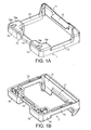
- a component 7 for use in apparatus embodying the first aspect of the present invention comprises a first portion 71 and a second portion 72. Respective ends of the first and second portions are connected together by means of two elongate members 73.
- the first portion 71 is shaped so as to function as a sidepost insulator, having a substantially upright bearing face 78 which receives lateral loads from the rail and transmits them to an adjacent rail clip anchoring device 1 (see Figure 3 ) and a shelf 77 which overlies part of the anchoring device 1.
- the second portion 72 comprises two spaced-apart clip seat regions 75, joined together by an elongate member 74.
- the clip seat regions 75 have respective L-shaped clip receiving surfaces 75a.
- the rear edge of each surface 75a is provided with a recess 75b shaped to ease installation of the clip.
- the elongate members 73, 74 and clip seat regions 75 are substantially hollow structures, having strengthening ribs as required.
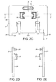
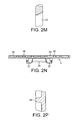
- the sealing plate 2 has a first major face 20 which is uppermost when the plate 2 is in use on the top of a sleeper and a second major face 21 opposite to the first.
- the sealing plate 2 is substantially rectangular in outline, having a cut-out portion along one side 22, defining ears 23 which ensure a seal at the corners of a shoulder 1 located above the plate 2 within the cut-out 22.
- the cut-out 22 has a bevelled edge 22a which mates with a corresponding bevelled edge on a rear face 15 of the shoulder 1.
- the cut-out 22 also has recesses 24 for receiving twin stems of the shoulder 1 (see Figure 3 ).
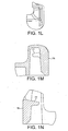
- the anchoring device 1 shown in Figure 3 comprises a head 1A from the underside of which downwardly project two stems 1B for embedding in the concrete sleeper during its manufacture.
- a Y-shaped stem may be used.
- the head 1A of the anchoring device 1 comprises two spaced-part walls 10, connected together at one end of the head 1A, at the bottom of the walls 10, by a connection portion 14.
- the top surface of the connection portion 14 is downwardly inclined and forms a ramp 140, while the front surface of the connection portion 14 forms the front face 12 of the shoulder 1.
- the end of the walls 10 at the front end of the head 1A are connected to the front face 12 of the shoulder by curved portions 13.
- the walls 10 extend outwardly at their tops to provide respective clip-engaging surfaces 11 provided with a clip-engaging projection 110, which projects downwardly.
- the clip-engaging sufaces 11 are inclined downwardly from the rear of the shoulder 1 to the front of the shoulder 1, for deflecting the leg of a railway rail fastening clip.
- the front face 12 of the shoulder 1 is provided with projections 120 for engaging with the sleeper mould so as to set the shoulder at the correct height in the mould before the concrete is introduced.
- a single shelf could be provided instead of the two projections 120.
- the shoulder 1 has a rear face 15 opposite to the front face 12.
- the major face 20 of the plate 2 is formed with upstanding tabs 27 which are provided for cooperating with respective features 127 on the underside of the shoulder 1 to retain the plate 2 on the shoulder 1 (and vice versa) before the plate 2 and shoulder 1 have been set into the concrete of the sleeper.
- Apertures 26 are also provided in the major face of the plate 2 to allow formation of the underside of tabs 27 during manufacture of the sealing plate 2.
- the shoulder 1 is held in place and positioned in the mould by means of a mechanism which pulls on the head 1A that protrudes through the bottom of the mould.
- the projections 120 on the shoulder 1 serve to reduce the amount of this pulling force which is applied to the sealing plate, which might otherwise distort.
- the first major face 20 of the plate 2 is also formed with an elongate upstand 25 along part of the rear edge of the plate 2 which assists in retaining the component 7, the elongate member 74 of the component 7 being positioned between the upstand 25 and the tabs 27 when the component is in use.
- the second major face 21 of the plate 2, which forms the underside of the plate, is formed with a plurality of intersecting ribs 28 which define numerous rebates 29.
- these rebates 29 are filled with concrete, providing additional strength to the plate 2, and thereby reducing the amount of material, and hence cost, required to make the plate 2.
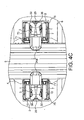
- the railway rail fastening assembly of Figures 4A to 4C for fastening a railway rail 5, comprises a shoulder 1 as described with reference to Fig. 3 , a rail fastening clip 3, a component 7 as described with reference to Fig. 1 , a sealing plate 2 as described with reference to Fig. 2 and a rail pad 4.
- a shoulder 1 as described with reference to Fig. 3
- a rail fastening clip 3 as described with reference to Fig. 1
- a sealing plate 2 as described with reference to Fig. 2
- a rail pad 4 a rail pad
- the clip 3 may be driven into the shoulder 1 by introducing the chamfered free ends of clip legs 31, 37 into the gaps between the top surfaces 75a of the clip seat regions 75 on the component 7 and the clip-engaging surfaces 11 on the outer surface of the walls 10 of the shoulder 1, and inserting a toe portion of the clip 3, bearing a toe insulator 34a, into the space between the inner surfaces of the walls 10 of the shoulder 1, such that the toe of the clip 3, through the toe insulator 34a, bears on the ramp 140 of the shoulder 1.
- This position is known as the "pre-assembly" or "parked” position, in which the clip does not bear on the rail 5, but overlies shelf 77 of component 7.
- Interlocking features on the toe insulator 34a and ramp 140 prevent the clip 1 "backing off” out of the shoulder 1.
- Downwardly-facing parts of the legs 31, 37 rest on the top surfaces 75a of the clip seat regions 75.
- the clip 3 can be driven from the pre-assembly position (first operative position) into a second operative position in which the toe portion of the clip 3 bears on the foot of the rail 5, the projections 110 on the walls 10 engage detents in the legs 31, 37 of the clip 3 and second and sixth portions 32, 36 (heel portions) of the clip 3 bear on the top surfaces 75a of the clip seat regions 75.
- the clip 3 overlies the shelf 77 of the side post insulator portion of the component 7. The clip can be withdrawn from this position back into the pre-assembly position, if required in order to remove or work on the rail.
- the toe of the clip 3 is driven upwards by the ramp 140 in the centre of the shoulder 1, and the legs 31, 37 are driven down, thereby spreading the clip apart. This makes it possible to make the assembly a little lower than would otherwise be possible.
Priority Applications (2)
| Application Number | Priority Date | Filing Date | Title |
|---|---|---|---|
| SI200731517T SI2176464T1 (sl) | 2007-07-04 | 2007-07-04 | Deli sklopa za pritrditev tirnice |
| PL07733453T PL2176464T3 (pl) | 2007-07-04 | 2007-07-04 | Elementy zespołu mocującego szynę |
Applications Claiming Priority (1)
| Application Number | Priority Date | Filing Date | Title |
|---|---|---|---|
| PCT/GB2007/002488 WO2009004274A1 (en) | 2007-07-04 | 2007-07-04 | Components for rail fastening assembl |
Publications (2)
| Publication Number | Publication Date |
|---|---|
| EP2176464A1 EP2176464A1 (en) | 2010-04-21 |
| EP2176464B1 true EP2176464B1 (en) | 2014-09-10 |
Family
ID=39201860
Family Applications (1)
| Application Number | Title | Priority Date | Filing Date |
|---|---|---|---|
| EP07733453.0A Active EP2176464B1 (en) | 2007-07-04 | 2007-07-04 | Components for rail fastening assembly |
Country Status (19)
| Country | Link |
|---|---|
| US (2) | US8286891B2 (ko) |
| EP (1) | EP2176464B1 (ko) |
| JP (1) | JP5227400B2 (ko) |
| KR (1) | KR101516940B1 (ko) |
| CN (1) | CN101688375B (ko) |
| AU (1) | AU2007355836B2 (ko) |
| BR (1) | BRPI0721678B1 (ko) |
| CA (1) | CA2691405C (ko) |
| DK (1) | DK2176464T3 (ko) |
| EG (1) | EG26323A (ko) |
| ES (1) | ES2514493T3 (ko) |
| MY (1) | MY151292A (ko) |
| NO (1) | NO340439B1 (ko) |
| NZ (2) | NZ581930A (ko) |
| PL (1) | PL2176464T3 (ko) |
| PT (1) | PT2176464E (ko) |
| SI (1) | SI2176464T1 (ko) |
| UA (1) | UA104573C2 (ko) |
| WO (1) | WO2009004274A1 (ko) |
Cited By (2)
| Publication number | Priority date | Publication date | Assignee | Title |
|---|---|---|---|---|
| RU190764U1 (ru) * | 2019-03-15 | 2019-07-11 | Дмитрий Евгеньевич Соловьёв | Изолирующая плита анкера рельсового скрепления |
| RU190762U1 (ru) * | 2019-03-15 | 2019-07-11 | Дмитрий Евгеньевич Соловьёв | Анкер рельсового скрепления, встраиваемый в железобетонную шпалу |
Families Citing this family (14)
| Publication number | Priority date | Publication date | Assignee | Title |
|---|---|---|---|---|
| GB2435285A (en) * | 2006-02-21 | 2007-08-22 | Pandrol Ltd | Fastening railway rails |
| DE202009004399U1 (de) * | 2009-02-11 | 2009-06-25 | Vossloh-Werke Gmbh | Führungsplatte für ein System zum Befestigen einer Schiene auf einem Untergrund und ein eine solche Führungsplatte umfassendes System |
| GB2494613A (en) | 2011-07-12 | 2013-03-20 | Pandrol Ltd | Railway rail fastening assembly anchoring device and associated component |
| DE102012100440A1 (de) * | 2012-01-19 | 2013-07-25 | Vossloh-Werke Gmbh | Plattenelement zum Führen einer Schiene und Verfahren zu seiner Herstellung |
| GB2500408B (en) * | 2012-03-21 | 2015-10-07 | Pandrol Ltd | Apparatus for use in concrete sleeper manufacture |
| PT2672007E (pt) * | 2012-06-04 | 2015-11-26 | Vossloh Werke Gmbh | Placa de guia para a fixação de carris para veículos ferroviários |
| JP6291496B2 (ja) * | 2012-08-31 | 2018-03-14 | パンドロール オーストラリア ピーティーワイ リミテッドPandrol Australia Pty Ltd | レール留めクリップのための固定デバイス |
| US9228297B2 (en) | 2012-11-28 | 2016-01-05 | Pandrol Limited | Rail support assembly with improved shoulder |
| GB2511740A (en) * | 2013-03-11 | 2014-09-17 | Pandrol Ltd | Railway Rail Baseplate Apparatus |
| GB201414595D0 (en) * | 2014-08-18 | 2014-10-01 | Pandrol Ltd | Railway Rail Side post Insulators and Railway Rail Clip Anchoring Device For use Therewith |
| GB2536692A (en) * | 2015-03-26 | 2016-09-28 | Pandrol Ltd | Vertical and lateral adjustment in a railway rail fastening assembly |
| NL2014640B1 (en) * | 2015-04-14 | 2016-12-20 | Movares Nederland Bv | Railway. |
| GB2572798B (en) * | 2018-04-11 | 2022-03-09 | Pandrol Ltd | An anchoring device for a railway rail fastening assembly |
| RU190775U1 (ru) * | 2018-12-28 | 2019-07-11 | Дмитрий Евгеньевич Соловьёв | Узел рельсового скрепления |
Family Cites Families (26)
| Publication number | Priority date | Publication date | Assignee | Title |
|---|---|---|---|---|
| US1224607A (en) * | 1916-08-07 | 1917-05-01 | James F Craven | Spike and tie-plate. |
| US1949363A (en) * | 1932-01-15 | 1934-02-27 | E H Bell | Railway tie plate |
| US2110894A (en) * | 1934-08-18 | 1938-03-15 | Resilient Products Corp | Tie plate arrangement for railroads |
| US2257923A (en) * | 1939-12-11 | 1941-10-07 | Verplanck Philip | Tie plate and rail support |
| US3544006A (en) * | 1969-01-22 | 1970-12-01 | Koppers Co Inc | Nonmetallic tie place |
| US3883072A (en) * | 1974-04-05 | 1975-05-13 | Portec Inc | Rail anchor |
| US3870231A (en) * | 1974-07-17 | 1975-03-11 | Tetsudo Kizai Kogyo Co Ltd | Rail fastening device |
| IN153328B (ko) | 1979-03-13 | 1984-06-30 | Rajaram Bojji | |
| GB2105389A (en) | 1981-08-27 | 1983-03-23 | Portec Inc | Insulated fastening for railway rails |
| ZA849298B (en) * | 1983-12-21 | 1985-07-31 | Mckay Ralph Ltd | Rail clip support |
| EP0194550B1 (de) * | 1985-03-15 | 1989-09-06 | Vossloh-Werke GmbH | Befestigungsklammer und Befestigungsanordnung für Eisenbahnschienen |
| FR2618463A1 (fr) * | 1987-07-20 | 1989-01-27 | Mounier Alain | Dispositif de fixation notamment des rails de roulement |
| IN185922B (ko) | 1991-12-18 | 2001-05-19 | Pandrol Ltd | |
| GB9415981D0 (en) * | 1994-08-08 | 1994-09-28 | Pandrol Ltd | Elastic rail clamp |
| US5865370A (en) * | 1997-06-06 | 1999-02-02 | Sonneville International Corporation | Rail fastening system for fastening a rail to a rail support and assembly including such rail fastening system coupled to the rail support |
| JP4189533B2 (ja) * | 1999-08-05 | 2008-12-03 | 日本発条株式会社 | 弾性レール締結装置 |
| TW509742B (en) * | 1999-11-24 | 2002-11-11 | Pandrol Ltd | Railway baseplate assembly |
| CA2303051A1 (en) | 2000-03-29 | 2001-09-29 | Jude Igwemezie | Rail insulator |
| WO2001096144A1 (en) * | 2000-06-12 | 2001-12-20 | Southco, Inc. | Tie-down hoop |
| US6367704B1 (en) * | 2000-06-28 | 2002-04-09 | Airboss Railway Products, Inc. | Rail fastening system constructed to allow pre-assembly of a rail clip and shoulder |
| DE10052534A1 (de) * | 2000-10-23 | 2002-04-25 | Hilti Ag | Schienenanbinder |
| JP3872983B2 (ja) * | 2001-12-06 | 2007-01-24 | 東日本旅客鉄道株式会社 | 分岐用ポイント |
| US6786459B2 (en) * | 2002-11-04 | 2004-09-07 | Ksa Limited Partnership | Concrete railroad tie turnout assembly |
| CN1560363A (zh) * | 2004-03-08 | 2005-01-05 | 沙同庆 | 防盗型铁路轨道固轨器 |
| JP4663736B2 (ja) * | 2004-12-29 | 2011-04-06 | コリア レイルロード リサーチ インスティテュート | レールを枕木に固定する弾性装置 |
| GB2435285A (en) | 2006-02-21 | 2007-08-22 | Pandrol Ltd | Fastening railway rails |
-
2007
- 2007-07-04 BR BRPI0721678-5A patent/BRPI0721678B1/pt active IP Right Grant
- 2007-07-04 CN CN2007800536303A patent/CN101688375B/zh active Active
- 2007-07-04 ES ES07733453.0T patent/ES2514493T3/es active Active
- 2007-07-04 CA CA2691405A patent/CA2691405C/en active Active
- 2007-07-04 DK DK07733453.0T patent/DK2176464T3/en active
- 2007-07-04 EP EP07733453.0A patent/EP2176464B1/en active Active
- 2007-07-04 WO PCT/GB2007/002488 patent/WO2009004274A1/en active Application Filing
- 2007-07-04 AU AU2007355836A patent/AU2007355836B2/en active Active
- 2007-07-04 NZ NZ581930A patent/NZ581930A/xx not_active IP Right Cessation
- 2007-07-04 KR KR1020107002595A patent/KR101516940B1/ko active IP Right Grant
- 2007-07-04 US US12/665,683 patent/US8286891B2/en active Active
- 2007-07-04 JP JP2010514087A patent/JP5227400B2/ja active Active
- 2007-07-04 NZ NZ602079A patent/NZ602079A/xx not_active IP Right Cessation
- 2007-07-04 PL PL07733453T patent/PL2176464T3/pl unknown
- 2007-07-04 UA UAA201000815A patent/UA104573C2/ru unknown
- 2007-07-04 PT PT77334530T patent/PT2176464E/pt unknown
- 2007-07-04 MY MYPI20120083 patent/MY151292A/en unknown
- 2007-07-04 SI SI200731517T patent/SI2176464T1/sl unknown
-
2010
- 2010-01-03 EG EG2010010001A patent/EG26323A/en active
- 2010-02-01 NO NO20100150A patent/NO340439B1/no unknown
-
2012
- 2012-04-03 US US13/438,529 patent/US20120187203A1/en not_active Abandoned
Cited By (2)
| Publication number | Priority date | Publication date | Assignee | Title |
|---|---|---|---|---|
| RU190764U1 (ru) * | 2019-03-15 | 2019-07-11 | Дмитрий Евгеньевич Соловьёв | Изолирующая плита анкера рельсового скрепления |
| RU190762U1 (ru) * | 2019-03-15 | 2019-07-11 | Дмитрий Евгеньевич Соловьёв | Анкер рельсового скрепления, встраиваемый в железобетонную шпалу |
Also Published As
| Publication number | Publication date |
|---|---|
| CA2691405C (en) | 2015-02-24 |
| WO2009004274A1 (en) | 2009-01-08 |
| EP2176464A1 (en) | 2010-04-21 |
| KR20100044821A (ko) | 2010-04-30 |
| BRPI0721678A2 (pt) | 2014-02-25 |
| AU2007355836B2 (en) | 2014-04-03 |
| NO340439B1 (no) | 2017-04-24 |
| UA104573C2 (ru) | 2014-02-25 |
| MY151292A (en) | 2014-04-30 |
| SI2176464T1 (sl) | 2014-10-30 |
| US20100181386A1 (en) | 2010-07-22 |
| NZ602079A (en) | 2013-10-25 |
| CN101688375A (zh) | 2010-03-31 |
| BRPI0721678B1 (pt) | 2018-07-03 |
| CN101688375B (zh) | 2012-07-11 |
| PT2176464E (pt) | 2014-09-18 |
| JP5227400B2 (ja) | 2013-07-03 |
| US20120187203A1 (en) | 2012-07-26 |
| ES2514493T3 (es) | 2014-10-28 |
| NZ581930A (en) | 2012-10-26 |
| NO20100150L (no) | 2010-03-23 |
| CA2691405A1 (en) | 2009-01-08 |
| AU2007355836A1 (en) | 2009-01-08 |
| EG26323A (en) | 2013-08-06 |
| PL2176464T3 (pl) | 2015-03-31 |
| DK2176464T3 (en) | 2014-12-15 |
| KR101516940B1 (ko) | 2015-05-04 |
| JP2010531940A (ja) | 2010-09-30 |
| US8286891B2 (en) | 2012-10-16 |
Similar Documents
| Publication | Publication Date | Title |
|---|---|---|
| EP2176464B1 (en) | Components for rail fastening assembly | |
| EP1987201B1 (en) | Railway rail pad | |
| RU2436885C2 (ru) | Детали узла скрепления рельса | |
| GB2450731A (en) | Component and sealing plate for rail fastening assembly | |
| WO2014140530A1 (en) | Railway rail baseplate apparatus | |
| GB2481338A (en) | Sealing plate for use with rail clip anchoring device |
Legal Events
| Date | Code | Title | Description |
|---|---|---|---|
| PUAI | Public reference made under article 153(3) epc to a published international application that has entered the european phase |
Free format text: ORIGINAL CODE: 0009012 |
|
| 17P | Request for examination filed |
Effective date: 20100201 |
|
| AK | Designated contracting states |
Kind code of ref document: A1 Designated state(s): AT BE BG CH CY CZ DE DK EE ES FI FR GB GR HU IE IS IT LI LT LU LV MC MT NL PL PT RO SE SI SK TR |
|
| AX | Request for extension of the european patent |
Extension state: AL BA HR MK RS |
|
| DAX | Request for extension of the european patent (deleted) | ||
| 17Q | First examination report despatched |
Effective date: 20130701 |
|
| GRAP | Despatch of communication of intention to grant a patent |
Free format text: ORIGINAL CODE: EPIDOSNIGR1 |
|
| INTG | Intention to grant announced |
Effective date: 20131220 |
|
| RIN1 | Information on inventor provided before grant (corrected) |
Inventor name: COX, STEPHEN, JOHN Inventor name: HAMILTON, ROBERT, JOHN |
|
| GRAS | Grant fee paid |
Free format text: ORIGINAL CODE: EPIDOSNIGR3 |
|
| RBV | Designated contracting states (corrected) |
Designated state(s): AT BE BG CH CY CZ DE DK EE ES FI FR GR HU IE IS IT LI LT LU LV MC MT NL PL PT RO SE SI SK TR |
|
| RIN1 | Information on inventor provided before grant (corrected) |
Inventor name: HAMILTON, ROBERT, JOHN Inventor name: COX, STEPHEN, JOHN |
|
| GRAA | (expected) grant |
Free format text: ORIGINAL CODE: 0009210 |
|
| AK | Designated contracting states |
Kind code of ref document: B1 Designated state(s): AT BE BG CH CY CZ DE DK EE ES FI FR GR HU IE IS IT LI LT LU LV MC MT NL PL PT RO SE SI SK TR |
|
| REG | Reference to a national code |
Ref country code: CH Ref legal event code: EP Ref country code: CH Ref legal event code: NV Representative=s name: DR. LUSUARDI AG, CH |
|
| REG | Reference to a national code |
Ref country code: PT Ref legal event code: SC4A Free format text: AVAILABILITY OF NATIONAL TRANSLATION Effective date: 20140911 |
|
| REG | Reference to a national code |
Ref country code: IE Ref legal event code: FG4D |
|
| REG | Reference to a national code |
Ref country code: AT Ref legal event code: REF Ref document number: 686769 Country of ref document: AT Kind code of ref document: T Effective date: 20141015 |
|
| REG | Reference to a national code |
Ref country code: DE Ref legal event code: R096 Ref document number: 602007038489 Country of ref document: DE Effective date: 20141016 |
|
| REG | Reference to a national code |
Ref country code: ES Ref legal event code: FG2A Ref document number: 2514493 Country of ref document: ES Kind code of ref document: T3 Effective date: 20141028 |
|
| REG | Reference to a national code |
Ref country code: NL Ref legal event code: T3 |
|
| REG | Reference to a national code |
Ref country code: GR Ref legal event code: EP Ref document number: 20140401925 Country of ref document: GR Effective date: 20141017 |
|
| REG | Reference to a national code |
Ref country code: RO Ref legal event code: EPE |
|
| REG | Reference to a national code |
Ref country code: DK Ref legal event code: T3 Effective date: 20141211 |
|
| REG | Reference to a national code |
Ref country code: SE Ref legal event code: TRGR |
|
| REG | Reference to a national code |
Ref country code: EE Ref legal event code: FG4A Ref document number: E009945 Country of ref document: EE Effective date: 20141125 |
|
| PG25 | Lapsed in a contracting state [announced via postgrant information from national office to epo] |
Ref country code: CY Free format text: LAPSE BECAUSE OF FAILURE TO SUBMIT A TRANSLATION OF THE DESCRIPTION OR TO PAY THE FEE WITHIN THE PRESCRIBED TIME-LIMIT Effective date: 20140910 |
|
| REG | Reference to a national code |
Ref country code: SK Ref legal event code: T3 Ref document number: E 17723 Country of ref document: SK |
|
| REG | Reference to a national code |
Ref country code: PL Ref legal event code: T3 |
|
| PG25 | Lapsed in a contracting state [announced via postgrant information from national office to epo] |
Ref country code: IS Free format text: LAPSE BECAUSE OF FAILURE TO SUBMIT A TRANSLATION OF THE DESCRIPTION OR TO PAY THE FEE WITHIN THE PRESCRIBED TIME-LIMIT Effective date: 20150110 |
|
| REG | Reference to a national code |
Ref country code: DE Ref legal event code: R097 Ref document number: 602007038489 Country of ref document: DE |
|
| PLBE | No opposition filed within time limit |
Free format text: ORIGINAL CODE: 0009261 |
|
| STAA | Information on the status of an ep patent application or granted ep patent |
Free format text: STATUS: NO OPPOSITION FILED WITHIN TIME LIMIT |
|
| REG | Reference to a national code |
Ref country code: HU Ref legal event code: AG4A Ref document number: E023251 Country of ref document: HU |
|
| 26N | No opposition filed |
Effective date: 20150611 |
|
| PG25 | Lapsed in a contracting state [announced via postgrant information from national office to epo] |
Ref country code: MC Free format text: LAPSE BECAUSE OF FAILURE TO SUBMIT A TRANSLATION OF THE DESCRIPTION OR TO PAY THE FEE WITHIN THE PRESCRIBED TIME-LIMIT Effective date: 20140910 |
|
| PG25 | Lapsed in a contracting state [announced via postgrant information from national office to epo] |
Ref country code: LU Free format text: LAPSE BECAUSE OF FAILURE TO SUBMIT A TRANSLATION OF THE DESCRIPTION OR TO PAY THE FEE WITHIN THE PRESCRIBED TIME-LIMIT Effective date: 20150704 |
|
| REG | Reference to a national code |
Ref country code: IE Ref legal event code: MM4A |
|
| REG | Reference to a national code |
Ref country code: FR Ref legal event code: PLFP Year of fee payment: 10 |
|
| PG25 | Lapsed in a contracting state [announced via postgrant information from national office to epo] |
Ref country code: IE Free format text: LAPSE BECAUSE OF NON-PAYMENT OF DUE FEES Effective date: 20150704 |
|
| PG25 | Lapsed in a contracting state [announced via postgrant information from national office to epo] |
Ref country code: MT Free format text: LAPSE BECAUSE OF FAILURE TO SUBMIT A TRANSLATION OF THE DESCRIPTION OR TO PAY THE FEE WITHIN THE PRESCRIBED TIME-LIMIT Effective date: 20140910 |
|
| REG | Reference to a national code |
Ref country code: FR Ref legal event code: PLFP Year of fee payment: 11 |
|
| REG | Reference to a national code |
Ref country code: FR Ref legal event code: PLFP Year of fee payment: 12 |
|
| REG | Reference to a national code |
Ref country code: DE Ref legal event code: R082 Ref document number: 602007038489 Country of ref document: DE Representative=s name: HL KEMPNER PATENTANWAELTE, SOLICITORS (ENGLAND, DE Ref country code: DE Ref legal event code: R082 Ref document number: 602007038489 Country of ref document: DE Representative=s name: HL KEMPNER PATENTANWALT, RECHTSANWALT, SOLICIT, DE |
|
| PGFP | Annual fee paid to national office [announced via postgrant information from national office to epo] |
Ref country code: PT Payment date: 20210617 Year of fee payment: 15 Ref country code: SK Payment date: 20210622 Year of fee payment: 15 |
|
| PGFP | Annual fee paid to national office [announced via postgrant information from national office to epo] |
Ref country code: NL Payment date: 20210721 Year of fee payment: 15 |
|
| PGFP | Annual fee paid to national office [announced via postgrant information from national office to epo] |
Ref country code: IT Payment date: 20210723 Year of fee payment: 15 Ref country code: AT Payment date: 20210707 Year of fee payment: 15 Ref country code: FI Payment date: 20210707 Year of fee payment: 15 |
|
| PGFP | Annual fee paid to national office [announced via postgrant information from national office to epo] |
Ref country code: ES Payment date: 20210817 Year of fee payment: 15 Ref country code: GR Payment date: 20210726 Year of fee payment: 15 |
|
| REG | Reference to a national code |
Ref country code: SK Ref legal event code: MM4A Ref document number: E 17723 Country of ref document: SK Effective date: 20220704 |
|
| REG | Reference to a national code |
Ref country code: NL Ref legal event code: MM Effective date: 20220801 |
|
| REG | Reference to a national code |
Ref country code: AT Ref legal event code: MM01 Ref document number: 686769 Country of ref document: AT Kind code of ref document: T Effective date: 20220704 |
|
| PG25 | Lapsed in a contracting state [announced via postgrant information from national office to epo] |
Ref country code: PT Free format text: LAPSE BECAUSE OF NON-PAYMENT OF DUE FEES Effective date: 20230104 Ref country code: FI Free format text: LAPSE BECAUSE OF NON-PAYMENT OF DUE FEES Effective date: 20220704 Ref country code: AT Free format text: LAPSE BECAUSE OF NON-PAYMENT OF DUE FEES Effective date: 20220704 |
|
| PG25 | Lapsed in a contracting state [announced via postgrant information from national office to epo] |
Ref country code: SK Free format text: LAPSE BECAUSE OF NON-PAYMENT OF DUE FEES Effective date: 20220704 Ref country code: GR Free format text: LAPSE BECAUSE OF NON-PAYMENT OF DUE FEES Effective date: 20230209 |
|
| P01 | Opt-out of the competence of the unified patent court (upc) registered |
Effective date: 20230330 |
|
| PG25 | Lapsed in a contracting state [announced via postgrant information from national office to epo] |
Ref country code: NL Free format text: LAPSE BECAUSE OF NON-PAYMENT OF DUE FEES Effective date: 20220801 |
|
| PG25 | Lapsed in a contracting state [announced via postgrant information from national office to epo] |
Ref country code: IT Free format text: LAPSE BECAUSE OF NON-PAYMENT OF DUE FEES Effective date: 20220704 |
|
| PGFP | Annual fee paid to national office [announced via postgrant information from national office to epo] |
Ref country code: RO Payment date: 20230606 Year of fee payment: 17 Ref country code: LT Payment date: 20230605 Year of fee payment: 17 |
|
| REG | Reference to a national code |
Ref country code: ES Ref legal event code: FD2A Effective date: 20230825 |
|
| PGFP | Annual fee paid to national office [announced via postgrant information from national office to epo] |
Ref country code: TR Payment date: 20230616 Year of fee payment: 17 Ref country code: PL Payment date: 20230620 Year of fee payment: 17 |
|
| PG25 | Lapsed in a contracting state [announced via postgrant information from national office to epo] |
Ref country code: ES Free format text: LAPSE BECAUSE OF NON-PAYMENT OF DUE FEES Effective date: 20220705 |
|
| PGFP | Annual fee paid to national office [announced via postgrant information from national office to epo] |
Ref country code: EE Payment date: 20230724 Year of fee payment: 17 Ref country code: CZ Payment date: 20230703 Year of fee payment: 17 Ref country code: CH Payment date: 20230802 Year of fee payment: 17 Ref country code: BG Payment date: 20230725 Year of fee payment: 17 |
|
| PGFP | Annual fee paid to national office [announced via postgrant information from national office to epo] |
Ref country code: SI Payment date: 20230619 Year of fee payment: 17 Ref country code: SE Payment date: 20230724 Year of fee payment: 17 Ref country code: HU Payment date: 20230609 Year of fee payment: 17 Ref country code: FR Payment date: 20230710 Year of fee payment: 17 Ref country code: DK Payment date: 20230725 Year of fee payment: 17 Ref country code: DE Payment date: 20230724 Year of fee payment: 17 Ref country code: BE Payment date: 20230720 Year of fee payment: 17 |
|
| PGFP | Annual fee paid to national office [announced via postgrant information from national office to epo] |
Ref country code: LV Payment date: 20230721 Year of fee payment: 17 |