EP2175705A1 - Verfahren und Gerät zum Zusammenbau einer Pastille auf einem Substrat durch Zufuhr von Lötmaterial - Google Patents
Verfahren und Gerät zum Zusammenbau einer Pastille auf einem Substrat durch Zufuhr von Lötmaterial Download PDFInfo
- Publication number
- EP2175705A1 EP2175705A1 EP09172640A EP09172640A EP2175705A1 EP 2175705 A1 EP2175705 A1 EP 2175705A1 EP 09172640 A EP09172640 A EP 09172640A EP 09172640 A EP09172640 A EP 09172640A EP 2175705 A1 EP2175705 A1 EP 2175705A1
- Authority
- EP
- European Patent Office
- Prior art keywords
- mass
- substrate
- variation
- heating
- vertical
- Prior art date
- Legal status (The legal status is an assumption and is not a legal conclusion. Google has not performed a legal analysis and makes no representation as to the accuracy of the status listed.)
- Granted
Links
Images
Classifications
-
- H—ELECTRICITY
- H05—ELECTRIC TECHNIQUES NOT OTHERWISE PROVIDED FOR
- H05K—PRINTED CIRCUITS; CASINGS OR CONSTRUCTIONAL DETAILS OF ELECTRIC APPARATUS; MANUFACTURE OF ASSEMBLAGES OF ELECTRICAL COMPONENTS
- H05K3/00—Apparatus or processes for manufacturing printed circuits
- H05K3/30—Assembling printed circuits with electric components, e.g. with resistor
- H05K3/32—Assembling printed circuits with electric components, e.g. with resistor electrically connecting electric components or wires to printed circuits
- H05K3/34—Assembling printed circuits with electric components, e.g. with resistor electrically connecting electric components or wires to printed circuits by soldering
-
- B—PERFORMING OPERATIONS; TRANSPORTING
- B23—MACHINE TOOLS; METAL-WORKING NOT OTHERWISE PROVIDED FOR
- B23K—SOLDERING OR UNSOLDERING; WELDING; CLADDING OR PLATING BY SOLDERING OR WELDING; CUTTING BY APPLYING HEAT LOCALLY, e.g. FLAME CUTTING; WORKING BY LASER BEAM
- B23K1/00—Soldering, e.g. brazing, or unsoldering
- B23K1/005—Soldering by means of radiant energy
- B23K1/0056—Soldering by means of radiant energy soldering by means of beams, e.g. lasers, E.B.
-
- B—PERFORMING OPERATIONS; TRANSPORTING
- B23—MACHINE TOOLS; METAL-WORKING NOT OTHERWISE PROVIDED FOR
- B23K—SOLDERING OR UNSOLDERING; WELDING; CLADDING OR PLATING BY SOLDERING OR WELDING; CUTTING BY APPLYING HEAT LOCALLY, e.g. FLAME CUTTING; WORKING BY LASER BEAM
- B23K3/00—Tools, devices, or special appurtenances for soldering, e.g. brazing, or unsoldering, not specially adapted for particular methods
- B23K3/06—Solder feeding devices; Solder melting pans
- B23K3/0607—Solder feeding devices
-
- H—ELECTRICITY
- H05—ELECTRIC TECHNIQUES NOT OTHERWISE PROVIDED FOR
- H05K—PRINTED CIRCUITS; CASINGS OR CONSTRUCTIONAL DETAILS OF ELECTRIC APPARATUS; MANUFACTURE OF ASSEMBLAGES OF ELECTRICAL COMPONENTS
- H05K3/00—Apparatus or processes for manufacturing printed circuits
- H05K3/30—Assembling printed circuits with electric components, e.g. with resistor
- H05K3/32—Assembling printed circuits with electric components, e.g. with resistor electrically connecting electric components or wires to printed circuits
- H05K3/34—Assembling printed circuits with electric components, e.g. with resistor electrically connecting electric components or wires to printed circuits by soldering
- H05K3/341—Surface mounted components
-
- H10W72/0711—
-
- B—PERFORMING OPERATIONS; TRANSPORTING
- B23—MACHINE TOOLS; METAL-WORKING NOT OTHERWISE PROVIDED FOR
- B23K—SOLDERING OR UNSOLDERING; WELDING; CLADDING OR PLATING BY SOLDERING OR WELDING; CUTTING BY APPLYING HEAT LOCALLY, e.g. FLAME CUTTING; WORKING BY LASER BEAM
- B23K2101/00—Articles made by soldering, welding or cutting
- B23K2101/36—Electric or electronic devices
-
- H—ELECTRICITY
- H05—ELECTRIC TECHNIQUES NOT OTHERWISE PROVIDED FOR
- H05K—PRINTED CIRCUITS; CASINGS OR CONSTRUCTIONAL DETAILS OF ELECTRIC APPARATUS; MANUFACTURE OF ASSEMBLAGES OF ELECTRICAL COMPONENTS
- H05K2201/00—Indexing scheme relating to printed circuits covered by H05K1/00
- H05K2201/10—Details of components or other objects attached to or integrated in a printed circuit board
- H05K2201/10613—Details of electrical connections of non-printed components, e.g. special leads
- H05K2201/10954—Other details of electrical connections
- H05K2201/10969—Metallic case or integral heatsink of component electrically connected to a pad on PCB
-
- H—ELECTRICITY
- H05—ELECTRIC TECHNIQUES NOT OTHERWISE PROVIDED FOR
- H05K—PRINTED CIRCUITS; CASINGS OR CONSTRUCTIONAL DETAILS OF ELECTRIC APPARATUS; MANUFACTURE OF ASSEMBLAGES OF ELECTRICAL COMPONENTS
- H05K2203/00—Indexing scheme relating to apparatus or processes for manufacturing printed circuits covered by H05K3/00
- H05K2203/01—Tools for processing; Objects used during processing
- H05K2203/0195—Tool for a process not provided for in H05K3/00, e.g. tool for handling objects using suction, for deforming objects, for applying local pressure
-
- H—ELECTRICITY
- H05—ELECTRIC TECHNIQUES NOT OTHERWISE PROVIDED FOR
- H05K—PRINTED CIRCUITS; CASINGS OR CONSTRUCTIONAL DETAILS OF ELECTRIC APPARATUS; MANUFACTURE OF ASSEMBLAGES OF ELECTRICAL COMPONENTS
- H05K2203/00—Indexing scheme relating to apparatus or processes for manufacturing printed circuits covered by H05K3/00
- H05K2203/04—Soldering or other types of metallurgic bonding
- H05K2203/0415—Small preforms other than balls, e.g. discs, cylinders or pillars
-
- H—ELECTRICITY
- H05—ELECTRIC TECHNIQUES NOT OTHERWISE PROVIDED FOR
- H05K—PRINTED CIRCUITS; CASINGS OR CONSTRUCTIONAL DETAILS OF ELECTRIC APPARATUS; MANUFACTURE OF ASSEMBLAGES OF ELECTRICAL COMPONENTS
- H05K2203/00—Indexing scheme relating to apparatus or processes for manufacturing printed circuits covered by H05K3/00
- H05K2203/10—Using electric, magnetic and electromagnetic fields; Using laser light
- H05K2203/107—Using laser light
-
- H—ELECTRICITY
- H05—ELECTRIC TECHNIQUES NOT OTHERWISE PROVIDED FOR
- H05K—PRINTED CIRCUITS; CASINGS OR CONSTRUCTIONAL DETAILS OF ELECTRIC APPARATUS; MANUFACTURE OF ASSEMBLAGES OF ELECTRICAL COMPONENTS
- H05K2203/00—Indexing scheme relating to apparatus or processes for manufacturing printed circuits covered by H05K3/00
- H05K2203/16—Inspection; Monitoring; Aligning
- H05K2203/163—Monitoring a manufacturing process
-
- H—ELECTRICITY
- H05—ELECTRIC TECHNIQUES NOT OTHERWISE PROVIDED FOR
- H05K—PRINTED CIRCUITS; CASINGS OR CONSTRUCTIONAL DETAILS OF ELECTRIC APPARATUS; MANUFACTURE OF ASSEMBLAGES OF ELECTRICAL COMPONENTS
- H05K3/00—Apparatus or processes for manufacturing printed circuits
- H05K3/30—Assembling printed circuits with electric components, e.g. with resistor
- H05K3/32—Assembling printed circuits with electric components, e.g. with resistor electrically connecting electric components or wires to printed circuits
- H05K3/34—Assembling printed circuits with electric components, e.g. with resistor electrically connecting electric components or wires to printed circuits by soldering
- H05K3/3494—Heating methods for reflowing of solder
-
- Y—GENERAL TAGGING OF NEW TECHNOLOGICAL DEVELOPMENTS; GENERAL TAGGING OF CROSS-SECTIONAL TECHNOLOGIES SPANNING OVER SEVERAL SECTIONS OF THE IPC; TECHNICAL SUBJECTS COVERED BY FORMER USPC CROSS-REFERENCE ART COLLECTIONS [XRACs] AND DIGESTS
- Y02—TECHNOLOGIES OR APPLICATIONS FOR MITIGATION OR ADAPTATION AGAINST CLIMATE CHANGE
- Y02P—CLIMATE CHANGE MITIGATION TECHNOLOGIES IN THE PRODUCTION OR PROCESSING OF GOODS
- Y02P70/00—Climate change mitigation technologies in the production process for final industrial or consumer products
- Y02P70/50—Manufacturing or production processes characterised by the final manufactured product
-
- Y—GENERAL TAGGING OF NEW TECHNOLOGICAL DEVELOPMENTS; GENERAL TAGGING OF CROSS-SECTIONAL TECHNOLOGIES SPANNING OVER SEVERAL SECTIONS OF THE IPC; TECHNICAL SUBJECTS COVERED BY FORMER USPC CROSS-REFERENCE ART COLLECTIONS [XRACs] AND DIGESTS
- Y10—TECHNICAL SUBJECTS COVERED BY FORMER USPC
- Y10T—TECHNICAL SUBJECTS COVERED BY FORMER US CLASSIFICATION
- Y10T29/00—Metal working
- Y10T29/49—Method of mechanical manufacture
- Y10T29/49002—Electrical device making
- Y10T29/49117—Conductor or circuit manufacturing
- Y10T29/49124—On flat or curved insulated base, e.g., printed circuit, etc.
- Y10T29/4913—Assembling to base an electrical component, e.g., capacitor, etc.
- Y10T29/49144—Assembling to base an electrical component, e.g., capacitor, etc. by metal fusion
-
- Y—GENERAL TAGGING OF NEW TECHNOLOGICAL DEVELOPMENTS; GENERAL TAGGING OF CROSS-SECTIONAL TECHNOLOGIES SPANNING OVER SEVERAL SECTIONS OF THE IPC; TECHNICAL SUBJECTS COVERED BY FORMER USPC CROSS-REFERENCE ART COLLECTIONS [XRACs] AND DIGESTS
- Y10—TECHNICAL SUBJECTS COVERED BY FORMER USPC
- Y10T—TECHNICAL SUBJECTS COVERED BY FORMER US CLASSIFICATION
- Y10T29/00—Metal working
- Y10T29/53—Means to assemble or disassemble
- Y10T29/5313—Means to assemble electrical device
- Y10T29/53174—Means to fasten electrical component to wiring board, base, or substrate
- Y10T29/53178—Chip component
Definitions
- the present invention relates to the technical field of brazing a member on a substrate by providing a solder mass.
- the quality of the solder depends in particular on the wettability properties of the surface of the substrate ensuring good wetting, that is to say sufficient spreading, of the mass on the substrate. More specifically, the wettability of the surface is defined by a contact angle, also referred to as the wetting angle, formed between the tangent to the surface of the mass and the tangent to the surface of the substrate at a point of contact with the surface. mass and substrate.
- the heating of the mass is for example obtained by irranding the mass by a controlled continuous laser source so as to produce long pulses, for example longer than about two seconds.
- the propagation time of the heat through the substrate and the mass is no longer negligible compared to the duration of a laser pulse which corresponds to the heating time.
- the length of the period during which the mass is actually in its liquid state does not necessarily correspond to the heating time.
- the object of the invention is in particular to propose a method of assembling an element on a substrate by providing a brazing mass which makes it possible to control accurately the period of time during which the mass is in its liquid state to optimize its wetting on the substrate.
- the mass is a self-supporting mass, that is to say a mass independent of the element and the substrate, which can be reported on the cell separately from the element and the substrate.
- the mass liquefies and the intensity of the reaction force exerted by the mass on the element becomes less than the intensity of the force of gravity exerted by the element on the mass, which causes the element to move under the action of its gravity towards the substrate.
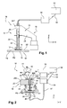
- the installation 10 allows to assemble an element 12 on a substrate 14 by providing a mass 16 forming solder.
- the element 12 is a conventional semiconductor chip.
- the mass 16 is a freestanding mass independent of the element 12 and the substrate 14 and is for example in the form of a solder paste or a thin ribbon cut into a disk or rectangle.
- the substrate 14 comprises in the example described a metal part PM, in particular copper, partially bordered by a part PS made of synthetic material forming a part of a protective case of the semiconductor chip 12 carried by the substrate 14.
- substrate 14 has first S1 and second S2 opposite sides.
- the mass 16 is intended to be carried by the second face S2 of the metal part PM of the substrate.
- the second face S2 is covered with a thin layer of nickel.
- the assembly installation 10 comprises an assembly device 18.
- This assembly device 18 comprises means 20 for moving the pellet 12 or the mass 16 in such a way that depositing it on the second face S2 of the substrate 14.
- These displacement means 20 comprise articulated means 22 for moving the pellet 12 or the mass 16 in a horizontal plane substantially parallel to the X and Y axes and in a vertical direction substantially parallel to an axis Z.
- the articulated means 22 comprise in this example, an arm 24 provided with a head 24T.
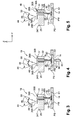
- This head 24T comprises a support 25 carrying a member 26 for gripping the pellet 12 or the mass 16.
- the member 26 is mounted free in translation on the support 25 parallel to a vertical translation axis, substantially parallel to the Y axis.
- the gripping member 26 is connected to the head 24T by means of a slide connection.
- the head 24T comprises a through hole 28 for guiding the member 26.
- the gripping member 26 has for example a general T shape comprising a first portion 26A forming the leg of the T and a second portion 26B forming the bar T.
- the first portion 26A has a general shape complementary to an inner wall 28I of the hole 28 thus allowing the gripping member 26 to slide inside the hole 28.
- the friction force generated during the translation of the member 26 inside hole 28 has a value less than ten grams / force.
- the device 18 comprises means 30 for limiting the travel in vertical translation of the member 26 and thus more precisely the pellet 12 intended to be carried by the member 26.
- the limiting means 30 comprise a first abutment member 30A formed on the support 25 and a second abutment member 30B formed by one end of the second portion 26B of the member 26, the abutment members 30A and 30B being adapted to engage one another; with the other when moving in the direction of the vertical axis Y of the gripping member 26 to limit the stroke of the latter.
- the first element 30A is formed by a shim 31 intended to extend on a surface 25S of the support 25 of the head 24T.
- the gripping member 26 is for example suction.
- the gripping member 26 comprises a suction duct 32 connected at one of its ends to suction means 34 comprising for example a vacuum pump.
- This suction duct 32 extends inside a hole passing through the gripping member 26 in its longitudinal direction, the other end of the duct 32 opening at one end of the gripping member 26 intended to come into contact with the pellet 12 during assembly on the substrate 14.
- the gripping member 26 can be secured to the head 24T by means of releasable connection means capable of adopting an active state in which the member 26 is connected to the head 24T integrally therewith and a state of rest in which the member 26 is free relative to the head 24T.
- the device 18 also comprises counterweight means (not shown) with respect to the gripping member 26.
- these counterweight means at least partially, preferably completely, oppose the weight of the gripping member 26.
- the residual weight corresponding to the sum of the weight of the gripping member 26 compensated at least partially by the counterweight means and the weight of the wafer 12 carried by the gripping member 26 must be slightly greater than the friction force generated during the translation of the member 26 inside the hole 28.
- the installation 10 comprises heating means 36 comprising, for example, a continuous and controlled laser source for producing pulses of predetermined duration, for example equal to two seconds, an optical fiber 37 for guiding a laser beam 40 emitted by the source and means 38 for focusing the laser beam 40 at a point 42 in line with the mass 16 forming solder.
- heating means 36 comprising, for example, a continuous and controlled laser source for producing pulses of predetermined duration, for example equal to two seconds, an optical fiber 37 for guiding a laser beam 40 emitted by the source and means 38 for focusing the laser beam 40 at a point 42 in line with the mass 16 forming solder.
- the device 18 also comprises means 44 for measuring the variation in vertical translation of the position of the pellet 12. These measuring means 44 are means for measuring the variation in vertical translation of the position of the gripping member 26 .
- the measuring means 44 comprise means 46 for transmitting an incident light beam intended to emit a beam 48 on a surface 26S of the gripping member 26 substantially perpendicular to the Y axis and means 50 for receiving a part of the reflected beam 48 by this surface 26S.
- the measuring means 44 comprise a laser triangulation displacement sensor.
- the transmission means 46 comprise an infrared laser source as well as means for focusing the incident beam 48 emitted by the laser source on the surface 26S.
- the reception means 50 preferably comprise a CCD cell. To measure the displacement of the member 26, the variation of the position of the point of impact of the reflected beam 48 on the CCD cell is measured, this variation being related to the variation of the position of the surface 26S of the member 26 .
- the surface 26S extends on the upper face of the second portion 26B of the member 26.
- These means 44 can measure with an accuracy of one micrometer the variation of the position of the member 26 along an axis perpendicular to the surface 26S of the member and operate at a high acquisition frequency (about five kHz).
- the displacement means 22 make it possible to position the member 26 with an accuracy of approximately one micrometer.
- the installation 10 further comprises means 52 for controlling the heating means 36 as a function of the variation of the position of the element 12 or 16.
- the device 18 comprises conventional communication means 54 (wired, infra-red, etc.) between the measuring means 44, the heating means 36 and the moving means 22.
- a vertical stack Y is formed which coincides substantially with the direction of gravity comprising, from top to bottom, the pellet 12, the mass 16 in a solid state and the substrate 14.
- the articulated arm 22 moves the gripping member 26 integral with the head 24T and the control means 52 activate the suction means 34 so that the mass 16 is grasped by suction by the member 26 then moved to the substrate 14 by the articulated arm 22.
- the displacement of the gripping member 26 is relatively precise because directly related to that of the articulated means 22.
- the suction means 34 Upon detection of the contact position of the mass 16 with the surface S2 of the substrate 14, the suction means 34 are deactivated so that the gripping member 26 releases the mass 16 on the substrate 14.
- the pellet 12 is placed on the mass 16 in the same way.
- the releasable connecting means of the head 24T are deactivated with the gripping member 26 so that the member 26 can move in translation freely in the hole 28 of the head 24T.
- the second portion 26B of the gripping member 26 is located above the wedge 31 and the distance along the vertical axis Y between the wedge 31 and the second portion 26B defines a maximum stroke of the member 26 in translation.
- the value of this race is chosen so as to allow a sufficiently accurate measurement of the variation of the height of the member 26 while preserving the quality of the solder. Indeed, a too large stroke value may cause the expulsion of the mass on the sides of the pellet and thus form a solder joint of reduced thickness under the pellet 12.
- this distance is equal to 2.5 micrometers and corresponds substantially to a variation in the height of the mass 16 when changing from its solid state to its liquid state relative to the substrate 14.
- a stroke of organ 26 equal to ten micrometers provides a relatively accurate measurement of the variation in height without the risk of causing the expulsion of the mass on the sides of the pellet 12, during displacement of the pellet 12 against the mass.
- the control means 52 control the start of the heating of the mass 16.
- the mass 16 is heated to a predetermined temperature for a predetermined duration corresponding for example to a duration of the laser pulse.
- the laser beam 40 is directed on the first face S1 of the substrate. More precisely, the laser beam 40 is directed at the right of mass 16 during a period of irradiation of substrate 14 by beam 40. This irradiation period corresponds substantially to the predetermined duration of heating of mass 16.
- the temperature of the mass 16 increases without its state changes.
- the mass 16 exerts a reaction force on the pellet 12 making it possible to substantially compensate the force of gravity exerted by the pellet 12 on the mass 16.
- the mass 16 moves from a solid state to a liquid state allowing it to spread on the substrate 14 as is visible on the figure 4 .
- the intensity of the reaction force exerted on the pellet 12 by the mass 16 in the liquid state decreases.
- the at least partial compensation of the weight of the member 26 by the counterweight means makes it possible to limit the pressure exerted by the pellet 12 on the liquid mass 16 during the heating step and thus to avoid the risks of creep of the mass on the sides of the pellet 12 and the compression of the pellet 12 directly on the substrate 14.
- the measuring means 44 detect the variation of the position of the gripping member 26, which makes it possible to deduce therefrom the variation of the position of the pellet 12.
- the descent along the Y axis of the pellet 12 stops when the mass 16 is entirely in its liquid state which occurs when the end of the second portion 26B of the member 26 abuts the member 26 against the shim 31 extending over the head 24T. The pellet 12 is then stabilized.
- the measuring means 44 then detect the stabilization of the vertical position of the pellet 12 subsequent to the lowering of the pellet 12 and send a signal to the control means 52 which trigger from the instant of this stabilization detection, a stopwatch to count the predetermined time.
- This predetermined duration is equal to about one second.
- control means 52 maintain the activation of the heating means 36 of the mass 16 for the predetermined duration counted from the stabilization of the position of the pellet 12.
- control means 52 stop the heating.
- the position of the pellet 12 does not vary as the mass 16 remains liquid after stopping the heating.
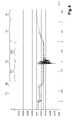
- the period during which mass 16 is in the state liquid corresponds to the period T3.
- This period T3 corresponds to the period during which the position of the pellet 12 is stabilized.
- the measuring means 44 detect the stabilization of the high Y position of the pellet 12, they send a signal to the control means 52 so that they control the stopping of the suction means 34. then release the lozenge 12.
- the wetting time of the mass 16 on the substrate can be determined with great accuracy by observing the variations of the position of the wafer 12.
- the duration of the period during which the mass 16 is in the liquid state has a controlled and programmable minimum value.
- the graph comprising the curve describing the principal phases determined above is recorded. With this curve, it is possible to determine an abnormal deviation from desired values of duration of each of the distinct periods identified.
Landscapes
- Engineering & Computer Science (AREA)
- Manufacturing & Machinery (AREA)
- Microelectronics & Electronic Packaging (AREA)
- Mechanical Engineering (AREA)
- Physics & Mathematics (AREA)
- Optics & Photonics (AREA)
- Electric Connection Of Electric Components To Printed Circuits (AREA)
- Computer Hardware Design (AREA)
- Power Engineering (AREA)
- Adornments (AREA)
- Die Bonding (AREA)
- Manufacturing Of Printed Wiring (AREA)
Priority Applications (1)
| Application Number | Priority Date | Filing Date | Title |
|---|---|---|---|
| PL09172640T PL2175705T3 (pl) | 2008-10-10 | 2009-10-09 | Sposób i urządzenie do montażu chipa na podłożu poprzez nasienie masy tworzącej lutowinę |
Applications Claiming Priority (1)
| Application Number | Priority Date | Filing Date | Title |
|---|---|---|---|
| FR0856876A FR2937216B1 (fr) | 2008-10-10 | 2008-10-10 | Procede et dispositif d'assemblage d'une pastille sur un substrat par apport d'une masse formant brasure. |
Publications (2)
| Publication Number | Publication Date |
|---|---|
| EP2175705A1 true EP2175705A1 (de) | 2010-04-14 |
| EP2175705B1 EP2175705B1 (de) | 2012-01-04 |
Family
ID=40384759
Family Applications (1)
| Application Number | Title | Priority Date | Filing Date |
|---|---|---|---|
| EP09172640A Not-in-force EP2175705B1 (de) | 2008-10-10 | 2009-10-09 | Verfahren und Gerät zum Zusammenbau einer Pastille auf einem Substrat durch Zufuhr von Lötmaterial |
Country Status (5)
| Country | Link |
|---|---|
| US (2) | US9167703B2 (de) |
| EP (1) | EP2175705B1 (de) |
| AT (1) | ATE540562T1 (de) |
| FR (1) | FR2937216B1 (de) |
| PL (1) | PL2175705T3 (de) |
Families Citing this family (1)
| Publication number | Priority date | Publication date | Assignee | Title |
|---|---|---|---|---|
| US9475151B1 (en) * | 2012-10-30 | 2016-10-25 | Western Digital (Fremont), Llc | Method and apparatus for attaching a laser diode and a slider in an energy assisted magnetic recording head |
Citations (2)
| Publication number | Priority date | Publication date | Assignee | Title |
|---|---|---|---|---|
| FR2003802A1 (de) * | 1968-03-13 | 1969-11-14 | Smits & Laubmeyer Zeva Elekt | |
| FR2905883A1 (fr) * | 2006-09-14 | 2008-03-21 | Valeo Electronique Sys Liaison | Procede de soudage d'un organe sur un support par apport de matiere et dispositif d'agencement de deux elements l'un sur l'autre |
Family Cites Families (6)
| Publication number | Priority date | Publication date | Assignee | Title |
|---|---|---|---|---|
| US3934073A (en) * | 1973-09-05 | 1976-01-20 | F Ardezzone | Miniature circuit connection and packaging techniques |
| DE19751352A1 (de) * | 1997-11-20 | 1999-05-27 | Leica Geosystems Ag | Verfahren zur Lötbefestigung miniaturisierter Bauteile für eine Grundplatte |
| JP3147845B2 (ja) * | 1998-02-13 | 2001-03-19 | 日本電気株式会社 | チップ部品接合装置および方法 |
| DE10042661B4 (de) * | 1999-09-10 | 2006-04-13 | Esec Trading S.A. | Verfahren und Vorrichtungen für die Montage von Halbleiterchips |
| CA2587245C (en) * | 2004-11-12 | 2013-12-31 | Rvsi Inspection Llc | Laser triangulation method for measurement of highly reflective solder balls |
| US20090289098A1 (en) * | 2005-12-06 | 2009-11-26 | Katsumi Terada | Chip Mounting Apparatus and Chip Mounting Method |
-
2008
- 2008-10-10 FR FR0856876A patent/FR2937216B1/fr not_active Expired - Fee Related
-
2009
- 2009-10-09 PL PL09172640T patent/PL2175705T3/pl unknown
- 2009-10-09 US US12/576,542 patent/US9167703B2/en not_active Expired - Fee Related
- 2009-10-09 EP EP09172640A patent/EP2175705B1/de not_active Not-in-force
- 2009-10-09 AT AT09172640T patent/ATE540562T1/de active
-
2014
- 2014-06-25 US US14/314,551 patent/US9706665B2/en not_active Expired - Fee Related
Patent Citations (2)
| Publication number | Priority date | Publication date | Assignee | Title |
|---|---|---|---|---|
| FR2003802A1 (de) * | 1968-03-13 | 1969-11-14 | Smits & Laubmeyer Zeva Elekt | |
| FR2905883A1 (fr) * | 2006-09-14 | 2008-03-21 | Valeo Electronique Sys Liaison | Procede de soudage d'un organe sur un support par apport de matiere et dispositif d'agencement de deux elements l'un sur l'autre |
Also Published As
| Publication number | Publication date |
|---|---|
| US20100139089A1 (en) | 2010-06-10 |
| US20140304984A1 (en) | 2014-10-16 |
| FR2937216A1 (fr) | 2010-04-16 |
| US9706665B2 (en) | 2017-07-11 |
| PL2175705T3 (pl) | 2012-05-31 |
| US9167703B2 (en) | 2015-10-20 |
| FR2937216B1 (fr) | 2010-12-31 |
| ATE540562T1 (de) | 2012-01-15 |
| EP2175705B1 (de) | 2012-01-04 |
Similar Documents
| Publication | Publication Date | Title |
|---|---|---|
| FR2659039A1 (fr) | Procede et appareil de surveillance optique du traitement des materiaux par laser. | |
| EP2064017A2 (de) | Verfahren zur haftung eines elements an einen träger mittels materialzugabe sowie vorrichtung zur anordnung zweier elemente übereinander | |
| EP0481876B1 (de) | Justierverfahren der optischen Achsen von einer Faser und von einem optoelektronischen Bauelement und die mit diesem Verfahren hergestellte Vorrichtung | |
| EP2368125A1 (de) | Einrichtung zum regeln eines drahtanemometers | |
| CA3094862A1 (fr) | Lingotiere de coulee continue de metaux, systeme et procede de detection de percee dans une installation de coulee continue de metaux | |
| EP2175705B1 (de) | Verfahren und Gerät zum Zusammenbau einer Pastille auf einem Substrat durch Zufuhr von Lötmaterial | |
| EP1477266A1 (de) | Laser Punktschweissverfahren und -vorrichtung zum wirksamen Prüfen der Schweissqualität | |
| WO1998026318A1 (fr) | Assemblage de composants optiques alignes optiquement et procede de fabrication de cet assemblage | |
| EP0112211A1 (de) | Verfahren zum Ausrichten eines optoelektronischen Gerätes | |
| FR3133549A1 (fr) | Procédé de fonctionnement d’un système de fusion laser sur lit de poudre | |
| EP1949055A1 (de) | Optische heterodyne-sampling-einrichtung | |
| EP1864743B1 (de) | Verbindung und Verfahren zur Verbindung eines Gegenstands und eines Trägers durch Löten | |
| FR2910621A1 (fr) | Procede et dispositif de controle de la qualite d'un cordon de soudure | |
| FR2627868A1 (fr) | Procede de couplage permanent d'une fibre optique a un composant, notamment a un laser semi-conducteur | |
| FR2690996A1 (fr) | Dispositif d'alignement optique entre un composant optoélectronique et un composant optique, et procédé d'alignement. | |
| EP2150972B1 (de) | Verfahren zur Montage eines elektronischen Moduls mit einem auf einem Träger durch Sintern einer leitenden pulverförmigen Masse montierten Bauelement | |
| EP2937723B1 (de) | Verfahren zur befestigung einer optischen faser mit einer halterung einer laserdiode | |
| EP2379459B1 (de) | Verfahren zur beschichtung eines laserkomponents und dazu gehörende vorrichtung | |
| EP4197672A1 (de) | Verfahren zur integration eines sensors in ein teil durch generative fertigung | |
| EP4367491A1 (de) | Verfahren zur bestimmung einer verformung eines bereichs eines durch generative fertigung erhaltenen teils | |
| EP1814687B1 (de) | Verfahren zum laserschweissen ohne materialzusatz und unter verwendung des verfahrens hergestellte elektrische vorrichtung | |
| WO2015189513A1 (fr) | Procédé de collage direct | |
| FR2746214A1 (fr) | Procede et machine d'hybridation par refusion | |
| FR3163009A1 (fr) | Procédé de soudage d’une membrane d’étanchéité adaptée pour une cuve et dispositif correspondant | |
| FR2954720A1 (fr) | Procede et dispositif de soudage laser et faisceau d'electrons en penetration totale |
Legal Events
| Date | Code | Title | Description |
|---|---|---|---|
| PUAI | Public reference made under article 153(3) epc to a published international application that has entered the european phase |
Free format text: ORIGINAL CODE: 0009012 |
|
| AK | Designated contracting states |
Kind code of ref document: A1 Designated state(s): AT BE BG CH CY CZ DE DK EE ES FI FR GB GR HR HU IE IS IT LI LT LU LV MC MK MT NL NO PL PT RO SE SI SK SM TR |
|
| AX | Request for extension of the european patent |
Extension state: AL BA RS |
|
| RIN1 | Information on inventor provided before grant (corrected) |
Inventor name: DENEU-FONTAINE, LAURENT Inventor name: DIMELLI, SANDRA Inventor name: MORELLE, JEAN-MICHEL Inventor name: VIVET, LAURENT Inventor name: LENOIR, ROMARIC |
|
| 17P | Request for examination filed |
Effective date: 20101007 |
|
| 17Q | First examination report despatched |
Effective date: 20101209 |
|
| GRAP | Despatch of communication of intention to grant a patent |
Free format text: ORIGINAL CODE: EPIDOSNIGR1 |
|
| RIC1 | Information provided on ipc code assigned before grant |
Ipc: H05K 13/04 20060101ALI20110512BHEP Ipc: B23K 3/08 20060101ALI20110512BHEP Ipc: B23K 1/005 20060101ALI20110512BHEP Ipc: H05K 3/34 20060101AFI20110512BHEP |
|
| GRAS | Grant fee paid |
Free format text: ORIGINAL CODE: EPIDOSNIGR3 |
|
| GRAA | (expected) grant |
Free format text: ORIGINAL CODE: 0009210 |
|
| AK | Designated contracting states |
Kind code of ref document: B1 Designated state(s): AT BE BG CH CY CZ DE DK EE ES FI FR GB GR HR HU IE IS IT LI LT LU LV MC MK MT NL NO PL PT RO SE SI SK SM TR |
|
| REG | Reference to a national code |
Ref country code: GB Ref legal event code: FG4D Free format text: NOT ENGLISH |
|
| REG | Reference to a national code |
Ref country code: CH Ref legal event code: EP |
|
| REG | Reference to a national code |
Ref country code: AT Ref legal event code: REF Ref document number: 540562 Country of ref document: AT Kind code of ref document: T Effective date: 20120115 |
|
| REG | Reference to a national code |
Ref country code: IE Ref legal event code: FG4D |
|
| REG | Reference to a national code |
Ref country code: RO Ref legal event code: EPE |
|
| REG | Reference to a national code |
Ref country code: DE Ref legal event code: R096 Ref document number: 602009004479 Country of ref document: DE Effective date: 20120308 |
|
| REG | Reference to a national code |
Ref country code: NL Ref legal event code: VDEP Effective date: 20120104 |
|
| PG25 | Lapsed in a contracting state [announced via postgrant information from national office to epo] |
Ref country code: SI Free format text: LAPSE BECAUSE OF FAILURE TO SUBMIT A TRANSLATION OF THE DESCRIPTION OR TO PAY THE FEE WITHIN THE PRESCRIBED TIME-LIMIT Effective date: 20120104 |
|
| REG | Reference to a national code |
Ref country code: PL Ref legal event code: T3 |
|
| LTIE | Lt: invalidation of european patent or patent extension |
Effective date: 20120104 |
|
| REG | Reference to a national code |
Ref country code: HU Ref legal event code: AG4A Ref document number: E012942 Country of ref document: HU |
|
| REG | Reference to a national code |
Ref country code: SK Ref legal event code: T3 Ref document number: E 11462 Country of ref document: SK |
|
| PG25 | Lapsed in a contracting state [announced via postgrant information from national office to epo] |
Ref country code: IS Free format text: LAPSE BECAUSE OF FAILURE TO SUBMIT A TRANSLATION OF THE DESCRIPTION OR TO PAY THE FEE WITHIN THE PRESCRIBED TIME-LIMIT Effective date: 20120504 Ref country code: HR Free format text: LAPSE BECAUSE OF FAILURE TO SUBMIT A TRANSLATION OF THE DESCRIPTION OR TO PAY THE FEE WITHIN THE PRESCRIBED TIME-LIMIT Effective date: 20120104 Ref country code: NL Free format text: LAPSE BECAUSE OF FAILURE TO SUBMIT A TRANSLATION OF THE DESCRIPTION OR TO PAY THE FEE WITHIN THE PRESCRIBED TIME-LIMIT Effective date: 20120104 Ref country code: LT Free format text: LAPSE BECAUSE OF FAILURE TO SUBMIT A TRANSLATION OF THE DESCRIPTION OR TO PAY THE FEE WITHIN THE PRESCRIBED TIME-LIMIT Effective date: 20120104 Ref country code: BG Free format text: LAPSE BECAUSE OF FAILURE TO SUBMIT A TRANSLATION OF THE DESCRIPTION OR TO PAY THE FEE WITHIN THE PRESCRIBED TIME-LIMIT Effective date: 20120404 Ref country code: NO Free format text: LAPSE BECAUSE OF FAILURE TO SUBMIT A TRANSLATION OF THE DESCRIPTION OR TO PAY THE FEE WITHIN THE PRESCRIBED TIME-LIMIT Effective date: 20120404 |
|
| REG | Reference to a national code |
Ref country code: IE Ref legal event code: FD4D |
|
| PG25 | Lapsed in a contracting state [announced via postgrant information from national office to epo] |
Ref country code: PT Free format text: LAPSE BECAUSE OF FAILURE TO SUBMIT A TRANSLATION OF THE DESCRIPTION OR TO PAY THE FEE WITHIN THE PRESCRIBED TIME-LIMIT Effective date: 20120504 Ref country code: GR Free format text: LAPSE BECAUSE OF FAILURE TO SUBMIT A TRANSLATION OF THE DESCRIPTION OR TO PAY THE FEE WITHIN THE PRESCRIBED TIME-LIMIT Effective date: 20120405 Ref country code: FI Free format text: LAPSE BECAUSE OF FAILURE TO SUBMIT A TRANSLATION OF THE DESCRIPTION OR TO PAY THE FEE WITHIN THE PRESCRIBED TIME-LIMIT Effective date: 20120104 Ref country code: LV Free format text: LAPSE BECAUSE OF FAILURE TO SUBMIT A TRANSLATION OF THE DESCRIPTION OR TO PAY THE FEE WITHIN THE PRESCRIBED TIME-LIMIT Effective date: 20120104 |
|
| REG | Reference to a national code |
Ref country code: AT Ref legal event code: MK05 Ref document number: 540562 Country of ref document: AT Kind code of ref document: T Effective date: 20120104 |
|
| PG25 | Lapsed in a contracting state [announced via postgrant information from national office to epo] |
Ref country code: CY Free format text: LAPSE BECAUSE OF FAILURE TO SUBMIT A TRANSLATION OF THE DESCRIPTION OR TO PAY THE FEE WITHIN THE PRESCRIBED TIME-LIMIT Effective date: 20120104 |
|
| PG25 | Lapsed in a contracting state [announced via postgrant information from national office to epo] |
Ref country code: SE Free format text: LAPSE BECAUSE OF FAILURE TO SUBMIT A TRANSLATION OF THE DESCRIPTION OR TO PAY THE FEE WITHIN THE PRESCRIBED TIME-LIMIT Effective date: 20120104 Ref country code: IE Free format text: LAPSE BECAUSE OF FAILURE TO SUBMIT A TRANSLATION OF THE DESCRIPTION OR TO PAY THE FEE WITHIN THE PRESCRIBED TIME-LIMIT Effective date: 20120104 Ref country code: EE Free format text: LAPSE BECAUSE OF FAILURE TO SUBMIT A TRANSLATION OF THE DESCRIPTION OR TO PAY THE FEE WITHIN THE PRESCRIBED TIME-LIMIT Effective date: 20120104 Ref country code: DK Free format text: LAPSE BECAUSE OF FAILURE TO SUBMIT A TRANSLATION OF THE DESCRIPTION OR TO PAY THE FEE WITHIN THE PRESCRIBED TIME-LIMIT Effective date: 20120104 |
|
| PLBE | No opposition filed within time limit |
Free format text: ORIGINAL CODE: 0009261 |
|
| STAA | Information on the status of an ep patent application or granted ep patent |
Free format text: STATUS: NO OPPOSITION FILED WITHIN TIME LIMIT |
|
| 26N | No opposition filed |
Effective date: 20121005 |
|
| PG25 | Lapsed in a contracting state [announced via postgrant information from national office to epo] |
Ref country code: AT Free format text: LAPSE BECAUSE OF FAILURE TO SUBMIT A TRANSLATION OF THE DESCRIPTION OR TO PAY THE FEE WITHIN THE PRESCRIBED TIME-LIMIT Effective date: 20120104 |
|
| REG | Reference to a national code |
Ref country code: DE Ref legal event code: R097 Ref document number: 602009004479 Country of ref document: DE Effective date: 20121005 |
|
| BERE | Be: lapsed |
Owner name: VALEO ETUDES ELECTRONIQUES Effective date: 20121031 |
|
| PG25 | Lapsed in a contracting state [announced via postgrant information from national office to epo] |
Ref country code: ES Free format text: LAPSE BECAUSE OF FAILURE TO SUBMIT A TRANSLATION OF THE DESCRIPTION OR TO PAY THE FEE WITHIN THE PRESCRIBED TIME-LIMIT Effective date: 20120415 |
|
| PG25 | Lapsed in a contracting state [announced via postgrant information from national office to epo] |
Ref country code: MC Free format text: LAPSE BECAUSE OF NON-PAYMENT OF DUE FEES Effective date: 20121031 |
|
| PG25 | Lapsed in a contracting state [announced via postgrant information from national office to epo] |
Ref country code: BE Free format text: LAPSE BECAUSE OF NON-PAYMENT OF DUE FEES Effective date: 20121031 |
|
| PG25 | Lapsed in a contracting state [announced via postgrant information from national office to epo] |
Ref country code: MT Free format text: LAPSE BECAUSE OF FAILURE TO SUBMIT A TRANSLATION OF THE DESCRIPTION OR TO PAY THE FEE WITHIN THE PRESCRIBED TIME-LIMIT Effective date: 20120104 |
|
| PG25 | Lapsed in a contracting state [announced via postgrant information from national office to epo] |
Ref country code: TR Free format text: LAPSE BECAUSE OF FAILURE TO SUBMIT A TRANSLATION OF THE DESCRIPTION OR TO PAY THE FEE WITHIN THE PRESCRIBED TIME-LIMIT Effective date: 20120104 |
|
| PG25 | Lapsed in a contracting state [announced via postgrant information from national office to epo] |
Ref country code: SM Free format text: LAPSE BECAUSE OF FAILURE TO SUBMIT A TRANSLATION OF THE DESCRIPTION OR TO PAY THE FEE WITHIN THE PRESCRIBED TIME-LIMIT Effective date: 20120104 Ref country code: LU Free format text: LAPSE BECAUSE OF NON-PAYMENT OF DUE FEES Effective date: 20121009 |
|
| REG | Reference to a national code |
Ref country code: CH Ref legal event code: PL |
|
| PG25 | Lapsed in a contracting state [announced via postgrant information from national office to epo] |
Ref country code: CH Free format text: LAPSE BECAUSE OF NON-PAYMENT OF DUE FEES Effective date: 20131031 Ref country code: LI Free format text: LAPSE BECAUSE OF NON-PAYMENT OF DUE FEES Effective date: 20131031 |
|
| PGFP | Annual fee paid to national office [announced via postgrant information from national office to epo] |
Ref country code: RO Payment date: 20140922 Year of fee payment: 6 Ref country code: CZ Payment date: 20140922 Year of fee payment: 6 |
|
| PGFP | Annual fee paid to national office [announced via postgrant information from national office to epo] |
Ref country code: SK Payment date: 20140918 Year of fee payment: 6 |
|
| PGFP | Annual fee paid to national office [announced via postgrant information from national office to epo] |
Ref country code: GB Payment date: 20141015 Year of fee payment: 6 |
|
| PGFP | Annual fee paid to national office [announced via postgrant information from national office to epo] |
Ref country code: HU Payment date: 20141003 Year of fee payment: 6 Ref country code: PL Payment date: 20141001 Year of fee payment: 6 |
|
| PGFP | Annual fee paid to national office [announced via postgrant information from national office to epo] |
Ref country code: IT Payment date: 20141020 Year of fee payment: 6 |
|
| PG25 | Lapsed in a contracting state [announced via postgrant information from national office to epo] |
Ref country code: MK Free format text: LAPSE BECAUSE OF FAILURE TO SUBMIT A TRANSLATION OF THE DESCRIPTION OR TO PAY THE FEE WITHIN THE PRESCRIBED TIME-LIMIT Effective date: 20120104 |
|
| REG | Reference to a national code |
Ref country code: FR Ref legal event code: PLFP Year of fee payment: 7 |
|
| PG25 | Lapsed in a contracting state [announced via postgrant information from national office to epo] |
Ref country code: CZ Free format text: LAPSE BECAUSE OF NON-PAYMENT OF DUE FEES Effective date: 20151009 |
|
| GBPC | Gb: european patent ceased through non-payment of renewal fee |
Effective date: 20151009 |
|
| REG | Reference to a national code |
Ref country code: SK Ref legal event code: MM4A Ref document number: E 11462 Country of ref document: SK Effective date: 20151009 |
|
| PG25 | Lapsed in a contracting state [announced via postgrant information from national office to epo] |
Ref country code: IT Free format text: LAPSE BECAUSE OF NON-PAYMENT OF DUE FEES Effective date: 20151009 Ref country code: GB Free format text: LAPSE BECAUSE OF NON-PAYMENT OF DUE FEES Effective date: 20151009 |
|
| PG25 | Lapsed in a contracting state [announced via postgrant information from national office to epo] |
Ref country code: RO Free format text: LAPSE BECAUSE OF NON-PAYMENT OF DUE FEES Effective date: 20151009 Ref country code: SK Free format text: LAPSE BECAUSE OF NON-PAYMENT OF DUE FEES Effective date: 20151009 Ref country code: HU Free format text: LAPSE BECAUSE OF NON-PAYMENT OF DUE FEES Effective date: 20151010 |
|
| REG | Reference to a national code |
Ref country code: FR Ref legal event code: PLFP Year of fee payment: 8 |
|
| PG25 | Lapsed in a contracting state [announced via postgrant information from national office to epo] |
Ref country code: PL Free format text: LAPSE BECAUSE OF NON-PAYMENT OF DUE FEES Effective date: 20151009 |
|
| REG | Reference to a national code |
Ref country code: FR Ref legal event code: PLFP Year of fee payment: 9 |
|
| REG | Reference to a national code |
Ref country code: FR Ref legal event code: PLFP Year of fee payment: 10 |
|
| PGFP | Annual fee paid to national office [announced via postgrant information from national office to epo] |
Ref country code: FR Payment date: 20201030 Year of fee payment: 12 Ref country code: DE Payment date: 20201009 Year of fee payment: 12 |
|
| REG | Reference to a national code |
Ref country code: DE Ref legal event code: R119 Ref document number: 602009004479 Country of ref document: DE |
|
| PG25 | Lapsed in a contracting state [announced via postgrant information from national office to epo] |
Ref country code: DE Free format text: LAPSE BECAUSE OF NON-PAYMENT OF DUE FEES Effective date: 20220503 |
|
| PG25 | Lapsed in a contracting state [announced via postgrant information from national office to epo] |
Ref country code: FR Free format text: LAPSE BECAUSE OF NON-PAYMENT OF DUE FEES Effective date: 20211031 |