EP2937723B1 - Verfahren zur befestigung einer optischen faser mit einer halterung einer laserdiode - Google Patents
Verfahren zur befestigung einer optischen faser mit einer halterung einer laserdiode Download PDFInfo
- Publication number
- EP2937723B1 EP2937723B1 EP15164747.6A EP15164747A EP2937723B1 EP 2937723 B1 EP2937723 B1 EP 2937723B1 EP 15164747 A EP15164747 A EP 15164747A EP 2937723 B1 EP2937723 B1 EP 2937723B1
- Authority
- EP
- European Patent Office
- Prior art keywords
- wall
- optical fiber
- washers
- fiber
- washer
- Prior art date
- Legal status (The legal status is an assumption and is not a legal conclusion. Google has not performed a legal analysis and makes no representation as to the accuracy of the status listed.)
- Active
Links
- 239000013307 optical fiber Substances 0.000 title claims description 93
- 238000000034 method Methods 0.000 title claims description 39
- 239000000835 fiber Substances 0.000 claims description 51
- 238000003466 welding Methods 0.000 claims description 41
- 230000008878 coupling Effects 0.000 claims description 13
- 238000010168 coupling process Methods 0.000 claims description 13
- 238000005859 coupling reaction Methods 0.000 claims description 13
- 230000003287 optical effect Effects 0.000 claims description 12
- 229910045601 alloy Inorganic materials 0.000 claims description 5
- 239000000956 alloy Substances 0.000 claims description 5
- 238000000151 deposition Methods 0.000 claims description 2
- 239000011324 bead Substances 0.000 description 4
- 238000003780 insertion Methods 0.000 description 4
- 230000037431 insertion Effects 0.000 description 4
- 238000009434 installation Methods 0.000 description 4
- 230000005693 optoelectronics Effects 0.000 description 4
- 229910000679 solder Inorganic materials 0.000 description 4
- 238000005476 soldering Methods 0.000 description 4
- 238000010304 firing Methods 0.000 description 3
- 238000010438 heat treatment Methods 0.000 description 3
- 238000004519 manufacturing process Methods 0.000 description 3
- 238000007789 sealing Methods 0.000 description 3
- 238000006073 displacement reaction Methods 0.000 description 2
- 230000000694 effects Effects 0.000 description 2
- 229910000833 kovar Inorganic materials 0.000 description 2
- 239000000155 melt Substances 0.000 description 2
- 239000002184 metal Substances 0.000 description 2
- 229910052751 metal Inorganic materials 0.000 description 2
- 239000004065 semiconductor Substances 0.000 description 2
- 229910000531 Co alloy Inorganic materials 0.000 description 1
- 229910001374 Invar Inorganic materials 0.000 description 1
- 229910000831 Steel Inorganic materials 0.000 description 1
- 238000001816 cooling Methods 0.000 description 1
- 230000006866 deterioration Effects 0.000 description 1
- 230000002542 deteriorative effect Effects 0.000 description 1
- 238000009826 distribution Methods 0.000 description 1
- 235000021183 entrée Nutrition 0.000 description 1
- 239000003822 epoxy resin Substances 0.000 description 1
- 230000005294 ferromagnetic effect Effects 0.000 description 1
- 239000003302 ferromagnetic material Substances 0.000 description 1
- 239000000945 filler Substances 0.000 description 1
- PCHJSUWPFVWCPO-UHFFFAOYSA-N gold Chemical compound [Au] PCHJSUWPFVWCPO-UHFFFAOYSA-N 0.000 description 1
- 239000010931 gold Substances 0.000 description 1
- 229910052737 gold Inorganic materials 0.000 description 1
- 238000002844 melting Methods 0.000 description 1
- 230000008018 melting Effects 0.000 description 1
- 229920000647 polyepoxide Polymers 0.000 description 1
- 238000003825 pressing Methods 0.000 description 1
- 230000001105 regulatory effect Effects 0.000 description 1
- 229920005989 resin Polymers 0.000 description 1
- 239000011347 resin Substances 0.000 description 1
- 239000010959 steel Substances 0.000 description 1
- 238000004381 surface treatment Methods 0.000 description 1
Images


Classifications
-
- G—PHYSICS
- G02—OPTICS
- G02B—OPTICAL ELEMENTS, SYSTEMS OR APPARATUS
- G02B6/00—Light guides; Structural details of arrangements comprising light guides and other optical elements, e.g. couplings
- G02B6/24—Coupling light guides
- G02B6/42—Coupling light guides with opto-electronic elements
- G02B6/4201—Packages, e.g. shape, construction, internal or external details
- G02B6/4219—Mechanical fixtures for holding or positioning the elements relative to each other in the couplings; Alignment methods for the elements, e.g. measuring or observing methods especially used therefor
- G02B6/4236—Fixing or mounting methods of the aligned elements
- G02B6/4237—Welding
-
- G—PHYSICS
- G02—OPTICS
- G02B—OPTICAL ELEMENTS, SYSTEMS OR APPARATUS
- G02B6/00—Light guides; Structural details of arrangements comprising light guides and other optical elements, e.g. couplings
- G02B6/24—Coupling light guides
- G02B6/42—Coupling light guides with opto-electronic elements
- G02B6/4201—Packages, e.g. shape, construction, internal or external details
- G02B6/4219—Mechanical fixtures for holding or positioning the elements relative to each other in the couplings; Alignment methods for the elements, e.g. measuring or observing methods especially used therefor
- G02B6/422—Active alignment, i.e. moving the elements in response to the detected degree of coupling or position of the elements
- G02B6/4225—Active alignment, i.e. moving the elements in response to the detected degree of coupling or position of the elements by a direct measurement of the degree of coupling, e.g. the amount of light power coupled to the fibre or the opto-electronic element
Definitions
- the field of the invention is that of optoelectronics.
- a related field of the invention is that of lasers.
- the invention relates to a method of fixing an optical fiber with a support of a laser diode.
- the invention finds particular application in the implementation of packaged laser diodes and pump laser diodes.
- the consumption and lifetime of a transmitting fiber optoelectronic device directly depends on the quality of the optical coupling between the optical fiber and the laser, or the laser diode, it contains.
- the laser or the laser diode heats up little, which reduces the performance losses resulting from the heating of the device and prevents too rapid deterioration of the device.
- no thermoelectric cooler is required, which reduces the cost and bulk of the device.
- the alignment of the fiber and the laser must be accurate to less than one micrometer in all directions.
- a disadvantage of this technique using an alignment device is that it is necessary to provide a space in the housing to insert the alignment device and the calle, which does not allow to make compact boxes.
- this technique is complex to implement.
- a disadvantage of this welding technique is that it occurs at the heart of the weld microcracks during its cooling, which does not guarantee the positioning of the optical fiber.
- This known technique has the disadvantage of increasing the external size of the housing.
- Another disadvantage of this known technique is that it is not possible to perform a resumption of the alignment.
- the invention therefore particularly aims to overcome the disadvantages of the state of the art mentioned above.
- the object of the invention is to provide a technique for fixing an optical fiber with a support of a laser diode which makes it possible to maintain precise alignment of the optical fiber with the laser diode.
- An object of the invention is also to provide such a technique for fixing an optical fiber that is simple to implement and inexpensive.
- Another objective of the invention is to provide a technique for fixing an optical fiber that is reliable.
- Yet another object of the invention is to provide a technique that allows the implementation of a compact support.
- the invention therefore relates to the manufacture of a fiber laser diode obtained by the only alignment of the optical fiber from the outside, without the use of an intermediate alignment device mounted on a wedge between the optical fiber and the laser diode.
- the invention proposes to fix the optical fiber to the support of the diode both from the inside and outside of the support with the help of washers by successively locking the longitudinal position and the transverse position of the diode. the optical fiber with respect to the support.
- the welding shots are substantially tangent to the plane of the wall, this advantageously makes it possible to produce compact fiber-optic diodes. Furthermore, the welding shots being advantageously substantially perpendicular to the axis of the fiber, it does not occur displacement of the optical fiber along its axis during the first step of welding the washers with the ferrule.
- the method according to the invention is also particularly simple to implement and allows high production rates.
- said second washer is mounted in contact with said wall and in that said insertion step, said optical fiber is inserted into said first and second washers and in said light.
- said laser welding steps comprise a step of producing at least one welding point between said ferrule and one of said washers and at least one welding point between said washer welded to said ferrule and said wall.
- two welding points are made between said ferrule and at least one of said washers and / or between at least one of said washers and said wall, substantially at right angles to each other with respect to the central axis of said fiber.
- the ferrule is fixed rigidly with the washers and the wall.
- said optical fiber is a lenticular optical fiber whose end has a peak in the form of a double bevel whose tip forms an edge.
- a lenticular fiber thus does not make it necessary to implement an intermediate lens between the fiber and the laser diode, which reduces the optical power losses between the emitting laser diode and the receiving optical fiber.
- the optical fiber may be mono- or multi-modal.
- said edge is curved.
- two welding points are formed between said ferrule and at least one of said washers or between at least one of said washers and said wall in a direction substantially parallel to said edge.
- said light is formed at least partially in a projecting portion of said wall facing outwardly of said support.
- the outwardly facing face of said wall may be flat.
- said washers are magnetized.
- the central orifice of said washers is beveled with respect to the axis of the washer, in order to facilitate the passage of the ferrule.
- said light has a diameter greater than that of said ferrule.
- the optical fiber can thus be easily inserted through the light.
- said support is a housing capable of being hermetically sealed.
- a method for fixing an optical fiber as described above comprises a step of depositing through at least one orifice formed in said wall, a solder alloy. around said ferrule for sealing said wall at said light.
- At least one of said welding points is formed on the edge of one of said washers.
- the laser beam emitted during welding shots does not damage the gold layer plated on the ferrule.
- said first washer and / or said second washer has a thinner portion intended to receive one of said welding points.
- the thinner portion of the washer can thus melt locally, which allows to obtain a larger weld point and therefore more robust.
- the melting of the washer makes it possible to fill the gap between the washer and the ferrule or the wall.
- the term "thinner portion” is understood to mean a portion of thickness, in a direction perpendicular to the axis of the washer, less than or equal to 250 ⁇ m, preferably less than or equal to 150 ⁇ m. .
- said washers are in Kovar (registered trademark) pure.
- laser-welded parts such as the case or ferrule
- the portion of washer intended to be illuminated by the laser has a thickness which is less than or equal to 250 microns.
- the diameter of said light is at least 400 ⁇ m greater than that of said ferrule.
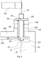
- the optical fiber 14 is shown in a position prior to its introduction and its fixing in the housing 16.
- the optical fiber 14 is a lenticular optical fiber and the laser diode 11 is a semiconductor diode electrically powered by electrodes 15.
- a ferrule 110 is hermetically welded around the optical fiber 14 by a glass-metal type weld, at a distance of a few hundred micrometers from the tip of the optical fiber 14.
- the optical fiber 14 has at its end a lens tip 27 in the form of a double bevel so as to reduce power losses in the coupling. It will be noted that on the figure 2 the tip of the optical fiber has been magnified so that it can be distinguished from the ferrule.
- the steel case 16 containing the laser diode 11 is open on top and can be sealed with a cover (not shown in this figure).
- This housing 16 has a light-forming fiber passage 113 formed in the wall 114 of the housing 16 and which extends into a tubular portion 115 which projects out of the housing 16 from the wall 114.
- the base 17 of the housing is screwed onto the base 15.
- the base 15 is fixed on an anti-vibratile table 12 and is temperature regulated to work at a given operating point temperature.
- a three-axis micro-positioning assembly 13 for moving the optical fiber 14 is placed on the table 12 near the base 15.
- the assembly 13 is equipped with translation plates controlled by actuators (not shown in this figure) and is extended by an optical fiber gripper 111 which encloses the optical fiber 14 using jaws 112 closed by compressed air.
- the base 15 is placed beneath a mobile laser welding head 18 connected to a pulsed Nd: YAG laser 19 by two optical fibers protected by thick sheaths.
- the YAG 19 laser has a peak power of 6kW and is configured to emit at 1064 nm.
- two laser welding heads that can be moved independently can be placed above the housing 16.
- a first magnetized washer 116 of ferromagnetic alloy, is pressed at the end of the tubular portion 115 and a second washer 117 is pressed against the inner face of the wall 114 vis-à-vis the light 113.
- the optical fiber 14 is successively inserted in the first washer 116, in the light 113 and then in the second washer until the ferrule 110 protrudes slightly from the washer 117 inside the housing 16 so that the tip of the optical fiber is spaced less than 2 millimeters from the washer 117.
- the washers 116 and 117 substantially identical, have a thickness of 0.3 millimeters.
- the diameter of the lumen 113 is greater than that of the ferrule 110 in order to facilitate the passage of the ferrule through the lumen 110 and the gap between the washers 116 and 117 is of a suitable value to protect the fiber laser diode leverage of the ferrule.
- the central orifice of the washer 117 is adjusted to the diameter of the ferrule 110. This orifice is also beveled relative to the axis of the washer so as to facilitate insertion of the ferrule in the washer 117.
- the washers 116 and 117 may be placed around the ferrule 110 as the optical fiber advances in the direction of the inside of the housing.
- the laser diode 11 is powered at nominal operating power, for example at 10W in the near infrared, and the micro-positioning assembly 13 progressively displaces the optical fiber 14 until it reaches an alignment position with the laser diode 11 in which the signal at the output of the optical fiber is of maximum amplitude.
- prior alignment of the optical fiber 14 with the laser diode can be carried out by feeding the laser diode 11 at 1 Ampere, close to the threshold of the laser emission.
- the YAG laser 19 emits a pulse in a direction 119 substantially tangent to the plane of the wall 114 in order to achieve a first weld point 22 between the second washer 117 and the ferrule 110.
- a direction substantially tangent to the plane of the wall is understood to mean a direction inclined at most 20 ° with respect to the surface of the wall 114.
- a second welding point 32 is made simultaneously between the ferrule 110 and the washer 117 by the YAG laser 19 in a direction of normal incidence relative to the direction of the first impulse.
- Two normal-action weld points 23 are then made by the YAG laser 19 between the first washer 116 and the ferrule 110, which sets the spacing between the tip of the optical fiber 14 and the laser diode 11.
- the optical fiber 14 is aligned again with the laser diode 11 using the micro-positioning assembly 13 in a position where the signal emitted at the output of the fiber is maximum.
- the YAG laser 19 then proceeds to two sets of two simultaneous laser shots in order to make two additional soldering points 24 and 34 in substantially perpendicular directions 35a and 35b (see FIG. figure 3a ) between each of the washers 116 and 117 and the portion tubular 115 and the wall 114, which freezes the alignment of the optical fiber in directions perpendicular to its axis.
- a solder alloy is deposited around the ferrule 110 through the radial bores 26 provided in the tubular portion 115 and the tubular portion 115 is heated until the solder alloy melts and is distributed all around the ferrule.
- the weld thus obtained makes it possible to ensure the tightness and the hermeticity of the wall 115 at the level of the light 113.
- the lid equipped with a seal of the housing 16 can then be screwed onto the body of the housing 16, which seals the housing 16 hermetically.
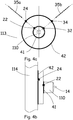
- two soldering points 22, 32 are made between the ferrule 110 and the washer 117 and two solder points 24, 34 between the washer 117 and the wall 114.
- a first circular weld bead 41 is formed between the ferrule 110 and the washer 117 and a second weld bead 42 is formed between the washer 117 and the wall 114, so as to ensure a hermetic closure of the wall 114 at the level of the light 113.
- the outer face of the wall 114 is flat and has no projection.
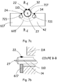
- the figure 6 is a sectional detail view of another embodiment of the fixation of an optical fiber 14 with a housing 610 for containing a laser diode 11.
- the housing 610 has a tubular portion 615 protruding from both sides of the wall 114, in which is inserted a ferrule 110 brewed on the optical fiber 14.
- the tubular portion 615 has been milled at its end facing the laser diode 11, in order to remove the upper portion thereof,
- the washer 617 has a rectangular base substantially conforming to the internal shape of the casing 610. It allows pre-positioning of the washer 617 in the casing 610, between the tubular portion 615 and the casing 610.
- This base plate 617 also comprises two oblong slots 721 intended to evacuate the heat from the welds and to ensure a substantially homogeneous temperature distribution in the washer 617.
- the washer 617 is fixed with the ferrule 110 by two points of welding 22 and 32 on the one hand. It is attached on the other hand to the tubular portion by two additional welding spots 24 and 34.
- the washer 617 comprises a thin portion forming a thinned arc 717, in the area of the welding points 22 and 32.
- the point of the arc 717 illuminated by the laser melts and spreads on the ferrule 110, filling the game present between the washer 617 and the ferrule 110, which increases the extent, and therefore the strength, of the weld point.
- the firing direction 119 of the YAG laser 19 to achieve the weld points 22 and 24, is substantially normal to the longitudinal axis of the optical fiber 14 and parallel to the wall 114.
- the YAG laser is oriented at 90 ° with respect to the firing direction corresponding to the weld points 22 and 24.
- the assembly thus obtained is very strong and withstands a pressure of 100 N / m 2 without the soldering points breaking.
- the Figures 8a and 8b illustrate the fixing, outside the housing 610, the washer 616, a thickness of 0.8mm, with, on the one hand, the ferrule 110 and the tubular portion 615 on the other.
- two weld points 23, 33 ensure the fixing of the ferrule 110 with the thin stud 816 of the washer 616.
- the washer 616 is fixed to the tubular portion 615 by two weld points 25 and 35 to approximately 140 °.
- the washer 616 is kept perfectly plated on the tubular portion 615, especially during the production of a sealing bead 42 sealing.
- the washer 616 has in its upper part a profile in the form of steps. This particular shape makes it possible to perform laser shots perpendicularly to the surface of the washer at the points of welding 25 and 35. It can thus bring more power at the points of welding 25, 35, which gives them a substantial strength.
- a second weld bead 41 hermetically seals the housing 610 at the passage of the optical fiber 14.
- the mounting station 510 of the optical fiber 14 will now be described in the optoelectronic package 610 illustrated with reference to FIG. figure 6 .
- the station 510 comprises a motorized table 581 intended to move the housing 610 in front of the fixed laser welding head 518, so as to align the zone to be welded with the lens 120 of the welding head 518.
- a motorized table 581 intended to move the housing 610 in front of the fixed laser welding head 518, so as to align the zone to be welded with the lens 120 of the welding head 518.
- On this table 581 are fixed the base 15 for holding the housing 610 and the micro-positioning assembly 13 of the optical fiber 14 relative to said laser diode 11.
- the base 15 is in the form of a parallelepiped block in invar, limiting the effects of expansion by heating.
- the base 15 is also equipped with heat sinks (not shown on the figure 5 ) for limiting the variations in height of the base 15 along the Y axis, in order to maintain precise positioning of the optical fiber 14 with respect to the laser diode 11, when the welding points are made.
- the assembly 13 six degrees of freedom, is equipped with translation plates, rotation and tilting. In particular, the assembly 13 is extended by a rotary head 520 whose axis of rotation coincides with the axis of revolution of the optical fiber.
- the rotary head 520 comprises a first optical fiber gripper 511, also called the first gripper, for holding the optical fiber, followed by a second gripper 512, or second gripper having a V-shaped groove pressing on the ferrule 110.
- gripper 512 is screwed to the rotary head 520 with a tightening torque greater than or equal to 15 centinewtons meter.
- the motorized table 581 When performing the welding points, the motorized table 581 under the effect of actuators (not shown on the figure 8 ), moves the housing 610 in a predetermined position facing the beam of the laser welding head 518.
- the laser welding head 518 is connected to the YAG 19 laser emitting at 1064 nm for a peak power maximum of 6kW, with a beam spot with a minimum diameter of 0.1mm.
Landscapes
- Physics & Mathematics (AREA)
- General Physics & Mathematics (AREA)
- Optics & Photonics (AREA)
- Optical Couplings Of Light Guides (AREA)
Claims (15)
- Verfahren zum Befestigen einer optischen Faser an einem Laserdiodenträger in einer Position, in der die optische Faser in optischer Kopplungsbeziehung mit der Laserdiode ist, wobei der Träger eine Öffnung aufweist, die in einer Wand des Trägers gebildet ist, die für den Durchgang der Faser bestimmt ist, dadurch gekennzeichnet, dass es die folgenden Schritte aufweist:- hermetisches Befestigen einer Ferrule auf der optischen Faser im Wesentlichen an einem Ende der Faser, wobei die Ferrule eine Länge aufweist, die größer als die Dicke der Öffnung ist;- Anbringen einer ersten und einer zweiten Unterlegscheibe gegenüber der Öffnung an beiden Seiten der Wand, wobei die Unterlegscheibe in Kontakt mit der Wand angebracht wird;- Anordnen der Ferrule derart, dass die Ferrule auf jeder Seite der Wand aus den Unterlegscheiben herausragt, umfassend einen Schritt des Einfügens der optischen Faser in die erste Unterlegscheibe und in die Öffnung;- Ausrichten der optischen Faser mit der Laserdiode in einer Position, die die optische Kopplung zwischen der Faser und der Diode optimiert, und Laserschweißen der Unterlegscheiben mit der Ferrule, umfassend einen Schritt des Emittierens eines Laserstrahls, der im Wesentlichen tangential zu der Wand und im Wesentlichen senkrecht zu der Achse der Faser ist;- Ausrichten der optischen Faser mit der Laserdiode in einer Position, die die optische Kopplung zwischen der Faser und der Diode optimiert, und Laserschweißen der Unterlegscheiben mit der Wand, umfassend einen Schritt des Emittierens eines Laserstrahls, der im Wesentlichen tangential zu der Wand und im Wesentlichen senkrecht zu der Achse der Faser ist.
- Verfahren nach Anspruch 1, dadurch gekennzeichnet, dass während des Schrittes des Anbringens die zweite Unterlegscheibe in Kontakt mit der Wand angebracht wird, und dass während des Schrittes des Einfügens die optische Faser in die erste und zweite Unterlegscheibe und in die Öffnung eingefügt wird.
- Verfahren nach einem der Ansprüche 1 und 2, dadurch gekennzeichnet, dass während des Schrittes des Einfügens der optischen Faser weniger als 1,5 mm des Endes der optischen Faser, die der Laserdiode zugewandt ist, aus der Unterlegscheibe herausragt, die gegen die Wand gedrückt wird, die der Laserdiode zugewandt ist.
- Verfahren nach einem der Ansprüche 1 bis 3, dadurch gekennzeichnet, dass die Schritte des Laserschweißens einen Schritt des Erstellens von mindestens einem Schweißpunkt zwischen der Ferrule und einer der Unterlegscheiben und von mindestens einem Schweißpunkt zwischen der Unterlegscheibe, die an die Ferrule angeschweißt wird, und der Wand aufweisen.
- Verfahren nach Anspruch 4, dadurch gekennzeichnet, dass zwei Schweißpunkte zwischen der Ferrule und mindestens einer der Unterlegscheiben und/oder zwischen mindestens einer der Unterlegscheiben und der Wand im Wesentlichen im rechten Winkel zueinander gegenüber der zentralen Achse der Faser erstellt werden.
- Verfahren nach einem der Ansprüche 1 bis 5, dadurch gekennzeichnet, dass die optische Faser eine mit Linse versehene optische Faser ist, deren Ende eine Spitze in Form einer Doppelabschrägung aufweist, deren Spitze eine Kante bildet.
- Verfahren nach Anspruch 6, dadurch gekennzeichnet, dass das die Kante gekrümmt ist.
- Verfahren nach Anspruch 6, dadurch gekennzeichnet, dass zwei Schweißpunkte zwischen der Ferrule und mindestens einer der Unterlegscheiben oder zwischen mindestens einer der Unterlegscheiben und der Wand in einer Richtung, die im Wesentlichen parallel zu der Kante ist, erstellt werden.
- Verfahren nach einem der Ansprüche 1 bis 8, dadurch gekennzeichnet, dass die Öffnung mindestens teilweise in einem hervorstehenden Teil der Wand, die zur Außenseite des Trägers gewandt ist, gebildet wird.
- Verfahren nach einem der Ansprüche 1 bis 9, dadurch gekennzeichnet, dass das zentrale Loch der Unterlegscheiben gegenüber der Achse der Unterlegscheibe abgeschrägt ist.
- Verfahren nach einem der Ansprüche 1 bis 10, dadurch gekennzeichnet, dass die Öffnung einen Durchmesser aufweist, der größer als jener der Ferrule ist.
- Verfahren nach einem der Ansprüche 1 bis 11, dadurch gekennzeichnet, dass der Träger ein Gehäuse ist, das geeignet ist, hermetisch abgedichtet zu werden.
- Verfahren nach einem der Ansprüche 1 bis 12, dadurch gekennzeichnet, dass es einen Schritt des Aufbringens durch mindestens ein Loch, das in der Wand gebildet wird, einer Lötlegierung um die Ferrule, die dazu bestimmt ist, die Dichtheit der Wand an der Öffnung zu garantieren.
- Verfahren nach einem der Ansprüche 1 bis 13, dadurch gekennzeichnet, dass mindestens einer der Schweißpunkte auf dem Rand von einer der Unterlegscheiben erstellt wird.
- Verfahren nach einem der Ansprüche 1 bis 14, dadurch gekennzeichnet, dass die erste Unterlegscheibe und/oder die zweite Unterlegscheibe einen dünneren Abschnitt aufweist, der dazu bestimmt ist, einen der Schweißpunkte aufzunehmen.
Applications Claiming Priority (1)
| Application Number | Priority Date | Filing Date | Title |
|---|---|---|---|
| FR1453623A FR3020144B1 (fr) | 2014-04-22 | 2014-04-22 | Procede de fixation d'une fibre optique avec un support d'une diode laser |
Publications (2)
| Publication Number | Publication Date |
|---|---|
| EP2937723A1 EP2937723A1 (de) | 2015-10-28 |
| EP2937723B1 true EP2937723B1 (de) | 2017-04-05 |
Family
ID=51417390
Family Applications (1)
| Application Number | Title | Priority Date | Filing Date |
|---|---|---|---|
| EP15164747.6A Active EP2937723B1 (de) | 2014-04-22 | 2015-04-22 | Verfahren zur befestigung einer optischen faser mit einer halterung einer laserdiode |
Country Status (2)
| Country | Link |
|---|---|
| EP (1) | EP2937723B1 (de) |
| FR (2) | FR3020144B1 (de) |
Families Citing this family (1)
| Publication number | Priority date | Publication date | Assignee | Title |
|---|---|---|---|---|
| CN106371177B (zh) * | 2016-10-17 | 2018-04-03 | 青岛海信宽带多媒体技术有限公司 | 一种光收发组件的组装方法 |
Family Cites Families (2)
| Publication number | Priority date | Publication date | Assignee | Title |
|---|---|---|---|---|
| US5793915A (en) * | 1997-07-03 | 1998-08-11 | Lucent Technologies Inc. | Thermal stress reduction in a laser module |
| US6659659B1 (en) * | 2001-04-11 | 2003-12-09 | Optical Communication Products, Inc. | High-speed optical sub-assembly utilizing ceramic substrate, direct coupling and laser welding |
-
2014
- 2014-04-22 FR FR1453623A patent/FR3020144B1/fr not_active Expired - Fee Related
-
2015
- 2015-04-22 EP EP15164747.6A patent/EP2937723B1/de active Active
- 2015-04-22 FR FR1553616A patent/FR3020145B1/fr not_active Expired - Fee Related
Non-Patent Citations (1)
| Title |
|---|
| None * |
Also Published As
| Publication number | Publication date |
|---|---|
| FR3020144B1 (fr) | 2017-11-03 |
| EP2937723A1 (de) | 2015-10-28 |
| FR3020145A1 (fr) | 2015-10-23 |
| FR3020145B1 (fr) | 2016-08-19 |
| FR3020144A1 (fr) | 2015-10-23 |
Similar Documents
| Publication | Publication Date | Title |
|---|---|---|
| EP0481876B1 (de) | Justierverfahren der optischen Achsen von einer Faser und von einem optoelektronischen Bauelement und die mit diesem Verfahren hergestellte Vorrichtung | |
| EP0017701A1 (de) | Auf einem Substrat angeordnete Kupplungsvorrichtung für optischen Übertrager | |
| EP0183124A1 (de) | Optische Lichtquelle | |
| EP0112211B1 (de) | Verfahren zum Ausrichten eines optoelektronischen Gerätes | |
| FR2466784A1 (fr) | Tete de couplage opto-electronique, et procede de montage d'une telle tete | |
| EP3157050A1 (de) | Herstellungsverfahren einer mikroelektronischen vorrichtung | |
| FR3079765A1 (fr) | Procede et dispositif de soudage laser d'une premiere piece sur une seconde piece | |
| EP2937723B1 (de) | Verfahren zur befestigung einer optischen faser mit einer halterung einer laserdiode | |
| EP0176154B1 (de) | Verfahren zur Herstellung von einem Endbestandteil für eine optische Faser und Bestandteil so erhältlich | |
| FR2690996A1 (fr) | Dispositif d'alignement optique entre un composant optoélectronique et un composant optique, et procédé d'alignement. | |
| EP1451624A2 (de) | Modul für optische verbindungen | |
| EP0779525A1 (de) | Vorrichtung für die Einkopplung eines Leistungslaserstrahls in eine optische Faser | |
| FR2820790A1 (fr) | Procede et dispositif de fixation mecanique d'un composant optique | |
| WO2010010241A1 (fr) | D'un element pour former une lentille; dispositif, element de ce dispositif et raccord pour la mise en oeuvre de ce procede | |
| FR2661005A1 (fr) | Dispositif d'alignement et de fixation d'une fibre optique devant un laser semiconducteur. | |
| WO2006051225A1 (fr) | Procede de soudure laser sans apport de matiere et dispositif electrique susceptible d'etre realise par ce procede | |
| EP1824779A1 (de) | Vorrichtung und verfahren zur hermetischen abdichtung eines hohlraums in einem elektronischen bauteil | |
| FR3030785A1 (fr) | Systeme de transmission d'une lumiere laser a travers une paroi comprenant un cordon pour evacuer des modes de gaine et procede de fabrication correspondant | |
| FR2864699A1 (fr) | Assemblage d'un composant monte sur une surface de report | |
| FR2919757A1 (fr) | Technique d'assemblage de sous-ensemble optoelectronique | |
| FR2737310A1 (fr) | Procede et dispositif de couplage entre une fibre optique et un laser ou un photodetecteur | |
| WO2009118484A2 (fr) | Sous-ensemble optoelectronique | |
| EP0593335B1 (de) | Bauteil zur optischen Kopplung | |
| BE1000067A7 (fr) | Appareil et procede en vue de coupler une fibre optique monomode en queue de cochon a une photodiode. | |
| FR2921753A1 (fr) | Sous-ensemble optoelectronique et procede d'assemblage de ce sous-ensemble |
Legal Events
| Date | Code | Title | Description |
|---|---|---|---|
| PUAI | Public reference made under article 153(3) epc to a published international application that has entered the european phase |
Free format text: ORIGINAL CODE: 0009012 |
|
| AK | Designated contracting states |
Kind code of ref document: A1 Designated state(s): AL AT BE BG CH CY CZ DE DK EE ES FI FR GB GR HR HU IE IS IT LI LT LU LV MC MK MT NL NO PL PT RO RS SE SI SK SM TR |
|
| AX | Request for extension of the european patent |
Extension state: BA ME |
|
| 17P | Request for examination filed |
Effective date: 20160419 |
|
| RBV | Designated contracting states (corrected) |
Designated state(s): AL AT BE BG CH CY CZ DE DK EE ES FI FR GB GR HR HU IE IS IT LI LT LU LV MC MK MT NL NO PL PT RO RS SE SI SK SM TR |
|
| GRAP | Despatch of communication of intention to grant a patent |
Free format text: ORIGINAL CODE: EPIDOSNIGR1 |
|
| INTG | Intention to grant announced |
Effective date: 20161208 |
|
| GRAS | Grant fee paid |
Free format text: ORIGINAL CODE: EPIDOSNIGR3 |
|
| GRAA | (expected) grant |
Free format text: ORIGINAL CODE: 0009210 |
|
| AK | Designated contracting states |
Kind code of ref document: B1 Designated state(s): AL AT BE BG CH CY CZ DE DK EE ES FI FR GB GR HR HU IE IS IT LI LT LU LV MC MK MT NL NO PL PT RO RS SE SI SK SM TR |
|
| REG | Reference to a national code |
Ref country code: GB Ref legal event code: FG4D Free format text: NOT ENGLISH |
|
| REG | Reference to a national code |
Ref country code: CH Ref legal event code: EP |
|
| REG | Reference to a national code |
Ref country code: AT Ref legal event code: REF Ref document number: 882328 Country of ref document: AT Kind code of ref document: T Effective date: 20170415 |
|
| REG | Reference to a national code |
Ref country code: FR Ref legal event code: PLFP Year of fee payment: 3 |
|
| REG | Reference to a national code |
Ref country code: IE Ref legal event code: FG4D Free format text: LANGUAGE OF EP DOCUMENT: FRENCH |
|
| REG | Reference to a national code |
Ref country code: DE Ref legal event code: R096 Ref document number: 602015002090 Country of ref document: DE |
|
| REG | Reference to a national code |
Ref country code: NL Ref legal event code: MP Effective date: 20170405 |
|
| REG | Reference to a national code |
Ref country code: LT Ref legal event code: MG4D |
|
| REG | Reference to a national code |
Ref country code: AT Ref legal event code: MK05 Ref document number: 882328 Country of ref document: AT Kind code of ref document: T Effective date: 20170405 |
|
| PG25 | Lapsed in a contracting state [announced via postgrant information from national office to epo] |
Ref country code: NL Free format text: LAPSE BECAUSE OF FAILURE TO SUBMIT A TRANSLATION OF THE DESCRIPTION OR TO PAY THE FEE WITHIN THE PRESCRIBED TIME-LIMIT Effective date: 20170405 |
|
| PG25 | Lapsed in a contracting state [announced via postgrant information from national office to epo] |
Ref country code: HR Free format text: LAPSE BECAUSE OF FAILURE TO SUBMIT A TRANSLATION OF THE DESCRIPTION OR TO PAY THE FEE WITHIN THE PRESCRIBED TIME-LIMIT Effective date: 20170405 Ref country code: NO Free format text: LAPSE BECAUSE OF FAILURE TO SUBMIT A TRANSLATION OF THE DESCRIPTION OR TO PAY THE FEE WITHIN THE PRESCRIBED TIME-LIMIT Effective date: 20170705 Ref country code: LT Free format text: LAPSE BECAUSE OF FAILURE TO SUBMIT A TRANSLATION OF THE DESCRIPTION OR TO PAY THE FEE WITHIN THE PRESCRIBED TIME-LIMIT Effective date: 20170405 Ref country code: AT Free format text: LAPSE BECAUSE OF FAILURE TO SUBMIT A TRANSLATION OF THE DESCRIPTION OR TO PAY THE FEE WITHIN THE PRESCRIBED TIME-LIMIT Effective date: 20170405 Ref country code: FI Free format text: LAPSE BECAUSE OF FAILURE TO SUBMIT A TRANSLATION OF THE DESCRIPTION OR TO PAY THE FEE WITHIN THE PRESCRIBED TIME-LIMIT Effective date: 20170405 Ref country code: GR Free format text: LAPSE BECAUSE OF FAILURE TO SUBMIT A TRANSLATION OF THE DESCRIPTION OR TO PAY THE FEE WITHIN THE PRESCRIBED TIME-LIMIT Effective date: 20170706 Ref country code: ES Free format text: LAPSE BECAUSE OF FAILURE TO SUBMIT A TRANSLATION OF THE DESCRIPTION OR TO PAY THE FEE WITHIN THE PRESCRIBED TIME-LIMIT Effective date: 20170405 |
|
| PG25 | Lapsed in a contracting state [announced via postgrant information from national office to epo] |
Ref country code: BG Free format text: LAPSE BECAUSE OF FAILURE TO SUBMIT A TRANSLATION OF THE DESCRIPTION OR TO PAY THE FEE WITHIN THE PRESCRIBED TIME-LIMIT Effective date: 20170705 Ref country code: LV Free format text: LAPSE BECAUSE OF FAILURE TO SUBMIT A TRANSLATION OF THE DESCRIPTION OR TO PAY THE FEE WITHIN THE PRESCRIBED TIME-LIMIT Effective date: 20170405 Ref country code: IS Free format text: LAPSE BECAUSE OF FAILURE TO SUBMIT A TRANSLATION OF THE DESCRIPTION OR TO PAY THE FEE WITHIN THE PRESCRIBED TIME-LIMIT Effective date: 20170805 Ref country code: SE Free format text: LAPSE BECAUSE OF FAILURE TO SUBMIT A TRANSLATION OF THE DESCRIPTION OR TO PAY THE FEE WITHIN THE PRESCRIBED TIME-LIMIT Effective date: 20170405 Ref country code: RS Free format text: LAPSE BECAUSE OF FAILURE TO SUBMIT A TRANSLATION OF THE DESCRIPTION OR TO PAY THE FEE WITHIN THE PRESCRIBED TIME-LIMIT Effective date: 20170405 Ref country code: PL Free format text: LAPSE BECAUSE OF FAILURE TO SUBMIT A TRANSLATION OF THE DESCRIPTION OR TO PAY THE FEE WITHIN THE PRESCRIBED TIME-LIMIT Effective date: 20170405 |
|
| REG | Reference to a national code |
Ref country code: DE Ref legal event code: R097 Ref document number: 602015002090 Country of ref document: DE |
|
| REG | Reference to a national code |
Ref country code: IE Ref legal event code: MM4A |
|
| PG25 | Lapsed in a contracting state [announced via postgrant information from national office to epo] |
Ref country code: EE Free format text: LAPSE BECAUSE OF FAILURE TO SUBMIT A TRANSLATION OF THE DESCRIPTION OR TO PAY THE FEE WITHIN THE PRESCRIBED TIME-LIMIT Effective date: 20170405 Ref country code: CZ Free format text: LAPSE BECAUSE OF FAILURE TO SUBMIT A TRANSLATION OF THE DESCRIPTION OR TO PAY THE FEE WITHIN THE PRESCRIBED TIME-LIMIT Effective date: 20170405 Ref country code: RO Free format text: LAPSE BECAUSE OF FAILURE TO SUBMIT A TRANSLATION OF THE DESCRIPTION OR TO PAY THE FEE WITHIN THE PRESCRIBED TIME-LIMIT Effective date: 20170405 Ref country code: SK Free format text: LAPSE BECAUSE OF FAILURE TO SUBMIT A TRANSLATION OF THE DESCRIPTION OR TO PAY THE FEE WITHIN THE PRESCRIBED TIME-LIMIT Effective date: 20170405 Ref country code: MC Free format text: LAPSE BECAUSE OF FAILURE TO SUBMIT A TRANSLATION OF THE DESCRIPTION OR TO PAY THE FEE WITHIN THE PRESCRIBED TIME-LIMIT Effective date: 20170405 Ref country code: DK Free format text: LAPSE BECAUSE OF FAILURE TO SUBMIT A TRANSLATION OF THE DESCRIPTION OR TO PAY THE FEE WITHIN THE PRESCRIBED TIME-LIMIT Effective date: 20170405 |
|
| PLBE | No opposition filed within time limit |
Free format text: ORIGINAL CODE: 0009261 |
|
| STAA | Information on the status of an ep patent application or granted ep patent |
Free format text: STATUS: NO OPPOSITION FILED WITHIN TIME LIMIT |
|
| PG25 | Lapsed in a contracting state [announced via postgrant information from national office to epo] |
Ref country code: LU Free format text: LAPSE BECAUSE OF NON-PAYMENT OF DUE FEES Effective date: 20170422 Ref country code: SM Free format text: LAPSE BECAUSE OF FAILURE TO SUBMIT A TRANSLATION OF THE DESCRIPTION OR TO PAY THE FEE WITHIN THE PRESCRIBED TIME-LIMIT Effective date: 20170405 Ref country code: IT Free format text: LAPSE BECAUSE OF FAILURE TO SUBMIT A TRANSLATION OF THE DESCRIPTION OR TO PAY THE FEE WITHIN THE PRESCRIBED TIME-LIMIT Effective date: 20170405 |
|
| 26N | No opposition filed |
Effective date: 20180108 |
|
| REG | Reference to a national code |
Ref country code: BE Ref legal event code: MM Effective date: 20170430 |
|
| REG | Reference to a national code |
Ref country code: FR Ref legal event code: PLFP Year of fee payment: 4 |
|
| PG25 | Lapsed in a contracting state [announced via postgrant information from national office to epo] |
Ref country code: IE Free format text: LAPSE BECAUSE OF NON-PAYMENT OF DUE FEES Effective date: 20170422 |
|
| PG25 | Lapsed in a contracting state [announced via postgrant information from national office to epo] |
Ref country code: SI Free format text: LAPSE BECAUSE OF FAILURE TO SUBMIT A TRANSLATION OF THE DESCRIPTION OR TO PAY THE FEE WITHIN THE PRESCRIBED TIME-LIMIT Effective date: 20170405 Ref country code: BE Free format text: LAPSE BECAUSE OF NON-PAYMENT OF DUE FEES Effective date: 20170430 |
|
| PG25 | Lapsed in a contracting state [announced via postgrant information from national office to epo] |
Ref country code: MT Free format text: LAPSE BECAUSE OF FAILURE TO SUBMIT A TRANSLATION OF THE DESCRIPTION OR TO PAY THE FEE WITHIN THE PRESCRIBED TIME-LIMIT Effective date: 20170405 |
|
| REG | Reference to a national code |
Ref country code: CH Ref legal event code: PL |
|
| PG25 | Lapsed in a contracting state [announced via postgrant information from national office to epo] |
Ref country code: LI Free format text: LAPSE BECAUSE OF NON-PAYMENT OF DUE FEES Effective date: 20180430 Ref country code: CH Free format text: LAPSE BECAUSE OF NON-PAYMENT OF DUE FEES Effective date: 20180430 |
|
| PG25 | Lapsed in a contracting state [announced via postgrant information from national office to epo] |
Ref country code: HU Free format text: LAPSE BECAUSE OF FAILURE TO SUBMIT A TRANSLATION OF THE DESCRIPTION OR TO PAY THE FEE WITHIN THE PRESCRIBED TIME-LIMIT; INVALID AB INITIO Effective date: 20150422 |
|
| PG25 | Lapsed in a contracting state [announced via postgrant information from national office to epo] |
Ref country code: CY Free format text: LAPSE BECAUSE OF FAILURE TO SUBMIT A TRANSLATION OF THE DESCRIPTION OR TO PAY THE FEE WITHIN THE PRESCRIBED TIME-LIMIT Effective date: 20170405 |
|
| PG25 | Lapsed in a contracting state [announced via postgrant information from national office to epo] |
Ref country code: MK Free format text: LAPSE BECAUSE OF FAILURE TO SUBMIT A TRANSLATION OF THE DESCRIPTION OR TO PAY THE FEE WITHIN THE PRESCRIBED TIME-LIMIT Effective date: 20170405 |
|
| GBPC | Gb: european patent ceased through non-payment of renewal fee |
Effective date: 20190422 |
|
| PG25 | Lapsed in a contracting state [announced via postgrant information from national office to epo] |
Ref country code: GB Free format text: LAPSE BECAUSE OF NON-PAYMENT OF DUE FEES Effective date: 20190422 |
|
| PG25 | Lapsed in a contracting state [announced via postgrant information from national office to epo] |
Ref country code: TR Free format text: LAPSE BECAUSE OF FAILURE TO SUBMIT A TRANSLATION OF THE DESCRIPTION OR TO PAY THE FEE WITHIN THE PRESCRIBED TIME-LIMIT Effective date: 20170405 |
|
| PG25 | Lapsed in a contracting state [announced via postgrant information from national office to epo] |
Ref country code: PT Free format text: LAPSE BECAUSE OF FAILURE TO SUBMIT A TRANSLATION OF THE DESCRIPTION OR TO PAY THE FEE WITHIN THE PRESCRIBED TIME-LIMIT Effective date: 20170405 |
|
| PG25 | Lapsed in a contracting state [announced via postgrant information from national office to epo] |
Ref country code: AL Free format text: LAPSE BECAUSE OF FAILURE TO SUBMIT A TRANSLATION OF THE DESCRIPTION OR TO PAY THE FEE WITHIN THE PRESCRIBED TIME-LIMIT Effective date: 20170405 |
|
| PGFP | Annual fee paid to national office [announced via postgrant information from national office to epo] |
Ref country code: FR Payment date: 20230403 Year of fee payment: 9 Ref country code: DE Payment date: 20230406 Year of fee payment: 9 |
|
| REG | Reference to a national code |
Ref country code: DE Ref legal event code: R081 Ref document number: 602015002090 Country of ref document: DE Owner name: KEOPSYS INDUSTRIES, FR Free format text: FORMER OWNER: KEOPSYS, LANNION, FR |