EP2175506A2 - Batterie secondaire - Google Patents
Batterie secondaire Download PDFInfo
- Publication number
- EP2175506A2 EP2175506A2 EP09172464A EP09172464A EP2175506A2 EP 2175506 A2 EP2175506 A2 EP 2175506A2 EP 09172464 A EP09172464 A EP 09172464A EP 09172464 A EP09172464 A EP 09172464A EP 2175506 A2 EP2175506 A2 EP 2175506A2
- Authority
- EP
- European Patent Office
- Prior art keywords
- side walls
- long side
- secondary battery
- insulating case
- outer surfaces
- Prior art date
- Legal status (The legal status is an assumption and is not a legal conclusion. Google has not performed a legal analysis and makes no representation as to the accuracy of the status listed.)
- Granted
Links
- 238000007789 sealing Methods 0.000 claims abstract description 3
- 239000003792 electrolyte Substances 0.000 description 9
- 238000002347 injection Methods 0.000 description 6
- 239000007924 injection Substances 0.000 description 6
- WHXSMMKQMYFTQS-UHFFFAOYSA-N Lithium Chemical compound [Li] WHXSMMKQMYFTQS-UHFFFAOYSA-N 0.000 description 4
- 238000010276 construction Methods 0.000 description 4
- 239000011810 insulating material Substances 0.000 description 4
- 229910052744 lithium Inorganic materials 0.000 description 4
- 230000015572 biosynthetic process Effects 0.000 description 3
- PXHVJJICTQNCMI-UHFFFAOYSA-N Nickel Chemical compound [Ni] PXHVJJICTQNCMI-UHFFFAOYSA-N 0.000 description 2
- 239000000758 substrate Substances 0.000 description 2
- 229910000838 Al alloy Inorganic materials 0.000 description 1
- HBBGRARXTFLTSG-UHFFFAOYSA-N Lithium ion Chemical compound [Li+] HBBGRARXTFLTSG-UHFFFAOYSA-N 0.000 description 1
- 229910000990 Ni alloy Inorganic materials 0.000 description 1
- 229910052782 aluminium Inorganic materials 0.000 description 1
- XAGFODPZIPBFFR-UHFFFAOYSA-N aluminium Chemical compound [Al] XAGFODPZIPBFFR-UHFFFAOYSA-N 0.000 description 1
- 230000001413 cellular effect Effects 0.000 description 1
- 230000007547 defect Effects 0.000 description 1
- 229910052739 hydrogen Inorganic materials 0.000 description 1
- 239000001257 hydrogen Substances 0.000 description 1
- 239000012535 impurity Substances 0.000 description 1
- 238000003780 insertion Methods 0.000 description 1
- 230000037431 insertion Effects 0.000 description 1
- 230000002452 interceptive effect Effects 0.000 description 1
- 229910001416 lithium ion Inorganic materials 0.000 description 1
- 239000000463 material Substances 0.000 description 1
- 229910052751 metal Inorganic materials 0.000 description 1
- 239000002184 metal Substances 0.000 description 1
- 229910052759 nickel Inorganic materials 0.000 description 1
- QELJHCBNGDEXLD-UHFFFAOYSA-N nickel zinc Chemical compound [Ni].[Zn] QELJHCBNGDEXLD-UHFFFAOYSA-N 0.000 description 1
- 239000013585 weight reducing agent Substances 0.000 description 1
- 238000003466 welding Methods 0.000 description 1
Images


Classifications
-
- H—ELECTRICITY
- H01—ELECTRIC ELEMENTS
- H01M—PROCESSES OR MEANS, e.g. BATTERIES, FOR THE DIRECT CONVERSION OF CHEMICAL ENERGY INTO ELECTRICAL ENERGY
- H01M10/00—Secondary cells; Manufacture thereof
- H01M10/04—Construction or manufacture in general
- H01M10/0431—Cells with wound or folded electrodes
-
- H—ELECTRICITY
- H01—ELECTRIC ELEMENTS
- H01M—PROCESSES OR MEANS, e.g. BATTERIES, FOR THE DIRECT CONVERSION OF CHEMICAL ENERGY INTO ELECTRICAL ENERGY
- H01M10/00—Secondary cells; Manufacture thereof
- H01M10/05—Accumulators with non-aqueous electrolyte
- H01M10/058—Construction or manufacture
- H01M10/0587—Construction or manufacture of accumulators having only wound construction elements, i.e. wound positive electrodes, wound negative electrodes and wound separators
-
- H—ELECTRICITY
- H01—ELECTRIC ELEMENTS
- H01M—PROCESSES OR MEANS, e.g. BATTERIES, FOR THE DIRECT CONVERSION OF CHEMICAL ENERGY INTO ELECTRICAL ENERGY
- H01M50/00—Constructional details or processes of manufacture of the non-active parts of electrochemical cells other than fuel cells, e.g. hybrid cells
- H01M50/10—Primary casings; Jackets or wrappings
- H01M50/116—Primary casings; Jackets or wrappings characterised by the material
- H01M50/117—Inorganic material
- H01M50/119—Metals
-
- H—ELECTRICITY
- H01—ELECTRIC ELEMENTS
- H01M—PROCESSES OR MEANS, e.g. BATTERIES, FOR THE DIRECT CONVERSION OF CHEMICAL ENERGY INTO ELECTRICAL ENERGY
- H01M10/00—Secondary cells; Manufacture thereof
- H01M10/05—Accumulators with non-aqueous electrolyte
- H01M10/052—Li-accumulators
- H01M10/0525—Rocking-chair batteries, i.e. batteries with lithium insertion or intercalation in both electrodes; Lithium-ion batteries
-
- H—ELECTRICITY
- H01—ELECTRIC ELEMENTS
- H01M—PROCESSES OR MEANS, e.g. BATTERIES, FOR THE DIRECT CONVERSION OF CHEMICAL ENERGY INTO ELECTRICAL ENERGY
- H01M50/00—Constructional details or processes of manufacture of the non-active parts of electrochemical cells other than fuel cells, e.g. hybrid cells
- H01M50/10—Primary casings; Jackets or wrappings
- H01M50/116—Primary casings; Jackets or wrappings characterised by the material
- H01M50/124—Primary casings; Jackets or wrappings characterised by the material having a layered structure
-
- H—ELECTRICITY
- H01—ELECTRIC ELEMENTS
- H01M—PROCESSES OR MEANS, e.g. BATTERIES, FOR THE DIRECT CONVERSION OF CHEMICAL ENERGY INTO ELECTRICAL ENERGY
- H01M50/00—Constructional details or processes of manufacture of the non-active parts of electrochemical cells other than fuel cells, e.g. hybrid cells
- H01M50/50—Current conducting connections for cells or batteries
- H01M50/543—Terminals
- H01M50/552—Terminals characterised by their shape
- H01M50/553—Terminals adapted for prismatic, pouch or rectangular cells
-
- Y—GENERAL TAGGING OF NEW TECHNOLOGICAL DEVELOPMENTS; GENERAL TAGGING OF CROSS-SECTIONAL TECHNOLOGIES SPANNING OVER SEVERAL SECTIONS OF THE IPC; TECHNICAL SUBJECTS COVERED BY FORMER USPC CROSS-REFERENCE ART COLLECTIONS [XRACs] AND DIGESTS
- Y02—TECHNOLOGIES OR APPLICATIONS FOR MITIGATION OR ADAPTATION AGAINST CLIMATE CHANGE
- Y02E—REDUCTION OF GREENHOUSE GAS [GHG] EMISSIONS, RELATED TO ENERGY GENERATION, TRANSMISSION OR DISTRIBUTION
- Y02E60/00—Enabling technologies; Technologies with a potential or indirect contribution to GHG emissions mitigation
- Y02E60/10—Energy storage using batteries
-
- Y—GENERAL TAGGING OF NEW TECHNOLOGICAL DEVELOPMENTS; GENERAL TAGGING OF CROSS-SECTIONAL TECHNOLOGIES SPANNING OVER SEVERAL SECTIONS OF THE IPC; TECHNICAL SUBJECTS COVERED BY FORMER USPC CROSS-REFERENCE ART COLLECTIONS [XRACs] AND DIGESTS
- Y02—TECHNOLOGIES OR APPLICATIONS FOR MITIGATION OR ADAPTATION AGAINST CLIMATE CHANGE
- Y02P—CLIMATE CHANGE MITIGATION TECHNOLOGIES IN THE PRODUCTION OR PROCESSING OF GOODS
- Y02P70/00—Climate change mitigation technologies in the production process for final industrial or consumer products
- Y02P70/50—Manufacturing or production processes characterised by the final manufactured product
Definitions
- the invention relates to a secondary battery.
- Secondary batteries may include, e.g., nickelcadmium batteries, nickel-hydrogen batteries, nickel-zinc batteries and lithium secondary batteries.
- Lithium batteries are widely used in state-of-the-art electronic devices due to their, e.g., rechargeability, smaller size, larger capacity, higher operating voltage and higher energy density per unit weight.
- a typical lithium battery is fabricated by accommodating an electrode assembly, including a positive electrode plate, a negative electrode plate and a separator, together with an electrolyte in a can. Then, the upper opening of the can is closed with a cap assembly to seal the can. An insulating case may be inserted into the can to prevent a short between the cap assembly and the electrode assembly.
- a typical insulating case may simply be placed on the upper end of the electrode assembly. This configuration, however, may cause the insulating case to spring out of the can. That is, the insulating case may not be stably seated inside the can. Typical lithium secondary batteries may have a problem associated with the insertion of the insulating case into the can.
- the typical lithium ion battery includes an insulating case that is wider than the upper opening of the can, the insulating case may interfere with the can and leave burrs.
- the burrs may be impurities during welding of the cap assembly to the upper opening of the can and may thereby cause defects during assembly.
- Embodiments are therefore directed to a secondary battery, which substantially overcome one or more of the problems due to the limitations and disadvantages of the related art.
- a secondary battery including an electrode assembly, a can accommodating the electrode assembly, a cap assembly sealing the can, and an insulating case interposed between the electrode assembly and the cap assembly and having two facing long side walls and two facing short side walls, wherein the two facing long side walls include opposing end portions and opposing central portions, the opposing end portions and the opposing central portions each include outer surfaces and a distance between the outer surfaces of the opposing end portions of the long side walls is greater than a distance between the outer surfaces of the opposing central portions of the long side walls.
- Each of the long side walls may have a linear shape in cross section and each of the short side walls may have a circular-arc shape in cross section.
- the short side walls may be thicker than the long side walls.
- the insulating case may have tapered portions at positions where the long side walls meet the short side walls.
- the tapered portions may be angled inwardly toward the long side walls from the short side walls.
- the tapered portions may be angled inwardly at an angle of about 1 ° to about 10°.
- the insulating case may have protrusions extending outwardly from the long side walls.
- the protrusions may include outer surfaces, the protrusions may be disposed in pairs on opposing outer surfaces of the long side walls and a distance between the outer surfaces of the pairs of protrusions may be greater than a distance between the outer surfaces of the opposing end portions of the long side walls.
- Each of the protrusions may extend outwardly from the long side wall at a distance of about 0.075 to about 0.095 mm.
- Each of the protrusions may extend outwardly from the long side wall at a distance of about 0.085 mm.
- FIG. 1 illustrates an exploded perspective view of a secondary battery according to an embodiment.
- FIG. 2 illustrates a plan view of an insulating case of the secondary battery of FIG. 1 .
- FIG. 3 illustrates a partial enlarged view of a side portion of the insulating case of FIG. 2 .
- FIG. 4 illustrates a plan view of a state in which the insulating case of FIG 2 is inserted into a can.
- the second battery 100 may include an electrode assembly 110, a can 120 accommodating the electrode assembly 110, a cap assembly 130 closing an opening of the can 120 to seal the can 120 and an insulating case 140 interposed between the electrode assembly 110 and the cap assembly 130.
- the electrode assembly 110 may be a laminate of a positive electrode plate 111, a negative electrode plate 112 and a separator 113 interposed between the two electrode plates.
- the laminate may be rolled in a jelly-roll configuration.
- a positive electrode tab 114 may be coupled to the positive electrode plate 111 and may protrude outwardly from the electrode assembly 110.
- a negative electrode tab 115 may be coupled to the negative electrode plate 112 and may protrude outwardly from the electrode assembly 110.
- the positive electrode tab 114 may be spaced apart from and electrically insulated from the negative electrode tab 115.
- the positive electrode tab 114 and the negative electrode tab 115 preferably include nickel, but there is no restriction on the material for the positive and negative electrode tabs.
- the can 120 may include, e.g., aluminum or aluminum alloys.
- the can 120 may be produced by, e.g., deep drawing.
- the can 120 may have an opening 120a at the upper end thereof, into which the electrode assembly 110 may be inserted.
- the can 120 may have two long side walls 121, two short side walls 122 and a bottom wall 123 connecting the long side walls and the short side walls.
- the cap assembly 130 may include a cap plate 131, a gasket 132, an electrode terminal 133, an insulating plate 134 and a terminal plate 135.
- the cap plate 131 may be made of, e.g., metal.
- the cap plate 131 may have a shape that corresponds to the shape of the upper opening 120a of the can 120.
- the cap plate 131 may have a terminal through-hole 131 a disposed at a center thereof.
- the cap plate 131 may have an electrolyte injection hole 131 b disposed at a side of the terminal through-hole 131 a.
- the electrolyte injection hole 131 b may be closed with a stopper 137.
- the positive electrode tab 114 coupled to the positive electrode plate 111 may be welded to the cap plate 131.
- the gasket 132 may be a tubular insulating material and may surround the periphery of the electrode terminal 133 when the electrode terminal 133 is inserted into the terminal through-hole 131 a.
- the electrode terminal 133 may be electrically connected to the electrode assembly 110 and may penetrate the cap plate 131, the insulating plate 134 and the terminal plate 135 during assembly of the secondary battery.
- the insulating plate 134 may be made of an insulating material, and may be coupled to the lower surface of the cap plate 131.
- the insulating plate 134 may have a terminal through-hole 134a into which the electrode terminal 133 may be inserted at a position corresponding to the terminal through-hole 131 a of the cap plate 131.
- the terminal plate 135 may include, e.g., a nickel alloy, and may be coupled to the lower surface of the insulating plate 134.
- the terminal plate 135 may have a terminal through-hole 135a into which the electrode terminal 133 may be inserted at a position corresponding to the terminal through-hole 131 a of the cap plate 131.
- the terminal plate 135 may be insulated from the cap plate 131 and may be electrically connected to the electrode terminal 133.
- the negative electrode tab 115 coupled to the negative electrode plate 112 may be welded to a side of the terminal plate 135.
- the insulating case 140 may have a rounded rectangular shape in cross section that corresponds to the size of the upper opening 120a.
- the insulating case 140 may be inserted into the can 120 and may be made of an insulating material.
- the insulating case 140 may have a bottom plate 141 and two long side walls 142 and two short side walls 143 surrounding the periphery of the bottom plate 141.
- the bottom plate 141 may have a substantially rectangular shape corresponding to the size of the upper opening 120a of the can 120.
- the insulating case 140 may have through-holes 140a and 140b through which the positive electrode tab 114 and the negative electrode tab 115 may penetrate, respectively.
- Each of the long side walls 142 may have a linear shape in cross section.
- Each of the short side walls 143 may have a circular-arc shape in cross section at both end portions of the long side wall 142.
- the short side walls 143 may be thicker than the long side walls 142. This structure of the side walls may be suitable for the formation of tapered portions 145 at positions where the long side walls 142 meet the short side walls 143.
- the tapered portions 145 may be disposed at the end portions of the long side walls 142.
- the tapered portions 145 may be angled inwardly from the short side walls 143 (starting points S) to the long side walls 142 (end points E).
- the distance (H2) between the outer surfaces of opposing end portions of the long side walls 142 may be greater than the distance (H1) between the outer surfaces of opposing central portions of the long side walls 142 (i.e. H1 ⁇ H2).
- the tapered portions 145 may be angled at an angle (a) of about 1 ° to about 10 °. Maintaining the angle (a) at about 1 ° or greater may help ensure that the end portions of the long side walls 142 contact the inner surfaces of the can 120. Maintaining the angle (a) at about 10 ° or less may help ensure that the end portions of the long side walls 142 do not interfere with the inner surfaces of the can 120 so that the insulating case 140 may be easily inserted into the can 120.
- This angular geometry may make the tapered portions 145 at end portions of the long side walls 142 very close to the four corners of the insulating case 140. Due to this construction, the insulating case 140 may be maintained in intimate contact with the four corners of the can 140.
- the electrode assembly 110 and the insulating case 140 may be sequentially inserted into the can 120. Then, the upper opening 120a of the can 120 may be closed with the cap assembly 130 to seal the can 120. After an electrolyte is injected into the can 120 through the electrolyte injection hole 131b of the cap plate 131, the electrolyte injection hole 131 b may be closed with the stopper 137.
- the insulating case 140 may be brought into intimate contact with the inner surfaces of the can 120 by the tapered portions 145 disposed at the four corners A, B, C and D thereof.
- the insulating case 140 may be fully inserted into the can 120 and be positioned on the upper surface of the electrode assembly 110. Further, the end portions of the long side walls 142, on which the tapered portions 145 may be formed, may be in contact with the four corners A, B, C and D of the inner surface of the can 120 so as not to leave gaps therebetween. As a result, the insulating case 140 may be stably maintained in a fixed state with the can 120 without being undesirably withdrawn from the can 120.
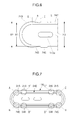
- FIG. 5 illustrates a plan view of an insulating case of a secondary battery according to another embodiment.
- FIG. 6 illustrates a partial enlarged view of a side portion of the insulating case of FIG. 5 .
- FIG. 7 illustrates a plan view of a state in which the insulating case of FIG 5 is inserted into a can.
- the secondary battery includes an electrode assembly 110, a can 120, a cap assembly 130, and an insulating case 240 interposed between the electrode assembly 110 and the cap assembly 130.
- the structure of the electrode assembly 110, the can 120 and the cap assembly 130 are the same as those in the above embodiment; and repeated detailed description is omitted.
- the same elements are denoted by the same reference numerals even though they are depicted in different drawings.
- the secondary battery of the present embodiment may be distinguished from that of the previous embodiment in that the insulating case 240 may be modified in shape.
- the insulating case 240 may have a rounded rectangular shape in cross section that corresponds to the size of the upper opening 120a.
- the insulating case 240 may be inserted into the can 120, and may be made of an insulating material.
- the insulating case 240 may have a bottom plate 241 and two long side walls 242 and two short side walls 243 surrounding the periphery of the bottom plate 241.
- Each of the long side walls 242 may have a linear shape in cross section and each of the short side walls 243 may have a circular-arc shape in cross section.
- the short side walls 243 may be thicker than the long side walls 242.
- Tapered portions 245 may be formed at the end portions of the long side walls 242.
- the tapered portions 245 may be angled inwardly from the short side walls 243 (starting points S) to the long side walls 242 (end points E). Due to the formation of tapered portions 245, the distance (H2) between the outer surfaces of the opposing end portions of the long side walls 242 may be greater than the distance (H1) between the outer surfaces of opposing central portions of the long side walls 242 (i.e. H1 ⁇ H2).
- the tapered portions 245 are preferably inclined at an angle (a) of about 1 ° to about 10 °.
- the insulating case 240 may include protrusions 246 extending outwardly from the long side walls 242 to press-fit into gaps between the long side walls 242 of the insulating case 240 and the inner surfaces of the can 120.
- the distance (H3) between the outer surfaces of opposing portions of the long side walls from which the protrusions 246 extend may be greater than the distance (H2) between the outer surfaces of the opposing end portions of the long side walls (i.e. H3 > H2).
- Each of the protrusions may extend outwardly at a distance (b) of about 0.075 to about 0.095 mm from the corresponding long side wall 242. Maintaining the distance (b) at about 0.095 mm or less may help ensure that the protrusions 246 do not leave burrs on inner surfaces of the can 120. Maintaining the distance (b) at about 0.075 mm or more may help ensure that the inner surfaces of the can 120 may be supported by the respective protrusions 246.
- the distance (b) is preferably about 0.085 mm.
- the insulating case 240 may be inserted into the can 120 without leaving burrs, and the inner surfaces of the can 120 may be stably supported by the insulating case 240.
- the electrode assembly 110 and the insulating case 240 may be sequentially inserted into the can 120. Then, the upper opening 120a of the can 120 may be closed with the cap assembly 130 to seal the can 120. After an electrolyte is injected into the can 120 through the electrolyte injection hole 131 b of the cap plate 131, the electrolyte injection hole 131 b may be closed with the stopper 137.
- the end portions of the long side walls 242 may not leave burrs on inner surfaces of the can 120.
- the protrusions 246 of the insulating case 240 may be inserted without interfering with the can 120.
- the insulating case 240 may be fully inserted into the can 120 and be positioned on the upper surface of the electrode assembly 110. Further, the end portions of the long side walls 242 may be in intimate contact with the four corners A, B, C and D of the inner surface of the can 120. The protrusions 246 may be in intimate contact with the can 120 at the four portions A', B', C' and D'. Thus, the end portions and the protrusions 246 of the long side walls 242 may evenly support the inner surfaces of the can 120 by balancing the force applied to the can.
- the insulating case 240 may be stably seated in a fixed state in the can 120 by the end portions and the protrusions 246 of the long side walls 242 without being undesirably withdrawn from the can 120.
- the secondary battery of these aspects may be constructed such that the insulating case may be stably seated without being undesirably withdrawn from the can, thus achieving improved assemblability.
- the secondary battery of an embodiment may be constructed such that the insulating case may be inserted into the can without leaving any imperfections, e.g., burrs, on the inner surfaces of the can, thus achieving high reliability.
Landscapes
- Chemical & Material Sciences (AREA)
- Chemical Kinetics & Catalysis (AREA)
- Electrochemistry (AREA)
- General Chemical & Material Sciences (AREA)
- Engineering & Computer Science (AREA)
- Manufacturing & Machinery (AREA)
- Inorganic Chemistry (AREA)
- Sealing Battery Cases Or Jackets (AREA)
- Connection Of Batteries Or Terminals (AREA)
- Secondary Cells (AREA)
- Cell Separators (AREA)
Applications Claiming Priority (1)
| Application Number | Priority Date | Filing Date | Title |
|---|---|---|---|
| KR1020080098828A KR100965718B1 (ko) | 2008-10-08 | 2008-10-08 | 이차 전지 |
Publications (3)
| Publication Number | Publication Date |
|---|---|
| EP2175506A2 true EP2175506A2 (fr) | 2010-04-14 |
| EP2175506A3 EP2175506A3 (fr) | 2012-01-18 |
| EP2175506B1 EP2175506B1 (fr) | 2016-07-06 |
Family
ID=41508127
Family Applications (1)
| Application Number | Title | Priority Date | Filing Date |
|---|---|---|---|
| EP09172464.1A Not-in-force EP2175506B1 (fr) | 2008-10-08 | 2009-10-07 | Batterie secondaire |
Country Status (5)
| Country | Link |
|---|---|
| US (1) | US8440347B2 (fr) |
| EP (1) | EP2175506B1 (fr) |
| JP (1) | JP5155274B2 (fr) |
| KR (1) | KR100965718B1 (fr) |
| CN (1) | CN101714644B (fr) |
Cited By (3)
| Publication number | Priority date | Publication date | Assignee | Title |
|---|---|---|---|---|
| EP2827399A3 (fr) * | 2013-07-19 | 2015-03-25 | Samsung SDI Co., Ltd. | Batterie rechargeable |
| EP2985807A1 (fr) * | 2014-08-13 | 2016-02-17 | Samsung SDI Co., Ltd. | Batterie rechargeable dont le couvercle comprend une partie biseautée |
| US10128469B2 (en) | 2011-09-09 | 2018-11-13 | Sanyo Electric Co., Ltd. | Square-shaped sealed secondary battery and method of manufacturing same |
Families Citing this family (4)
| Publication number | Priority date | Publication date | Assignee | Title |
|---|---|---|---|---|
| US20100216012A1 (en) * | 2005-04-26 | 2010-08-26 | Samsung Sdi Co., Ltd. | Lithium rechargeable battery |
| US9419252B2 (en) * | 2011-07-28 | 2016-08-16 | Samsung Sdi Co., Ltd. | Rechargeable battery |
| CN104272492A (zh) * | 2012-05-07 | 2015-01-07 | 株式会社Lg化学 | 具有不规则结构的电池组 |
| KR102484264B1 (ko) * | 2015-11-24 | 2023-01-02 | 삼성에스디아이 주식회사 | 이차 전지 및 그의 제조 방법 |
Family Cites Families (11)
| Publication number | Priority date | Publication date | Assignee | Title |
|---|---|---|---|---|
| KR100405873B1 (ko) * | 1995-07-28 | 2004-03-30 | 산요덴키가부시키가이샤 | 레이저밀봉전지 |
| JP4289738B2 (ja) | 1998-10-30 | 2009-07-01 | 三洋電機株式会社 | 封口電池 |
| JP4169406B2 (ja) * | 1998-10-30 | 2008-10-22 | 三洋電機株式会社 | 溶接封口電池 |
| JP2001229898A (ja) | 2000-02-18 | 2001-08-24 | Matsushita Electric Ind Co Ltd | 電 池 |
| KR100467702B1 (ko) | 2002-09-23 | 2005-01-24 | 삼성에스디아이 주식회사 | 각형 리튬이차 전지 |
| KR100436714B1 (ko) * | 2002-10-29 | 2004-06-22 | 삼성에스디아이 주식회사 | 각형리튬이차전지 |
| KR100601517B1 (ko) | 2004-09-24 | 2006-07-19 | 삼성에스디아이 주식회사 | 이차 전지 |
| KR100624957B1 (ko) | 2005-04-26 | 2006-09-19 | 삼성에스디아이 주식회사 | 리튬 이차 전지 |
| JP4944395B2 (ja) | 2005-06-20 | 2012-05-30 | Necエナジーデバイス株式会社 | 密閉型電池 |
| KR100778979B1 (ko) | 2005-12-29 | 2007-11-22 | 삼성에스디아이 주식회사 | 이차전지 |
| KR100807029B1 (ko) * | 2006-03-28 | 2008-02-25 | 삼성에스디아이 주식회사 | 이차전지 |
-
2008
- 2008-10-08 KR KR1020080098828A patent/KR100965718B1/ko active IP Right Grant
-
2009
- 2009-10-01 JP JP2009229847A patent/JP5155274B2/ja not_active Expired - Fee Related
- 2009-10-02 US US12/588,075 patent/US8440347B2/en active Active
- 2009-10-07 EP EP09172464.1A patent/EP2175506B1/fr not_active Not-in-force
- 2009-10-09 CN CN2009101512862A patent/CN101714644B/zh not_active Expired - Fee Related
Non-Patent Citations (1)
| Title |
|---|
| None |
Cited By (5)
| Publication number | Priority date | Publication date | Assignee | Title |
|---|---|---|---|---|
| US10128469B2 (en) | 2011-09-09 | 2018-11-13 | Sanyo Electric Co., Ltd. | Square-shaped sealed secondary battery and method of manufacturing same |
| EP2827399A3 (fr) * | 2013-07-19 | 2015-03-25 | Samsung SDI Co., Ltd. | Batterie rechargeable |
| US9515297B2 (en) | 2013-07-19 | 2016-12-06 | Samsung Sdi Co., Ltd. | Rechargeable battery |
| EP2985807A1 (fr) * | 2014-08-13 | 2016-02-17 | Samsung SDI Co., Ltd. | Batterie rechargeable dont le couvercle comprend une partie biseautée |
| US10044008B2 (en) | 2014-08-13 | 2018-08-07 | Samsung Sdi Co., Ltd. | Rechargeable battery |
Also Published As
| Publication number | Publication date |
|---|---|
| EP2175506A3 (fr) | 2012-01-18 |
| CN101714644A (zh) | 2010-05-26 |
| CN101714644B (zh) | 2012-08-29 |
| KR100965718B1 (ko) | 2010-06-24 |
| EP2175506B1 (fr) | 2016-07-06 |
| JP2010092853A (ja) | 2010-04-22 |
| US20100086847A1 (en) | 2010-04-08 |
| US8440347B2 (en) | 2013-05-14 |
| JP5155274B2 (ja) | 2013-03-06 |
| KR20100039746A (ko) | 2010-04-16 |
Similar Documents
| Publication | Publication Date | Title |
|---|---|---|
| KR100709873B1 (ko) | 이차전지 | |
| US20160336574A1 (en) | Secondary battery | |
| CN105280874B (zh) | 二次电池 | |
| US9136524B2 (en) | Secondary battery | |
| US20070160904A1 (en) | Battery and method of making the same | |
| US10230092B2 (en) | Secondary battery and electrode terminal for the secondary battery | |
| EP2175506B1 (fr) | Batterie secondaire | |
| EP2341567A1 (fr) | Batterie secondaire | |
| US20220216544A1 (en) | Rechargeable battery | |
| JP2004146362A (ja) | キャップ組立体、これを具備した2次電池及び、キャップ組立体の製造方法 | |
| US20120107655A1 (en) | Secondary battery | |
| US8142921B2 (en) | Rechargeable battery and battery module | |
| US9837648B2 (en) | Rechargeable battery | |
| US20080107962A1 (en) | Secondary battery | |
| US9692034B2 (en) | Secondary battery | |
| KR100635730B1 (ko) | 원통형 리튬 이차 전지 및 이의 제조 방법 | |
| US9209436B2 (en) | Secondary battery | |
| EP2985808B1 (fr) | Terminal de batterie et procede pour sa production | |
| KR100646520B1 (ko) | 이차 전지 및 그 조립방법 | |
| US20110300436A1 (en) | Secondary battery | |
| US8841021B2 (en) | Secondary battery | |
| KR101264461B1 (ko) | 캡조립체와 이를 이용하는 이차 전지 및 캡조립체 조립방법 | |
| KR100635731B1 (ko) | 이차 전지 | |
| KR100670429B1 (ko) | 리튬 이차 전지 | |
| US8492014B2 (en) | Secondary battery |
Legal Events
| Date | Code | Title | Description |
|---|---|---|---|
| PUAI | Public reference made under article 153(3) epc to a published international application that has entered the european phase |
Free format text: ORIGINAL CODE: 0009012 |
|
| 17P | Request for examination filed |
Effective date: 20091007 |
|
| AK | Designated contracting states |
Kind code of ref document: A2 Designated state(s): AT BE BG CH CY CZ DE DK EE ES FI FR GB GR HR HU IE IS IT LI LT LU LV MC MK MT NL NO PL PT RO SE SI SK SM TR |
|
| PUAL | Search report despatched |
Free format text: ORIGINAL CODE: 0009013 |
|
| AK | Designated contracting states |
Kind code of ref document: A3 Designated state(s): AT BE BG CH CY CZ DE DK EE ES FI FR GB GR HR HU IE IS IT LI LT LU LV MC MK MT NL NO PL PT RO SE SI SK SM TR |
|
| RIC1 | Information provided on ipc code assigned before grant |
Ipc: H01M 2/08 20060101ALI20111209BHEP Ipc: H01M 10/04 20060101ALI20111209BHEP Ipc: H01M 2/34 20060101ALI20111209BHEP Ipc: H01M 2/02 20060101AFI20111209BHEP |
|
| GRAP | Despatch of communication of intention to grant a patent |
Free format text: ORIGINAL CODE: EPIDOSNIGR1 |
|
| RIC1 | Information provided on ipc code assigned before grant |
Ipc: H01M 2/08 20060101ALI20151216BHEP Ipc: H01M 2/34 20060101ALI20151216BHEP Ipc: H01M 10/04 20060101ALI20151216BHEP Ipc: H01M 2/02 20060101AFI20151216BHEP Ipc: H01M 10/0525 20100101ALN20151216BHEP Ipc: H01M 10/0587 20100101ALI20151216BHEP |
|
| RIC1 | Information provided on ipc code assigned before grant |
Ipc: H01M 2/02 20060101AFI20151218BHEP Ipc: H01M 10/0587 20100101ALI20151218BHEP Ipc: H01M 2/34 20060101ALI20151218BHEP Ipc: H01M 10/04 20060101ALI20151218BHEP Ipc: H01M 2/08 20060101ALI20151218BHEP Ipc: H01M 10/0525 20100101ALN20151218BHEP |
|
| INTG | Intention to grant announced |
Effective date: 20160115 |
|
| GRAS | Grant fee paid |
Free format text: ORIGINAL CODE: EPIDOSNIGR3 |
|
| GRAA | (expected) grant |
Free format text: ORIGINAL CODE: 0009210 |
|
| AK | Designated contracting states |
Kind code of ref document: B1 Designated state(s): AT BE BG CH CY CZ DE DK EE ES FI FR GB GR HR HU IE IS IT LI LT LU LV MC MK MT NL NO PL PT RO SE SI SK SM TR |
|
| REG | Reference to a national code |
Ref country code: GB Ref legal event code: FG4D |
|
| REG | Reference to a national code |
Ref country code: AT Ref legal event code: REF Ref document number: 811258 Country of ref document: AT Kind code of ref document: T Effective date: 20160715 Ref country code: CH Ref legal event code: EP |
|
| REG | Reference to a national code |
Ref country code: IE Ref legal event code: FG4D |
|
| REG | Reference to a national code |
Ref country code: DE Ref legal event code: R096 Ref document number: 602009039557 Country of ref document: DE |
|
| REG | Reference to a national code |
Ref country code: FR Ref legal event code: PLFP Year of fee payment: 8 |
|
| REG | Reference to a national code |
Ref country code: NL Ref legal event code: MP Effective date: 20160706 |
|
| REG | Reference to a national code |
Ref country code: LT Ref legal event code: MG4D |
|
| REG | Reference to a national code |
Ref country code: AT Ref legal event code: MK05 Ref document number: 811258 Country of ref document: AT Kind code of ref document: T Effective date: 20160706 |
|
| PG25 | Lapsed in a contracting state [announced via postgrant information from national office to epo] |
Ref country code: LT Free format text: LAPSE BECAUSE OF FAILURE TO SUBMIT A TRANSLATION OF THE DESCRIPTION OR TO PAY THE FEE WITHIN THE PRESCRIBED TIME-LIMIT Effective date: 20160706 Ref country code: IT Free format text: LAPSE BECAUSE OF FAILURE TO SUBMIT A TRANSLATION OF THE DESCRIPTION OR TO PAY THE FEE WITHIN THE PRESCRIBED TIME-LIMIT Effective date: 20160706 Ref country code: IS Free format text: LAPSE BECAUSE OF FAILURE TO SUBMIT A TRANSLATION OF THE DESCRIPTION OR TO PAY THE FEE WITHIN THE PRESCRIBED TIME-LIMIT Effective date: 20161106 Ref country code: FI Free format text: LAPSE BECAUSE OF FAILURE TO SUBMIT A TRANSLATION OF THE DESCRIPTION OR TO PAY THE FEE WITHIN THE PRESCRIBED TIME-LIMIT Effective date: 20160706 Ref country code: NL Free format text: LAPSE BECAUSE OF FAILURE TO SUBMIT A TRANSLATION OF THE DESCRIPTION OR TO PAY THE FEE WITHIN THE PRESCRIBED TIME-LIMIT Effective date: 20160706 Ref country code: HR Free format text: LAPSE BECAUSE OF FAILURE TO SUBMIT A TRANSLATION OF THE DESCRIPTION OR TO PAY THE FEE WITHIN THE PRESCRIBED TIME-LIMIT Effective date: 20160706 Ref country code: NO Free format text: LAPSE BECAUSE OF FAILURE TO SUBMIT A TRANSLATION OF THE DESCRIPTION OR TO PAY THE FEE WITHIN THE PRESCRIBED TIME-LIMIT Effective date: 20161006 |
|
| PG25 | Lapsed in a contracting state [announced via postgrant information from national office to epo] |
Ref country code: BE Free format text: LAPSE BECAUSE OF NON-PAYMENT OF DUE FEES Effective date: 20160706 Ref country code: AT Free format text: LAPSE BECAUSE OF FAILURE TO SUBMIT A TRANSLATION OF THE DESCRIPTION OR TO PAY THE FEE WITHIN THE PRESCRIBED TIME-LIMIT Effective date: 20160706 Ref country code: PL Free format text: LAPSE BECAUSE OF FAILURE TO SUBMIT A TRANSLATION OF THE DESCRIPTION OR TO PAY THE FEE WITHIN THE PRESCRIBED TIME-LIMIT Effective date: 20160706 Ref country code: GR Free format text: LAPSE BECAUSE OF FAILURE TO SUBMIT A TRANSLATION OF THE DESCRIPTION OR TO PAY THE FEE WITHIN THE PRESCRIBED TIME-LIMIT Effective date: 20161007 Ref country code: ES Free format text: LAPSE BECAUSE OF FAILURE TO SUBMIT A TRANSLATION OF THE DESCRIPTION OR TO PAY THE FEE WITHIN THE PRESCRIBED TIME-LIMIT Effective date: 20160706 Ref country code: PT Free format text: LAPSE BECAUSE OF FAILURE TO SUBMIT A TRANSLATION OF THE DESCRIPTION OR TO PAY THE FEE WITHIN THE PRESCRIBED TIME-LIMIT Effective date: 20161107 Ref country code: LV Free format text: LAPSE BECAUSE OF FAILURE TO SUBMIT A TRANSLATION OF THE DESCRIPTION OR TO PAY THE FEE WITHIN THE PRESCRIBED TIME-LIMIT Effective date: 20160706 Ref country code: SE Free format text: LAPSE BECAUSE OF FAILURE TO SUBMIT A TRANSLATION OF THE DESCRIPTION OR TO PAY THE FEE WITHIN THE PRESCRIBED TIME-LIMIT Effective date: 20160706 |
|
| REG | Reference to a national code |
Ref country code: DE Ref legal event code: R097 Ref document number: 602009039557 Country of ref document: DE |
|
| PG25 | Lapsed in a contracting state [announced via postgrant information from national office to epo] |
Ref country code: RO Free format text: LAPSE BECAUSE OF FAILURE TO SUBMIT A TRANSLATION OF THE DESCRIPTION OR TO PAY THE FEE WITHIN THE PRESCRIBED TIME-LIMIT Effective date: 20160706 Ref country code: EE Free format text: LAPSE BECAUSE OF FAILURE TO SUBMIT A TRANSLATION OF THE DESCRIPTION OR TO PAY THE FEE WITHIN THE PRESCRIBED TIME-LIMIT Effective date: 20160706 |
|
| PLBE | No opposition filed within time limit |
Free format text: ORIGINAL CODE: 0009261 |
|
| STAA | Information on the status of an ep patent application or granted ep patent |
Free format text: STATUS: NO OPPOSITION FILED WITHIN TIME LIMIT |
|
| PG25 | Lapsed in a contracting state [announced via postgrant information from national office to epo] |
Ref country code: BG Free format text: LAPSE BECAUSE OF FAILURE TO SUBMIT A TRANSLATION OF THE DESCRIPTION OR TO PAY THE FEE WITHIN THE PRESCRIBED TIME-LIMIT Effective date: 20161006 Ref country code: DK Free format text: LAPSE BECAUSE OF FAILURE TO SUBMIT A TRANSLATION OF THE DESCRIPTION OR TO PAY THE FEE WITHIN THE PRESCRIBED TIME-LIMIT Effective date: 20160706 Ref country code: SK Free format text: LAPSE BECAUSE OF FAILURE TO SUBMIT A TRANSLATION OF THE DESCRIPTION OR TO PAY THE FEE WITHIN THE PRESCRIBED TIME-LIMIT Effective date: 20160706 Ref country code: SM Free format text: LAPSE BECAUSE OF FAILURE TO SUBMIT A TRANSLATION OF THE DESCRIPTION OR TO PAY THE FEE WITHIN THE PRESCRIBED TIME-LIMIT Effective date: 20160706 Ref country code: CZ Free format text: LAPSE BECAUSE OF FAILURE TO SUBMIT A TRANSLATION OF THE DESCRIPTION OR TO PAY THE FEE WITHIN THE PRESCRIBED TIME-LIMIT Effective date: 20160706 |
|
| REG | Reference to a national code |
Ref country code: CH Ref legal event code: PL |
|
| 26N | No opposition filed |
Effective date: 20170407 |
|
| REG | Reference to a national code |
Ref country code: IE Ref legal event code: MM4A |
|
| PG25 | Lapsed in a contracting state [announced via postgrant information from national office to epo] |
Ref country code: CH Free format text: LAPSE BECAUSE OF NON-PAYMENT OF DUE FEES Effective date: 20161031 Ref country code: LI Free format text: LAPSE BECAUSE OF NON-PAYMENT OF DUE FEES Effective date: 20161031 |
|
| PG25 | Lapsed in a contracting state [announced via postgrant information from national office to epo] |
Ref country code: SI Free format text: LAPSE BECAUSE OF FAILURE TO SUBMIT A TRANSLATION OF THE DESCRIPTION OR TO PAY THE FEE WITHIN THE PRESCRIBED TIME-LIMIT Effective date: 20160706 Ref country code: LU Free format text: LAPSE BECAUSE OF NON-PAYMENT OF DUE FEES Effective date: 20161007 |
|
| REG | Reference to a national code |
Ref country code: FR Ref legal event code: PLFP Year of fee payment: 9 |
|
| PG25 | Lapsed in a contracting state [announced via postgrant information from national office to epo] |
Ref country code: IE Free format text: LAPSE BECAUSE OF NON-PAYMENT OF DUE FEES Effective date: 20161007 |
|
| PG25 | Lapsed in a contracting state [announced via postgrant information from national office to epo] |
Ref country code: CY Free format text: LAPSE BECAUSE OF FAILURE TO SUBMIT A TRANSLATION OF THE DESCRIPTION OR TO PAY THE FEE WITHIN THE PRESCRIBED TIME-LIMIT Effective date: 20160706 Ref country code: HU Free format text: LAPSE BECAUSE OF FAILURE TO SUBMIT A TRANSLATION OF THE DESCRIPTION OR TO PAY THE FEE WITHIN THE PRESCRIBED TIME-LIMIT; INVALID AB INITIO Effective date: 20091007 |
|
| PG25 | Lapsed in a contracting state [announced via postgrant information from national office to epo] |
Ref country code: TR Free format text: LAPSE BECAUSE OF FAILURE TO SUBMIT A TRANSLATION OF THE DESCRIPTION OR TO PAY THE FEE WITHIN THE PRESCRIBED TIME-LIMIT Effective date: 20160706 Ref country code: MC Free format text: LAPSE BECAUSE OF FAILURE TO SUBMIT A TRANSLATION OF THE DESCRIPTION OR TO PAY THE FEE WITHIN THE PRESCRIBED TIME-LIMIT Effective date: 20160706 Ref country code: MK Free format text: LAPSE BECAUSE OF FAILURE TO SUBMIT A TRANSLATION OF THE DESCRIPTION OR TO PAY THE FEE WITHIN THE PRESCRIBED TIME-LIMIT Effective date: 20160706 Ref country code: MT Free format text: LAPSE BECAUSE OF NON-PAYMENT OF DUE FEES Effective date: 20161031 |
|
| REG | Reference to a national code |
Ref country code: FR Ref legal event code: PLFP Year of fee payment: 10 |
|
| PGFP | Annual fee paid to national office [announced via postgrant information from national office to epo] |
Ref country code: GB Payment date: 20200930 Year of fee payment: 12 |
|
| REG | Reference to a national code |
Ref country code: DE Ref legal event code: R079 Ref document number: 602009039557 Country of ref document: DE Free format text: PREVIOUS MAIN CLASS: H01M0002020000 Ipc: H01M0050100000 |
|
| PGFP | Annual fee paid to national office [announced via postgrant information from national office to epo] |
Ref country code: DE Payment date: 20200929 Year of fee payment: 12 Ref country code: FR Payment date: 20201013 Year of fee payment: 12 |
|
| REG | Reference to a national code |
Ref country code: DE Ref legal event code: R119 Ref document number: 602009039557 Country of ref document: DE |
|
| GBPC | Gb: european patent ceased through non-payment of renewal fee |
Effective date: 20211007 |
|
| PG25 | Lapsed in a contracting state [announced via postgrant information from national office to epo] |
Ref country code: GB Free format text: LAPSE BECAUSE OF NON-PAYMENT OF DUE FEES Effective date: 20211007 Ref country code: DE Free format text: LAPSE BECAUSE OF NON-PAYMENT OF DUE FEES Effective date: 20220503 |
|
| PG25 | Lapsed in a contracting state [announced via postgrant information from national office to epo] |
Ref country code: FR Free format text: LAPSE BECAUSE OF NON-PAYMENT OF DUE FEES Effective date: 20211031 |