EP2175204A1 - Schadstoffentfernungsvorrichtung und Schrägvorhangsbereichkappe mit der Vorrichtung - Google Patents
Schadstoffentfernungsvorrichtung und Schrägvorhangsbereichkappe mit der Vorrichtung Download PDFInfo
- Publication number
- EP2175204A1 EP2175204A1 EP08166293A EP08166293A EP2175204A1 EP 2175204 A1 EP2175204 A1 EP 2175204A1 EP 08166293 A EP08166293 A EP 08166293A EP 08166293 A EP08166293 A EP 08166293A EP 2175204 A1 EP2175204 A1 EP 2175204A1
- Authority
- EP
- European Patent Office
- Prior art keywords
- elongate
- air
- suction
- suction opening
- air blow
- Prior art date
- Legal status (The legal status is an assumption and is not a legal conclusion. Google has not performed a legal analysis and makes no representation as to the accuracy of the status listed.)
- Withdrawn
Links
Images


Classifications
-
- F—MECHANICAL ENGINEERING; LIGHTING; HEATING; WEAPONS; BLASTING
- F24—HEATING; RANGES; VENTILATING
- F24C—DOMESTIC STOVES OR RANGES ; DETAILS OF DOMESTIC STOVES OR RANGES, OF GENERAL APPLICATION
- F24C15/00—Details
- F24C15/20—Removing cooking fumes
- F24C15/2028—Removing cooking fumes using an air curtain
-
- F—MECHANICAL ENGINEERING; LIGHTING; HEATING; WEAPONS; BLASTING
- F24—HEATING; RANGES; VENTILATING
- F24C—DOMESTIC STOVES OR RANGES ; DETAILS OF DOMESTIC STOVES OR RANGES, OF GENERAL APPLICATION
- F24C15/00—Details
- F24C15/20—Removing cooking fumes
- F24C15/2035—Arrangement or mounting of filters
Definitions
- the present invention relates to a device for removing gas, vapor, particulate, or mixed type pollutants, and more particularly, to a range hood generating an oblique air curtain above a counter top so as to remove pollutants between the oblique air curtain and a wall.
- kitchens, laboratories or dust factories generate gas with grease particles or toxic gases that are harmful to the people in the sites and pollutes the surroundings.
- the hood 10 is fixed to an underside of the cabinet 15 in which a pipe 12 is received.
- the pipe 12 guides the gas sucked by the hood from the cook ware and expels the gas out of the kitchen.
- the cabinet 15 is connected with other cabinet 16 on the wall 14 to which the hood 10 is connected and the other wall 13 that is perpendicular to the wall 14 is in contact with a side of the hood 10.
- the oven 18 is installed in the counter top 17 and includes two burners 19.
- the counter top 17 is connected on the top of yet another cabinet 20.
- the hood 10 includes two suction fans 11 which are located above the burners 19 so as to suck the gas from the cookware into the hood 10 and the gas can be expelled outside the kitchen via the pipe 12.
- the conventional range hoods 10 used in kitchens are similar to canopy hoods that are used in working sites.
- the upward speed of the gas flow decreases quickly with the increase of the downward distance beneath the suction face.
- the upward velocity becomes negligibly small and the suction force would not be large enough to draw effectively the gas. Therefore, the effective suction distance beneath the canopy hood is generally within about 1.5 times of the diameter of the suction opening.
- the gas flow can easily be affected by drafts such as the air flows generated from fans, air conditioning device, people walking by, opening or closing doors or windows, and so forth.
- the hood cannot be installed too low because movements and operations of cook wares or apparatus by hands or tools in the room between the table top and the canopy hood are commonly required. Because that the draft currents generated by fans, air conditioning device, people walking by, opening or closing doors or windows almost exists around the hood all the time, the conventional hood therefore can hardly have satisfied performance.
- Fig.15 shows an improved rang hood wherein three cross-flow fans 21 are installed on the front side, left side, and right side of the oven to provide three upward-issuing slot jets.
- This design is aimed to use the three cross-flow fans 21 cooperated with the back wall 14 to reduce the negative effects of the draft currents generated in the environment.
- the pollutants around the lower portion of the enclosed area would present unsteady, chaotic flow motions with violent three-dimensional tumbling and swirling vortices.
- the reason why this arrangement would inevitably induce instability of flow is the unbalanced mass and momentum conservation laws.
- the induced turbulent dispersion would therefore reduce the efficiency of pollutant removal through the canopy hood installed at a distance above the oven. Because the residence time of the grease particles and pollutants staying around the area above the oven becomes much longer due to the vortical motion of the flow, it becomes very dangerous when the draft currents pass over, that is, the high-concentration grease particles and pollutants accumulated in that area may be dispersed by the cross flow. Besides, the chaotic motions of the vortical flow structures induced by the three cross-flow fans may affect the flames of the burners, e.g., drift or extinguishment of flames, and reduce the burning efficiency.
- One object of the present invention is to provide a gaseous, vapor, particulate, or mixed type pollutant removing device including an elongate air blow slot provided at one side of a counter top and an elongate suction device that is laterally above and parallel to the elongate air blow slot. Consequently, an oblique air curtain can be formed to eliminate pollutants (such as the gaseous, vapor, or particulate type pollutants) generated between the oblique single air curtain and a wall in order to decrease gas escape and enhance the ability against the inference resulted from ambient air turbulence.
- pollutants such as the gaseous, vapor, or particulate type pollutants
- Another object of the present invention is to provide an oblique single air curtain range hood having an elongate air blow slot located in front of a counter top at the back of which is disposed with a wall.
- an elongate suction opening is provided obliquely above the elongate air blow slot.
- the present invention provides a pollutant removing device, which comprises an air blow device and a suction device and the back of which is placed adjacent to a wall.
- the air blow device is provided with an elongate air blow slot that is located in front of the pollutant discharge outlet of a counter top and through which air is blown upward.
- the suction device is located above the counter top and includes an elongate suction opening that is connected with a suction machine, where the elongate suction opening is parallel to the elongate air blow slot in a way that the elongate suction opening is above and spaced from the elongate air blow slot toward the wall.
- the present invention also provides an oblique single air curtain range hood, which comprises an air blow device and a suction device and the back of which is adjacent to a wall.
- the air blow device is provided with an elongate air blow slot that is located on a counter top and in front of an oven, where air is blown upward through the slot.
- the suction device is located above the counter top and includes an elongate suction opening that is connected with a suction machine, where the elongate suction opening is parallel to the elongate air blow slot in a way that the elongate suction opening is above and spaced from the elongate air blow slot toward the wall.
- air can be drawn in by the elongate suction opening and blown through the elongate air blow slot to form a nearly two dimensional oblique air curtain, so that gas escape is decreased and the ability against the inference resulted from ambient air turbulence is enhanced.
- Figs.1A-1C show the basic theory used in the pull-push air curtains of the present invention
- Fig.2 is a side view to show the pollutant removing device of the present invention.
- Fig.3 shows the flow field results of the embodiment of the pollutant removing device of the present invention tested by laser Doppler velocimeter (LDV).
- LDV laser Doppler velocimeter
- Figs.4-6 are sectional views showing three different embodiments of the pollutant removing device of the present invention.
- Figs.7 is a schematic view showing an embodiment of an oblique single air curtain range hood of the present invention in use.
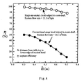
- Fig.8 shows the results of capture efficiencies by using a large upright board to simulate drafts generated by fan, air conditioner, or walk-by of people for both of the hood of the present invention and the conventional hood.
- Figs.9 is a schematic view showing another embodiment of the oblique single air curtain range hood of the present invention in use.
- Fig. 10 shows the oil collection device used in the hood of the present invention.
- Fig. 11 shows a cross sectional view of the connection of the oil collection device and the hood of the present invention.
- Fig. 12 shows a conventional range hood.
- Fig. 13 shows the non-dimensional upward velocity on central axis under hood opening when tested by laser Doppler velocimeter.
- Fig. 14 shows the capture zone of a conventional hood subject to influence of cross draft when tested by laser Doppler velocimeter.
- Fig. 15 shows the conventional range hood with left, right and front upward-blowing jets.
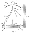
- Figs. 1A-1C show the hand sketches of the simplified flow fields associated to a planar jet, a suction slot, and a combination of the jet and the suction slot, respectively.
- a jet 50 is ejected from a nozzle 51 from the left to the right.
- the jet 50 therefore will expand outward in the downstream area.
- the fashion of expansion will depend on the characteristic regimes of Reynolds number. Downstream the nozzle 51 within a distance about 80 nozzle diameters, the momentum conservation is usually observed.
- the jet may expand, break up and disperse quickly after a distance about 100 ⁇ 150 nozzle diameters downstream the nozzle 51.
- a suction slot 53 draws air from the left to the right.
- the air flows around the suction slot 53 are denoted by reference 52.
- the active suction area is located within a downstream distance from the suction slot 53 to about only 1.5 times diameters of the suction slot 53, as mentioned previously.
- Individual use of the jet usually leads to early dispersion and individual use of the suction slot usually leads to poor suction capability at the distance beyond the effective suction range.
- a preferable embodiment of the pollutant removing device of the present invention comprises an air blow device 6 and a suction device 61 and the back thereof is adjacent to a wall 69.
- the air blow device 6 is provided with an elongate air blow slot 63 that is located in front of the pollutant discharge outlet 64 of a counter top 6' and through which air is blown upward.
- the suction device 61 is located above the counter top 6' and includes an elongate suction opening 60.
- the elongate suction opening 60 forms a suction port facing downward and is connected with a suction machine (not shown in this figure) for drawing in air.
- the elongate suction opening 60 is parallel to the elongate air blow slot 63 in a way that the elongate suction opening 60 is above and spaced from the elongate air blow slot 63 toward the wall.
- the elongate suction opening 60 can be formed by aligning plural suction holes.
- a rectangular suction device 61 is located at a distance from the counter top 6' and two curved flanges 62 extend from two sides of the elongate suction opening 60 of the suction device 61.
- the upward-blowing jets issued from the elongate air blow slot 63 located at the front end of the counter top 6' associated with the upward-drawing suction flow induced by the elongate suction opening 60 form the upward inclined air curtain 65 as shown in Figs.3 , so that the air between the air curtain 65 and the wall 69 can be pushed smoothly upward and vented outside through the elongate suction opening 60.
- the two sides above the counter top 6' are left open or equipped with grids or porous boards through which the compensation air can be naturally provided into the area between the oblique single air curtain 65 and the wall 69 as shown in Fig.3 , so that the air flows are steady.
- a flange 62 at one side of the elongate suction opening 60 extending toward the wall 69 can be a flat plate and one side of the flat plate is against the surface of the wall.
- the flange 62 can also include a fixing plate 621 and a telescopic plate 622 as shown in Fig.4 .
- the fixing plate 621 extends from one side of the elongate suction opening 60 toward the wall 69.
- the telescopic plate 622 is able to be extended or retracted relative to the fixing plate 621 to make the space between the suction device 61 and the wall 69 exposed or enclosed.
- the air is blown from the elongate air blow slot 63 in a direction 631 that is preferably toward the wall 69 and is tilted relative to the counter top at an angle of ⁇ °.
- another elongate air blow slot 66 can be provided at the back of the pollutant discharge outlet 64 of the counter top 6', that is, be provided between the elongate air blow slot 63 and the wall 69. Consequently, the two elongate air blow slots 63, 66 are provided at the front and the back of the pollutant discharge outlet 64 of the counter top 6' in a parallel manner and air can be blown upward through these slots 63, 66.
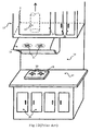
- an oblique single air curtain range hood which uses a pollutant removing device and the back of which is adjacent to a wall 82, is disclosed.
- the range hood comprises an air blow device 7 and a suction device 70.
- the air blow device 7 is provided with an elongate air blow slot 80 that is located in front of an oven 79 of a counter top 77 and air is blown upward through the elongate air blow slot 80.
- the suction device 70 is located above the counter top 77 and includes an elongate suction opening 81 that is connected with a suction machine 72.
- the elongate suction opening 81 is parallel to the elongate air blow slot 80 in a way that the elongate suction opening 81 is above and spaced from the elongate air blow slot 80 toward the wall.
- the elongate suction opening 81 can be a grid having plural suction holes.
- the suction device 70 includes an elongate suction opening 81 which forms a suction opening facing downward and two flanges 71 extend from two sides of the elongate suction opening 81.
- the suction device 70 is located at a certain height from a pedestal 78 so as to provide an upward suction force.
- the elongate suction opening 81 is connected with a suction machine 72 that is located in the cabinet 75 above the pedestal 78 so as to reduce noise.
- the pipe 721 is opened to outside of the room or is connected to a filter/oil-separation device/oil-collection device that brings the pollutant out of the room.
- two flanges 71 extend from the two sides of the elongate suction opening 81 of the suction device 70.
- the air blow device 7 is located at the front end of the ovens 79 of the pedestals 78 on the counter top 77.
- the air blow device 7 is an elongate air blow groove that is in communication with a blower and the blower is co-operated with the suction machine 72.
- the air blow device 7 also can be a cross flow fan that is co-operated with the suction machine 72 to form an upward-blowing air jet.
- an oblique single air curtain flow structure can be formed to prevent the pollutant from escaping from the capture area and effectively prevent the grease particles from attaching on the wall 82 at the back of the pedestal 78.
- the two sides above the counter top 77 are opened so that air can be sucked into the area between the single oblique air curtain and the wall to feed the suction action.
- the two sides above the counter top 77 may have porous boards or grids to allow the air be drawn into the area between the single oblique air curtain and the wall 82 with small flow resistance and vented outside through the elongate suction opening 81.
- the tracer gas method is used to examine the capture efficiencies of the present invention and the conventional range hood.
- the suction device is installed at different distances from the counter top and a large upright board swings at 0.35 m/s to simulate air flows generated by fan, or air conditioner or by people walking by the counter.
- Pure SF 6 gas is provided at constant flow rate by a gas releasing device placed on the counter top.
- the velocity and concentration of the SF 6 are detected at a remote cross section of the suction pipe.
- the capture efficiency which is defined as the flow rate of SF 6 passes through the suction pipe divided by the flow rate of pure SF 6 released from the gas releasing device, can be calculated.
- the result is disclosed in Fig. 8 .
- the single oblique air curtain range hood has much higher capture efficiency than that of the conventional range hood.
- the ability for reducing the interference by the reference flows of the range hood of the present invention is much higher than that of the conventional range hood.
- another elongate air blow slot 80' can be provided at the back of the oven 79 of the counter top 77, that is, provided between the elongate air blow slot 80 and the wall 82. Consequently, the two elongate air blow slots 80, 80' are provided at the front and the back of the oven 79 of the counter top 77 in a parallel manner and air can be blown upward through these slots 80, 80'.
- Figs.10 and 11 show an oil collection device 9 that is detachably connected to the elongate suction opening 81 of the suction device 70 so as to collect the oil flowing along insides of the elongate suction opening 81.
- the oil collection device 9 is a rectangular box with an open top and includes a base board 91 from which a first side panel 92, a first upright board 93, a second upright board 94 and a second side panel 95 extend upward.
- a filter 96 is connected to the base board 91.
- a first space 97 is defined between the first side panel 92, the first upright board 93 and the base board 91, and a second space 98 is defined between the second side panel 95, the second upright board 94 and the base board 91.
- Two support plates 99 are located above the filter 96 and connected between the first and second upright boards 93, 94.
- the first and second side panels 92, 95 are engaged with two outsides of the elongate suction opening 81.
- the oil mist may be condensed into grease particles and attach on the insides of the elongate suction opening 81.
- the condensed grease will flow along the insides of the suction device 70 by the effect of gravity and drop into the first and second spaces 97, 98.
- the grease collected in the first and second spaces 97, 98 can be cleaned by removing the oil collection device 9 from the elongate suction opening 81.
Landscapes
- Engineering & Computer Science (AREA)
- Chemical & Material Sciences (AREA)
- Combustion & Propulsion (AREA)
- Mechanical Engineering (AREA)
- General Engineering & Computer Science (AREA)
- Ventilation (AREA)
Priority Applications (1)
| Application Number | Priority Date | Filing Date | Title |
|---|---|---|---|
| EP08166293A EP2175204A1 (de) | 2008-10-09 | 2008-10-09 | Schadstoffentfernungsvorrichtung und Schrägvorhangsbereichkappe mit der Vorrichtung |
Applications Claiming Priority (1)
| Application Number | Priority Date | Filing Date | Title |
|---|---|---|---|
| EP08166293A EP2175204A1 (de) | 2008-10-09 | 2008-10-09 | Schadstoffentfernungsvorrichtung und Schrägvorhangsbereichkappe mit der Vorrichtung |
Publications (1)
| Publication Number | Publication Date |
|---|---|
| EP2175204A1 true EP2175204A1 (de) | 2010-04-14 |
Family
ID=40651521
Family Applications (1)
| Application Number | Title | Priority Date | Filing Date |
|---|---|---|---|
| EP08166293A Withdrawn EP2175204A1 (de) | 2008-10-09 | 2008-10-09 | Schadstoffentfernungsvorrichtung und Schrägvorhangsbereichkappe mit der Vorrichtung |
Country Status (1)
| Country | Link |
|---|---|
| EP (1) | EP2175204A1 (de) |
Cited By (7)
| Publication number | Priority date | Publication date | Assignee | Title |
|---|---|---|---|---|
| CN103791537A (zh) * | 2014-01-23 | 2014-05-14 | 广西华信恒基科技发展有限公司 | 厨房围型气帘装置 |
| CN105650706A (zh) * | 2016-03-28 | 2016-06-08 | 仲杏英 | 全封闭油烟机 |
| CN108224515A (zh) * | 2016-12-21 | 2018-06-29 | 九阳股份有限公司 | 一种油烟机柔性滤网自动换新控制方法及油烟机 |
| EP3358259A1 (de) | 2017-02-02 | 2018-08-08 | Electrolux Appliances Aktiebolag | Küchenanordnung |
| CN108488861A (zh) * | 2018-06-12 | 2018-09-04 | 黄书海 | 一种灶具和抽油烟机风幕换风系统 |
| CN108561925A (zh) * | 2018-06-19 | 2018-09-21 | 广东美的厨房电器制造有限公司 | 用于吸油烟机的冷凝板和吸油烟机 |
| CN111780178A (zh) * | 2020-06-08 | 2020-10-16 | 华帝股份有限公司 | 一种带涡流发生装置的吸油烟机 |
Citations (11)
| Publication number | Priority date | Publication date | Assignee | Title |
|---|---|---|---|---|
| NL7216603A (de) * | 1971-12-07 | 1973-06-12 | ||
| FR2506432A1 (fr) * | 1981-05-22 | 1982-11-26 | Noe Jacques | Unite d'apport d'air neuf a la peripherie d'un plan de cuisson |
| US4500331A (en) * | 1983-01-07 | 1985-02-19 | Cheng Chung Tsung | Kitchen exhaust apparatus |
| WO1998022755A1 (en) * | 1996-11-21 | 1998-05-28 | Kim Byong Duk | Ventilation device with air curtain effect |
| US6267112B1 (en) * | 2000-10-26 | 2001-07-31 | Pi Tang Chiang | Oil collection device for a kitchen range hood |
| DE20205642U1 (de) * | 2001-11-20 | 2002-07-25 | Maier, Max, 71636 Ludwigsburg | Dunstabsaugvorrichtung, insbesondere Dunstabzugshaube |
| US20030056784A1 (en) * | 2001-09-24 | 2003-03-27 | Peter Yeung | Range hood with grease collecting motor housing |
| US20040123860A1 (en) * | 2002-12-27 | 2004-07-01 | Jerome Lin | Gas stove deflecting air-wall structure |
| DE102005002156A1 (de) * | 2005-01-17 | 2006-07-20 | BSH Bosch und Siemens Hausgeräte GmbH | Küchendunstabzugsvorrichtung |
| EP1696180A2 (de) * | 2005-02-25 | 2006-08-30 | Waldner Labor- und Schuleinrichtungen GmbH | Absaugvorrichtung für eine Kocheinrichtung, insbesondere ein Kochfeld oder dergleichen |
| US20070256680A1 (en) * | 2006-05-03 | 2007-11-08 | Chi-Hsiung Chiang | Net device for smoke exhauster |
-
2008
- 2008-10-09 EP EP08166293A patent/EP2175204A1/de not_active Withdrawn
Patent Citations (11)
| Publication number | Priority date | Publication date | Assignee | Title |
|---|---|---|---|---|
| NL7216603A (de) * | 1971-12-07 | 1973-06-12 | ||
| FR2506432A1 (fr) * | 1981-05-22 | 1982-11-26 | Noe Jacques | Unite d'apport d'air neuf a la peripherie d'un plan de cuisson |
| US4500331A (en) * | 1983-01-07 | 1985-02-19 | Cheng Chung Tsung | Kitchen exhaust apparatus |
| WO1998022755A1 (en) * | 1996-11-21 | 1998-05-28 | Kim Byong Duk | Ventilation device with air curtain effect |
| US6267112B1 (en) * | 2000-10-26 | 2001-07-31 | Pi Tang Chiang | Oil collection device for a kitchen range hood |
| US20030056784A1 (en) * | 2001-09-24 | 2003-03-27 | Peter Yeung | Range hood with grease collecting motor housing |
| DE20205642U1 (de) * | 2001-11-20 | 2002-07-25 | Maier, Max, 71636 Ludwigsburg | Dunstabsaugvorrichtung, insbesondere Dunstabzugshaube |
| US20040123860A1 (en) * | 2002-12-27 | 2004-07-01 | Jerome Lin | Gas stove deflecting air-wall structure |
| DE102005002156A1 (de) * | 2005-01-17 | 2006-07-20 | BSH Bosch und Siemens Hausgeräte GmbH | Küchendunstabzugsvorrichtung |
| EP1696180A2 (de) * | 2005-02-25 | 2006-08-30 | Waldner Labor- und Schuleinrichtungen GmbH | Absaugvorrichtung für eine Kocheinrichtung, insbesondere ein Kochfeld oder dergleichen |
| US20070256680A1 (en) * | 2006-05-03 | 2007-11-08 | Chi-Hsiung Chiang | Net device for smoke exhauster |
Cited By (12)
| Publication number | Priority date | Publication date | Assignee | Title |
|---|---|---|---|---|
| CN103791537A (zh) * | 2014-01-23 | 2014-05-14 | 广西华信恒基科技发展有限公司 | 厨房围型气帘装置 |
| CN105650706A (zh) * | 2016-03-28 | 2016-06-08 | 仲杏英 | 全封闭油烟机 |
| CN105650706B (zh) * | 2016-03-28 | 2017-11-17 | 广东奥特龙电器制造有限公司 | 全封闭油烟机 |
| CN108224515A (zh) * | 2016-12-21 | 2018-06-29 | 九阳股份有限公司 | 一种油烟机柔性滤网自动换新控制方法及油烟机 |
| CN108224515B (zh) * | 2016-12-21 | 2019-12-06 | 九阳股份有限公司 | 一种油烟机柔性滤网自动换新控制方法及油烟机 |
| EP3358259A1 (de) | 2017-02-02 | 2018-08-08 | Electrolux Appliances Aktiebolag | Küchenanordnung |
| WO2018141536A1 (en) | 2017-02-02 | 2018-08-09 | Electrolux Appliances Aktiebolag | Kitchen assembly |
| CN110177978A (zh) * | 2017-02-02 | 2019-08-27 | 伊莱克斯家用电器股份公司 | 厨房组件 |
| CN108488861A (zh) * | 2018-06-12 | 2018-09-04 | 黄书海 | 一种灶具和抽油烟机风幕换风系统 |
| CN108488861B (zh) * | 2018-06-12 | 2024-05-28 | 黄书海 | 一种灶具和抽油烟机风幕换风系统 |
| CN108561925A (zh) * | 2018-06-19 | 2018-09-21 | 广东美的厨房电器制造有限公司 | 用于吸油烟机的冷凝板和吸油烟机 |
| CN111780178A (zh) * | 2020-06-08 | 2020-10-16 | 华帝股份有限公司 | 一种带涡流发生装置的吸油烟机 |
Similar Documents
| Publication | Publication Date | Title |
|---|---|---|
| US20100095949A1 (en) | Pollutant removing device and oblique single air curtain range hood using the device | |
| US20100000512A1 (en) | Pollutant Removing Device and Dual-Air Curtain Range Hood Using the Device | |
| EP2175204A1 (de) | Schadstoffentfernungsvorrichtung und Schrägvorhangsbereichkappe mit der Vorrichtung | |
| TWI408317B (zh) | 具有抗擾動氣流能力的排油煙機 | |
| KR101641389B1 (ko) | 배기 장치, 시스템, 및 포획력과 봉쇄력을 향상시키는 방법 | |
| AU2009205965B2 (en) | Hood devices, methods, and systems with features to enhance capture and containment | |
| US20070015449A1 (en) | Exhaust hood enhanced by configuration of flow jets | |
| EP1657494A1 (de) | Abzugshaube | |
| EP2138771B1 (de) | Schadstoffentfernungsvorrichtung und Dualluft-Vorhangsbereichkappe mit der Vorrichtung | |
| JP2001056142A (ja) | 台所用換気システム | |
| CN101598360B (zh) | 污染物排放装置及使用该装置的双气帘式排油烟机 | |
| KR20100045588A (ko) | 오염물질 제거 장치 및 상기 장치를 이용한 경사 단일 공기커튼 레인지 후드 | |
| JP2010007920A (ja) | 汚染物排出装置及び該装置を使用したツインエアカーテン式排煙装置 | |
| KR20100003806A (ko) | 오염물질 제거장치 및 그 장치를 이용한 이중-공기커튼랜지후드 | |
| CA2743409C (en) | Range hood capable of resisting draft | |
| JP2010107173A (ja) | 汚染物質排出装置およびその汚染物質排出装置を使用したエアカーテン式レンジフード | |
| TW201013124A (en) | A pollutant removing device and an oblique single air curtain range hood using the device | |
| TWI341916B (de) | ||
| CN101713559B (zh) | 污染物排放装置及使用该装置的斜向单气帘式排油烟机 | |
| TWM356084U (en) | Contaminant exhausting device and oblique single air-curtain type range hood using the same | |
| TWM392930U (en) | Frame with oblique jet flow | |
| TWM413824U (en) | Range hood having capability of resisting air flow disturbance |
Legal Events
| Date | Code | Title | Description |
|---|---|---|---|
| PUAI | Public reference made under article 153(3) epc to a published international application that has entered the european phase |
Free format text: ORIGINAL CODE: 0009012 |
|
| 17P | Request for examination filed |
Effective date: 20090911 |
|
| AK | Designated contracting states |
Kind code of ref document: A1 Designated state(s): AT BE BG CH CY CZ DE DK EE ES FI FR GB GR HR HU IE IS IT LI LT LU LV MC MT NL NO PL PT RO SE SI SK TR |
|
| AX | Request for extension of the european patent |
Extension state: AL BA MK RS |
|
| AKX | Designation fees paid |
Designated state(s): AT BE BG CH CY CZ DE DK EE ES FI FR GB GR HR HU IE IS IT LI LT LU LV MC MT NL NO PL PT RO SE SI SK TR |
|
| STAA | Information on the status of an ep patent application or granted ep patent |
Free format text: STATUS: THE APPLICATION IS DEEMED TO BE WITHDRAWN |
|
| 18D | Application deemed to be withdrawn |
Effective date: 20120113 |