EP2174576B1 - Appliance for conditioning a milk-based liquid - Google Patents
Appliance for conditioning a milk-based liquid Download PDFInfo
- Publication number
- EP2174576B1 EP2174576B1 EP09013396.8A EP09013396A EP2174576B1 EP 2174576 B1 EP2174576 B1 EP 2174576B1 EP 09013396 A EP09013396 A EP 09013396A EP 2174576 B1 EP2174576 B1 EP 2174576B1
- Authority
- EP
- European Patent Office
- Prior art keywords
- stirrer
- appliance
- tank
- stand
- milk
- Prior art date
- Legal status (The legal status is an assumption and is not a legal conclusion. Google has not performed a legal analysis and makes no representation as to the accuracy of the status listed.)
- Active
Links
Images


Classifications
-
- A—HUMAN NECESSITIES
- A47—FURNITURE; DOMESTIC ARTICLES OR APPLIANCES; COFFEE MILLS; SPICE MILLS; SUCTION CLEANERS IN GENERAL
- A47J—KITCHEN EQUIPMENT; COFFEE MILLS; SPICE MILLS; APPARATUS FOR MAKING BEVERAGES
- A47J27/00—Cooking-vessels
-
- A—HUMAN NECESSITIES
- A47—FURNITURE; DOMESTIC ARTICLES OR APPLIANCES; COFFEE MILLS; SPICE MILLS; SUCTION CLEANERS IN GENERAL
- A47J—KITCHEN EQUIPMENT; COFFEE MILLS; SPICE MILLS; APPARATUS FOR MAKING BEVERAGES
- A47J43/00—Implements for preparing or holding food, not provided for in other groups of this subclass
- A47J43/04—Machines for domestic use not covered elsewhere, e.g. for grinding, mixing, stirring, kneading, emulsifying, whipping or beating foodstuffs, e.g. power-driven
- A47J43/042—Mechanically-driven liquid shakers
-
- A—HUMAN NECESSITIES
- A47—FURNITURE; DOMESTIC ARTICLES OR APPLIANCES; COFFEE MILLS; SPICE MILLS; SUCTION CLEANERS IN GENERAL
- A47J—KITCHEN EQUIPMENT; COFFEE MILLS; SPICE MILLS; APPARATUS FOR MAKING BEVERAGES
- A47J27/00—Cooking-vessels
- A47J27/004—Cooking-vessels with integral electrical heating means
-
- A—HUMAN NECESSITIES
- A47—FURNITURE; DOMESTIC ARTICLES OR APPLIANCES; COFFEE MILLS; SPICE MILLS; SUCTION CLEANERS IN GENERAL
- A47J—KITCHEN EQUIPMENT; COFFEE MILLS; SPICE MILLS; APPARATUS FOR MAKING BEVERAGES
- A47J43/00—Implements for preparing or holding food, not provided for in other groups of this subclass
- A47J43/04—Machines for domestic use not covered elsewhere, e.g. for grinding, mixing, stirring, kneading, emulsifying, whipping or beating foodstuffs, e.g. power-driven
- A47J43/046—Machines for domestic use not covered elsewhere, e.g. for grinding, mixing, stirring, kneading, emulsifying, whipping or beating foodstuffs, e.g. power-driven with tools driven from the bottom side
- A47J43/0465—Machines for domestic use not covered elsewhere, e.g. for grinding, mixing, stirring, kneading, emulsifying, whipping or beating foodstuffs, e.g. power-driven with tools driven from the bottom side with magnetic drive
Definitions
- the present invention relates to an electric appliance for conditioning a milk-based liquid, in particular for heating and/or frothing such liquid, to be used for example in the context of the preparation of beverages such as cappuccinos, milky coffees, café latte and macchiato, chocolate and other hot or cold beverages.
- the best-known beverage of this type is a coffee of the cappuccino type. It comprises a liquid portion consisting of coffee topped by a layer of frothed milk which, because of its very much lower density, floats atop the surface of the liquid. In general, preparing one takes time, manipulation operations and cleaning.
- the most customary way of preparing a milk-based froth is to pour the desired amount of milk into the container, immerse a steam outlet pipe from a coffee machine in the container, agitating it up and down to introduce the air needed to form the froth.
- US Patent 6'318'247 relates to an appliance for preparing hot beverages or food with stirring such as hot chocolate, for example.
- the appliance comprises a system for driving a stirrer of the magnetic effect type. It does, however, have several disadvantages. Firstly, in such an appliance, the liquid or froth is stirred coaxially with respect to the central axis of the tank, and this causes a circulation in which some layers of liquid or froth, particularly the peripheral layers, are not stirred as extensively as others, particularly the layers near the middle, because of the centrifuging effect produced by the stirrer. Such a circulation is therefore not suited to producing a froth of sufficient quality or to reducing the time needed to produce this froth.
- the structure of the appliance is not hygienic for treating a milk-based liquid and cleaning is not made any easier by such a construction.
- Other devices for stirring food products which have more or less the same disadvantages are described in patent documents WO2004/043213 or DE 196 24 648 .
- Utility model DE 89 15 094 relates to a refrigerated pot for dispensing a milk-based beverage.
- the pot comprises refrigerating means and forced-convection means in the form of a magnetic rotor.
- Such a device is not suited to converting the liquid into a froth but simply keeps the liquid uniformly at the refrigeration temperature for preservation.
- US Patent 3,356,349 discloses a stirring device that has a heated tank, magnetic drive means positioned under the tank for driving a hub located in the middle of the tank.
- the hub is associated with a stirring element which is offset with respect to the hub, causing the element an oscillatory movement.
- Such a principle of stirring may create a loss in magnetic coupling because of the high moment of inertia generated by the offset position of the stirring means with respect to the axis of rotation of the drive means. This problem increases with increasing speed.
- Such a stirring device can therefore work to stir certain liquids or other substances at low speed but may prove ill-suited to converting liquid into a froth at sufficiently high speed.
- the document does not mention the conversion of a liquid into a froth using this device.
- the device has: a tank for receiving the liquid that is to be frothed, in which liquid a rotatable stirrer is positioned; a stand holding the tank; drive and control means which are in a cavity located between the inner tank and the outer stand, and which communicate with a switch and electrical connections located on the outer surface of the stand; and disturbance means to optimise circulation of the milk during frothing.
- This invention provides a solution to the abovementioned problems. It also recognises the hygiene issues that are raised the handling of milk, in particular heated milk that deposits against inner the walls of the tank.
- the device disclosed in the above publication has a tank for containing the milk which has no joining lines or connections between the tank's walls and generally no gaps that would attract the deposition of solids, such as burnt milk.
- Such a stirrer can for example be used in an appliance for conditioning milk or a milk-based liquid configured so that it can be properly washed with water, and optionally with a detergent and even in a dishwasher.
- this electric kitchen appliance i.e. not limiting cleaning of the external part by merely wiping its surface with a dry or humid towel like with prior art electric appliances
- the sensible parts of the appliance including the electric and electronic parts, are made water impervious in such a way that even the electric connections and interfaces that extend from the internal electric device through the appliance's housing, may be washed without damaging the appliance.
- the appliance may be safely washed, inside and outside, to remove any milk-based stains and spills so as to avoid any hygiene-related problems including on the external part of the appliance.
- the appliance is configured for conditioning a liquid made of or based on milk, in particular for preparing heated liquid or a cold or heated frothed liquid.
- the appliance may comprise: a tank for receiving the liquid that is to be conditioned; a closed compartment secured to the tank; and an electric device for imparting a conditioning effect to the liquid, which device is located in the compartment.
- the compartment can be made water impervious and washable under running water without infiltration thereof into the compartment containing the electric device.
- the appliance should be washable under running water by hand. Should the appliance also be washable in a dishwasher machine and/or using detergents, the exposed surfaces of the appliance should be made of detergent-resistant materials.
- the electric device has one or more connection means which extend through a through-opening in an outer wall of the compartment.
- such through-openings can be made water impervious by a sealing element (or gasket) located between a peripheral part of the connection means and the outer wall.
- a sealing element or gasket located between a peripheral part of the connection means and the outer wall.
- the sealing elements ensure water imperviousness, even when the appliance is thoroughly washed under running water, by hand or even in a dishwasher.
- the through-opening may be delimited by a surface of the compartment's wall, the delimitation surface extending from inside to outside the chamber and having a periphery.
- the sealing element may be located inbetween the peripheral part of the connection means and this delimitation surface and extend along the entire periphery of this delimitation surface around the connection means.
- the sealing member may advantageously fill any gap in the through-opening between the connection means and the wall through which the connection means extend.
- the sealing element is preferably deformable and compressed by and between the peripheral part of the connection means and this delimitation surface of the corresponding through-opening.
- connection means By having a deformed sealing member under permanent compression constraint and tension in the through-opening, i.e. expanding between the connection means and the facing wall, no infiltration passages are left or can be formed during use or handling for water to enter the chamber via the through-opening along the connection means.
- the sealing element is made of or comprises an elastic material, such as a silicon-based material or NBR.
- the sealing element may also comprise a plastic deformable material. The highest imperviousness is obtained when after deformation, the sealing member is compressed and remains under constraints between and against facing walls of the passage that is to be made impervious, i.e. that is to be sealed off to prevent water penetration.
- the sealing element can also be made of plastic and/or elastic material, such as silicone, that is cast between a peripheral part of said connection means and the outer wall.
- At least one connection means may comprise an electric conductor, in particular a copper and/or aluminium based conductor, for supplying electric power from a power supply to the electric device and/or for communicating a signal from and/or to the electric device.
- an electric conductor in particular a copper and/or aluminium based conductor, for supplying electric power from a power supply to the electric device and/or for communicating a signal from and/or to the electric device.
- the appliance can be connected directly via a cable to the mains (or data treatment unit).
- the cable may be permanently connected with the electric device or it may be linked via a plug and socket connection on the appliance to the electric device.
- the appliance has a cordless electrical connection assembly that is connectable to an electrical power supply base support to the mains (or data treatment unit). In any case, the imperviousness of the electric connection exiting the appliance's chamber must be ensured to avoid any water infiltration during washing. Further details relating to suitable cordless electrical connections are disclosed in the abovementioned W02006/050900 .
- the electric conductor may extend through a through-opening which contains a sealing element that is cast and/or deformed in compression between and by the conductor rod or cable and a wall's surface delimiting the through-opening.
- the sealing element is located in a cavity of the through-opening that extends transversally to the conductor rod or cable.
- the cavity may be partly covered on both sides, i.e. the cavity extending sideways within the wall, or only on one side of the wall. In the latter case, the cavity leads to a narrower aperture on one side of the wall and is entirely uncovered on the other side of the wall.
- connection means comprises or leads to a user interface for controlling the electric device.
- a user interface for controlling the electric device.
- Such interface may be a switch or a button or any means that is suitable for controlling the electric device contained in the appliance's chamber.
- a suitable button may extend into the through-opening.
- the button comprises a rigid support element, in particular a rigid annular element, which has a peripheral surface that faces the wall's surface delimiting the through-opening, the sealing element being compressed around the entire peripheral surface between and by said peripheral surface and said wall's surface.
- the sealing element is located and compressed between two facing rigid structures, the wall and the rigid support member.
- the button may be directly moulded on the rigid support element.
- the sealing element can be integral with or bonded to the button.
- the button, rigid support element and sealing element are formed as a unit that can be force-fitted into the through-opening, i.e. involving the compression of the sealing element, and possibly safely clipped inside the chamber to prevent any later unwanted dislodgement of the water-impervious sealed button.
- the button may comprise a movable member that extends through the through-opening, the support element being located around the movable member, the movable member being arranged to communicate into the compartment a user command by displacement of the movable member.
- the movable member can be movable in translation along the through-opening and/or in rotation, in particular about a rotational axis extending through the trough-opening or parallel thereto.
- the button can be a push button and/or a rotational button. For instance, the button may be pushed or rotated to provide different commands to the appliance, e.g. heating by pushing and stirring by rotating the button or vice versa.
- the electric device in the chamber may also have a timer function, preset or set by the user using an interface linked via a connection means to the appliance's electric device as outlined above.
- Control signals relating to the operation of the appliance may also be communicated via a connection means to an interface accessible by the user.
- the compartment is formed by the assembly of at least two casing parts, the casing parts being so assembled to be water impervious.
- At least one casing part is formed by at least a part of the tank, at least one further casing part being assembled with the tank to form with the tank, the impervious chamber containing the electric device.
- the tank for conditioning the liquid is located above the chamber and forms or delimits the upper part of the chamber.
- the chamber may be formed by a tubular member that holds in its upper inner part the tank and a bottom part that is integral or assembled therewith and that delimits the bottom of the chamber located under the tank.
- At least one casing part can be a lid or, as mentioned, a bottom element of the chamber.
- two such casing parts can be assembled together by welding to seal off the chamber.
- Two of such casing parts may have connection portions that are made of thermoplastic material and that are welded together, in particular by ultrasonic welding.
- two such casing parts can have connection portions that are made of a metal-based material and that are welded together.
- the casing parts can be assembled via a sealing element that seals off the chamber.
- the sealing element is elastic and/or plastic deformable and compressed by and between cooperating connection portions of the casing parts, as generally discussed above in relation with the through-openings.
- the casing parts have connection portions with substantially facing surfaces that compress the sealing element.
- the sealing element comprises: a body that extends over the surface of one connection portion and that is placed thereagainst; and a plurality of transverse members that protrude from said body to the surface of the facing connection portion and that are compressed between said body and the surface of the facing connection portion. Providing several transverse members that are individually compressed in the passage between the connection portions increases the reliability of the imperviousness of the sealing element. Such a configuration may be used for all deformable sealing elements used for the present purpose.
- a rigid support member may be secured to the connection portion of one of such casing parts to hold the cooperating connection portion of the other casing part, this cooperating connection portion being urged against the rigid support member by the compressed sealing element that is located and compressed between the cooperating connection portions.
- a first casing part can be mechanically secured or further secured to or against a second casing part by a mechanical assembly member, such as a screw or rivet, that extends through a through-opening in this first casing part, the through-opening being made water impervious by a sealing element located between a peripheral part of said mechanical assembly member and said first casing part.
- a mechanical assembly member such as a screw or rivet
- the appliance may comprise a rotatable stirrer for generating froth in the tank.
- the electric device in the chamber is then arranged to drive the stirrer in the tank, in particular by generating a rotating magnetic field in the chamber that drives the stirrer in the tank without any mechanical transmission element extending through the tank's walls between the electric device and the stirrer, the stirrer being removably mounted on a stirrer positioning element in the tank, such as a relief or recess in a bottom part of the tank.
- the electric device comprises heating means for heating the tank and a drive means for imparting a rotational movement to the stirrer located in the tank.
- the heating means and the drive means are operable independently from one another.
- the appliance also permits the frothing of such liquids without heating. It has been discovered that when a sufficient stirring is imparted to milk or a milk-based liquid an acceptable froth may be obtained even from a cold liquid. Therefore, the user is preferably given the possibility to stir the liquid with or without heating thereof.
- the invention concerns, in particular, a rotatable stirrer for an appliance as described above.
- the stirrer comprises: a positioning bottom part that is arranged to be removably mounted on said positioning element of the tank; and a peripheral part having stirring elements, such as turns of toroidally-shaped wire, impellers, blades, gratings or needles. Further details relating to suitable configurations of the bottom part and of this peripheral part can be found in WO2006/050900 .
- the stirrer further comprises a top part extending generally upright from this peripheral part.
- This top part has a holding portion that is arranged to accommodate for human fingers so as to facilitate extraction and insertion of said stirrer on said positioning element of the tank.
- Such a top part enabling enhanced gripping is particularly useful when the stirrer gets stuck on the bottom, for instance when milk product gets burnt or stick between the stirrer and the positioning element.
- the top part is generally in the shape of an arched member that forms generally an upright loop, optionally the loop forming generally a circle or a fraction of a circle (e.g. half a circle) extending upwards from adjacent opposite sides of the peripheral part.
- the top part forming a loop can further comprise an elongated upright member extending upwards from an upper end of the loop.
- Such an upright member is optionally topped with a laterally protruding element to facilitate seizure by human fingers, for example a spherical element.
- An electric device for an appliance as described above may comprise: a drive means for imparting a rotational movement to a stirrer associated therewith; and a heating means for heating a tank associated therewith.
- the heating means and the drive means may be operable independently from one another, as discussed above.
- the electric device can be associated with a user interface which is arranged to allow independent control of the drive means and of the heating means.
- the user interface may comprise a first button for controlling the drive means and a second button for controlling the heating means, or a single button with different positions for controlling the drive means and the heating means.
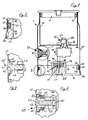
- FIG. 1 An appliance 1 for conditioning a liquid made of or based on milk, in particular for preparing heated liquid and/or a cold or heated frothed liquid with a stirrer according to the invention is shown in Figures 1 and 1a , Figures 2 and 3 showing enlarged views of parts A and B, respectively, of Figure 1 .
- Appliance 1 has a tank 10 for receiving the liquid that is to be conditioned, a closed compartment 20 located under tank 10; and an electric device 50 for imparting a conditioning effect to a liquid contained in tank 10.
- Electric device 50 is located in compartment 20.
- compartment 20 is made water impervious and washable with running water without infiltration thereof into the compartment 20 containing the electric device 50.
- compartment 20 is formed by a generally tubular stand 21 assembled to a rigid plastic bottom 30.
- the upper part of compartment 20 is delimited by tank 10 which is located inside and secured to stand 21.
- tubular stand 21, bottom 30 and tank 10 are three casing parts, which when assembled, form together chamber 20.
- Tank 10 and stand 21 are made of metal and welded together at there upper end so that the assembly of the two parts is made water impervious as extensively discussed above.
- Bottom 30 is made of rigid material, such as rigid plastic material.
- Tank 10 is covered with a removable lid 11, typically made of plastic, that has a peripheral sealing ring 12.
- bottom 30 has an upright peripheral wall 31 facing the inner bottom end of tubular stand 21.
- Wall 31 has a peripheral groove 32 that faces stand 21 and that extends around the entire bottom 30.
- a peripheral sealing ring 33 (e.g. an o-ring type gasket) located in groove 32 extends around the entire wall 31.
- Sealing ring 33 is made of elastic deformable material such as NBR. Ring 33 is squeezed and compressed in groove 32 by the inner bottom end of stand 21 that urges ring 33 into groove 32, especially against the groove's surface 34 facing bottom end of stand 21 and substantially parallel thereto.
- compressed sealing ring 33 seals off any gap or passage between stand 21 and bottom 30, so that no water infiltration may occur between stand 21 and bottom 30 during washing, by hand or even in a dishwasher.
- the bottom end 22 of tubular stand 21 is slightly angled out and the upper end of upright bottom wall 31 has a bevel 35 to facilitate the introduction of bottom 30 into stand 21.
- bottom 30 may be permanently clipped in stand 21,
- bottom 30 includes a plurality of clips 90 arranged spaced apart around a peripheral part of bottom 30.
- Each clip 90 has a pair of generally upright fingers 91,92 with upper hooks 93 and a central rod-shaped abutment member 94 that are arranged for engaging, by clipping, with a corresponding hanger 95 that has a support member 96 mechanically secured, e.g. by welding, against the inner side of stand 21.
- appliance 1 is of the cordless type and intended to be removably placed and powered by an electric base unit 2 that may be connected to the mains via an electric cable 3, as illustrate in Figure 1a .
- bottom 30 includes a plurality of cordless connector pins 51, one of which is shown in Figure 1 , that are connected to electric device 50 and that are made of an electrically highly conductive material typically metal, such as copper or aluminium or an alloy based thereon.
- Connector pins 51 extend from inside to outside chamber 20 through a through-opening or passage 36 in bottom 30 for connecting electric device 50 to external base unit 2.
- Trough-opening or passage 36 is so arranged as to be water-impervious.
- Trough-opening or passage 36 includes a top aperture 37 leading into chamber 20, a lower aperture 37' leading outside chamber 20 and an intermediate cavity containing a sealing element 38 between upright walls 39 of bottom 30.
- the sealing member 38 is made of elastic material, such as silicone that is directly cast around connector pin 51 into the intermediate cavity between upright walls 39 and pin 51 so as to firmly adhere to pin 51 and the surfaces of the cavity, in particular of walls 39, and thus render the intermediate cavity of through-opening or passage 36 water impervious.
- pin 51 comprises an abutment 52 adjacent lower aperture 37' to avoid displacement of pin 51 in through-opening or passage 36.
- pins 51 are associated with vertical walls 39' that delimit in combination with walls 39 and pins 51 grooves for mounting appliance 1 onto base unit 2 that will support and provide electrical power to the cordless appliance 1. Details of such cordless connectors are for example disclosed in WO2006/050900 and the references cited therein.
- appliance 1 comprises a plurality of pushbuttons 60, one of which is shown in Figure 1 and in Figure 2 that shows an enlarged view of portion A of Figure 1 , for controlling electric device 50 from outside appliance 1.
- Push-button 60 extends into chamber 20 through a through-opening in stand 21.
- Button 60 has a core 61 made of elastic material mounted or injected or cast onto on a rigid ring 67 made of metal, ceramic, hard plastic and/or another hard material.
- Core 61 comprises a button head 62 which can be pushed by the user, and a movement transmission rod 63 integral therewith.
- Button head 62 is integral with a peripheral sealing element 64 and connected therewith via elastic deformable hinge 65 integral with sealing element 64 and button head 62.
- sealing element 64 is deformed in compression between rigid ring 67 and a (rigid) portion 23 of stand 21.
- Portion 23 delimits the through-opening that houses push-button 60 and has a surface that faces and is substantially parallel to the surface of rigid ring 67, these two surfaces squeezing sealing element 64 making the through-opening for button 60 water impervious.
- sealing element 64 has a bevelled arrow-like end portion that extends transversally 66 for facilitating the insertion of button 60 into the through-opening and permanently clipping button 60 in stand 21 so as to avoid any displacement or misplacement thereof that would impair the water-imperviousness.
- rod 63 of button 60 extends inside chamber 20 between guide members 53 towards a contact element 55 that is connected with electric device 50 and that can be operated by pressing button head 62 and transmission rod 63 thereagainst, thereby deforming hinge 65.
- FIG. 2a in which the same numeric references designate the same elements, shows another button arrangement.
- Push-button 60'' is secured in a through-opening delimited by a rigid wall portion 23 of stand 21 using a rigid annular clipping arrangement 67'.
- Clipping arrangement 67' has an annular neck 67a which extends along sealing ring 64 and which urges sealing ring 64 against an outside surface 23b of wall 23.
- Annular neck 67a is formed by a series of spaced apart clipping fingers, one of which is shown in the lower part of Figure 2a , having an arm 67a with a hook 67b, a bevel 67d, an end 67e extending over the edge of wall portion 23 and a circular flange 67c extending over a ledge 23a of wall portion 23.
- Flange 67c is covered with a peripheral extension 65a of the button's elastic hinge 65.
- Sealing ring 64 is connected to button head 62 via connecting portions 64a that extend between the roots of arms 67a which roots join arms 67a to circular flange 67c.
- Each clipping finger is slightly resilient and has a bevel 27d to allow insertion of the annular clipping arrangement 67' into the through-opening delimited by wall portion 23 up to ledge 23 and for clipping hook 67b over the edge of wall portion 23.
- button head 62 is assembled to a movement transmission hard rod 63' whose end 63" is arranged to push contact element 55 when button-head 62 is pressed by a user.
- Figure 4 in which the same numeric references designate the same elements, shows an arrangement of a comparative prior art button 60'. Similar buttons are disclosed in the abovementioned WO2006/050900 .
- Button 60' is secured in a through-opening extending through stand 21 by an a peripheral integral part 64' of button 60' that is clipped on edge 23' of stand 21, edge 23' delimiting the through-opening for button 60'.
- the peripheral integral part 64' is not urged and compressed against edge 23'.
- This integral part 64' does not firmly obstruct the passage along button 60' into chamber 20, and therefore no water-impervious sealing can be provided, especially when button 60' is pressed, causing a flexion and displacement of peripheral part 64' around edge 23'. This is all the more problematic when the button is exposed to milk spills that may infiltrate chamber 20 and durably soil the electric part of the appliance.
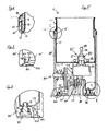
- FIGs 5 in which the same numeric references designate the same elements, shows another appliance 1 and stirrer according to the invention. Appliance 1 is shown without lid on tank 10. As opposed to prior art appliances splashes of milk on the external parts of the appliance in not problematic anymore, so that the appliance can be operated without lid, giving the user access to the liquid during the conditioning treatment.
- tubular stand 21' is made of a material, typically a plastic material, that cannot be welded to the material of tank 10, typically a metal-based material. Nevertheless, to ensure water-imperviousness of the assembly of stand 21' and tank 10 located therein, a peripheral sealing element 15 is used along the entire junction between tank 10 and stand 21', i.e. around the entire tank 10. Sealing element 15 is made of elastic material such as NBR and is permanently compressed between tank 10 and stand 21'.
- sealing element 15 has a body 16 that extends over a portion of the surface of tank 10 and that is placed thereagainst; and three peripheral transverse members 17 that protrude from body 16 to the inner surface of the upper end of stand 21'.
- the peripheral transverse members 17 extend along body 16 around the entire tank 10.
- the inner surface of stand 21' faces and is generally parallel to said surface of tank 10. These two surfaces compress the transverse members 17 and body 16 of sealing element 15 that is located between these surfaces.
- sealing element 64 securing push-button 60 in the through-opening in stand 21 has similar peripheral transverse members that are compressed against portion 23 of stand 21.
- tank 10 is associated with a down-coming peripheral rigid support member 10' that extends along tank 10 with a lower part 10'' that is angled away from tank.
- the rigid support member 10', 10'' helps to position and secure tank 10 on stand 21'.
- Support member 10',10" urges stand 21' against sealing member 15 and tank 10 and, at the same time, stands on a shoulder 23 of stand 21' to secure tank 10 on stand 21'.
- Sealing element 15 further comprises at its upper end flexible transverse member 18 that seals off the gap between tank 10 and the lower part 10" angling away therefrom.
- Appliance 1 has a bottom 30' that is connected to stand 21' by ultrasonic welding.
- Stand 21' and bottom 30' are, at least where they are welded together, of thermoplastic materials that are compatible for the purpose of welding.
- bottom 30' has two parallel upright peripheral walls 301,302 that delimit thereinbetween a peripheral groove 303. These walls 301,302 and groove 303 extend along the entire periphery of bottom 30'.
- the bottom part of stand 21' has a generally angled, in particular right-angled connecting member 25 protruding from the inner surface of the bottom part of stand 21', extending along the entire inner surface of stand 21', thereby forming an inner loop over the peripheral part of bottom 30', and having an end portion 26 shaped to accommodate into the groove 303.
- connecting member 25 and bottom 30' are assembled with the help of an ultrasound welder that causes superficial melting of the surfaces of end portion 26 which, during the welding process, come into contact with correspondingly melting surfaces of peripheral walls 301,302.
- Such welding provides a perfectly water-impervious bond between stand 21' and bottom 30'.
- Screw 70 can be used to further secure bottom 30' in appliance 1.
- screw 70 extends through a through-opening in bottom 30'.
- This through-opening is made water impervious by a sealing ring (e.g. an o-ring type gasket) 71 that is fitted around screw 70 and that is compressed between screw 70 and the facing walls delimiting the through-opening.
- a sealing ring e.g. an o-ring type gasket
- the bottom part of tank 10 is welded, or otherwise connected, to feet 13, one of which is shown in Figures 5 and 8 , that extend down along stand 21' to bottom 30' and are provided with a threaded hole 14 for securing screw 70 therein.
- tanks 10 shown in Figures 1 and 5 are provided with a stirrer positioning element 80 for a stirrer 85, 85' which is removably mounted thereon.
- Stirrer 85,85' includes a peripheral part having stirring elements 86, such as turns of toroidally-shaped wire, impellers, blades, gratings or needles.
- stirring elements 86 such as turns of toroidally-shaped wire, impellers, blades, gratings or needles.
- Suitable drive means and configuration of the rotating stirrer, in particular the magnetic transmission arrangement between the electric device in the chamber and the stirrer in the tank, are disclosed in greater details in the abovementioned WO2006/050900 .
- stirrers 85,85' have a top part 87,88,89 extending generally upright from peripheral part 86.
- This top part has a holding portion 87,88,89 that is arranged to accommodate for human fingers so as to facilitate extraction and insertion of stirrer 85,85' on the positioning element 80 of the tank 10.
- the top part 87,88,89 includes a generally semi-circular arched member 87.
- stirrer 85' depicted in Figure 5 further comprises an elongated upright rod 88 extending upwards from an upper end of the arched member 87.
- upright rod 88 is topped with a laterally protruding generally spherical element 89 to facilitate seizure by human fingers.
- FIGS 9 and 10 in which the same numeric references designate the same elements, show stirrer 85 in greater detail.
- Stirring element 86 is in the form of a spring element in a loop arranged on a ring 86' that is secured via second connecting member 87c to a support member 87a.
- Arched member 87 is secured to support member 87a via first connecting members 87b.
- support member 87a has a through-opening D for the passage of stirrer positioning element 80.
- Arched member 87 which is shown in cross-section in Figure 10 , and connecting members 87b have a convex outer surface 87' and optionally a concave or straight inner surface 87". Without being bound to any theory, it is believed that that such a cross-section promotes the generation of cavitations during rotation of stirrer 85 in a liquid such as milk, especially nearby connecting members 87b that are subjected to the greatest tangential speed during rotation, leading to the formations of fine bubbles and an improved foaming of the liquid.
- FIG 11 shows another embodiment of a stirrer 85'' of the invention.
- stirrer 85'' instead of having a spring stirring element like in Figure 9 , has two blade-like elements 86''.
- the arched member of the stirrer can have a generally parabolic, semi-elliptic or tapered shape or like shape, instead of a semi-circular shape.
- the appliances are fitted with heating elements that are connected to electric device 50. Details of suitable heating elements are described in greater details in the abovementioned W02006/050900 .
- Heating element 56 and stirrer 85,85' may be controlled via push buttons 60 by the user.
- a stirrer may be associated with one or more buttons, for instance when the user is given the possibility to choose among several rotating speeds of the stirrer. Likewise, several buttons may be provided to choose a desired heating temperature. It will be apparent to the skilled person that many variations are possible to select and configure the control means so as to allow the user to choose, for example a desired heating temperature, stirring speed and conditioning duration and conditioning profile.
Description
- The present invention relates to an electric appliance for conditioning a milk-based liquid, in particular for heating and/or frothing such liquid, to be used for example in the context of the preparation of beverages such as cappuccinos, milky coffees, café latte and macchiato, chocolate and other hot or cold beverages.
- Speciality beverages in which at least a portion is made up of frothed or heated milk are becoming more and more popular. The best-known beverage of this type is a coffee of the cappuccino type. It comprises a liquid portion consisting of coffee topped by a layer of frothed milk which, because of its very much lower density, floats atop the surface of the liquid. In general, preparing one takes time, manipulation operations and cleaning.
- The most customary way of preparing a milk-based froth is to pour the desired amount of milk into the container, immerse a steam outlet pipe from a coffee machine in the container, agitating it up and down to introduce the air needed to form the froth.
- There also exists mechanical stirring appliances which are usually intended for domestic use for beating froth from more or less viscous food products such as eggs, ice, juices or the like. The problem with these appliances is of several natures which means that they are ill-suited to producing froth from a milk-based liquid for making a beverage. One disadvantage, for example, stems from the fact that these appliances stir a liquid or a paste in the cold state, considerably limiting their potential use. In addition, milk does not froth as convincingly when cold or at ambient temperature.
- Another disadvantage stems from the fact that these appliances are ill-suited to frothing the microbiologically sensitive liquids such as milk. Regular cleaning of the tank of the appliance needs to be envisaged in order to remove any solid food residue. In addition, heating the milk has a tendency to increase the extent to which cooked or burnt proteins are deposited on and adhere to the surfaces. The existing appliances are not, for the most part, well suited to reducing the encrustation of this solid residue, making cleaning troublesome.
- These appliances also have a stirring and drive mechanism which is fixed and intrudes into the tank, and this presents several disadvantages: the removal/refitting time is not insignificant, they have a tendency to become soiled more quickly, they entail additional cost as a result of the multiplicity of components, and the stirring means are difficult to clean.
- Another disadvantage with these appliances stems from the fact that frothing in these appliances is not optimal for reasons associated with the arrangement of the stirring means. Some appliances have a stirring means positioned in the middle of the tank. Such an arrangement is not efficient in quickly converting a volume of milk-based liquid into a rich froth.
- Other appliances have several stirrers. These arrangements are generally mechanical with gearing means needed to coordinate the rotation of the stirrers, and this makes the system intrusive, and therefore less hygienic, increases the number of parts and makes cleaning a more painstaking operation.
- US Patent 6'318'247 relates to an appliance for preparing hot beverages or food with stirring such as hot chocolate, for example. The appliance comprises a system for driving a stirrer of the magnetic effect type. It does, however, have several disadvantages. Firstly, in such an appliance, the liquid or froth is stirred coaxially with respect to the central axis of the tank, and this causes a circulation in which some layers of liquid or froth, particularly the peripheral layers, are not stirred as extensively as others, particularly the layers near the middle, because of the centrifuging effect produced by the stirrer. Such a circulation is therefore not suited to producing a froth of sufficient quality or to reducing the time needed to produce this froth. In addition, the structure of the appliance is not hygienic for treating a milk-based liquid and cleaning is not made any easier by such a construction. Other devices for stirring food products which have more or less the same disadvantages are described in patent documents
WO2004/043213 orDE 196 24 648 . - Stirring systems with a magnetic engagement type are described in documents
US 2 932 493 ,DE 1 131 372US 4 537 332 andUS 6 712 497 but none of these provide solutions suited to producing a quality froth in a short time and hygienically. - Utility model
DE 89 15 094 relates to a refrigerated pot for dispensing a milk-based beverage. The pot comprises refrigerating means and forced-convection means in the form of a magnetic rotor. Such a device is not suited to converting the liquid into a froth but simply keeps the liquid uniformly at the refrigeration temperature for preservation. -
US Patent 3,356,349 discloses a stirring device that has a heated tank, magnetic drive means positioned under the tank for driving a hub located in the middle of the tank. The hub is associated with a stirring element which is offset with respect to the hub, causing the element an oscillatory movement. Such a principle of stirring may create a loss in magnetic coupling because of the high moment of inertia generated by the offset position of the stirring means with respect to the axis of rotation of the drive means. This problem increases with increasing speed. Such a stirring device can therefore work to stir certain liquids or other substances at low speed but may prove ill-suited to converting liquid into a froth at sufficiently high speed. Incidentally, the document does not mention the conversion of a liquid into a froth using this device. - More recently, an improved appliance for preparing froth from a milk-based liquid or milk has been proposed in
WO2006/050900 . The device has: a tank for receiving the liquid that is to be frothed, in which liquid a rotatable stirrer is positioned; a stand holding the tank; drive and control means which are in a cavity located between the inner tank and the outer stand, and which communicate with a switch and electrical connections located on the outer surface of the stand; and disturbance means to optimise circulation of the milk during frothing. This invention provides a solution to the abovementioned problems. It also recognises the hygiene issues that are raised the handling of milk, in particular heated milk that deposits against inner the walls of the tank. Hence, the device disclosed in the above publication has a tank for containing the milk which has no joining lines or connections between the tank's walls and generally no gaps that would attract the deposition of solids, such as burnt milk. - However, despite the recent hygiene-related improvements regarding the preparation of the froth, it has been found that while the apparatus is handled by users, in particular un-cautious handling of the apparatus, for example when frothed milk is removed from the tank, milk may spill and stain the stand and other external parts and raise hygiene problems. The same problems may arise due to presence of the disturbance means that induce and increase agitation in the liquid and thus splashing. This problem is particularly acute in relation with switches, electrical connections and other parts of the stand that may attract milk deposits over time and cause cleaning problems and are in addition hard to clean properly without damaging the electric appliance. One way to solve this problem, at least in part, may involve the use of an appropriate lid and dispensing arrangement configured to avoid spills on the outer part of the appliance. This would however still require special attention by the user to avoid such spills.
- It is therefore an object of the invention to alleviate the disadvantages of the prior art by proposing an appliance better suited for the production of froth from a milk-based food liquid.
- This object is generally achieved by providing a stirrer as defined in
claim 1. - Such a stirrer can for example be used in an appliance for conditioning milk or a milk-based liquid configured so that it can be properly washed with water, and optionally with a detergent and even in a dishwasher. In order to render this electric kitchen appliance properly washable, i.e. not limiting cleaning of the external part by merely wiping its surface with a dry or humid towel like with prior art electric appliances, the sensible parts of the appliance, including the electric and electronic parts, are made water impervious in such a way that even the electric connections and interfaces that extend from the internal electric device through the appliance's housing, may be washed without damaging the appliance. Hence, the appliance may be safely washed, inside and outside, to remove any milk-based stains and spills so as to avoid any hygiene-related problems including on the external part of the appliance.
- For instance, the appliance is configured for conditioning a liquid made of or based on milk, in particular for preparing heated liquid or a cold or heated frothed liquid. The appliance may comprise: a tank for receiving the liquid that is to be conditioned; a closed compartment secured to the tank; and an electric device for imparting a conditioning effect to the liquid, which device is located in the compartment. The compartment can be made water impervious and washable under running water without infiltration thereof into the compartment containing the electric device.
- In other words, all passages leading from outside to inside the compartment, whether they result for example from the assembly of the appliance or whether they are for instance used for connecting the inner part of the compartment to its external part, which passages would allow water infiltration into the compartment, are sealed off.
- In any case, the appliance should be washable under running water by hand. Should the appliance also be washable in a dishwasher machine and/or using detergents, the exposed surfaces of the appliance should be made of detergent-resistant materials.
- Usually, the electric device has one or more connection means which extend through a through-opening in an outer wall of the compartment. Typically, such through-openings can be made water impervious by a sealing element (or gasket) located between a peripheral part of the connection means and the outer wall. In contrast to prior art deformable covering parts that merely extend over opening in the housing and that can easily be moved away or torn away into such a position as to allow water infiltration through the opening into the inner part of the appliance during normal handling of the appliance, the sealing elements ensure water imperviousness, even when the appliance is thoroughly washed under running water, by hand or even in a dishwasher.
- The through-opening may be delimited by a surface of the compartment's wall, the delimitation surface extending from inside to outside the chamber and having a periphery. In such a case, the sealing element may be located inbetween the peripheral part of the connection means and this delimitation surface and extend along the entire periphery of this delimitation surface around the connection means. In other words, the sealing member may advantageously fill any gap in the through-opening between the connection means and the wall through which the connection means extend. To improve the water-imperviousness of this arrangement, the sealing element is preferably deformable and compressed by and between the peripheral part of the connection means and this delimitation surface of the corresponding through-opening. By having a deformed sealing member under permanent compression constraint and tension in the through-opening, i.e. expanding between the connection means and the facing wall, no infiltration passages are left or can be formed during use or handling for water to enter the chamber via the through-opening along the connection means.
- Typically, the sealing element is made of or comprises an elastic material, such as a silicon-based material or NBR. The sealing element may also comprise a plastic deformable material. The highest imperviousness is obtained when after deformation, the sealing member is compressed and remains under constraints between and against facing walls of the passage that is to be made impervious, i.e. that is to be sealed off to prevent water penetration. The sealing element can also be made of plastic and/or elastic material, such as silicone, that is cast between a peripheral part of said connection means and the outer wall.
- At least one connection means may comprise an electric conductor, in particular a copper and/or aluminium based conductor, for supplying electric power from a power supply to the electric device and/or for communicating a signal from and/or to the electric device.
- There are different possibilities to supply electrical power to the appliance (or exchange electric data to and from the appliance's electric device). For example, the appliance can be connected directly via a cable to the mains (or data treatment unit). The cable may be permanently connected with the electric device or it may be linked via a plug and socket connection on the appliance to the electric device. Alternatively, the appliance has a cordless electrical connection assembly that is connectable to an electrical power supply base support to the mains (or data treatment unit). In any case, the imperviousness of the electric connection exiting the appliance's chamber must be ensured to avoid any water infiltration during washing. Further details relating to suitable cordless electrical connections are disclosed in the abovementioned
W02006/050900 . - As mentioned above, the electric conductor may extend through a through-opening which contains a sealing element that is cast and/or deformed in compression between and by the conductor rod or cable and a wall's surface delimiting the through-opening. Optionally, The sealing element is located in a cavity of the through-opening that extends transversally to the conductor rod or cable. The cavity may be partly covered on both sides, i.e. the cavity extending sideways within the wall, or only on one side of the wall. In the latter case, the cavity leads to a narrower aperture on one side of the wall and is entirely uncovered on the other side of the wall.
- Typically, at least one connection means comprises or leads to a user interface for controlling the electric device. Such interface may be a switch or a button or any means that is suitable for controlling the electric device contained in the appliance's chamber.
- A suitable button may extend into the through-opening. For instance, the button comprises a rigid support element, in particular a rigid annular element, which has a peripheral surface that faces the wall's surface delimiting the through-opening, the sealing element being compressed around the entire peripheral surface between and by said peripheral surface and said wall's surface. In such a case, the sealing element is located and compressed between two facing rigid structures, the wall and the rigid support member. To simplify the manufacture, the button may be directly moulded on the rigid support element. Moreover, the sealing element can be integral with or bonded to the button. In an advantageous configuration, the button, rigid support element and sealing element are formed as a unit that can be force-fitted into the through-opening, i.e. involving the compression of the sealing element, and possibly safely clipped inside the chamber to prevent any later unwanted dislodgement of the water-impervious sealed button.
- The button may comprise a movable member that extends through the through-opening, the support element being located around the movable member, the movable member being arranged to communicate into the compartment a user command by displacement of the movable member. The movable member can be movable in translation along the through-opening and/or in rotation, in particular about a rotational axis extending through the trough-opening or parallel thereto. In any case, the button can be a push button and/or a rotational button. For instance, the button may be pushed or rotated to provide different commands to the appliance, e.g. heating by pushing and stirring by rotating the button or vice versa.
- Likewise, the electric device in the chamber may also have a timer function, preset or set by the user using an interface linked via a connection means to the appliance's electric device as outlined above. Control signals relating to the operation of the appliance may also be communicated via a connection means to an interface accessible by the user.
- Typically, the compartment is formed by the assembly of at least two casing parts, the casing parts being so assembled to be water impervious.
- In an embodiment, at least one casing part is formed by at least a part of the tank, at least one further casing part being assembled with the tank to form with the tank, the impervious chamber containing the electric device. For example, the tank for conditioning the liquid is located above the chamber and forms or delimits the upper part of the chamber. The chamber may be formed by a tubular member that holds in its upper inner part the tank and a bottom part that is integral or assembled therewith and that delimits the bottom of the chamber located under the tank. At least one casing part can be a lid or, as mentioned, a bottom element of the chamber.
- To ensure water imperviousness, two such casing parts can be assembled together by welding to seal off the chamber. Two of such casing parts may have connection portions that are made of thermoplastic material and that are welded together, in particular by ultrasonic welding. Moreover, two such casing parts can have connection portions that are made of a metal-based material and that are welded together.
- When welding is not desired or not possible, for instance because of the specific material combination, the casing parts can be assembled via a sealing element that seals off the chamber. Usually, the sealing element is elastic and/or plastic deformable and compressed by and between cooperating connection portions of the casing parts, as generally discussed above in relation with the through-openings.
- Typically, the casing parts have connection portions with substantially facing surfaces that compress the sealing element.
- In one embodiment, the sealing element comprises: a body that extends over the surface of one connection portion and that is placed thereagainst; and a plurality of transverse members that protrude from said body to the surface of the facing connection portion and that are compressed between said body and the surface of the facing connection portion. Providing several transverse members that are individually compressed in the passage between the connection portions increases the reliability of the imperviousness of the sealing element. Such a configuration may be used for all deformable sealing elements used for the present purpose.
- A rigid support member may be secured to the connection portion of one of such casing parts to hold the cooperating connection portion of the other casing part, this cooperating connection portion being urged against the rigid support member by the compressed sealing element that is located and compressed between the cooperating connection portions.
- Furthermore, a first casing part can be mechanically secured or further secured to or against a second casing part by a mechanical assembly member, such as a screw or rivet, that extends through a through-opening in this first casing part, the through-opening being made water impervious by a sealing element located between a peripheral part of said mechanical assembly member and said first casing part. The particular arrangement of the sealing member can be achieved in a similar manner like for the above discussed connection means.
- The appliance may comprise a rotatable stirrer for generating froth in the tank. The electric device in the chamber is then arranged to drive the stirrer in the tank, in particular by generating a rotating magnetic field in the chamber that drives the stirrer in the tank without any mechanical transmission element extending through the tank's walls between the electric device and the stirrer, the stirrer being removably mounted on a stirrer positioning element in the tank, such as a relief or recess in a bottom part of the tank.
- Usually the electric device comprises heating means for heating the tank and a drive means for imparting a rotational movement to the stirrer located in the tank.
- Further details of suitable drive means and heating means are described in
WO2006/050900 . - In an advantageous embodiment, the heating means and the drive means are operable independently from one another. In addition to providing the option of heating milk or the milk-based liquid without frothing it, the appliance also permits the frothing of such liquids without heating. It has been discovered that when a sufficient stirring is imparted to milk or a milk-based liquid an acceptable froth may be obtained even from a cold liquid. Therefore, the user is preferably given the possibility to stir the liquid with or without heating thereof.
- The invention concerns, in particular, a rotatable stirrer for an appliance as described above. The stirrer comprises: a positioning bottom part that is arranged to be removably mounted on said positioning element of the tank; and a peripheral part having stirring elements, such as turns of toroidally-shaped wire, impellers, blades, gratings or needles. Further details relating to suitable configurations of the bottom part and of this peripheral part can be found in
WO2006/050900 . - In accordance with the invention, the stirrer further comprises a top part extending generally upright from this peripheral part. This top part has a holding portion that is arranged to accommodate for human fingers so as to facilitate extraction and insertion of said stirrer on said positioning element of the tank.
- Such a top part enabling enhanced gripping, is particularly useful when the stirrer gets stuck on the bottom, for instance when milk product gets burnt or stick between the stirrer and the positioning element.
- For instance, the top part is generally in the shape of an arched member that forms generally an upright loop, optionally the loop forming generally a circle or a fraction of a circle (e.g. half a circle) extending upwards from adjacent opposite sides of the peripheral part. Moreover, the top part forming a loop can further comprise an elongated upright member extending upwards from an upper end of the loop. Such an upright member is optionally topped with a laterally protruding element to facilitate seizure by human fingers, for example a spherical element.
- For some yet not fully understood reason, the presence of this generally arched top part improves the quality of the froth produced with such stirrers. This effect is particularly interesting when the appliance is used to produce cold froth, which is significantly more difficult to obtain, if at all obtainable with an acceptable quality, than hot froth using prior art appliances.
- An electric device for an appliance as described above may comprise: a drive means for imparting a rotational movement to a stirrer associated therewith; and a heating means for heating a tank associated therewith. The heating means and the drive means may be operable independently from one another, as discussed above.
- The electric device can be associated with a user interface which is arranged to allow independent control of the drive means and of the heating means. The user interface may comprise a first button for controlling the drive means and a second button for controlling the heating means, or a single button with different positions for controlling the drive means and the heating means.
- The invention will now be described with reference to the schematic drawings, wherein:
-
Figure 1 shows a section of the appliance with a stirrer according to the invention; -
Figure 1a shows a perspective view of part of the appliance shown inFigure 1 . -
Figure 2 shows an enlarged view of a button arrangement of the appliance shown inFigure 1 ,Figure 2a showing a variation according to the invention of such a button; -
Figure 3 shows an enlarged view of the assembly according to the invention of the stand and bottom of the appliance shown inFigure 1 . -
Figure 4 shows a prior art button arrangement; -
Figure 5 shows a section of another appliance with a stirrer according to the invention; -
Figures 6 to 8 show various enlarged views of parts of the section ofFigure 5 ; -
Figure 9 shows a perspective view of a stirrer of the invention,Figure 10 showing a cross-section of a part of this stirrer; and -
Figure 11 shows another stirrer of the invention. - An
appliance 1 for conditioning a liquid made of or based on milk, in particular for preparing heated liquid and/or a cold or heated frothed liquid with a stirrer according to the invention is shown inFigures 1 and1a ,Figures 2 and 3 showing enlarged views of parts A and B, respectively, ofFigure 1 . -
Appliance 1 has atank 10 for receiving the liquid that is to be conditioned, aclosed compartment 20 located undertank 10; and anelectric device 50 for imparting a conditioning effect to a liquid contained intank 10.Electric device 50 is located incompartment 20. In particular,compartment 20 is made water impervious and washable with running water without infiltration thereof into thecompartment 20 containing theelectric device 50. - As shown in
Figure 1 ,compartment 20 is formed by a generallytubular stand 21 assembled to a rigid plastic bottom 30. The upper part ofcompartment 20 is delimited bytank 10 which is located inside and secured to stand 21. Thus,tubular stand 21, bottom 30 andtank 10 are three casing parts, which when assembled, form togetherchamber 20. -
Tank 10 and stand 21 are made of metal and welded together at there upper end so that the assembly of the two parts is made water impervious as extensively discussed above.Bottom 30 is made of rigid material, such as rigid plastic material.Tank 10 is covered with aremovable lid 11, typically made of plastic, that has aperipheral sealing ring 12. - As depicted in
Figure 3 that shows an enlarged view of portion B ofFigure 1 , bottom 30 has an uprightperipheral wall 31 facing the inner bottom end oftubular stand 21.Wall 31 has aperipheral groove 32 that facesstand 21 and that extends around the entire bottom 30. A peripheral sealing ring 33 (e.g. an o-ring type gasket) located ingroove 32 extends around theentire wall 31. Sealingring 33 is made of elastic deformable material such as NBR.Ring 33 is squeezed and compressed ingroove 32 by the inner bottom end ofstand 21 that urgesring 33 intogroove 32, especially against the groove'ssurface 34 facing bottom end ofstand 21 and substantially parallel thereto. Thus, compressed sealingring 33 seals off any gap or passage betweenstand 21 and bottom 30, so that no water infiltration may occur betweenstand 21 and bottom 30 during washing, by hand or even in a dishwasher. - Also shown in
Figs 1 and 3 , thebottom end 22 oftubular stand 21 is slightly angled out and the upper end of uprightbottom wall 31 has abevel 35 to facilitate the introduction of bottom 30 intostand 21. - Moreover, as shown in
Figure 1a , to avoid undesirable opening ofchamber 21 by the user, bottom 30 may be permanently clipped instand 21, For this purpose, bottom 30 includes a plurality ofclips 90 arranged spaced apart around a peripheral part of bottom 30. Eachclip 90 has a pair of generallyupright fingers upper hooks 93 and a central rod-shapedabutment member 94 that are arranged for engaging, by clipping, with a correspondinghanger 95 that has asupport member 96 mechanically secured, e.g. by welding, against the inner side ofstand 21. - From this description, it is apparent that the assembly of the bottom 30 into
stand 21 is carried out in a direction that is different, in particular generally perpendicular, to the main compression direction of sealingring 33 betweenbottom 30 and stand 21. Hence, the assembly functions and the sealing functions of bottom 30 instand 21 are dissociated. In other words, sealing is achieved already whenring 33 is entered intostand 21 so as to be effective independently of the precise positioning of bottom 30 instand 21 and independently of the clipping ofclips 90 onhanger 95. - Furthermore,
appliance 1 is of the cordless type and intended to be removably placed and powered by anelectric base unit 2 that may be connected to the mains via anelectric cable 3, as illustrate inFigure 1a . Therefore, bottom 30 includes a plurality of cordless connector pins 51, one of which is shown inFigure 1 , that are connected toelectric device 50 and that are made of an electrically highly conductive material typically metal, such as copper or aluminium or an alloy based thereon. Connector pins 51 extend from inside tooutside chamber 20 through a through-opening orpassage 36 inbottom 30 for connectingelectric device 50 toexternal base unit 2. - To avoid water infiltration into
chamber 20 along a connector pin 51, trough-opening orpassage 36 is so arranged as to be water-impervious. Trough-opening orpassage 36 includes atop aperture 37 leading intochamber 20, a lower aperture 37' leading outsidechamber 20 and an intermediate cavity containing a sealingelement 38 betweenupright walls 39 ofbottom 30. The sealingmember 38 is made of elastic material, such as silicone that is directly cast around connector pin 51 into the intermediate cavity betweenupright walls 39 and pin 51 so as to firmly adhere to pin 51 and the surfaces of the cavity, in particular ofwalls 39, and thus render the intermediate cavity of through-opening orpassage 36 water impervious. Moreover, pin 51 comprises an abutment 52 adjacent lower aperture 37' to avoid displacement of pin 51 in through-opening orpassage 36. Furthermore, pins 51 are associated with vertical walls 39' that delimit in combination withwalls 39 and pins 51 grooves for mountingappliance 1 ontobase unit 2 that will support and provide electrical power to thecordless appliance 1. Details of such cordless connectors are for example disclosed inWO2006/050900 and the references cited therein. - Furthermore,
appliance 1 comprises a plurality ofpushbuttons 60, one of which is shown inFigure 1 and inFigure 2 that shows an enlarged view of portion A ofFigure 1 , for controllingelectric device 50 fromoutside appliance 1. - Push-
button 60 extends intochamber 20 through a through-opening instand 21.Button 60 has a core 61 made of elastic material mounted or injected or cast onto on arigid ring 67 made of metal, ceramic, hard plastic and/or another hard material. -
Core 61 comprises abutton head 62 which can be pushed by the user, and amovement transmission rod 63 integral therewith.Button head 62 is integral with aperipheral sealing element 64 and connected therewith via elasticdeformable hinge 65 integral with sealingelement 64 andbutton head 62. - As shown in
Figure 2 , sealingelement 64 is deformed in compression betweenrigid ring 67 and a (rigid)portion 23 ofstand 21.Portion 23 delimits the through-opening that houses push-button 60 and has a surface that faces and is substantially parallel to the surface ofrigid ring 67, these two surfaces squeezing sealingelement 64 making the through-opening forbutton 60 water impervious. Moreover, sealingelement 64 has a bevelled arrow-like end portion that extends transversally 66 for facilitating the insertion ofbutton 60 into the through-opening and permanently clippingbutton 60 instand 21 so as to avoid any displacement or misplacement thereof that would impair the water-imperviousness. - Furthermore,
rod 63 ofbutton 60 extends insidechamber 20 betweenguide members 53 towards a contact element 55 that is connected withelectric device 50 and that can be operated by pressingbutton head 62 andtransmission rod 63 thereagainst, thereby deforminghinge 65. -
Figure 2a , in which the same numeric references designate the same elements, shows another button arrangement. - Push-button 60'' is secured in a through-opening delimited by a
rigid wall portion 23 ofstand 21 using a rigid annular clipping arrangement 67'. Clipping arrangement 67' has anannular neck 67a which extends along sealingring 64 and which urges sealingring 64 against anoutside surface 23b ofwall 23.Annular neck 67a is formed by a series of spaced apart clipping fingers, one of which is shown in the lower part ofFigure 2a , having anarm 67a with ahook 67b, abevel 67d, anend 67e extending over the edge ofwall portion 23 and acircular flange 67c extending over aledge 23a ofwall portion 23.Flange 67c is covered with aperipheral extension 65a of the button'selastic hinge 65. Sealingring 64 is connected tobutton head 62 via connectingportions 64a that extend between the roots ofarms 67a which roots joinarms 67a tocircular flange 67c. - Each clipping finger is slightly resilient and has a bevel 27d to allow insertion of the annular clipping arrangement 67' into the through-opening delimited by
wall portion 23 up toledge 23 and for clippinghook 67b over the edge ofwall portion 23. - Furthermore,
button head 62 is assembled to a movement transmission hard rod 63' whoseend 63" is arranged to push contact element 55 when button-head 62 is pressed by a user. -
Figure 4 , in which the same numeric references designate the same elements, shows an arrangement of a comparative prior art button 60'. Similar buttons are disclosed in the abovementionedWO2006/050900 . - Button 60' is secured in a through-opening extending through
stand 21 by an a peripheral integral part 64' of button 60' that is clipped on edge 23' ofstand 21, edge 23' delimiting the through-opening for button 60'. As can be readily seen inFigure 4 , the peripheral integral part 64' is not urged and compressed against edge 23'. This integral part 64' does not firmly obstruct the passage along button 60' intochamber 20, and therefore no water-impervious sealing can be provided, especially when button 60' is pressed, causing a flexion and displacement of peripheral part 64' around edge 23'. This is all the more problematic when the button is exposed to milk spills that may infiltratechamber 20 and durably soil the electric part of the appliance. -
Figures 5 in which the same numeric references designate the same elements, shows anotherappliance 1 and stirrer according to the invention.Appliance 1 is shown without lid ontank 10. As opposed to prior art appliances splashes of milk on the external parts of the appliance in not problematic anymore, so that the appliance can be operated without lid, giving the user access to the liquid during the conditioning treatment. - Generally tubular stand 21' is made of a material, typically a plastic material, that cannot be welded to the material of
tank 10, typically a metal-based material. Nevertheless, to ensure water-imperviousness of the assembly of stand 21' andtank 10 located therein, aperipheral sealing element 15 is used along the entire junction betweentank 10 and stand 21', i.e. around theentire tank 10. Sealingelement 15 is made of elastic material such as NBR and is permanently compressed betweentank 10 and stand 21'. - As shown in greater details in
Figure 6 , sealingelement 15 has abody 16 that extends over a portion of the surface oftank 10 and that is placed thereagainst; and three peripheraltransverse members 17 that protrude frombody 16 to the inner surface of the upper end of stand 21'. The peripheraltransverse members 17 extend alongbody 16 around theentire tank 10. The inner surface of stand 21' faces and is generally parallel to said surface oftank 10. These two surfaces compress thetransverse members 17 andbody 16 of sealingelement 15 that is located between these surfaces. - Incidentally, sealing
element 64 securing push-button 60 in the through-opening instand 21 has similar peripheral transverse members that are compressed againstportion 23 ofstand 21. - Furthermore, the upper end of
tank 10 is associated with a down-coming peripheral rigid support member 10' that extends alongtank 10 with a lower part 10'' that is angled away from tank. The rigid support member 10', 10'' helps to position andsecure tank 10 on stand 21'.Support member 10',10" urges stand 21' against sealingmember 15 andtank 10 and, at the same time, stands on ashoulder 23 of stand 21' to securetank 10 on stand 21'. Sealingelement 15 further comprises at its upper end flexibletransverse member 18 that seals off the gap betweentank 10 and thelower part 10" angling away therefrom. -
Appliance 1 has a bottom 30' that is connected to stand 21' by ultrasonic welding. Stand 21' and bottom 30' are, at least where they are welded together, of thermoplastic materials that are compatible for the purpose of welding. - As can be seen in greater detail in
Figure 7 which is an enlarged view of par D ofFigure 5 , bottom 30' has two parallel upright peripheral walls 301,302 that delimit thereinbetween aperipheral groove 303. These walls 301,302 and groove 303 extend along the entire periphery of bottom 30'. The bottom part of stand 21' has a generally angled, in particular right-angled connectingmember 25 protruding from the inner surface of the bottom part of stand 21', extending along the entire inner surface of stand 21', thereby forming an inner loop over the peripheral part of bottom 30', and having an end portion 26 shaped to accommodate into thegroove 303. However, as the width of end portion 26 is prior to assembly larger that the width ofgroove 303, connectingmember 25 and bottom 30' are assembled with the help of an ultrasound welder that causes superficial melting of the surfaces of end portion 26 which, during the welding process, come into contact with correspondingly melting surfaces of peripheral walls 301,302. Such welding provides a perfectly water-impervious bond between stand 21' and bottom 30'. - One or
more screws 70 can be used to further secure bottom 30' inappliance 1. As shown inFigure 7 which is an enlarged view of par D ofFigure 5 , screw 70 extends through a through-opening in bottom 30'. This through-opening is made water impervious by a sealing ring (e.g. an o-ring type gasket) 71 that is fitted aroundscrew 70 and that is compressed betweenscrew 70 and the facing walls delimiting the through-opening. Furthermore, the bottom part oftank 10 is welded, or otherwise connected, to feet 13, one of which is shown inFigures 5 and 8 , that extend down along stand 21' to bottom 30' and are provided with a threadedhole 14 for securingscrew 70 therein. - Moreover,
tanks 10 shown inFigures 1 and5 are provided with astirrer positioning element 80 for astirrer 85, 85' which is removably mounted thereon.Stirrer 85,85' includes a peripheral part havingstirring elements 86, such as turns of toroidally-shaped wire, impellers, blades, gratings or needles. Suitable drive means and configuration of the rotating stirrer, in particular the magnetic transmission arrangement between the electric device in the chamber and the stirrer in the tank, are disclosed in greater details in the abovementionedWO2006/050900 . - However, as opposed to prior art stirrers,
stirrers 85,85' have atop part peripheral part 86. This top part has a holdingportion stirrer 85,85' on thepositioning element 80 of thetank 10. - The
top part arched member 87. In contrast to stirrer 85 shown inFigure 1 , stirrer 85' depicted inFigure 5 further comprises anelongated upright rod 88 extending upwards from an upper end of thearched member 87. Moreover,upright rod 88 is topped with a laterally protruding generallyspherical element 89 to facilitate seizure by human fingers. -
Figures 9 and 10 , in which the same numeric references designate the same elements,show stirrer 85 in greater detail. Stirringelement 86 is in the form of a spring element in a loop arranged on a ring 86' that is secured via second connectingmember 87c to asupport member 87a.Arched member 87 is secured to supportmember 87a via first connectingmembers 87b. Furthermore,support member 87a has a through-opening D for the passage ofstirrer positioning element 80. -
Arched member 87, which is shown in cross-section inFigure 10 , and connectingmembers 87b have a convex outer surface 87' and optionally a concave or straightinner surface 87". Without being bound to any theory, it is believed that that such a cross-section promotes the generation of cavitations during rotation ofstirrer 85 in a liquid such as milk, especially nearby connectingmembers 87b that are subjected to the greatest tangential speed during rotation, leading to the formations of fine bubbles and an improved foaming of the liquid. -
Figure 11 , in which the same numeric references designate the same elements, shows another embodiment of a stirrer 85'' of the invention. In particular, stirrer 85'', instead of having a spring stirring element like inFigure 9 , has two blade-like elements 86''. - In a further variation (not shown) of the invention, the arched member of the stirrer can have a generally parabolic, semi-elliptic or tapered shape or like shape, instead of a semi-circular shape.
- Also shown in
Figures 1 and5 , the appliances are fitted with heating elements that are connected toelectric device 50. Details of suitable heating elements are described in greater details in the abovementionedW02006/050900 . -
Heating element 56 andstirrer 85,85' may be controlled viapush buttons 60 by the user. A stirrer may be associated with one or more buttons, for instance when the user is given the possibility to choose among several rotating speeds of the stirrer. Likewise, several buttons may be provided to choose a desired heating temperature. It will be apparent to the skilled person that many variations are possible to select and configure the control means so as to allow the user to choose, for example a desired heating temperature, stirring speed and conditioning duration and conditioning profile.
Claims (15)
- A rotatable frothing stirrer (85, 85') comprising:a positioning bottom part arranged to be removably mountable on a stirrer positioning element (80); and a peripheral part having stirring elements (86),characterised in that a top part (87,88,89) extends generally upright from the peripheral part (86), the top part forming a holding portion (87,88,89) that is arranged to accommodate for human fingers for facilitating extraction and insertion of such stirrer on said positioning element (80).
- The stirrer of claim 1, wherein the top part has an arched member (87).
- The stirrer of claim 2, wherein the arched member (87) has a generally circular, fractional-circular, parabolic, semi-elliptic or tapered shape.
- The stirrer of claim 3, where said fractional-circular shape is semi-circular.
- The stirrer of any one of claims 2 to 4, wherein the arched member (87) has a convex outer surface (87').
- The stirrer of claim 5, wherein the arched member (87) has a concave or straight inner surface (87'').
- The stirrer of any preceding claim, wherein the top part (87,88,89) extends generally upright from adjacent opposite sides of the peripheral part (86).
- The stirrer of any preceding claim, wherein the top part comprises an upward extending elongated rod (88).
- The stirrer of claim 8, wherein the elongated rod (88) is topped with a laterally protruding element.
- The stirrer of claim 8, wherein the protruding element is a spherical element (89).
- The stirrer of any preceding claim, comprising a support member (87a) that has a through-opening (D) for the passage of said stirrer positioning member element (80).
- The stirrer of any preceding claim, wherein the stirring elements (86) are selected from turns of a toroidally shaped wire, impellers, blades, gratings and needles.
- The stirrer of claim 12, wherein the stirring elements (86) are formed of a spring element in a loop.
- The stirrer of claim 12, wherein the stirring elements has two blade-like elements (86'').
- A frothing tank (10) having a stirrer (85,85') as defined in any preceding claim.
Priority Applications (1)
| Application Number | Priority Date | Filing Date | Title |
|---|---|---|---|
| EP09013396.8A EP2174576B1 (en) | 2007-05-23 | 2008-05-23 | Appliance for conditioning a milk-based liquid |
Applications Claiming Priority (7)
| Application Number | Priority Date | Filing Date | Title |
|---|---|---|---|
| DE200720007339 DE202007007339U1 (en) | 2007-05-23 | 2007-05-23 | Button assembly and Milchaufschäumgerät with such a button assembly |
| DE200720007337 DE202007007337U1 (en) | 2007-05-23 | 2007-05-23 | Stirring tool, in particular for a milk frother and milk frother |
| DE200720007338 DE202007007338U1 (en) | 2007-05-23 | 2007-05-23 | Electric kitchen appliance |
| DE202007007340U DE202007007340U1 (en) | 2007-05-23 | 2007-05-23 | Lid, in particular for a milk frother and milk frother |
| EP07124050 | 2007-12-24 | ||
| EP08759950.2A EP2152127B1 (en) | 2007-05-23 | 2008-05-23 | Appliance for conditioning a milk-based liquid |
| EP09013396.8A EP2174576B1 (en) | 2007-05-23 | 2008-05-23 | Appliance for conditioning a milk-based liquid |
Related Parent Applications (2)
| Application Number | Title | Priority Date | Filing Date |
|---|---|---|---|
| EP08759950.2A Division-Into EP2152127B1 (en) | 2007-05-23 | 2008-05-23 | Appliance for conditioning a milk-based liquid |
| EP08759950.2 Division | 2008-05-23 |
Publications (2)
| Publication Number | Publication Date |
|---|---|
| EP2174576A1 EP2174576A1 (en) | 2010-04-14 |
| EP2174576B1 true EP2174576B1 (en) | 2013-08-07 |
Family
ID=39830231
Family Applications (3)
| Application Number | Title | Priority Date | Filing Date |
|---|---|---|---|
| EP09013396.8A Active EP2174576B1 (en) | 2007-05-23 | 2008-05-23 | Appliance for conditioning a milk-based liquid |
| EP08759950.2A Active EP2152127B1 (en) | 2007-05-23 | 2008-05-23 | Appliance for conditioning a milk-based liquid |
| EP20090013395 Withdrawn EP2174575A1 (en) | 2007-05-23 | 2008-05-23 | Appliance for conditioning a milk-based liquid |
Family Applications After (2)
| Application Number | Title | Priority Date | Filing Date |
|---|---|---|---|
| EP08759950.2A Active EP2152127B1 (en) | 2007-05-23 | 2008-05-23 | Appliance for conditioning a milk-based liquid |
| EP20090013395 Withdrawn EP2174575A1 (en) | 2007-05-23 | 2008-05-23 | Appliance for conditioning a milk-based liquid |
Country Status (15)
| Country | Link |
|---|---|
| US (1) | US8668376B2 (en) |
| EP (3) | EP2174576B1 (en) |
| JP (2) | JP2010527671A (en) |
| KR (1) | KR20100017155A (en) |
| CN (2) | CN101686766B (en) |
| AU (1) | AU2008252932B2 (en) |
| BR (1) | BRPI0812160A2 (en) |
| CA (1) | CA2686464C (en) |
| ES (2) | ES2561359T3 (en) |
| IL (1) | IL201718A0 (en) |
| MX (1) | MX2009012664A (en) |
| PT (2) | PT2174576E (en) |
| RU (1) | RU2476137C2 (en) |
| WO (1) | WO2008142154A1 (en) |
| ZA (1) | ZA200909058B (en) |
Cited By (1)
| Publication number | Priority date | Publication date | Assignee | Title |
|---|---|---|---|---|
| CN105899111A (en) * | 2013-11-11 | 2016-08-24 | 意特发展有限公司 | Device for preparing an emulsified hot beverage |
Families Citing this family (56)
| Publication number | Priority date | Publication date | Assignee | Title |
|---|---|---|---|---|
| US9751054B2 (en) | 2002-06-08 | 2017-09-05 | Ucc Ueshima Coffee Co., Ltd. | Milk foamer |
| US8875618B2 (en) | 2008-09-01 | 2014-11-04 | Nestec S.A. | Appliance for fine steam-frothing a milk-based liquid |
| EP2341806B1 (en) | 2008-09-01 | 2013-01-02 | Nestec S.A. | Appliance for conditioning a milk-based liquid |
| EP2229853A1 (en) | 2009-03-19 | 2010-09-22 | Green Lane Products Ltd. | Milk frothing device |
| US20120189753A1 (en) | 2009-09-29 | 2012-07-26 | Nestec S.A. | Appliance for preparing a chocolate-based beverage |
| US20120002501A1 (en) * | 2009-12-31 | 2012-01-05 | Abbott Laboratories | Mixing system for mixing a powdered beverage with a liquid |
| RU2539670C2 (en) | 2010-01-15 | 2015-01-20 | Нестек С.А. | Ergonomic connection of ingredient holder and service unit |
| IN2012DN06207A (en) | 2010-01-15 | 2015-09-25 | Nestec Sa | |
| NL2004113C2 (en) * | 2010-01-19 | 2011-07-20 | Foremost Bv | Device for agitating liquid foodstuff. |
| GB201004135D0 (en) * | 2010-03-12 | 2010-04-28 | Green Lane Products Ltd | Electrical apparatus |
| US9125518B2 (en) | 2010-05-21 | 2015-09-08 | Nestec S.A. | Remote controlled food processor |
| JP4792118B1 (en) * | 2010-06-01 | 2011-10-12 | シャープ株式会社 | rice cooker |
| IT1400491B1 (en) * | 2010-06-03 | 2013-06-11 | De Longhi Appliances Srl | APPLIANCES FOR THE TREATMENT OF A FOOD LIQUID |
| CN103153141B (en) * | 2010-06-11 | 2015-10-21 | 布瑞威利私人有限公司 | Milk foam maker |
| GB201014663D0 (en) * | 2010-09-03 | 2010-10-20 | Gort Barten Alex | Milk frother |
| CN105747872B8 (en) | 2010-10-27 | 2019-08-27 | 雀巢产品有限公司 | Beverage dispenser for different spaces environment |
| WO2012076848A1 (en) * | 2010-12-07 | 2012-06-14 | Alex Gort-Barten | Milk frother |
| EP2478804A1 (en) | 2011-01-21 | 2012-07-25 | Nestec S.A. | Milk frothing with pressurized gas |
| WO2013104643A1 (en) | 2012-01-13 | 2013-07-18 | Nestec S.A. | Beverage machine with a removable module |
| CA2885715A1 (en) * | 2012-09-21 | 2014-03-27 | Koninklijke Philips N.V. | Beverage producing machine with a connector for a removable ingredient container |
| EP2931096A1 (en) * | 2012-12-12 | 2015-10-21 | Ides Development Company Limited | Frother, mixer |
| CN104841299B (en) * | 2015-04-16 | 2017-03-01 | 苏州大学 | The manufacture method of soft elastic container and the material mixed method based on this device in material mixed method and device and this device |
| WO2016202814A1 (en) | 2015-06-16 | 2016-12-22 | Nestec S.A. | Machine for homogenising a food substance |
| ES2815550T3 (en) | 2015-06-16 | 2021-03-30 | Nestle Sa | Low Friction Impeller Support Food Processor |
| WO2016202815A1 (en) | 2015-06-16 | 2016-12-22 | Nestec S.A. | Removal assistance food processor impeller |
| US10258191B2 (en) * | 2015-09-18 | 2019-04-16 | Starbucks Corporation | Beverage dispensing systems and methods |
| US10531761B2 (en) | 2015-09-18 | 2020-01-14 | Starbucks Corporation | Beverage preparation systems and methods |
| US11207437B2 (en) * | 2016-02-15 | 2021-12-28 | S. C. Johnson & Son, Inc. | Sealed heater engine for a wax warmer |
| WO2017216133A1 (en) | 2016-06-13 | 2017-12-21 | Nestec Sa | Multipurpose beverage preparation machine and electronic device for controlling the same |
| IT201600122005A1 (en) * | 2016-12-01 | 2018-06-01 | Lavazza Luigi Spa | Apparatus for preparing a foam from a liquid, in particular a food liquid, such as milk or a milk-based liquid. |
| RU2759930C2 (en) | 2016-12-13 | 2021-11-18 | Сосьете Де Продюи Нестле С.А. | Ergonomic whipping nozzle for processing products |
| US11206941B2 (en) | 2016-12-13 | 2021-12-28 | Societe Des Produits Nestle S.A. | High torque magnetic transmission for whisk |
| US11678772B2 (en) | 2016-12-13 | 2023-06-20 | Societe Des Produits Nestle S.A. | Heat management for food processor |
| US11083328B2 (en) | 2017-06-22 | 2021-08-10 | Starbucks Corporation | Apparatus and method for foaming a beverage |
| EP3713464A1 (en) | 2017-11-23 | 2020-09-30 | Société des Produits Nestlé S.A. | Controlled heat management for food processor |
| US20200359822A1 (en) | 2017-11-23 | 2020-11-19 | Societe Des Produits Nestle S.A. | Adjusted thermal generation for food processing |
| AU2019240808A1 (en) | 2018-03-29 | 2020-08-13 | Societe Des Produits Nestle S.A. | Handling of food processor |
| WO2019185784A1 (en) | 2018-03-29 | 2019-10-03 | Societe Des Produits Nestle S.A. | Controlled positioning in food processor |
| AU2019240811A1 (en) | 2018-03-29 | 2020-08-20 | Societe Des Produits Nestle S.A. | Heat management for food processor |
| JP7011520B2 (en) * | 2018-04-16 | 2022-01-26 | 象印マホービン株式会社 | Cooking device |
| WO2019211213A1 (en) | 2018-04-30 | 2019-11-07 | Societe Des Produits Nestle S.A. | Handling of beverage |
| TWI671047B (en) * | 2018-06-05 | 2019-09-11 | 黃俊凱 | Intelligent liquid control system and control method thereof |
| CN114072031A (en) | 2019-07-11 | 2022-02-18 | 雀巢产品有限公司 | Regulation of the stirring of food substances |
| CN114051384A (en) | 2019-07-11 | 2022-02-15 | 雀巢产品有限公司 | Hand-held large-scale processing tank |
| CN116669603A (en) | 2020-12-07 | 2023-08-29 | 雀巢产品有限公司 | Machine for heating and stirring liquid food substances with closing means |
| US20230055906A1 (en) * | 2021-08-20 | 2023-02-23 | Paula J. CRASHLEY | Mixing accessory |
| US11812892B1 (en) | 2022-04-25 | 2023-11-14 | Sharkninja Operating Llc | Fluid texturing device |
| WO2023216231A1 (en) | 2022-05-13 | 2023-11-16 | Sharkninja Operating Llc | Agitator for a carbonation system |
| US11647860B1 (en) | 2022-05-13 | 2023-05-16 | Sharkninja Operating Llc | Flavored beverage carbonation system |
| US11751585B1 (en) | 2022-05-13 | 2023-09-12 | Sharkninja Operating Llc | Flavored beverage carbonation system |
| US11745996B1 (en) | 2022-11-17 | 2023-09-05 | Sharkninja Operating Llc | Ingredient containers for use with beverage dispensers |
| US11634314B1 (en) | 2022-11-17 | 2023-04-25 | Sharkninja Operating Llc | Dosing accuracy |
| US11738988B1 (en) | 2022-11-17 | 2023-08-29 | Sharkninja Operating Llc | Ingredient container valve control |
| US11871867B1 (en) | 2023-03-22 | 2024-01-16 | Sharkninja Operating Llc | Additive container with bottom cover |
| US11925287B1 (en) | 2023-03-22 | 2024-03-12 | Sharkninja Operating Llc | Additive container with inlet tube |
| US11931704B1 (en) | 2023-06-16 | 2024-03-19 | Sharkninja Operating Llc | Carbonation chamber |
Family Cites Families (67)
| Publication number | Priority date | Publication date | Assignee | Title |
|---|---|---|---|---|
| US1293964A (en) * | 1918-02-23 | 1919-02-11 | Perl Monroe Spink | Electric heater and cooker. |
| GB243082A (en) | 1924-08-25 | 1925-11-25 | Walter George Goodson | Improvements in or relating to chain elevators, conveyers or the like for storing ordisplaying goods |
| US1984975A (en) * | 1934-09-27 | 1934-12-18 | William B Lodder | Agitator |
| US2282866A (en) | 1939-11-27 | 1942-05-12 | Hagen Harold | Electric liquid mixer and heater |
| US2459224A (en) | 1946-08-17 | 1949-01-18 | William L Hendricks | Magnetically operated stirrer for mixing liquids |
| US2518758A (en) | 1949-06-22 | 1950-08-15 | George B Cook | Magnetic stirring apparatus |
| BE531130A (en) | 1953-08-18 | |||
| US2932493A (en) | 1957-09-09 | 1960-04-12 | Magic Whirl Dispensers Inc | Beverage mixer |
| DE1131372B (en) | 1960-05-19 | 1962-06-14 | Siemens Elektrogeraete Gmbh | Kitchen machine |
| US3168294A (en) | 1960-08-15 | 1965-02-02 | Hasumura Tadashi | Mixing apparatus wherein magnets are utilized |
| US3172645A (en) | 1961-07-21 | 1965-03-09 | Doryce Appleton | Agitator for foods of a liquid form containing solids |
| US3421528A (en) | 1964-10-21 | 1969-01-14 | Ludgero S A Gomez | Denture cleaning device |
| US3351539A (en) * | 1965-04-06 | 1967-11-07 | Branson Instr | Sonic agitating method and apparatus |
| US3356349A (en) | 1966-04-14 | 1967-12-05 | Westinghouse Electric Corp | Range stirring apparatus |
| DE1554670A1 (en) | 1966-04-15 | 1970-02-19 | Waggon Und Maschinenfabriken G | Mixing device for beverage machines |
| US3454745A (en) * | 1967-09-25 | 1969-07-08 | Knapp Monarch | Heater for shaving lather containers |
| US4162855A (en) | 1974-11-18 | 1979-07-31 | Spectroderm International, Inc. | Magnetic stirrer apparatus |
| JPS5247589U (en) * | 1975-09-30 | 1977-04-04 | ||
| US4027582A (en) * | 1976-01-19 | 1977-06-07 | Connell Gerard Peter O | Art of brewing individual servings of coffee in a cup |
| JPS55192Y2 (en) * | 1976-12-03 | 1980-01-07 | ||
| JPS5922917B2 (en) * | 1977-04-06 | 1984-05-29 | シチズン時計株式会社 | Fixed structure of watch glass |
| US4209259A (en) | 1978-11-01 | 1980-06-24 | Rains Robert L | Magnetic mixer |
| US4537332A (en) | 1982-09-30 | 1985-08-27 | Jet Spray Corp. | Beverage dispenser with improved in-bowl whipper |
| US4480926A (en) * | 1983-05-13 | 1984-11-06 | Lattery Jr William F | Powdered food product mixing device |
| JPS60151452A (en) | 1984-01-15 | 1985-08-09 | Ckd Corp | Linearly reciprocating driving device |
| JPS60194914A (en) | 1984-03-16 | 1985-10-03 | 松下電器産業株式会社 | Mixer |
| CA1242661A (en) | 1984-08-29 | 1988-10-04 | Shigeki Mukouyama | Method of producing fruit wine, etc. |
| JPS63177821A (en) | 1987-01-19 | 1988-07-22 | 株式会社日立ホームテック | Cooking machine |
| JPH0241893Y2 (en) * | 1987-07-02 | 1990-11-08 | ||
| US5136713A (en) | 1989-08-25 | 1992-08-04 | International Business Machines Corporation | Apparatus and method for decreasing the memory requirements for bios in a personal computer system |
| FR2655531A1 (en) * | 1989-12-13 | 1991-06-14 | Moulinex Sa | APPARATUS FOR PUNCHING AND COOKING. |
| CN2057839U (en) * | 1989-12-16 | 1990-06-06 | 陈玉峰 | Container with mixer structure |
| DE8915094U1 (en) | 1989-12-20 | 1990-02-08 | Spielvogel, Peter, 1000 Berlin, De | |
| JPH0741063Y2 (en) * | 1990-04-10 | 1995-09-20 | オムロン株式会社 | Electronic device operation part structure |
| JPH0436948U (en) * | 1990-07-19 | 1992-03-27 | ||
| JPH08222448A (en) * | 1995-02-13 | 1996-08-30 | Matsushita Electric Ind Co Ltd | Mold transformer |
| DE29602684U1 (en) | 1996-02-15 | 1996-06-05 | Rubino Gennaro | Stirrer |
| DE19624648A1 (en) | 1996-06-20 | 1998-01-02 | Bosch Siemens Hausgeraete | Special cooking pot for cooking plate-simmering unit |
| JPH1037940A (en) * | 1996-07-26 | 1998-02-13 | Nec Shizuoka Ltd | Waterproof structure and waterproof case for screw fixing part |
| JP2963889B2 (en) * | 1998-01-14 | 1999-10-18 | 山本電工株式会社 | Tabletop rice mill |
| SE511230C2 (en) | 1998-01-19 | 1999-08-30 | Novaseptic Equipment Ab | Apparatus for treating materials in a container, especially for dispersing or homogenizing liquids or suspending solids in liquids |
| US6318247B1 (en) | 1998-04-02 | 2001-11-20 | Sunbeam Products, Inc. | Appliance for preparation of heated and stirred beverages and foods |
| US6793167B2 (en) | 1999-01-12 | 2004-09-21 | Island Oasis Cocktail Company, Inc. | Food processing apparatus including magnetic drive |
| US6231268B1 (en) * | 1999-04-19 | 2001-05-15 | Limnetics Corporation | Apparatus and method for treatment of large water bodies by directed circulation |
| FR2795875B1 (en) | 1999-07-01 | 2001-12-14 | Parsons Internat | IMPROVED SAFETY SYSTEM OF ELECTRIC HEATER |
| US6283625B2 (en) * | 1999-07-13 | 2001-09-04 | Stephen W. Frankel | Apparatus to heat and froth milk utilizing counter rotating mesh tabs paddles |
| US20010036124A1 (en) | 2000-04-07 | 2001-11-01 | Scott Rubenstein | Beverage container with integrated stirring device |
| DE10019126A1 (en) | 2000-04-18 | 2001-10-25 | Vorwerk Co Interholding | Kitchen machine with stirring vessel and drive for stirrer mechanism in stirring vessel so that vessel is heatable-up in its lower region and possesses base sided dome having stirring mechanism holder |
| JP4345212B2 (en) * | 2000-09-14 | 2009-10-14 | パナソニック電工株式会社 | Rubber switch waterproof structure |
| US7270156B2 (en) * | 2000-11-13 | 2007-09-18 | Back To Basics Products, Llc | Beverage mixer and heater |
| GB2369037A (en) * | 2000-11-16 | 2002-05-22 | Strix Ltd | Appliances for heating liquids and foodstuffs |
| US6289793B1 (en) | 2001-03-01 | 2001-09-18 | Tsann Kuen Usa, Inc. | Cooking appliance |
| SK12402003A3 (en) * | 2001-04-06 | 2004-05-04 | Scott Nicol | System and method for carbon dioxide saturation |
| US6712497B2 (en) | 2001-05-22 | 2004-03-30 | Shurflo Pump Manufacturing Co., Inc. | Material processing appliance and associated magnetic drive unit |
| WO2003003888A1 (en) | 2001-07-03 | 2003-01-16 | Adalberto Legorreta Gutierrez | Container with internal mixing means |
| US6948223B2 (en) | 2002-05-03 | 2005-09-27 | Medtronic Vascular, Inc. | Apparatus for mounting a stent onto a stent delivery system |
| GB0311959D0 (en) * | 2003-05-23 | 2003-06-25 | Glaxo Group Ltd | Energy delivery system |
| CN2652296Y (en) * | 2003-08-08 | 2004-11-03 | 陈栋 | Milk foaming machine |
| JP3651685B2 (en) | 2003-10-01 | 2005-05-25 | 弘培 金 | Home cooked rice porridge and method for cooking porridge using the same |
| JP2005207328A (en) * | 2004-01-23 | 2005-08-04 | Toyota Industries Corp | Compressor |
| US20050207272A1 (en) * | 2004-03-18 | 2005-09-22 | National-Oilwell, L.P. | Mud tank with pressurized compartment |
| US20060018187A1 (en) * | 2004-05-07 | 2006-01-26 | Roberto Donna | Mixing device for use with insulated container |
| EP1656866A1 (en) * | 2004-11-12 | 2006-05-17 | Nestec S.A. | Device and method for the preparation of froth from a liquid milk-based food product |
| JP4352178B2 (en) * | 2005-06-09 | 2009-10-28 | 株式会社カシオ日立モバイルコミュニケーションズ | Pushbutton switch waterproof structure and electronic device |
| JP4487892B2 (en) * | 2005-09-22 | 2010-06-23 | パナソニック電工株式会社 | Waterproof structure of switch device |
| GB2434082A (en) * | 2006-01-12 | 2007-07-18 | Stefano Cuffaro | Food cooking and stirring device |
| DE102007008134A1 (en) * | 2007-02-19 | 2008-08-21 | Invent Umwelt- Und Verfahrenstechnik Ag | Horizontal agitator and method for generating a flow in a clarifier with the horizontal agitator |
-
2008
- 2008-05-23 AU AU2008252932A patent/AU2008252932B2/en active Active
- 2008-05-23 ES ES08759950.2T patent/ES2561359T3/en active Active
- 2008-05-23 EP EP09013396.8A patent/EP2174576B1/en active Active
- 2008-05-23 CN CN200880017065XA patent/CN101686766B/en active Active
- 2008-05-23 EP EP08759950.2A patent/EP2152127B1/en active Active
- 2008-05-23 PT PT90133968T patent/PT2174576E/en unknown
- 2008-05-23 EP EP20090013395 patent/EP2174575A1/en not_active Withdrawn
- 2008-05-23 MX MX2009012664A patent/MX2009012664A/en active IP Right Grant
- 2008-05-23 PT PT87599502T patent/PT2152127E/en unknown
- 2008-05-23 ES ES09013396T patent/ES2430888T3/en active Active
- 2008-05-23 CA CA2686464A patent/CA2686464C/en active Active
- 2008-05-23 BR BRPI0812160-5A2A patent/BRPI0812160A2/en not_active Application Discontinuation
- 2008-05-23 RU RU2009147756/12A patent/RU2476137C2/en active
- 2008-05-23 KR KR1020097024155A patent/KR20100017155A/en not_active Application Discontinuation
- 2008-05-23 JP JP2010508861A patent/JP2010527671A/en active Pending
- 2008-05-23 WO PCT/EP2008/056349 patent/WO2008142154A1/en active Application Filing
- 2008-05-23 US US12/601,186 patent/US8668376B2/en active Active
- 2008-05-23 CN CN201210342119.8A patent/CN102846222B/en active Active
-
2009
- 2009-10-22 IL IL201718A patent/IL201718A0/en unknown
- 2009-12-18 ZA ZA2009/09058A patent/ZA200909058B/en unknown
-
2014
- 2014-01-27 JP JP2014012376A patent/JP5881754B2/en active Active
Cited By (1)
| Publication number | Priority date | Publication date | Assignee | Title |
|---|---|---|---|---|
| CN105899111A (en) * | 2013-11-11 | 2016-08-24 | 意特发展有限公司 | Device for preparing an emulsified hot beverage |
Also Published As
| Publication number | Publication date |
|---|---|
| MX2009012664A (en) | 2010-02-18 |
| US8668376B2 (en) | 2014-03-11 |
| JP2014111154A (en) | 2014-06-19 |
| EP2174575A1 (en) | 2010-04-14 |
| PT2152127E (en) | 2016-03-10 |
| AU2008252932A1 (en) | 2008-11-27 |
| EP2174576A1 (en) | 2010-04-14 |
| JP2010527671A (en) | 2010-08-19 |
| ZA200909058B (en) | 2011-05-25 |
| JP5881754B2 (en) | 2016-03-09 |
| WO2008142154A1 (en) | 2008-11-27 |
| IL201718A0 (en) | 2010-05-31 |
| US20100192785A1 (en) | 2010-08-05 |
| PT2174576E (en) | 2013-11-11 |
| CN102846222B (en) | 2015-03-04 |
| AU2008252932B2 (en) | 2014-07-24 |
| KR20100017155A (en) | 2010-02-16 |
| CN101686766B (en) | 2013-04-24 |
| EP2152127B1 (en) | 2015-12-23 |
| CA2686464C (en) | 2015-06-30 |
| CA2686464A1 (en) | 2008-11-27 |
| ES2430888T3 (en) | 2013-11-22 |
| BRPI0812160A2 (en) | 2014-12-16 |
| RU2009147756A (en) | 2011-06-27 |
| RU2476137C2 (en) | 2013-02-27 |
| CN101686766A (en) | 2010-03-31 |
| CN102846222A (en) | 2013-01-02 |
| EP2152127A1 (en) | 2010-02-17 |
| ES2561359T3 (en) | 2016-02-25 |
Similar Documents
| Publication | Publication Date | Title |
|---|---|---|
| EP2174576B1 (en) | Appliance for conditioning a milk-based liquid | |
| JP5183208B2 (en) | Apparatus for making bubbles from food liquids | |
| AU2011254648B2 (en) | Remote controlled food processor | |
| US20110041704A1 (en) | Device for stirring, frothing and optionally heating liquid foods | |
| CN102366307A (en) | Liquid food heating and agitating foamer | |
| KR101874157B1 (en) | food processing machine | |
| KR20170073568A (en) | food processing machine |
Legal Events
| Date | Code | Title | Description |
|---|---|---|---|
| PUAI | Public reference made under article 153(3) epc to a published international application that has entered the european phase |
Free format text: ORIGINAL CODE: 0009012 |
|
| AC | Divisional application: reference to earlier application |
Ref document number: 2152127 Country of ref document: EP Kind code of ref document: P |
|
| AK | Designated contracting states |
Kind code of ref document: A1 Designated state(s): AT BE BG CH CY CZ DE DK EE ES FI FR GB GR HR HU IE IS IT LI LT LU LV MC MT NL NO PL PT RO SE SI SK TR |
|
| AX | Request for extension of the european patent |
Extension state: AL BA MK RS |
|
| 17P | Request for examination filed |
Effective date: 20101014 |
|
| 17Q | First examination report despatched |
Effective date: 20101109 |
|
| RIC1 | Information provided on ipc code assigned before grant |
Ipc: A47J 27/00 20060101AFI20130121BHEP Ipc: A47J 43/042 20060101ALI20130121BHEP Ipc: A47J 43/046 20060101ALI20130121BHEP |
|
| GRAP | Despatch of communication of intention to grant a patent |
Free format text: ORIGINAL CODE: EPIDOSNIGR1 |
|
| GRAS | Grant fee paid |
Free format text: ORIGINAL CODE: EPIDOSNIGR3 |
|
| GRAA | (expected) grant |
Free format text: ORIGINAL CODE: 0009210 |
|
| AC | Divisional application: reference to earlier application |
Ref document number: 2152127 Country of ref document: EP Kind code of ref document: P |
|
| AK | Designated contracting states |
Kind code of ref document: B1 Designated state(s): AT BE BG CH CY CZ DE DK EE ES FI FR GB GR HR HU IE IS IT LI LT LU LV MC MT NL NO PL PT RO SE SI SK TR |
|
| REG | Reference to a national code |
Ref country code: GB Ref legal event code: FG4D |
|
| REG | Reference to a national code |
Ref country code: AT Ref legal event code: REF Ref document number: 625334 Country of ref document: AT Kind code of ref document: T Effective date: 20130815 Ref country code: CH Ref legal event code: EP |
|
| REG | Reference to a national code |
Ref country code: IE Ref legal event code: FG4D |
|
| REG | Reference to a national code |
Ref country code: DE Ref legal event code: R096 Ref document number: 602008026672 Country of ref document: DE Effective date: 20131002 |
|
| REG | Reference to a national code |
Ref country code: PT Ref legal event code: SC4A Free format text: AVAILABILITY OF NATIONAL TRANSLATION Effective date: 20131101 |
|
| REG | Reference to a national code |
Ref country code: ES Ref legal event code: FG2A Ref document number: 2430888 Country of ref document: ES Kind code of ref document: T3 Effective date: 20131122 |
|
| REG | Reference to a national code |
Ref country code: NL Ref legal event code: T3 |
|
| REG | Reference to a national code |
Ref country code: NO Ref legal event code: T2 Effective date: 20130807 |
|
| REG | Reference to a national code |
Ref country code: LT Ref legal event code: MG4D |
|
| PG25 | Lapsed in a contracting state [announced via postgrant information from national office to epo] |
Ref country code: IS Free format text: LAPSE BECAUSE OF FAILURE TO SUBMIT A TRANSLATION OF THE DESCRIPTION OR TO PAY THE FEE WITHIN THE PRESCRIBED TIME-LIMIT Effective date: 20131207 Ref country code: HR Free format text: LAPSE BECAUSE OF FAILURE TO SUBMIT A TRANSLATION OF THE DESCRIPTION OR TO PAY THE FEE WITHIN THE PRESCRIBED TIME-LIMIT Effective date: 20130807 Ref country code: SE Free format text: LAPSE BECAUSE OF FAILURE TO SUBMIT A TRANSLATION OF THE DESCRIPTION OR TO PAY THE FEE WITHIN THE PRESCRIBED TIME-LIMIT Effective date: 20130807 Ref country code: LT Free format text: LAPSE BECAUSE OF FAILURE TO SUBMIT A TRANSLATION OF THE DESCRIPTION OR TO PAY THE FEE WITHIN THE PRESCRIBED TIME-LIMIT Effective date: 20130807 Ref country code: CY Free format text: LAPSE BECAUSE OF FAILURE TO SUBMIT A TRANSLATION OF THE DESCRIPTION OR TO PAY THE FEE WITHIN THE PRESCRIBED TIME-LIMIT Effective date: 20130821 |
|
| PG25 | Lapsed in a contracting state [announced via postgrant information from national office to epo] |
Ref country code: SI Free format text: LAPSE BECAUSE OF FAILURE TO SUBMIT A TRANSLATION OF THE DESCRIPTION OR TO PAY THE FEE WITHIN THE PRESCRIBED TIME-LIMIT Effective date: 20130807 Ref country code: FI Free format text: LAPSE BECAUSE OF FAILURE TO SUBMIT A TRANSLATION OF THE DESCRIPTION OR TO PAY THE FEE WITHIN THE PRESCRIBED TIME-LIMIT Effective date: 20130807 Ref country code: LV Free format text: LAPSE BECAUSE OF FAILURE TO SUBMIT A TRANSLATION OF THE DESCRIPTION OR TO PAY THE FEE WITHIN THE PRESCRIBED TIME-LIMIT Effective date: 20130807 Ref country code: GR Free format text: LAPSE BECAUSE OF FAILURE TO SUBMIT A TRANSLATION OF THE DESCRIPTION OR TO PAY THE FEE WITHIN THE PRESCRIBED TIME-LIMIT Effective date: 20131108 Ref country code: PL Free format text: LAPSE BECAUSE OF FAILURE TO SUBMIT A TRANSLATION OF THE DESCRIPTION OR TO PAY THE FEE WITHIN THE PRESCRIBED TIME-LIMIT Effective date: 20130807 |
|
| PG25 | Lapsed in a contracting state [announced via postgrant information from national office to epo] |
Ref country code: CY Free format text: LAPSE BECAUSE OF FAILURE TO SUBMIT A TRANSLATION OF THE DESCRIPTION OR TO PAY THE FEE WITHIN THE PRESCRIBED TIME-LIMIT Effective date: 20130807 |
|
| PG25 | Lapsed in a contracting state [announced via postgrant information from national office to epo] |
Ref country code: CZ Free format text: LAPSE BECAUSE OF FAILURE TO SUBMIT A TRANSLATION OF THE DESCRIPTION OR TO PAY THE FEE WITHIN THE PRESCRIBED TIME-LIMIT Effective date: 20130807 Ref country code: RO Free format text: LAPSE BECAUSE OF FAILURE TO SUBMIT A TRANSLATION OF THE DESCRIPTION OR TO PAY THE FEE WITHIN THE PRESCRIBED TIME-LIMIT Effective date: 20130807 Ref country code: DK Free format text: LAPSE BECAUSE OF FAILURE TO SUBMIT A TRANSLATION OF THE DESCRIPTION OR TO PAY THE FEE WITHIN THE PRESCRIBED TIME-LIMIT Effective date: 20130807 Ref country code: SK Free format text: LAPSE BECAUSE OF FAILURE TO SUBMIT A TRANSLATION OF THE DESCRIPTION OR TO PAY THE FEE WITHIN THE PRESCRIBED TIME-LIMIT Effective date: 20130807 Ref country code: EE Free format text: LAPSE BECAUSE OF FAILURE TO SUBMIT A TRANSLATION OF THE DESCRIPTION OR TO PAY THE FEE WITHIN THE PRESCRIBED TIME-LIMIT Effective date: 20130807 |
|
| PLBE | No opposition filed within time limit |
Free format text: ORIGINAL CODE: 0009261 |
|
| STAA | Information on the status of an ep patent application or granted ep patent |
Free format text: STATUS: NO OPPOSITION FILED WITHIN TIME LIMIT |
|
| 26N | No opposition filed |
Effective date: 20140508 |
|
| REG | Reference to a national code |
Ref country code: DE Ref legal event code: R097 Ref document number: 602008026672 Country of ref document: DE Effective date: 20140508 |
|
| PG25 | Lapsed in a contracting state [announced via postgrant information from national office to epo] |
Ref country code: LU Free format text: LAPSE BECAUSE OF FAILURE TO SUBMIT A TRANSLATION OF THE DESCRIPTION OR TO PAY THE FEE WITHIN THE PRESCRIBED TIME-LIMIT Effective date: 20140523 |
|
| PG25 | Lapsed in a contracting state [announced via postgrant information from national office to epo] |
Ref country code: NO Free format text: LAPSE BECAUSE OF NON-PAYMENT OF DUE FEES Effective date: 20140531 Ref country code: MC Free format text: LAPSE BECAUSE OF FAILURE TO SUBMIT A TRANSLATION OF THE DESCRIPTION OR TO PAY THE FEE WITHIN THE PRESCRIBED TIME-LIMIT Effective date: 20130807 |
|
| REG | Reference to a national code |
Ref country code: IE Ref legal event code: MM4A |
|
| PG25 | Lapsed in a contracting state [announced via postgrant information from national office to epo] |
Ref country code: IE Free format text: LAPSE BECAUSE OF NON-PAYMENT OF DUE FEES Effective date: 20140523 |
|
| PG25 | Lapsed in a contracting state [announced via postgrant information from national office to epo] |
Ref country code: MT Free format text: LAPSE BECAUSE OF FAILURE TO SUBMIT A TRANSLATION OF THE DESCRIPTION OR TO PAY THE FEE WITHIN THE PRESCRIBED TIME-LIMIT Effective date: 20130807 |
|
| REG | Reference to a national code |
Ref country code: FR Ref legal event code: PLFP Year of fee payment: 9 |
|
| PG25 | Lapsed in a contracting state [announced via postgrant information from national office to epo] |
Ref country code: BG Free format text: LAPSE BECAUSE OF FAILURE TO SUBMIT A TRANSLATION OF THE DESCRIPTION OR TO PAY THE FEE WITHIN THE PRESCRIBED TIME-LIMIT Effective date: 20130807 |
|
| PG25 | Lapsed in a contracting state [announced via postgrant information from national office to epo] |
Ref country code: HU Free format text: LAPSE BECAUSE OF FAILURE TO SUBMIT A TRANSLATION OF THE DESCRIPTION OR TO PAY THE FEE WITHIN THE PRESCRIBED TIME-LIMIT; INVALID AB INITIO Effective date: 20080523 |
|
| REG | Reference to a national code |
Ref country code: FR Ref legal event code: PLFP Year of fee payment: 10 |
|
| REG | Reference to a national code |
Ref country code: FR Ref legal event code: PLFP Year of fee payment: 11 |
|
| REG | Reference to a national code |
Ref country code: NL Ref legal event code: PD Owner name: SOCIETE DES PRODUITS NESTLE S.A.; CH Free format text: DETAILS ASSIGNMENT: CHANGE OF OWNER(S), MERGE; FORMER OWNER NAME: NESTEC S.A. Effective date: 20190620 |
|
| REG | Reference to a national code |
Ref country code: CH Ref legal event code: PFUS Owner name: SOCIETE DES PRODUITS NESTLE S.A., CH Free format text: FORMER OWNER: NESTEC S.A., CH |
|
| REG | Reference to a national code |
Ref country code: GB Ref legal event code: 732E Free format text: REGISTERED BETWEEN 20190801 AND 20190807 |
|
| REG | Reference to a national code |
Ref country code: AT Ref legal event code: PC Ref document number: 625334 Country of ref document: AT Kind code of ref document: T Owner name: SOCIETE DES PRODUITS NESTLE S.A., CH Effective date: 20190916 |
|
| REG | Reference to a national code |
Ref country code: BE Ref legal event code: PD Owner name: SOCIETE DES PRODUITS NESTLE S.A.; CH Free format text: DETAILS ASSIGNMENT: CHANGE OF OWNER(S), CESSION; FORMER OWNER NAME: NESTEC S.A. Effective date: 20190712 |
|
| REG | Reference to a national code |
Ref country code: ES Ref legal event code: PC2A Owner name: SOCIETE DES PRODUITS NESTLE S.A. Effective date: 20191205 |
|
| REG | Reference to a national code |
Ref country code: DE Ref legal event code: R082 Ref document number: 602008026672 Country of ref document: DE Representative=s name: MITSCHERLICH, PATENT- UND RECHTSANWAELTE PARTM, DE Ref country code: DE Ref legal event code: R081 Ref document number: 602008026672 Country of ref document: DE Owner name: SOCIETE DES PRODUITS NESTLE S.A., CH Free format text: FORMER OWNER: NESTEC S.A., VEVEY, CH |
|
| PG25 | Lapsed in a contracting state [announced via postgrant information from national office to epo] |
Ref country code: TR Free format text: LAPSE BECAUSE OF NON-PAYMENT OF DUE FEES Effective date: 20200523 |
|
| REG | Reference to a national code |
Ref country code: FR Ref legal event code: PLFP Year of fee payment: 16 |
|
| PGFP | Annual fee paid to national office [announced via postgrant information from national office to epo] |
Ref country code: GB Payment date: 20230330 Year of fee payment: 16 |
|
| PGFP | Annual fee paid to national office [announced via postgrant information from national office to epo] |
Ref country code: NL Payment date: 20230417 Year of fee payment: 16 |
|
| P01 | Opt-out of the competence of the unified patent court (upc) registered |
Effective date: 20230527 |
|
| PGFP | Annual fee paid to national office [announced via postgrant information from national office to epo] |
Ref country code: PT Payment date: 20230522 Year of fee payment: 16 Ref country code: IT Payment date: 20230412 Year of fee payment: 16 Ref country code: FR Payment date: 20230411 Year of fee payment: 16 Ref country code: ES Payment date: 20230605 Year of fee payment: 16 Ref country code: DE Payment date: 20230331 Year of fee payment: 16 Ref country code: CH Payment date: 20230602 Year of fee payment: 16 |
|
| PGFP | Annual fee paid to national office [announced via postgrant information from national office to epo] |
Ref country code: AT Payment date: 20230425 Year of fee payment: 16 |
|
| PGFP | Annual fee paid to national office [announced via postgrant information from national office to epo] |
Ref country code: BE Payment date: 20230418 Year of fee payment: 16 |