JP2014111154A - Appliance for conditioning milk-based liquid - Google Patents
Appliance for conditioning milk-based liquid Download PDFInfo
- Publication number
- JP2014111154A JP2014111154A JP2014012376A JP2014012376A JP2014111154A JP 2014111154 A JP2014111154 A JP 2014111154A JP 2014012376 A JP2014012376 A JP 2014012376A JP 2014012376 A JP2014012376 A JP 2014012376A JP 2014111154 A JP2014111154 A JP 2014111154A
- Authority
- JP
- Japan
- Prior art keywords
- stirrer
- tank
- stirrer according
- compartment
- milk
- Prior art date
- Legal status (The legal status is an assumption and is not a legal conclusion. Google has not performed a legal analysis and makes no representation as to the accuracy of the status listed.)
- Granted
Links
- 239000007788 liquid Substances 0.000 title abstract description 44
- 235000013336 milk Nutrition 0.000 title abstract description 42
- 239000008267 milk Substances 0.000 title abstract description 42
- 210000004080 milk Anatomy 0.000 title abstract description 42
- 230000003750 conditioning effect Effects 0.000 title abstract description 4
- 238000003780 insertion Methods 0.000 claims abstract description 5
- 230000037431 insertion Effects 0.000 claims abstract description 5
- 230000002093 peripheral effect Effects 0.000 claims description 23
- 238000003756 stirring Methods 0.000 claims description 17
- 238000005187 foaming Methods 0.000 claims description 7
- 238000000605 extraction Methods 0.000 claims description 3
- 238000004804 winding Methods 0.000 claims description 3
- XLYOFNOQVPJJNP-UHFFFAOYSA-N water Substances O XLYOFNOQVPJJNP-UHFFFAOYSA-N 0.000 abstract description 34
- 235000013305 food Nutrition 0.000 abstract description 5
- 238000004519 manufacturing process Methods 0.000 abstract description 5
- 230000001143 conditioned effect Effects 0.000 abstract description 2
- 238000011010 flushing procedure Methods 0.000 abstract 1
- 239000002689 soil Substances 0.000 abstract 1
- 238000007789 sealing Methods 0.000 description 37
- 238000010438 heat treatment Methods 0.000 description 21
- 239000006260 foam Substances 0.000 description 20
- 239000000463 material Substances 0.000 description 11
- 238000013019 agitation Methods 0.000 description 8
- 238000003466 welding Methods 0.000 description 8
- 230000033001 locomotion Effects 0.000 description 7
- 239000004033 plastic Substances 0.000 description 7
- 238000004140 cleaning Methods 0.000 description 6
- 230000001276 controlling effect Effects 0.000 description 6
- 235000013361 beverage Nutrition 0.000 description 5
- 230000005540 biological transmission Effects 0.000 description 5
- 239000004020 conductor Substances 0.000 description 5
- 239000013013 elastic material Substances 0.000 description 5
- 235000016213 coffee Nutrition 0.000 description 4
- 235000013353 coffee beverage Nutrition 0.000 description 4
- 230000006835 compression Effects 0.000 description 4
- 238000007906 compression Methods 0.000 description 4
- 239000003599 detergent Substances 0.000 description 3
- 229910052751 metal Inorganic materials 0.000 description 3
- 239000002184 metal Substances 0.000 description 3
- RYGMFSIKBFXOCR-UHFFFAOYSA-N Copper Chemical compound [Cu] RYGMFSIKBFXOCR-UHFFFAOYSA-N 0.000 description 2
- 238000009825 accumulation Methods 0.000 description 2
- 229910052782 aluminium Inorganic materials 0.000 description 2
- XAGFODPZIPBFFR-UHFFFAOYSA-N aluminium Chemical compound [Al] XAGFODPZIPBFFR-UHFFFAOYSA-N 0.000 description 2
- 235000015116 cappuccino Nutrition 0.000 description 2
- 229910052802 copper Inorganic materials 0.000 description 2
- 239000010949 copper Substances 0.000 description 2
- 230000000694 effects Effects 0.000 description 2
- 235000012171 hot beverage Nutrition 0.000 description 2
- 230000008595 infiltration Effects 0.000 description 2
- 238000001764 infiltration Methods 0.000 description 2
- 239000007769 metal material Substances 0.000 description 2
- 238000000034 method Methods 0.000 description 2
- 229920001296 polysiloxane Polymers 0.000 description 2
- 238000003825 pressing Methods 0.000 description 2
- 230000008569 process Effects 0.000 description 2
- 238000005057 refrigeration Methods 0.000 description 2
- 239000007787 solid Substances 0.000 description 2
- 239000012815 thermoplastic material Substances 0.000 description 2
- 238000005406 washing Methods 0.000 description 2
- 230000009471 action Effects 0.000 description 1
- 229910045601 alloy Inorganic materials 0.000 description 1
- 239000000956 alloy Substances 0.000 description 1
- 238000005452 bending Methods 0.000 description 1
- 230000009286 beneficial effect Effects 0.000 description 1
- 235000015115 caffè latte Nutrition 0.000 description 1
- 235000015117 caffè macchiato Nutrition 0.000 description 1
- 239000000919 ceramic Substances 0.000 description 1
- 238000006243 chemical reaction Methods 0.000 description 1
- 235000019219 chocolate Nutrition 0.000 description 1
- 235000020965 cold beverage Nutrition 0.000 description 1
- 230000000052 comparative effect Effects 0.000 description 1
- 238000010276 construction Methods 0.000 description 1
- 230000008878 coupling Effects 0.000 description 1
- 238000010168 coupling process Methods 0.000 description 1
- 238000005859 coupling reaction Methods 0.000 description 1
- 238000006073 displacement reaction Methods 0.000 description 1
- 230000003670 easy-to-clean Effects 0.000 description 1
- 235000013601 eggs Nutrition 0.000 description 1
- 239000010794 food waste Substances 0.000 description 1
- 235000011389 fruit/vegetable juice Nutrition 0.000 description 1
- 235000020278 hot chocolate Nutrition 0.000 description 1
- 230000009347 mechanical transmission Effects 0.000 description 1
- 230000007246 mechanism Effects 0.000 description 1
- 238000002844 melting Methods 0.000 description 1
- 230000008018 melting Effects 0.000 description 1
- 235000020124 milk-based beverage Nutrition 0.000 description 1
- 230000004048 modification Effects 0.000 description 1
- 238000012986 modification Methods 0.000 description 1
- 102000004169 proteins and genes Human genes 0.000 description 1
- 108090000623 proteins and genes Proteins 0.000 description 1
- 230000001105 regulatory effect Effects 0.000 description 1
- 230000008439 repair process Effects 0.000 description 1
- 239000002210 silicon-based material Substances 0.000 description 1
- 235000021055 solid food Nutrition 0.000 description 1
- 235000021460 special beverage Nutrition 0.000 description 1
- 238000003860 storage Methods 0.000 description 1
- 239000000126 substance Substances 0.000 description 1
Images


Classifications
-
- A—HUMAN NECESSITIES
- A47—FURNITURE; DOMESTIC ARTICLES OR APPLIANCES; COFFEE MILLS; SPICE MILLS; SUCTION CLEANERS IN GENERAL
- A47J—KITCHEN EQUIPMENT; COFFEE MILLS; SPICE MILLS; APPARATUS FOR MAKING BEVERAGES
- A47J27/00—Cooking-vessels
-
- A—HUMAN NECESSITIES
- A47—FURNITURE; DOMESTIC ARTICLES OR APPLIANCES; COFFEE MILLS; SPICE MILLS; SUCTION CLEANERS IN GENERAL
- A47J—KITCHEN EQUIPMENT; COFFEE MILLS; SPICE MILLS; APPARATUS FOR MAKING BEVERAGES
- A47J43/00—Implements for preparing or holding food, not provided for in other groups of this subclass
- A47J43/04—Machines for domestic use not covered elsewhere, e.g. for grinding, mixing, stirring, kneading, emulsifying, whipping or beating foodstuffs, e.g. power-driven
- A47J43/042—Mechanically-driven liquid shakers
-
- A—HUMAN NECESSITIES
- A47—FURNITURE; DOMESTIC ARTICLES OR APPLIANCES; COFFEE MILLS; SPICE MILLS; SUCTION CLEANERS IN GENERAL
- A47J—KITCHEN EQUIPMENT; COFFEE MILLS; SPICE MILLS; APPARATUS FOR MAKING BEVERAGES
- A47J27/00—Cooking-vessels
- A47J27/004—Cooking-vessels with integral electrical heating means
-
- A—HUMAN NECESSITIES
- A47—FURNITURE; DOMESTIC ARTICLES OR APPLIANCES; COFFEE MILLS; SPICE MILLS; SUCTION CLEANERS IN GENERAL
- A47J—KITCHEN EQUIPMENT; COFFEE MILLS; SPICE MILLS; APPARATUS FOR MAKING BEVERAGES
- A47J43/00—Implements for preparing or holding food, not provided for in other groups of this subclass
- A47J43/04—Machines for domestic use not covered elsewhere, e.g. for grinding, mixing, stirring, kneading, emulsifying, whipping or beating foodstuffs, e.g. power-driven
- A47J43/046—Machines for domestic use not covered elsewhere, e.g. for grinding, mixing, stirring, kneading, emulsifying, whipping or beating foodstuffs, e.g. power-driven with tools driven from the bottom side
- A47J43/0465—Machines for domestic use not covered elsewhere, e.g. for grinding, mixing, stirring, kneading, emulsifying, whipping or beating foodstuffs, e.g. power-driven with tools driven from the bottom side with magnetic drive
Abstract
Description
本発明は、ミルク系液体を調整するための電気器具、特に、例えばカプチーノ、ミルク入りコーヒー、カフェラッテ、および、マッキアートなどの飲料、チョコレート、および、他の温かいあるいは冷たい飲料の生成との関連で使用されるようにそのような液体を加熱するおよび/または泡立てるための電気器具に関する。 The present invention relates to the production of appliances for preparing milk-based liquids, in particular the production of beverages such as cappuccino, coffee with milk, caffe latte and macchiato, chocolate and other hot or cold beverages. Relates to an appliance for heating and / or foaming such a liquid as used in the above.
少なくとも一部が泡だったあるいは加熱されたミルクから形成される特殊飲料が益々ポピュラーになってきている。このタイプの最も良く知られた飲料がカプチーノタイプのコーヒーである。この飲料は、泡立ったミルクの層を最も上側に有するコーヒーから成る液体部分を含んでおり、泡立ったミルクの層は、その非常に低い密度により、液体の表面上に浮かぶ。一般に、その生成は、時間、操作工程、および、洗浄を要する。 Special beverages that are at least partially foamed or formed from heated milk are becoming increasingly popular. The best known beverage of this type is cappuccino type coffee. The beverage contains a liquid portion consisting of coffee with a layer of foamed milk on top, and the layer of foamed milk floats on the surface of the liquid due to its very low density. In general, its production requires time, operational steps, and washing.
ミルクに基づく泡を生成する最も普通の方法は、所望量のミルクを容器内へ注いで、コーヒーメーカーからの蒸気出口パイプを容器内に浸し、それを上下にかき回して、泡を形成するために必要とされる空気を導入することである。 The most common way to produce a foam based on milk is to pour the desired amount of milk into the container, soak the steam outlet pipe from the coffee maker into the container and stir it up and down to form the foam Introducing the required air.
また、通常は卵、氷、ジュースなどの粘性が高いあるいは低い食品から泡を立てるために家庭で使用されるようになっている機械的な攪拌器具も存在する。これらの器具に伴う問題は、それらの器具が飲料を製造するためにミルク系液体から泡を生成するのに適さないことを意味する幾つかの性質を有していることである。1つの欠点は、例えば、これらの器具が液体またはペーストを冷たい状態で攪拌するという事実から生じ、それにより、それらの器具の利用の可能性がかなり制限される。また、ミルクは、冷たいときあるいは常温では、納得できるまで泡立たない。 There are also mechanical agitation devices that are usually used at home to foam from foods with high or low viscosity, such as eggs, ice, and juice. The problem with these devices is that they have several properties that mean they are not suitable for producing foam from milk-based liquids to produce beverages. One drawback arises from, for example, the fact that these devices agitate liquids or pastes in the cold, thereby significantly limiting the availability of these devices. Also, milk does not foam until it is satisfactory when it is cold or at room temperature.
他の欠点は、これらの器具がミルクなどの微生物学的に敏感な液体を泡立てるのに適さないという事実から生じる。任意の固体食品残留物を除去するために、器具のタンクの定期的な洗浄を想定する必要がある。また、ミルクの加熱は、調理されたあるいは燃焼されたタンパク質が表面上に堆積して表面に付着する度合いを高める傾向がある。既存の器具の大部分は、この固体残留物の堆積を減少させることに適しておらず、そのため、洗浄が面倒である。 Another drawback stems from the fact that these devices are not suitable for frothing microbiologically sensitive liquids such as milk. In order to remove any solid food residue, it is necessary to envisage regular cleaning of the equipment tank. Milk heating also tends to increase the degree to which cooked or burned protein accumulates on and adheres to the surface. Most of the existing equipment is not suitable for reducing the accumulation of this solid residue, so cleaning is cumbersome.
また、これらの器具は、タンク内に入り込んで固定される攪拌・駆動機構も有しており、これが幾つかの欠点を与える。すなわち、長い除去修理時間を要し、急速に汚染される傾向があり、多数の構成部品の結果として付加的なコストを伴い、また、攪拌手段を洗浄することが難しい。 These instruments also have an agitation and drive mechanism that is fixed in the tank, which presents several drawbacks. That is, it requires a long removal and repair time, tends to be quickly contaminated, has additional costs as a result of the numerous components, and is difficult to clean the agitation means.
これらの器具に伴う他の欠点は、攪拌手段の配置に関連する理由によってこれらの器具での泡立ちが最適ではないという事実から生じる。一部の器具は、攪拌手段がタンクの中央に位置する。そのような配置は、所定量のミルク系液体を泡に富んだものへと急速に変換するに効率的ではない。 Another drawback with these instruments arises from the fact that foaming with these instruments is not optimal for reasons related to the arrangement of the stirring means. In some instruments, the stirring means is located in the center of the tank. Such an arrangement is not efficient for rapidly converting a predetermined amount of milk-based liquid into a foam-rich one.
他の器具は幾つかの攪拌器を有している。これらの配置は、一般に、攪拌器の回転を調整するために必要とされるギア手段を伴う機械的なものであり、これにより、システムが煩わしくなり、したがって、あまり衛生的ではなく、部品数が増大して、洗浄が骨の折れる作業となる。 Other instruments have several stirrers. These arrangements are generally mechanical with the gear means required to adjust the rotation of the stirrer, which makes the system cumbersome and therefore not very hygienic and the number of parts Increasingly, cleaning becomes a laborious task.
米国特許第6,318,247号は、例えばホットチョコレートなどの温かい飲料または食品を攪拌によって生成するための器具に関するものである。該器具は、磁気作用型の攪拌器を駆動するためのシステムを備える。しかしながら、該器具は幾つかの欠点を有する。第1に、そのような器具では、液体または泡がタンクの中心軸に対して同軸に攪拌され、これにより、攪拌器により引き起こされる遠心作用に起因して、液体または泡の幾つかの層、特に外周の層が、他の層、特に中央近傍の層ほど広範囲に攪拌されないという循環が生じる。したがって、そのような循環は、十分な品質の泡を生成するのに適さず、あるいは、この泡を生成するために必要とさる時間を減らすのに適さない。加えて、器具の構造は、ミルク系液体を処理するのに衛生的ではなく、また、そのような構成により、洗浄が容易ではない。多かれ少なかれ同じ欠点を有する食品を攪拌するための他の装置が特許文献WO2004/043213またはDE19624648に記載されている。 US Pat. No. 6,318,247 relates to an apparatus for producing a hot beverage or food product, such as hot chocolate, by stirring. The instrument comprises a system for driving a magnetically actuated stirrer. However, the device has several drawbacks. First, in such an instrument, the liquid or foam is agitated coaxially to the central axis of the tank, thereby causing several layers of liquid or foam due to the centrifugal action caused by the stirrer, In particular, a circulation occurs in which the outer layer is not stirred as widely as the other layers, particularly the layer near the center. Thus, such circulation is not suitable for producing sufficient quality foam or for reducing the time required to produce this foam. In addition, the construction of the device is not hygienic for treating milk-based liquids, and such a configuration is not easy to clean. Other devices for stirring foods having more or less the same drawbacks are described in patent documents WO 2004/043213 or DE 19624648.
磁気係合タイプの攪拌システムは、米国特許第2,932,493号、DE1131372、米国特許第4,537,332号、および、米国特許第6,712,497号に記載されているが、これらのいずれも、良質の泡を短時間で衛生的に生成するのに適する解決策を与えない。 Magnetic engagement type agitation systems are described in US Pat. No. 2,932,493, DE1131372, US Pat. No. 4,537,332, and US Pat. No. 6,712,497. None of these provide a suitable solution for producing hygienically good quality foam in a short time.
実用新案DE8915094は、ミルク系飲料を分配するための冷蔵ポットに関するものである。このポットは、冷蔵手段と、磁気ロータの形態を成す強制対流手段とを備える。そのような装置は、液体を泡へ変換するのに適さず、液体を保存用の冷蔵温度に均一に維持するだけである。 Utility model DE 8915094 relates to a refrigerated pot for dispensing milk-based beverages. This pot comprises refrigeration means and forced convection means in the form of a magnetic rotor. Such a device is not suitable for converting liquid into foam and only maintains the liquid uniformly at the refrigeration temperature for storage.
米国特許第3,356,349号は、加熱タンク、タンクの中央に位置するハブを駆動するためにタンクの下側に位置する磁気駆動手段を有する攪拌装置を開示する。ハブは、該ハブに対してオフセットされる攪拌要素と関連付けられ、それにより、攪拌要素が振動動作を引き起こす。そのような攪拌原理は、駆動手段の回転軸に対する攪拌手段のオフセット位置により生み出される高い慣性モーメント起因して、磁気結合の損失をもたらす場合がある。この問題は、速度の増大に伴って増大する。したがって、そのような攪拌装置は、特定の液体または他の物質を低速で攪拌するように作動できるが、液体を泡へと十分速い速度で変換するのに適さないのが分かる。因みに、当該文献は、この装置を使用した液体の泡への変換について言及していない。 U.S. Pat. No. 3,356,349 discloses a stirring device having a heating tank, magnetic drive means located on the underside of the tank to drive a hub located in the center of the tank. The hub is associated with a stirring element that is offset relative to the hub, thereby causing the stirring element to oscillate. Such agitation principle may result in loss of magnetic coupling due to the high moment of inertia created by the offset position of the agitation means relative to the rotation axis of the drive means. This problem increases with increasing speed. Thus, it can be seen that such a stirring device can operate to stir a particular liquid or other substance at a low speed, but is not suitable for converting the liquid into bubbles at a sufficiently fast speed. Incidentally, this document does not mention the conversion of liquid into foam using this apparatus.
つい最近、ミルク系液体またはミルクから泡を生成するための改良された器具がWO2006/050900において提案された。この装置は、泡立てられるべき液体を受けるためのタンクであって、該液体中に回転可能な攪拌器が位置するタンクと、タンクを保持するスタンドと、内側のタンクと外側のスタンドとの間に位置するキャビティ内にある駆動制御手段であって、スタンドの外面上に位置する電気接続部およびスイッチと通信する駆動制御手段と、泡立て中にミルクの循環を最適化するための撹乱手段とを有する。この発明は、前述した問題に対する解決策を与える。また、この発明は、タンクの内壁に堆積するミルク、特に加熱ミルクの取り扱いで生じる衛生問題も認識している。そのため、前記公報に開示される装置は、ミルクを収容するためのタンクであって、タンクの壁間に結合ラインまたは接続部を有さず且つ焼けたミルクなどの固体の堆積を招く隙間を一般に有さないタンクを有している。 More recently, an improved device for producing foam from milk-based liquids or milk has been proposed in WO 2006/050900. This device is a tank for receiving a liquid to be bubbled between a tank in which a rotatable stirrer is located, a stand for holding the tank, an inner tank and an outer stand. Drive control means in the located cavity, comprising drive control means communicating with electrical connections and switches located on the outer surface of the stand, and disturbing means for optimizing milk circulation during frothing . The present invention provides a solution to the problems described above. The present invention also recognizes hygiene issues arising from the handling of milk deposited on the inner wall of the tank, particularly heated milk. For this reason, the apparatus disclosed in the above publication is a tank for containing milk, and generally does not have a connecting line or connection between the walls of the tank and has a gap that causes accumulation of solids such as baked milk. Has no tank.
しかしながら、泡の生成に関する最近の衛生関連の改善にもかかわらず、装置がユーザによって扱われる間、特に例えば泡立ったミルクがタンクから除去されるときの装置の不注意な取り扱いに際して、ミルクがスタンドおよび他の外部部品にこぼれて染み付き、衛生問題を引き起こすことが分かった。同じ問題は、液体の攪拌を引き起こして増大させ、したがって、跳ね飛びを引き起こす撹乱手段の存在に起因して生じ得る。この問題は、ミルク堆積を経時的に招いて洗浄問題を引き起こす場合があるとともに電気器具を損傷させることなく適切に洗浄することが困難であるスイッチ、電気接続部、および、スタンドの他の部品との関連で特に深刻である。この問題を解決するための1つの方法は、少なくとも部分的に、器具の外側部品上にこぼれるのを回避するべく構成された適切な蓋および分配装置の使用を伴う場合がある。しかしながら、これは、そのようなこぼれを回避するためにユーザによる特別な注意を依然として必要とする。 However, despite recent hygiene-related improvements related to foam generation, while the device is being handled by the user, especially when the device is inadvertently handled, for example when the foamed milk is removed from the tank, It was found that it spills and stains other external parts, causing hygiene problems. The same problem can arise due to the presence of disturbing means that cause and increase liquid agitation and thus cause splashing. This problem can lead to milk build-up over time and can cause cleaning problems and with switches, electrical connections, and other parts of the stand that are difficult to clean properly without damaging the appliance. Especially in relation to. One way to solve this problem may involve, at least in part, the use of a suitable lid and dispensing device configured to avoid spilling over the outer parts of the instrument. However, this still requires special attention from the user to avoid such spills.
したがって、本発明の目的は、器具の外部部品を汚す望ましくないミルクこぼれおよび染みに起因する衛生の問題を解決する、ミルク系食品液体から泡を生成するのに更に適した器具、特に飲料を生成するのに更に適した器具を提案することにより従来技術の不都合を軽減することである。 The object of the present invention is therefore to produce appliances, in particular beverages, which are more suitable for producing foam from milk-based food liquids, which solves the hygiene problem due to undesirable milk spills and stains which contaminate the external parts of the appliance. It is to alleviate the disadvantages of the prior art by proposing a tool that is more suitable for doing so.
この目的は、一般に、随意的に洗剤を用いて水によって更には食器洗い機内であっても適切に洗浄できるようにミルクまたはミルク系液体を調整するための器具を構成することにより達成される。この電気台所器具を適切に洗浄できるようにするため、すなわち、従来技術の電気器具の場合のように乾いたあるいは湿ったタオルなどによる表面の拭き取りだけに外部部品の洗浄を制限しないようにするため、電気部品および電子部品を含む器具のかなりの部分が水を通さないようにされ、それにより、器具を損傷させることなく、内部の電気デバイスから器具のハウジングを貫通して延びる電気コネクタおよびインタフェースであっても洗浄することができる。 This object is generally achieved by configuring an apparatus for conditioning milk or milk-based liquids so that they can be properly washed with water, optionally even with detergent and even in a dishwasher. In order to be able to clean this electric kitchen appliance properly, i.e. not to limit the cleaning of external parts only to wiping the surface with dry or wet towels as in the case of prior art appliances. Electrical connectors and interfaces that extend a substantial portion of the instrument, including electrical and electronic components, from being permeable to water, thereby damaging the instrument and from the internal electrical device through the instrument housing. Even if there is, it can be washed.
そのため、任意のミルク系の染みや流出物を除去して、器具の外部部品に内在する衛生関連の問題を回避するべく、器具の外側および内側を安全に洗浄できる。 As such, the outside and inside of the device can be safely cleaned to remove any milk-based stains or spills and avoid sanitary problems inherent in the external parts of the device.
したがって、本発明は、特に加熱液体または冷たいあるいは加熱された泡立ち液体を生成するためにミルクから成るあるいはミルクに基づく液体を調整するための器具に関する。器具は、調整されるべき液体を受けるためのタンクと、タンクに固定される閉塞された区画室と、区画室内に位置し、液体に対して調整効果を与えるための電気デバイスとを備える。本発明によれば、区画室は、水を通さないようにされており、電気デバイスを収容する区画室内に流水を浸入させることなく流水により洗浄できる。 The present invention thus relates in particular to an apparatus for preparing a liquid consisting of milk or based on milk in order to produce a heated liquid or a cold or heated foaming liquid. The instrument comprises a tank for receiving the liquid to be conditioned, a closed compartment fixed to the tank, and an electrical device located in the compartment for providing a conditioning effect on the liquid. According to the present invention, the compartment is made impermeable to water and can be washed with running water without allowing the running water to enter the compartment containing the electrical device.
言い換えると、区画室の外側から内側へとつながって区画室内への水の浸入を許容するであろう全ての通路は、それらの通路が例えば器具の組み付けに起因するものであろうと、あるいは、それらの通路が例えば区画室の内部をその外部部品に接続するために使用されようと、シールされる。 In other words, all the passages that would connect from the outside to the inside of the compartment and allow water to enter the compartment, whether they were due to, for example, assembly of equipment or This passage is sealed, for example, to be used to connect the interior of the compartment to its external parts.
いかなる場合でも、器具は、手によって流水下で洗浄できなければならない。器具が食器洗い機内でおよび/または洗剤を用いて洗浄できる場合には、器具の露出面が洗剤に耐える材料から形成されるべきである。 In any case, the instrument must be washable under running water by hand. If the utensil can be cleaned in the dishwasher and / or with a detergent, the exposed surface of the utensil should be formed from a material that is resistant to the detergent.
通常は、電気デバイスは、区画室の外壁の貫通開口を貫通して延びる1つ以上の接続手段を有する。一般に、そのような貫通開口は、接続手段の外周部と外壁との間に位置するシール要素(または、ガスケット)によって水を通さないようにされ得る。ハウジングの開口を超えて延びるだけであり且つ器具の通常の取り扱い中に開口を通じた器具の内側部品への水の浸入を許容するような位置へと容易に離間移動されあるいは引き離され得る従来技術の変形可能なカバー部品とは異なり、本発明のために使用されるシール要素は、手によってあるいは更には食器洗い機内で器具が流水下で完全に洗浄される場合であっても水不浸透性を確保する。 Typically, the electrical device has one or more connection means extending through the through-opening in the outer wall of the compartment. In general, such through-openings can be made impermeable to water by a sealing element (or gasket) located between the outer periphery of the connecting means and the outer wall. Prior art that only extends beyond the opening in the housing and can be easily moved away or pulled away to a position during normal handling of the instrument that allows water to enter the inner part of the instrument through the opening. Unlike deformable cover parts, the sealing elements used for the present invention ensure water impermeability even when the appliance is thoroughly washed under running water by hand or even in a dishwasher. To do.
貫通開口は区画室の外壁の表面によって画定されてもよく、該画定表面は、区画室の内側から外側へと延びるとともに、外周面を有する。そのような場合、シール要素は、接続手段の外周部とこの画定表面との間に位置するとともに、接続手段の周囲でこの画定表面の全周に沿って延びてもよい。言い換えると、シール部材は、接続手段と該接続手段が貫通して延びる壁との間の貫通開口の任意の隙間を有利に満たしてもよい。この配置の水不浸透性を向上させるため、シール要素は、変形可能であるとともに、接続手段の外周部と対応する貫通開口のこの画定表面との間でこれらにより圧縮されることが好ましい。永久圧縮制約下および張力下で変形されたシール部材を貫通開口内に有することにより、すなわち、変形されたシール部材が接続手段と対向壁との間で広がることにより、水が貫通開口を介して接続手段に沿って区画室内に入る使用または取り扱い中に、浸入通路が残存しなくなりあるいは浸入通路を形成できない。 The through opening may be defined by the surface of the outer wall of the compartment, the defining surface extending from the inside to the outside of the compartment and having an outer peripheral surface. In such a case, the sealing element may be located between the outer periphery of the connecting means and the defining surface and may extend around the connecting means along the entire circumference of the defining surface. In other words, the sealing member may advantageously fill any gap in the through opening between the connecting means and the wall through which the connecting means extends. In order to improve the water imperviousness of this arrangement, the sealing element is preferably deformable and compressed by them between the outer periphery of the connecting means and this defined surface of the corresponding through opening. By having the seal member deformed under the permanent compression constraint and under tension in the through-opening, that is, the deformed seal member spreads between the connecting means and the opposing wall, the water passes through the through-opening. During use or handling, which enters the compartment along the connecting means, the infiltration passage does not remain or the infiltration passage cannot be formed.
一般に、シール要素は、シリコン系材料またはNBRなどの弾性材料から形成されあるいは該弾性材料を備える。シール要素はまた、変形可能なプラスチック材料を備えてもよい。最も高い不浸透性は、不浸透性にされるべき、すなわち、水の浸入を防止するためにシールされるべき通路の対向壁間でこれらに抗してシール要素が変形後に圧縮されて制約されたままとなるときに得られる。また、シール要素は、前記接続要素の外周部と外壁との間に流し込まれるシリコーンなどのプラスチックおよび/または弾性材料から形成することもできる。 Generally, the sealing element is formed from or comprises an elastic material such as a silicon-based material or NBR. The sealing element may also comprise a deformable plastic material. The highest impermeability is constrained by the sealing elements being compressed after deformation against the opposing walls of the passages to be impervious, i.e. to be sealed to prevent water ingress It is obtained when it remains. The sealing element can also be formed from a plastic and / or elastic material, such as silicone, which is poured between the outer periphery of the connecting element and the outer wall.
少なくとも1つの接続手段は、電力を電源から電気デバイスへ供給するためおよび/または信号を前記電気デバイスからおよび/または前記電気デバイスへ通信するために、導電体、特に銅および/またはアルミニウム系の導体を備えてもよい。 At least one connecting means is a conductor, in particular a copper and / or aluminum based conductor, for supplying power from a power source to the electrical device and / or for communicating signals from and / or to the electrical device May be provided.
電力を器具へ供給する(あるいは、電気的なデータを器具の電気デバイスとの間でやりとりする)ための可能性は様々にある。例えば、ケーブルを介して器具をコンセント電源(または、データ処理ユニット)に直接に接続することができる。ケーブルは、電気デバイスと取り外し不能に接続されてもよく、あるいは、器具のプラグ・ソケット接続を介して電気デバイスに結合されてもよい。あるいは、器具は、電源コンセント(または、データ処理ユニット)に繋がる電力供給ベース支持体に対して接続可能なコードレス電気接続アセンブリを有する。いかなる場合でも、器具の区画室から出る電気接続部の不浸透性は、洗浄中の任意の水の浸入を回避するように確保されなければならない。適切なコードレス電気接続部に関する詳細は前述したWO2006/050900に開示されている。 There are various possibilities for supplying power to the appliance (or for passing electrical data to and from the appliance's electrical devices). For example, the instrument can be connected directly to a power outlet (or data processing unit) via a cable. The cable may be non-removably connected to the electrical device or may be coupled to the electrical device via an instrument plug and socket connection. Alternatively, the instrument has a cordless electrical connection assembly that is connectable to a power supply base support that leads to a power outlet (or data processing unit). In any case, the imperviousness of the electrical connections exiting the instrument compartment must be ensured to avoid any water ingress during cleaning. Details regarding suitable cordless electrical connections are disclosed in the aforementioned WO 2006/050900.
前述したように、導電体は、シール要素を収容する貫通開口を貫通して延びていてもよく、シール要素は、導体ロッドまたはケーブルと貫通開口を画定する壁の表面との間で成型されおよび/またはこれらにより圧縮状態で変形される。随意的に、シール要素は、随意的に、導体ロッドまたはケーブルに対して垂直に延びる貫通開口のキャビティ内に位置する。キャビティは、両側が部分的にカバーされていてもよく、すなわち、キャビティが壁内で横方向に延びていてもよく、あるいは、壁の一方側でのみカバーされてもよい。後者の場合、キャビティは、壁の一方側で狭い開口につながり、壁の他方側では全くカバーされない。 As previously mentioned, the electrical conductor may extend through a through-opening that houses the sealing element, the sealing element being molded between the conductor rod or cable and the surface of the wall defining the through-opening and And / or they are deformed in a compressed state. Optionally, the sealing element is optionally located in a cavity of a through opening extending perpendicular to the conductor rod or cable. The cavity may be partially covered on both sides, i.e. the cavity may extend laterally within the wall or may be covered only on one side of the wall. In the latter case, the cavity leads to a narrow opening on one side of the wall and is not covered at all on the other side of the wall.
一般に、少なくとも1つの接続手段は、電気デバイスを制御するためのユーザインタフェースを備えあるいは該インタフェースに通じる。そのようなインタフェースは、スイッチまたはボタン、あるいは、器具の区画室内に収容される電気デバイスを制御するのに適した任意の手段であってもよい。 In general, the at least one connection means comprises or communicates with a user interface for controlling the electrical device. Such an interface may be a switch or button or any means suitable for controlling an electrical device housed within the instrument compartment.
適したボタンは貫通開口内へと延びてもよい。例えば、ボタンは、貫通開口を画定する壁の表面と対向する外周面を有する硬質支持要素、特に硬質環状要素を備え、シール要素は、前記外周面と前記壁の表面との間でこれらにより外周面全体にわたって圧縮される。そのような場合、シール要素は、2つの対向する硬質構造間、すなわち、壁と硬質支持部材との間に位置して圧縮される。製造を簡略化するため、ボタンは硬質支持部材上に直接に成形されてもよい。また、シール要素をボタンと一体にすることができあるいはボタンに結合することができる。有益な形態において、ボタン、硬質支持要素、および、シール要素は、貫通開口内に圧力嵌めすることができる、すなわち、シール要素の圧縮を伴うユニットとして形成され、また、場合により、水を通さないシールされたボタンの任意のその後の望ましくない外れを防止するために区画室内に安全にクリップ留めされる。 A suitable button may extend into the through opening. For example, the button comprises a rigid support element, in particular a rigid annular element, having an outer peripheral surface facing the surface of the wall defining the through-opening, and the sealing element is externally surrounded by these between the outer peripheral surface and the surface of the wall Compressed over the entire surface. In such a case, the sealing element is compressed between two opposing rigid structures, i.e. between the wall and the rigid support member. To simplify manufacturing, the button may be molded directly on the rigid support member. Also, the sealing element can be integral with the button or coupled to the button. In a beneficial form, the button, the rigid support element and the sealing element can be press-fitted into the through-opening, i.e. formed as a unit with compression of the sealing element, and optionally impervious to water It is safely clipped into the compartment to prevent any subsequent undesired release of the sealed button.
ボタンは、貫通開口を貫通して延びる可動部材を備えていてもよく、支持要素が可動部材の周囲に位置し、可動部材は、該可動部材の移動によってユーザコマンドを区画室へ通信するようになっている。可動部材は、貫通開口に沿って並進移動できおよび/または特に貫通開口を通じて延びるあるいは貫通開口と平行に延びる回転軸を中心に回転動作できる。いかなる場合でも、ボタンをプッシュボタンおよび/または回転ボタンにすることができる。例えば、ボタンは、器具に対して異なるコマンドを与えるために押圧されあるいは回転されてもよい。例えば、ボタンを押圧することにより加熱され、また、ボタンを回転させることにより攪拌され、あるいは、その逆であってもよい。 The button may comprise a movable member extending through the through-opening, the support element being positioned around the movable member, such that the movable member communicates user commands to the compartment by movement of the movable member. It has become. The movable member can be translated along the through-opening and / or can be rotated about an axis of rotation extending in particular through or through the through-opening. In any case, the button can be a push button and / or a rotation button. For example, the buttons may be pressed or rotated to give different commands to the instrument. For example, it may be heated by pressing a button, stirred by rotating a button, or vice versa.
同様に、区画室内の電気デバイスは、前述したように接続手段を介して器具の電気デバイスに結合されるインタフェースを使用してユーザによって事前設定されあるいは設定されるタイマー機能を有してもよい。器具の動作に関連する制御信号が、接続手段を介して、ユーザがアクセスできるインタフェースへ通信されてもよい。 Similarly, the electrical device in the compartment may have a timer function that is preset or set by the user using an interface that is coupled to the electrical device of the appliance via the connection means as described above. Control signals related to the operation of the instrument may be communicated via the connecting means to an interface accessible to the user.
一般に、区画室は、少なくとも2つのケーシング部品から成るアセンブリによって形成され、ケーシング部品が水を通さないように組み付けられる。 In general, the compartment is formed by an assembly of at least two casing parts, which are assembled so that the casing parts are impermeable to water.
一実施形態では、少なくとも1つのケーシング部品がタンクの少なくとも一部によって形成され、少なくとも1つの更なるケーシング部品が、タンクと組み付けられて、電気デバイスを収容する不浸透性の区画室をタンクと共に形成する。例えば、液体を調整するためのタンクは、区画室よりも上側に位置し、区画室の上部を形成しあるいは画定する。区画室は、その上側内部にタンクを保持するとともにタンクと一体または組み付いた下部を保持し且つタンクの下側に位置する区画室の底部を画定する管状部材によって形成されてもよい。少なくとも1つのケーシング部品は、蓋、または、前述したように区画室の底部要素であってもよい。 In one embodiment, at least one casing part is formed by at least a portion of the tank, and at least one further casing part is assembled with the tank to form an impermeable compartment with the tank that houses the electrical device. To do. For example, the tank for regulating the liquid is located above the compartment and forms or defines the upper part of the compartment. The compartment may be formed by a tubular member that holds the tank inside its upper side and holds the lower part integral or assembled with the tank and that defines the bottom of the compartment located below the tank. The at least one casing part may be a lid or a compartment bottom element as described above.
水不浸透性を確保するため、2つのそのようなケーシング部品は、区画室をシールするために溶接によって互いに組み付けることができる。そのようなケーシング部品のうちの2つは、熱可塑性材料から形成され且つ特に超音波溶接によって互いに溶接される接続部を有していてもよい。また、そのようなケーシング部品のうちの2つは、金属系材料から形成され且つ互いに溶接される接続部を有することができる。 To ensure water impermeability, two such casing parts can be assembled together by welding to seal the compartment. Two such casing parts may have connections formed from thermoplastic material and welded together, in particular by ultrasonic welding. Also, two of such casing parts can have connections that are formed from a metal-based material and are welded together.
例えば特定の材料の組み合わせに起因して溶接が望ましくないあるいは不可能である場合、ケーシング部品は、区画室をシールするシール要素を介して組み付けることができる。通常、貫通開口との関連で大まかに説明したように、シール要素は、弾力を有しおよび/または塑性変形可能であり、ケーシング部品の協働する接続部間で成型されおよび/またはこれらの接続部により圧縮される。 If welding is undesirable or impossible, for example due to certain material combinations, the casing parts can be assembled via a sealing element that seals the compartment. Usually, as generally described in the context of the through-opening, the sealing element is resilient and / or plastically deformable, molded between cooperating connections of the casing parts and / or these connections Compressed by the part.
一般に、ケーシング部品は、シール要素を圧縮する略対向する表面を有する接続部を有する。 In general, the casing part has a connection with substantially opposing surfaces that compress the sealing element.
一実施形態において、シール手段は、1つの接続部の表面上にわたって延びるとともに、該接続部に当接して配置される本体と、前記本体から対向する接続部の表面へ向けて突出するとともに、前記本体と対向する接続部の表面との間で圧縮される複数の横方向部材とを備える。接続部間の通路内で個別に圧縮される幾つかの横方向部材を設けると、シール要素の不浸透性の信頼度が高まる。そのような形態は、本発明の目的のために使用される全ての変形可能なシール要素において使用されてもよい。 In one embodiment, the sealing means extends over the surface of one connecting portion, protrudes toward the surface of the opposing connecting portion from the main body, and is disposed in contact with the connecting portion, and A plurality of transverse members compressed between the main body and the surface of the connecting portion facing each other. Providing several transverse members that are individually compressed in the passage between the connections increases the impervious reliability of the sealing element. Such a configuration may be used in all deformable sealing elements used for the purposes of the present invention.
他のケーシング部品の協働する接続部を保持するために、そのようなケーシング部品のうちの1つの接続部に対して硬質支持部材が固定されてもよく、この協働する接続部は、協働する接続部間に位置して圧縮される圧縮シール要素によって硬質支持部材に抗して付勢される。 In order to hold the cooperating connection of other casing parts, a rigid support member may be fixed to the connection of one of such casing parts, the cooperating connection being It is biased against the rigid support member by a compression sealing element which is positioned between the working connections and is compressed.
更に、第1のケーシング部品を、この第1のケーシング部品の貫通開口を貫通して延びるネジまたはリベットなどの機械的組み付け部材によって、第2のケーシング部品に対して機械的に固定しあるいは更に固定しまたは第2のケーシング部品に抗して固定することができ、貫通開口は、前記機械的組み付け部材の外周部と前記第1のケーシング部品との間に位置するシール要素によって水を通さないようにされる。前述した接続手段における場合と同様の方法でシール部材の特定の配置を達成することができる。 Furthermore, the first casing part is mechanically fixed or further fixed to the second casing part by means of a mechanical assembly member such as a screw or a rivet extending through the through opening of the first casing part. Or can be fixed against the second casing part, the through-opening being prevented from passing water by a sealing element located between the outer periphery of the mechanical assembly and the first casing part To be. A specific arrangement of the sealing member can be achieved in the same way as in the connection means described above.
器具は、タンク内に泡を生成するための回転可能な攪拌器を備えてもよい。この場合、区画室内の電気デバイスは、特に、電気デバイスと攪拌器との間でタンクの壁を貫通して延びる任意の機械的な伝達要素を何ら伴うことなくタンク内の攪拌器を駆動させる回転磁場を区画室内に生成することによって、タンク内の攪拌器を駆動させるようになっており、攪拌器は、タンクの底部の隆起部または凹部などのタンク内の攪拌器位置決め要素上に取り外し可能に装着される。 The instrument may comprise a rotatable stirrer for generating foam in the tank. In this case, the electrical device in the compartment, in particular, rotates to drive the agitator in the tank without any mechanical transmission element extending between the electrical device and the agitator through the tank wall. By generating a magnetic field in the compartment, the stirrer in the tank is driven and the stirrer is removable on the stirrer positioning element in the tank, such as a ridge or recess in the bottom of the tank Installed.
通常は、電気デバイスは、タンクを加熱するための加熱手段と、タンク内に位置する攪拌器に対して回転動作を与えるための駆動手段とを備える。 Usually, the electric device includes a heating unit for heating the tank and a driving unit for applying a rotation operation to the agitator located in the tank.
適切な駆動手段および加熱手段の更なる詳細はWO2006/050900に開示されている。 Further details of suitable driving means and heating means are disclosed in WO 2006/050900.
有利な実施形態では、加熱手段および駆動手段が互いに独立に動作可能である。ミルクまたはミルク系の液体を泡立てることなく加熱するというオプションを与えることに加えて、器具は、そのような液体の泡立てを加熱することなく行なうこともできる。十分な攪拌がミルクまたはミルク系の液体に対して与えられると、冷たい液体からであっても許容できる泡を得ることができることが分かった。したがって、液体をその加熱を伴ってあるいは伴うことなく攪拌する可能性をユーザに与えることが好ましい。 In an advantageous embodiment, the heating means and the drive means are operable independently of each other. In addition to giving the option of heating milk or milk-based liquids without frothing, the apparatus can also perform such liquid frothing without heating. It has been found that if sufficient agitation is applied to milk or milk-based liquids, an acceptable foam can be obtained even from cold liquids. Therefore, it is preferable to give the user the possibility of stirring the liquid with or without its heating.
本発明の他の態様は、前述した器具のための回転可能な攪拌器に関する。攪拌器は、タンクの前記位置決め要素上に取り外し可能に装着されるようになっている位置決め底部と、トロイダル形状のワイヤの巻回、インペラ、ブレード、格子、または、ニードルなどの攪拌要素を有する外周部とを備える。底部およびこの外周部の適切な形態に関する更なる詳細は、WO2006/050900において見出すことができる。 Another aspect of the invention relates to a rotatable stirrer for the instrument described above. The stirrer has a positioning bottom adapted to be removably mounted on the positioning element of the tank, and an outer periphery having a stirring element such as a toroidal wire winding, impeller, blade, grid or needle A part. Further details regarding the appropriate form of the bottom and the outer periphery can be found in WO 2006/050900.
本発明によれば、攪拌器は、この外周部から略直立して延びる上端部を更に備える。この上端部は、人の指に適応してタンクの前記位置決め要素に対する前記攪拌器の抜き取りおよび挿入を容易にするようになっている保持部を有する。 According to the present invention, the stirrer further includes an upper end portion extending substantially upright from the outer peripheral portion. This upper end has a holding part adapted to accommodate a human finger to facilitate the extraction and insertion of the agitator with respect to the positioning element of the tank.
把持性を高めることができるそのような上端部は、攪拌器が底部で動けなくなるとき、例えば、ミルク製品が燃え尽きてしまいあるいは攪拌器と位置決め要素との間に詰まるときに特に有用である。 Such an upper end, which can enhance grip, is particularly useful when the stirrer becomes stuck at the bottom, for example when the milk product is burned out or clogged between the stirrer and the positioning element.
例えば、上端部は、一般に、直立のループをほぼ形成する弓形部材の形状をほぼ成しており、随意的に、ループは、外周部の隣接する両側から上方へ延びる略円形または円形の一部(例えば、円の半分)を形成する。更に、ループを形成する上端部は、ループの上端から上方へ延びる細長い直立部材を更に備えることができる。そのような直立部材の上端には、随意的に、人の指による把持を容易にするために横方向に突出する要素、例えば球状要素が設けられる。 For example, the upper end generally forms the shape of an arcuate member that generally forms an upstanding loop, and optionally the loop is a generally circular or circular portion that extends upward from adjacent sides of the outer periphery. (For example, half a circle). Further, the upper end forming the loop may further comprise an elongated upright member extending upward from the upper end of the loop. The upper end of such an upright member is optionally provided with a laterally projecting element, for example a spherical element, to facilitate gripping by a human finger.
依然として完全に理解されない何らかの理由により、この略弓形の上端部の存在は、そのような攪拌器を用いて生成される泡の品質を向上させる。この効果は、仮に従来技術の器具を使用した熱い泡よりも許容できる品質で得ることができたとしても得ることがかなり困難な冷たい泡を生成するために器具が使用されるときに特に興味深い。 For some reason still not fully understood, the presence of this generally arcuate top improves the quality of the foam produced using such a stirrer. This effect is particularly interesting when the appliance is used to produce a cold foam that is much harder to obtain, even if it can be obtained with acceptable quality than hot bubbles using prior art appliances.
本発明の更なる態様は、前述した器具のための電気デバイスに関する。電気デバイスは、関連する攪拌器に対して回転動作を与えるための駆動手段と、関連するタンクを加熱するための加熱手段とを備える。本発明によれば、加熱手段および駆動手段は、前述したように、互いに独立に動作可能である。 A further aspect of the invention relates to an electrical device for the appliance described above. The electrical device comprises drive means for providing a rotational motion to the associated stirrer and heating means for heating the associated tank. According to the present invention, the heating means and the driving means can operate independently of each other as described above.
電気デバイスは、駆動手段および加熱手段の独立した制御を可能にするようになっているユーザインタフェースと関連付けることができる。ユーザインタフェースは、駆動手段を制御するための第1のボタンと、加熱手段を制御するための第2のボタンとを備えていてもよく、あるいは、駆動手段および加熱手段を制御するための異なる位置を有する単一のボタンを備えていてもよい。 The electrical device can be associated with a user interface adapted to allow independent control of the drive means and heating means. The user interface may comprise a first button for controlling the driving means and a second button for controlling the heating means, or different positions for controlling the driving means and the heating means. May have a single button.
以下、概略図面を参照して本発明について説明する。 The present invention will be described below with reference to the schematic drawings.
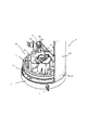
特に加熱液体および/または冷たいあるいは加熱された泡立ち液体を生成するためにミルクから成るあるいはミルクに基づく液体を調整するための本発明に係る器具1が図1および図1aに示されており、図2および図3は、図1の部分Aおよび部分Bのそれぞれの拡大図を示している。
An
器具1は、調整されるべき液体を受けるためのタンク10と、タンク10の下側に位置する閉塞された区画室20と、タンク10内に収容される液体に対して調整効果を与えるための電気デバイス50とを有する。電気デバイス50は区画室20内に位置する。本発明によれば、区画室20は、水を通さないようにされており、電気デバイス50を収容する区画室20内に流水を浸入させることなく流水で洗浄できる。
The
図1に示されるように、区画室20は、硬質プラスチック底部30に組み付けられる略管状スタンド21によって形成される。区画室20の上部は、スタンド21の内側に位置してスタンド21に固定されるタンク10によって画定される。したがって、管状スタンド21、底部30、および、タンク10は、組み立てられる際に一緒にチャンバ20を形成する3つのケーシング部品である。
As shown in FIG. 1, the
タンク10およびスタンド21は、金属から形成されて、その上端で互いに溶接されており、それにより、2つの部品のアセンブリが本発明にしたがって水を通さないようにされる。底部30は、硬質プラスチック材料などの硬質材料から形成される。タンク10は、一般にプラスチックから形成され且つ外周シールリング12を有する取り外し可能な蓋11で覆われる。
The
図1の部分Bの拡大図を示す図3に描かれるように、底部30は、管状スタンド21の内側下端と対向する直立周壁31を有する。壁31は、スタンド21と対向し且つ底部30の全周にわたって延びる外周溝32を有する。溝32内に位置する外周シールリング33(例えば、Oリングタイプのガスケット)が壁31の全周にわたって延びる。シールリング33は、NBRなどの弾性変形可能な材料から形成される。リング33は、リング33を溝32内へと押し付ける、特にスタンド21の下端と略平行に対向する溝の表面34に対してリング33を押し付けるスタンド21の内側下端によって溝32内で締め付けられて圧縮される。したがって、圧縮されたシールリング33がスタンド21と底部30との間の任意の隙間または通路を密封し、それにより、手によるあるいは更には食器洗い機内での洗浄中にスタンド21と底部30との間で水の浸入が起こり得ない。
As illustrated in FIG. 3, which shows an enlarged view of the portion B of FIG. 1, the bottom 30 has an upright
また、図1および図3に示されるように、スタンド21内への底部30の導入を容易にするため、管状スタンド21の下端22が外側に僅かに曲げられるとともに、直立底壁31の上端が面取り部35を有する。
Further, as shown in FIGS. 1 and 3, in order to facilitate the introduction of the bottom 30 into the
また、図1aに示されるように、ユーザによるチャンバ21の望ましくない開放を避けるため、底部30がスタンド21内に取り外し不能にクリップ留めされてもよい。この目的のため、底部30は、底部30の外周部にわたって離間して配置される複数のクリップ90を含む。各クリップ90は、上側フック93を有する一対の略直立するフィンガ91、92と中心ロッド形状当接部材94とを有しており、フィンガ91、92および中心ロッド形状当接部材94は、スタンド21の内側に対して例えば溶接によって機械的に固定される支持部材96を有する対応するハンガ95とクリッピング係合するように配置される。
Also, as shown in FIG. 1a, the bottom 30 may be non-removably clipped into the
この説明から明らかなように、スタンド21内への底部30の組み付けは、特に底部30とスタンド21との間のシールリング33の主圧縮方向に対して略垂直な異なる方向で行なわれる。そのため、スタンド21内における底部30の組み付け機能とシール機能とが分離される。すなわち、シールは、スタンド21内での底部30の正確な位置決めとは無関係に且つハンガ95に対するクリップ90のクリッピングとは無関係に有効となるように、リング33がスタンド21内へ入れられるときに既に達成される。
As is apparent from this description, the assembly of the bottom 30 into the
更に、器具1は、コードレスタイプのものであり、図1aに示されるように電気ケーブル3を介してコンセント電源に接続されてもよい電気ベースユニット2によって取り外し可能に配置されて給電されるようになっている。したがって、底部30は、そのうちの1つが図1に示される複数のコードレスコネクタピン51を含んでおり、これらのコードレスコネクタピン51は、電気デバイス50に接続されるとともに、電気的に導電性が高い材料、一般的には銅またはアルミニウムまたはそれに基づく合金などの金属から形成される。コネクタピン51は、電気デバイス50を外部ベースユニット2に接続するために底部30の貫通開口または通路36を通じてチャンバ20の内側から外側へと延びている。
Furthermore, the
コネクタピン51に沿うチャンバ20内への水の浸入を避けるため、貫通開口または通路36は水を通さないようになっている。貫通開口または通路36は、チャンバ20内に通じる上開口37と、チャンバ20の外側に通じる下開口37’と、底部30の直立壁39間でシール要素38を収容する中間キャビティとを含む。シール部材38は、コネクタピン51の周囲で直立壁39とピン51との間の中間キャビティ内へと直接に流し込まれるシリコーンなどの弾性材料から形成されており、そのため、ピン51およびキャビティの表面、特に壁39の表面に強固に付着し、したがって、貫通開口または通路36の中間キャビティが水を通さなくなるようにする。また、貫通開口または通路36内でのピン51の移動を回避するために、ピン51は下開口37’に隣接する当接部52を備える。更に、ピン51は、コードレス器具1を支持してこれに電力を供給するベースユニット2上に器具1を装着するための溝を壁39およびピン51と協働して画定する垂直壁39’と関連付けられる。そのようなコードレスコネクタの詳細は、例えばWO2006/050900およびこの中で挙げられる引用文献に開示されている。
To avoid water ingress into the
また、器具1は、器具1の外側から電気デバイス50を制御するための複数のプッシュボタン60を備え、そのうちの1つが図1に示されるとともに、図1の部分Aの拡大図を示す図2に示されている。
The
プッシュボタン60は、スタンド21の貫通開口を通じてチャンバ20内へ延びる。ボタン60は、金属、セラミック、硬質プラスチック、および/または、他の硬質材料から形成される硬質リング67上に装着されあるいは注入されあるいは成型される弾性材料から形成されるコア61を有する。
The
コア61は、ユーザが押すことができるボタンヘッド62と、該ボタンヘッドと一体の動作伝達ロッド63とを備える。ボタンヘッド62は、外周シール要素64と一体であり、シール要素64およびボタンヘッド62と一体の弾性変形可能なヒンジ65を介して外周シール要素と接続される。
The
図2に示されるように、シール要素64は、硬質リング67とスタンド21の(硬質)部分23との間で圧縮変形される。部分23は、プッシュボタン60を収容する貫通開口を画定するとともに、硬質リング67の表面と略平行に対向する表面を有し、これらの2つの表面は、シール要素64を圧搾して、ボタン60のための貫通開口が水を通さないようにする。更に、貫通開口内へのボタン60の挿入を容易にするため、また、スタンド21内にボタン60を取り外し不能にクリップ留めして水不浸透性を悪化させるボタンの任意の移動または配置ミスを回避するために、シール要素64は横方向に延びる傾斜した矢印状の端部66を有する。
As shown in FIG. 2, the sealing
更に、ボタン60のロッド63は、チャンバ20内において接点要素55へ向けてガイド部材53間で延びており、接点要素55は、電気デバイス50と接続されるとともに、ボタンヘッド62および伝達ロッド63をそれらに抗して押圧することによりヒンジ65を変形させることで動作され得る。
Further, the
同じ参照符号が同じ要素を示す図2aは、本発明に係る他のボタン装置を示している。 FIG. 2a, in which the same reference numerals indicate the same elements, shows another button device according to the invention.
プッシュボタン60”は、硬質環状クリッピング装置67’を使用して、スタンド21の硬質壁部23によって画定される貫通開口内に固定される。クリッピング装置67’は、シールリング64に沿って延び且つシールリング64を壁23の外面23bに抗して付勢する環状首部67aを有する。環状首部67aは、そのうちの1つが図2aの下部に示される一連の離間するクリッピングフィンガによって形成され、クリッピングフィンガは、フック67bを有するアーム67aと、面取り部67dと、壁部23の縁部上にわたって延びる端部67eと、壁部23の出っ張り23a上にわたって延びる円形フランジ67cとを有する。フランジ67cは、ボタンの弾性ヒンジ65の外周延在部65aによって覆われる。シールリング64は、アーム67aの根元間で延びる接続部64aを介してボタンヘッド62に接続され、前記根元がアーム67aを円形フランジ67cに結合する。
The
各クリッピングフィンガは、僅かに弾力があり、壁部23によって画定される貫通開口内への環状クリッピング装置67’の出っ張り23までの挿入を可能にするためおよび壁部23の縁部を越えてフック67bをクリップ留めするために面取り部27dを有する。
Each clipping finger is slightly resilient and hooks into the through opening defined by the
更に、ボタンヘッド62が動作伝達ハードロッド63’に組み付けられ、動作伝達ハードロッド63’の端部63”は、ボタンヘッド62がユーザによって押圧されるときに接点要素55を押圧するようになっている。
Further, the
同じ参照符号が同じ要素を示す図4は、比較の従来技術のボタン60’の配置を示している。同様のボタンが前述したWO2006/050900に開示されている。 FIG. 4, where the same reference numbers indicate the same elements, shows the arrangement of a comparative prior art button 60 '. Similar buttons are disclosed in the aforementioned WO 2006/050900.
ボタン60’は、スタンド21を貫通して延びる貫通開口内に、ボタン60’の外周一体部64’によって固定され、外周一体部64’は、スタンド21の縁部23’、すなわち、ボタン60’のための貫通開口を画定する縁部23’にクリップ留めされる。図4において容易に分かるように、外周一体部64’は、縁23’に抗して付勢されて押圧されない。この一体部64’は、ボタン60’に沿うチャンバ20内への通路をしっかりと塞がず、したがって、特にボタン60’が押圧されて縁部23’周りで外周部64’の屈曲および変位が引き起こされる際に水を通さないシールを行なうことができない。これは、チャンバ20に浸透して器具の電気部分の耐久性を損なう場合があるミルク流出にボタンが晒される場合に、いっそう問題となる。
The
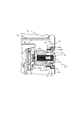
同じ参照符号が同じ要素を示す図5は、本発明に係る他の器具1を示している。器具1は、タンク10上に蓋を伴うことなく示されている。従来技術の器具とは対照的に、器具の外部部品に対するミルクの跳ね飛びがもはや問題にならず、そのため、蓋が無くても器具を動作させることができ、それにより、調整処理中にユーザが液体に接近できる。
FIG. 5, in which the same reference numerals indicate the same elements, shows another
略管状のスタンド21’は、タンク10の材料、一般的には金属系材料に対して溶接することができない材料、一般的にはプラスチック材料から形成される。それにもかかわらず、スタンド21’と該スタンド内に位置するタンク10とから成るアセンブリの水不浸透性を確保するため、タンク10とスタンド21’との間の接合部全体に沿って、すなわち、タンク10の全周にわたって外周シール要素15が使用される。シール要素15は、NBRなどの弾性材料から形成されており、タンク10とスタンド21’との間で永久的に圧縮される。
The generally tubular stand 21 'is formed from a material that is not weldable to the material of the
図6に更に詳しく示されるように、シール要素15は、タンク10の表面の一部分上にわたって延び且つ該一部分に当接して配置される本体16と、本体16からスタンド21’の上端の内面へと突出する3つの外周横方向部材17とを有する。外周横方向部材17は、本体16に沿ってタンク10の全周にわたって延びている。スタンド21’の内面は、タンク10の前記表面と略平行に対向している。これらの2つの表面は、これらの表面間に位置するシール要素15の横方向部材17および本体16を圧縮する。
As shown in more detail in FIG. 6, the sealing
因みに、スタンド21の貫通開口内でプッシュボタン60を固定するシール要素64は、スタンド21の部分23に抗して圧縮される同様の外周横方向部材を有する。
Incidentally, the sealing
また、タンク10の上端は、タンク10に沿って延びる下向外周硬質支持部材10’と関連付けられ、下向外周硬質支持部材10’はタンクから離間するように屈曲される下部10”を有する。硬質支持部材10’,10”は、スタンド21’を位置決めして該スタンド上にタンク10を固定するのに役立つ。支持部材10’,10”は、スタンド21’をシール部材15およびタンク10に抗して付勢すると同時に、スタンド21’の肩部23上に当て付いて、タンク10をスタンド21’に固定する。シール要素15は、その上端に、タンク10と該タンクから離間するように屈曲する下部10”との間の隙間をシールする柔軟横方向部材18を更に備える。
The upper end of the
器具1は、超音波溶接によってスタンド21’に接続される底部30’を有する。スタンド21’および底部30’は、少なくともそれらが互いに溶接される場所が、溶接の目的に適合する熱可塑性材料から成る。
The
図5の部分Dの拡大図である図7に更に詳しく示されるように、底部30’は2つの平行な直立外周壁301、302を有しており、直立外周壁301、302はそれらの間に外周溝303を画定する。これらの壁301、302および溝303は底部30’の全周に沿って延びている。スタンド21’の下部は、大きく屈曲される、特に直角に曲げられる接続部材25を有しており、接続部材25は、スタンド21’の下部の内面から突出して、スタンド21’の内面全体に沿って延びることにより、底部30’の外周部上にわたって内側ループを形成するとともに、溝303内に収容するように形成される端部26を有する。しかしながら、端部26の幅は、組み付け前においては、溝303の幅よりも大きいため、接続部材25および底部30’は、端部26の表面の表面溶融を引き起こす超音波溶接機を用いて組み付けられ、また、端部26の表面は、溶接プロセス中、それに対応して溶融する外周壁301、302の表面と接触する。そのような溶接は、スタンド21’と底部30’との間で完全に水を通さない結合を行なう。
As shown in more detail in FIG. 7, which is an enlarged view of portion D of FIG. 5, the bottom 30 'has two parallel upstanding outer
1つ以上のネジ70を使用して機器1内に底部30’を更に固定することができる。図5の部分Dの拡大図である図7に示されるように、ネジ70は底部30’の貫通開口を貫通して延びている。この貫通開口は、ネジ70の周囲に嵌め付けられ且つネジ70と貫通開口を画定する対向壁との間で圧縮されるシールリング(例えば、Oリングタイプのガスケット)71によって水を通さないようにされる。また、タンク10の下部は、そのうちの1つが図5および図8に示される脚部13に対して溶接されあるいは接続されており、脚部13は、スタンド21’に沿って底部30’へ向けて下方へ延びるとともに、ネジ70を固定するためのネジ穴14を備えている。
One or
更に、図1および図5に示されるタンク10には攪拌器85、85’のための攪拌器位置決め要素80が設けられ、攪拌器位置決め要素80上に攪拌器85、85’が取り外し可能に装着される。
Further, the
攪拌器85、85’は、トロイダル形状のワイヤの巻回、インペラ、ブレード、格子、または、ニードルなどの攪拌要素86を有する外周部を含む。回転攪拌器の適切な駆動手段および構造、特にチャンバ内の電気デバイスとタンク内の攪拌器との間の磁気伝達装置は、前述したWO2006/050900に更に詳しく開示されている。
The
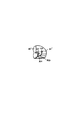
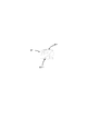
しかしながら、従来技術の攪拌器とは対照的に、攪拌器85、85’は、外周部86から略直立して延びる上端部87、88、89を有する。この上端部は、人の指に適応してタンク10の位置決め要素80に対する攪拌器85,85’の抜き取りおよび挿入を容易にするようになっている保持部87、88、89を有する。
However, in contrast to the prior art stirrer, the
上端部87、88、89は、略半円の弓形部材87を含む。図1に示される攪拌器85とは異なり、図5に描かれる攪拌器85’は、弓形部材87の上端から上方へ延びる細長い直立ロッド88を更に備える。また、人の指による把持を容易にするため、直立ロッド88の上端には横方向に突出する略球状要素89が設けられる。
The
同じ参照符号が同じ要素を示す図9および図10は攪拌器85を更に詳しく示している。攪拌要素86は、第2の接続部材87cを介して支持部材87aに固定されるリング86’上に配置されるループ状のスプリング要素の形態を成している。弓形部材87は、第1の接続部材87bを介して支持部材87aに固定される。更に、支持部材87aは、攪拌器位置決め要素80の通過のための貫通開口Dを有する。
9 and 10 where the same reference numbers indicate the same elements show the
図10に断面で示される弓形部材87および接続部材87bは、凸状外面87’を有するとともに、随意的に、凹状のあるいは直線状の内面87”を有する。任意の理論に縛られることなく、そのような断面は、ミルクなどの液体中での攪拌器85の回転中に、特に回転中に最大の接線速度に晒される接続部材87bの近傍で、キャビテーションの発生を促進し、それにより、細かい気泡が発生し、液体の泡立ちが改善されると考えられる。
The
同じ参照符号が同じ要素を示す図11は、本発明の攪拌器85”の他の実施形態を示している。特に、攪拌器85”は、図9のようなスプリング攪拌要素を有する代わりに、2つのブレード状要素86”を有する。
FIG. 11, in which the same reference numbers indicate the same elements, shows another embodiment of the
本発明の更なる変形(図示せず)において、攪拌器の弓形部材は、半円形状ではなく、略放物線、半楕円、または、テーパ形状等の形状を有することができる。 In a further variation (not shown) of the invention, the arcuate member of the agitator may have a shape such as a substantially parabola, a semi-ellipse, or a tapered shape, rather than a semi-circular shape.
図1および図5に示されるように、器具には、電気デバイス50に接続される加熱要素が取り付けられている。適した加熱要素の詳細は、前述したWO2006/050900に更に詳しく開示されている。
As shown in FIGS. 1 and 5, the appliance is fitted with a heating element that is connected to an
加熱要素56および攪拌器85、85’は、ユーザによりプッシュボタン60を介して制御されてもよい。攪拌器は、例えば攪拌器の幾つかの回転速度を選択できる可能性がユーザに与えられる場合には、1つ以上のボタンと関連付けられてもよい。同様に、所望の加熱温度を選択するために幾つかのボタンが設けられてもよい。当業者であれば分かるように、ユーザが例えば所望の加熱温度、攪拌速度、および、調整継続時間および調整プロファイルを選択できるようにするべく制御手段を選択して構成するために多くの変形が可能である。
The
Claims (15)
攪拌器位置決め要素(80)上に取り外し可能に装着されるようになっている位置決め底部と、
攪拌器要素(86)を有する外周部と、
を備え、
上端部(87,88,89)は、前記外周部(86)から略直立して延び、前記上端部は、保持部(87.88.89)を形成し、前記保持部は、人の指に適応して前記位置決め要素(80)に対する前記攪拌器の抜き取り及び挿入を容易にするようになっている、攪拌器。 A rotatable foaming stirrer (85, 85 '),
A positioning bottom adapted to be removably mounted on the agitator positioning element (80);
An outer periphery having a stirrer element (86);
With
The upper end portion (87, 88, 89) extends substantially upright from the outer peripheral portion (86), the upper end portion forms a holding portion (87.88.89), and the holding portion is a human finger. A stirrer adapted to facilitate the extraction and insertion of the stirrer with respect to the positioning element (80).
Applications Claiming Priority (10)
| Application Number | Priority Date | Filing Date | Title |
|---|---|---|---|
| DE202007007337.2 | 2007-05-23 | ||
| DE202007007338.0 | 2007-05-23 | ||
| DE202007007340.2 | 2007-05-23 | ||
| DE200720007339 DE202007007339U1 (en) | 2007-05-23 | 2007-05-23 | Button assembly and Milchaufschäumgerät with such a button assembly |
| DE202007007339.9 | 2007-05-23 | ||
| DE200720007337 DE202007007337U1 (en) | 2007-05-23 | 2007-05-23 | Stirring tool, in particular for a milk frother and milk frother |
| DE202007007340U DE202007007340U1 (en) | 2007-05-23 | 2007-05-23 | Lid, in particular for a milk frother and milk frother |
| DE200720007338 DE202007007338U1 (en) | 2007-05-23 | 2007-05-23 | Electric kitchen appliance |
| EP07124050.1 | 2007-12-24 | ||
| EP07124050 | 2007-12-24 |
Related Parent Applications (1)
| Application Number | Title | Priority Date | Filing Date |
|---|---|---|---|
| JP2010508861A Division JP2010527671A (en) | 2007-05-23 | 2008-05-23 | Apparatus for adjusting milk-based liquids |
Publications (2)
| Publication Number | Publication Date |
|---|---|
| JP2014111154A true JP2014111154A (en) | 2014-06-19 |
| JP5881754B2 JP5881754B2 (en) | 2016-03-09 |
Family
ID=39830231
Family Applications (2)
| Application Number | Title | Priority Date | Filing Date |
|---|---|---|---|
| JP2010508861A Pending JP2010527671A (en) | 2007-05-23 | 2008-05-23 | Apparatus for adjusting milk-based liquids |
| JP2014012376A Active JP5881754B2 (en) | 2007-05-23 | 2014-01-27 | Rotating foaming stirrer and foaming tank |
Family Applications Before (1)
| Application Number | Title | Priority Date | Filing Date |
|---|---|---|---|
| JP2010508861A Pending JP2010527671A (en) | 2007-05-23 | 2008-05-23 | Apparatus for adjusting milk-based liquids |
Country Status (15)
| Country | Link |
|---|---|
| US (1) | US8668376B2 (en) |
| EP (3) | EP2152127B1 (en) |
| JP (2) | JP2010527671A (en) |
| KR (1) | KR20100017155A (en) |
| CN (2) | CN102846222B (en) |
| AU (1) | AU2008252932B2 (en) |
| BR (1) | BRPI0812160A2 (en) |
| CA (1) | CA2686464C (en) |
| ES (2) | ES2561359T3 (en) |
| IL (1) | IL201718A0 (en) |
| MX (1) | MX2009012664A (en) |
| PT (2) | PT2174576E (en) |
| RU (1) | RU2476137C2 (en) |
| WO (1) | WO2008142154A1 (en) |
| ZA (1) | ZA200909058B (en) |
Families Citing this family (57)
| Publication number | Priority date | Publication date | Assignee | Title |
|---|---|---|---|---|
| EP2341806B1 (en) | 2008-09-01 | 2013-01-02 | Nestec S.A. | Appliance for conditioning a milk-based liquid |
| DK2341805T3 (en) | 2008-09-01 | 2012-07-23 | Nestec Sa | DEVICE FOR FIND STEAM FOAM FOR A MILK BASED LIQUID |
| EP2229853A1 (en) | 2009-03-19 | 2010-09-22 | Green Lane Products Ltd. | Milk frothing device |
| CN102548457A (en) | 2009-09-29 | 2012-07-04 | 雀巢产品技术援助有限公司 | Arrangement for mixing a flavouring ingredient with a liquid carrier |
| WO2011082255A1 (en) * | 2009-12-31 | 2011-07-07 | Abbott Laboratories | Mixing system for mixing a powdered beverage with a liquid |
| JP2013517025A (en) | 2010-01-15 | 2013-05-16 | ネステク ソシエテ アノニム | Ergonomic service unit for beverage preparation machines |
| US20130025465A1 (en) | 2010-01-15 | 2013-01-31 | Nestec S.A. | Ergonomic ingredient holder and service unit coordination |
| NL2004113C2 (en) * | 2010-01-19 | 2011-07-20 | Foremost Bv | Device for agitating liquid foodstuff. |
| GB201004135D0 (en) * | 2010-03-12 | 2010-04-28 | Green Lane Products Ltd | Electrical apparatus |
| RU2560312C2 (en) | 2010-05-21 | 2015-08-20 | Нестек С.А. | Device for food product processing with remote control |
| JP4792118B1 (en) * | 2010-06-01 | 2011-10-12 | シャープ株式会社 | rice cooker |
| IT1400491B1 (en) * | 2010-06-03 | 2013-06-11 | De Longhi Appliances Srl | APPLIANCES FOR THE TREATMENT OF A FOOD LIQUID |
| AU2011264420B2 (en) * | 2010-06-11 | 2015-05-28 | Breville Pty Limited | Milk frother |
| GB201014663D0 (en) * | 2010-09-03 | 2010-10-20 | Gort Barten Alex | Milk frother |
| RU2571197C2 (en) | 2010-10-27 | 2015-12-20 | Нестек С.А. | Device for preparing beverages for different 3d environments |
| WO2012076848A1 (en) * | 2010-12-07 | 2012-06-14 | Alex Gort-Barten | Milk frother |
| EP2478804A1 (en) | 2011-01-21 | 2012-07-25 | Nestec S.A. | Milk frothing with pressurized gas |
| EP2802245B1 (en) | 2012-01-13 | 2016-12-14 | Nestec S.A. | Beverage machine with a removable module |
| EP2897504B1 (en) * | 2012-09-21 | 2016-02-24 | Koninklijke Philips N.V. | Beverage producing machine with a connector for a removable ingredient container |
| EP2931096A1 (en) * | 2012-12-12 | 2015-10-21 | Ides Development Company Limited | Frother, mixer |
| EP2965670B1 (en) | 2013-03-07 | 2019-09-11 | UCC Ueshima Coffee Co., Ltd. | Milk foamer |
| ITRM20130619A1 (en) * | 2013-11-11 | 2015-05-12 | Ides Dev Company Ltd N Ota In Commerc | DEVICE FOR THE PREPARATION OF A EMULSIFIED HOT DRINK |
| CN104841299B (en) * | 2015-04-16 | 2017-03-01 | 苏州大学 | The manufacture method of soft elastic container and the material mixed method based on this device in material mixed method and device and this device |
| WO2016202814A1 (en) | 2015-06-16 | 2016-12-22 | Nestec S.A. | Machine for homogenising a food substance |
| EP3310225B1 (en) | 2015-06-16 | 2020-07-29 | Société des Produits Nestlé S.A. | Food processor with low friction impeller support |
| WO2016202815A1 (en) | 2015-06-16 | 2016-12-22 | Nestec S.A. | Removal assistance food processor impeller |
| US10258191B2 (en) * | 2015-09-18 | 2019-04-16 | Starbucks Corporation | Beverage dispensing systems and methods |
| US10531761B2 (en) | 2015-09-18 | 2020-01-14 | Starbucks Corporation | Beverage preparation systems and methods |
| US11207437B2 (en) * | 2016-02-15 | 2021-12-28 | S. C. Johnson & Son, Inc. | Sealed heater engine for a wax warmer |
| US11517150B2 (en) | 2016-06-13 | 2022-12-06 | Societe Des Produits Nestle S.A. | Multipurpose beverage preparation machine and electronic device for controlling the same |
| IT201600122005A1 (en) * | 2016-12-01 | 2018-06-01 | Lavazza Luigi Spa | Apparatus for preparing a foam from a liquid, in particular a food liquid, such as milk or a milk-based liquid. |
| US11206941B2 (en) | 2016-12-13 | 2021-12-28 | Societe Des Produits Nestle S.A. | High torque magnetic transmission for whisk |
| RU2757847C2 (en) | 2016-12-13 | 2021-10-21 | Сосьете Де Продюи Нестле С.А. | Controlling the heating mode of food processor |
| CA3042138A1 (en) | 2016-12-13 | 2018-06-21 | Nestec S.A. | Ergonomic whisk for food processing |
| US11083328B2 (en) | 2017-06-22 | 2021-08-10 | Starbucks Corporation | Apparatus and method for foaming a beverage |
| US20200359841A1 (en) | 2017-11-23 | 2020-11-19 | Societe Des Produits Nestle S.A. | Controlled heat management for food processor |
| EP3713461A1 (en) | 2017-11-23 | 2020-09-30 | Société des Produits Nestlé S.A. | Adjusted thermal generation for food processing |
| US20210007554A1 (en) | 2018-03-29 | 2021-01-14 | Societe Des Produits Nestle S.A. | Controlled positioning in food processor |
| US11930964B2 (en) | 2018-03-29 | 2024-03-19 | Societe Des Produits Nestle S.A. | Heat management for food processor |
| EP3773096A1 (en) | 2018-03-29 | 2021-02-17 | Société des Produits Nestlé S.A. | Handling of food processor |
| JP7011520B2 (en) * | 2018-04-16 | 2022-01-26 | 象印マホービン株式会社 | Cooking device |
| WO2019211213A1 (en) | 2018-04-30 | 2019-11-07 | Societe Des Produits Nestle S.A. | Handling of beverage |
| TWI671047B (en) * | 2018-06-05 | 2019-09-11 | 黃俊凱 | Intelligent liquid control system and control method thereof |
| CN114051384A (en) | 2019-07-11 | 2022-02-15 | 雀巢产品有限公司 | Hand-held large-scale processing tank |
| CA3145227A1 (en) | 2019-07-11 | 2021-01-14 | Societe Des Produits Nestle S.A. | Regulation of wisking of a food substance |
| AU2021395337A1 (en) | 2020-12-07 | 2023-05-25 | Société des Produits Nestlé SA | Machine for heating and agitating a liquid food substance with shutdown device |
| US20230055906A1 (en) * | 2021-08-20 | 2023-02-23 | Paula J. CRASHLEY | Mixing accessory |
| US11812892B1 (en) | 2022-04-25 | 2023-11-14 | Sharkninja Operating Llc | Fluid texturing device |
| US11647860B1 (en) | 2022-05-13 | 2023-05-16 | Sharkninja Operating Llc | Flavored beverage carbonation system |
| WO2023216231A1 (en) | 2022-05-13 | 2023-11-16 | Sharkninja Operating Llc | Agitator for a carbonation system |
| US11751585B1 (en) | 2022-05-13 | 2023-09-12 | Sharkninja Operating Llc | Flavored beverage carbonation system |
| US11634314B1 (en) | 2022-11-17 | 2023-04-25 | Sharkninja Operating Llc | Dosing accuracy |
| US11745996B1 (en) | 2022-11-17 | 2023-09-05 | Sharkninja Operating Llc | Ingredient containers for use with beverage dispensers |
| US11738988B1 (en) | 2022-11-17 | 2023-08-29 | Sharkninja Operating Llc | Ingredient container valve control |
| US11871867B1 (en) | 2023-03-22 | 2024-01-16 | Sharkninja Operating Llc | Additive container with bottom cover |
| US11925287B1 (en) | 2023-03-22 | 2024-03-12 | Sharkninja Operating Llc | Additive container with inlet tube |
| US11931704B1 (en) | 2023-06-16 | 2024-03-19 | Sharkninja Operating Llc | Carbonation chamber |
Citations (7)
| Publication number | Priority date | Publication date | Assignee | Title |
|---|---|---|---|---|
| JPS5247589U (en) * | 1975-09-30 | 1977-04-04 | ||
| US4027582A (en) * | 1976-01-19 | 1977-06-07 | Connell Gerard Peter O | Art of brewing individual servings of coffee in a cup |
| JPS5379887U (en) * | 1976-12-03 | 1978-07-03 | ||
| JPH0436948U (en) * | 1990-07-19 | 1992-03-27 | ||
| JPH11197521A (en) * | 1998-01-14 | 1999-07-27 | Yamamoto Denko Kk | Desk rice milling device |
| US20010002891A1 (en) * | 1999-07-13 | 2001-06-07 | Stephen W. Frankel | Method and apparatus to automatically heat and froth milk for beverages |
| EP1656866A1 (en) * | 2004-11-12 | 2006-05-17 | Nestec S.A. | Device and method for the preparation of froth from a liquid milk-based food product |
Family Cites Families (60)
| Publication number | Priority date | Publication date | Assignee | Title |
|---|---|---|---|---|
| US1293964A (en) * | 1918-02-23 | 1919-02-11 | Perl Monroe Spink | Electric heater and cooker. |
| GB243082A (en) | 1924-08-25 | 1925-11-25 | Walter George Goodson | Improvements in or relating to chain elevators, conveyers or the like for storing ordisplaying goods |
| US1984975A (en) * | 1934-09-27 | 1934-12-18 | William B Lodder | Agitator |
| US2282866A (en) | 1939-11-27 | 1942-05-12 | Hagen Harold | Electric liquid mixer and heater |
| US2459224A (en) | 1946-08-17 | 1949-01-18 | William L Hendricks | Magnetically operated stirrer for mixing liquids |
| US2518758A (en) | 1949-06-22 | 1950-08-15 | George B Cook | Magnetic stirring apparatus |
| BE531130A (en) | 1953-08-18 | |||
| US2932493A (en) | 1957-09-09 | 1960-04-12 | Magic Whirl Dispensers Inc | Beverage mixer |
| DE1131372B (en) | 1960-05-19 | 1962-06-14 | Siemens Elektrogeraete Gmbh | Kitchen machine |
| US3168294A (en) | 1960-08-15 | 1965-02-02 | Hasumura Tadashi | Mixing apparatus wherein magnets are utilized |
| US3172645A (en) | 1961-07-21 | 1965-03-09 | Doryce Appleton | Agitator for foods of a liquid form containing solids |
| US3421528A (en) | 1964-10-21 | 1969-01-14 | Ludgero S A Gomez | Denture cleaning device |
| US3351539A (en) * | 1965-04-06 | 1967-11-07 | Branson Instr | Sonic agitating method and apparatus |
| US3356349A (en) | 1966-04-14 | 1967-12-05 | Westinghouse Electric Corp | Range stirring apparatus |
| DE1554670A1 (en) | 1966-04-15 | 1970-02-19 | Waggon Und Maschinenfabriken G | Mixing device for beverage machines |
| US3454745A (en) * | 1967-09-25 | 1969-07-08 | Knapp Monarch | Heater for shaving lather containers |
| US4162855A (en) | 1974-11-18 | 1979-07-31 | Spectroderm International, Inc. | Magnetic stirrer apparatus |
| JPS5922917B2 (en) * | 1977-04-06 | 1984-05-29 | シチズン時計株式会社 | Fixed structure of watch glass |
| US4209259A (en) | 1978-11-01 | 1980-06-24 | Rains Robert L | Magnetic mixer |
| US4537332A (en) | 1982-09-30 | 1985-08-27 | Jet Spray Corp. | Beverage dispenser with improved in-bowl whipper |
| US4480926A (en) | 1983-05-13 | 1984-11-06 | Lattery Jr William F | Powdered food product mixing device |
| JPS60151452A (en) | 1984-01-15 | 1985-08-09 | Ckd Corp | Linearly reciprocating driving device |
| JPS60194914A (en) | 1984-03-16 | 1985-10-03 | 松下電器産業株式会社 | Mixer |
| CA1242661A (en) | 1984-08-29 | 1988-10-04 | Shigeki Mukouyama | Method of producing fruit wine, etc. |
| JPS63177821A (en) | 1987-01-19 | 1988-07-22 | 株式会社日立ホームテック | Cooking machine |
| JPH0241893Y2 (en) * | 1987-07-02 | 1990-11-08 | ||
| US5136713A (en) | 1989-08-25 | 1992-08-04 | International Business Machines Corporation | Apparatus and method for decreasing the memory requirements for bios in a personal computer system |
| FR2655531A1 (en) | 1989-12-13 | 1991-06-14 | Moulinex Sa | APPARATUS FOR PUNCHING AND COOKING. |
| CN2057839U (en) * | 1989-12-16 | 1990-06-06 | 陈玉峰 | Container with mixer structure |
| DE8915094U1 (en) | 1989-12-20 | 1990-02-08 | Spielvogel, Peter, 1000 Berlin, De | |
| JPH0741063Y2 (en) * | 1990-04-10 | 1995-09-20 | オムロン株式会社 | Electronic device operation part structure |
| JPH08222448A (en) * | 1995-02-13 | 1996-08-30 | Matsushita Electric Ind Co Ltd | Mold transformer |
| DE29602684U1 (en) | 1996-02-15 | 1996-06-05 | Rubino Gennaro | Stirrer |
| DE19624648A1 (en) | 1996-06-20 | 1998-01-02 | Bosch Siemens Hausgeraete | Special cooking pot for cooking plate-simmering unit |
| JPH1037940A (en) * | 1996-07-26 | 1998-02-13 | Nec Shizuoka Ltd | Waterproof structure and waterproof case for screw fixing part |
| SE511230C2 (en) | 1998-01-19 | 1999-08-30 | Novaseptic Equipment Ab | Apparatus for treating materials in a container, especially for dispersing or homogenizing liquids or suspending solids in liquids |
| US6318247B1 (en) | 1998-04-02 | 2001-11-20 | Sunbeam Products, Inc. | Appliance for preparation of heated and stirred beverages and foods |
| US6793167B2 (en) | 1999-01-12 | 2004-09-21 | Island Oasis Cocktail Company, Inc. | Food processing apparatus including magnetic drive |
| US6231268B1 (en) * | 1999-04-19 | 2001-05-15 | Limnetics Corporation | Apparatus and method for treatment of large water bodies by directed circulation |
| FR2795875B1 (en) | 1999-07-01 | 2001-12-14 | Parsons Internat | IMPROVED SAFETY SYSTEM OF ELECTRIC HEATER |
| US20010036124A1 (en) * | 2000-04-07 | 2001-11-01 | Scott Rubenstein | Beverage container with integrated stirring device |
| DE10019126A1 (en) | 2000-04-18 | 2001-10-25 | Vorwerk Co Interholding | Kitchen machine with stirring vessel and drive for stirrer mechanism in stirring vessel so that vessel is heatable-up in its lower region and possesses base sided dome having stirring mechanism holder |
| JP4345212B2 (en) * | 2000-09-14 | 2009-10-14 | パナソニック電工株式会社 | Rubber switch waterproof structure |
| US7270156B2 (en) * | 2000-11-13 | 2007-09-18 | Back To Basics Products, Llc | Beverage mixer and heater |
| GB2369037A (en) | 2000-11-16 | 2002-05-22 | Strix Ltd | Appliances for heating liquids and foodstuffs |
| US6289793B1 (en) | 2001-03-01 | 2001-09-18 | Tsann Kuen Usa, Inc. | Cooking appliance |
| CA2443102A1 (en) * | 2001-04-06 | 2002-10-17 | Scott Nicol | Carbonation system and method |
| WO2002096761A2 (en) | 2001-05-22 | 2002-12-05 | Shurflo Pump Manufacturing Company, Inc. | Appliance and an appliance drive unit |
| WO2003003888A1 (en) | 2001-07-03 | 2003-01-16 | Adalberto Legorreta Gutierrez | Container with internal mixing means |
| US6948223B2 (en) | 2002-05-03 | 2005-09-27 | Medtronic Vascular, Inc. | Apparatus for mounting a stent onto a stent delivery system |
| GB0311959D0 (en) * | 2003-05-23 | 2003-06-25 | Glaxo Group Ltd | Energy delivery system |
| CN2652296Y (en) * | 2003-08-08 | 2004-11-03 | 陈栋 | Milk foaming machine |
| JP3651685B2 (en) * | 2003-10-01 | 2005-05-25 | 弘培 金 | Home cooked rice porridge and method for cooking porridge using the same |
| JP2005207328A (en) * | 2004-01-23 | 2005-08-04 | Toyota Industries Corp | Compressor |
| US20050207272A1 (en) * | 2004-03-18 | 2005-09-22 | National-Oilwell, L.P. | Mud tank with pressurized compartment |
| US20060018187A1 (en) * | 2004-05-07 | 2006-01-26 | Roberto Donna | Mixing device for use with insulated container |
| JP4352178B2 (en) * | 2005-06-09 | 2009-10-28 | 株式会社カシオ日立モバイルコミュニケーションズ | Pushbutton switch waterproof structure and electronic device |
| JP4487892B2 (en) * | 2005-09-22 | 2010-06-23 | パナソニック電工株式会社 | Waterproof structure of switch device |
| GB2434082A (en) * | 2006-01-12 | 2007-07-18 | Stefano Cuffaro | Food cooking and stirring device |
| DE102007008134A1 (en) * | 2007-02-19 | 2008-08-21 | Invent Umwelt- Und Verfahrenstechnik Ag | Horizontal agitator and method for generating a flow in a clarifier with the horizontal agitator |
-
2008
- 2008-05-23 MX MX2009012664A patent/MX2009012664A/en active IP Right Grant
- 2008-05-23 PT PT90133968T patent/PT2174576E/en unknown
- 2008-05-23 KR KR1020097024155A patent/KR20100017155A/en not_active Application Discontinuation
- 2008-05-23 US US12/601,186 patent/US8668376B2/en active Active
- 2008-05-23 JP JP2010508861A patent/JP2010527671A/en active Pending
- 2008-05-23 CN CN201210342119.8A patent/CN102846222B/en active Active
- 2008-05-23 BR BRPI0812160-5A2A patent/BRPI0812160A2/en not_active Application Discontinuation
- 2008-05-23 ES ES08759950.2T patent/ES2561359T3/en active Active
- 2008-05-23 CN CN200880017065XA patent/CN101686766B/en active Active
- 2008-05-23 ES ES09013396T patent/ES2430888T3/en active Active
- 2008-05-23 EP EP08759950.2A patent/EP2152127B1/en active Active
- 2008-05-23 PT PT87599502T patent/PT2152127E/en unknown
- 2008-05-23 WO PCT/EP2008/056349 patent/WO2008142154A1/en active Application Filing
- 2008-05-23 EP EP09013396.8A patent/EP2174576B1/en active Active
- 2008-05-23 CA CA2686464A patent/CA2686464C/en active Active
- 2008-05-23 EP EP20090013395 patent/EP2174575A1/en not_active Withdrawn
- 2008-05-23 RU RU2009147756/12A patent/RU2476137C2/en active
- 2008-05-23 AU AU2008252932A patent/AU2008252932B2/en active Active
-
2009
- 2009-10-22 IL IL201718A patent/IL201718A0/en unknown
- 2009-12-18 ZA ZA2009/09058A patent/ZA200909058B/en unknown
-
2014
- 2014-01-27 JP JP2014012376A patent/JP5881754B2/en active Active
Patent Citations (7)
| Publication number | Priority date | Publication date | Assignee | Title |
|---|---|---|---|---|
| JPS5247589U (en) * | 1975-09-30 | 1977-04-04 | ||
| US4027582A (en) * | 1976-01-19 | 1977-06-07 | Connell Gerard Peter O | Art of brewing individual servings of coffee in a cup |
| JPS5379887U (en) * | 1976-12-03 | 1978-07-03 | ||
| JPH0436948U (en) * | 1990-07-19 | 1992-03-27 | ||
| JPH11197521A (en) * | 1998-01-14 | 1999-07-27 | Yamamoto Denko Kk | Desk rice milling device |
| US20010002891A1 (en) * | 1999-07-13 | 2001-06-07 | Stephen W. Frankel | Method and apparatus to automatically heat and froth milk for beverages |
| EP1656866A1 (en) * | 2004-11-12 | 2006-05-17 | Nestec S.A. | Device and method for the preparation of froth from a liquid milk-based food product |
Also Published As
| Publication number | Publication date |
|---|---|
| RU2476137C2 (en) | 2013-02-27 |
| PT2174576E (en) | 2013-11-11 |
| EP2152127A1 (en) | 2010-02-17 |
| ES2430888T3 (en) | 2013-11-22 |
| EP2174576B1 (en) | 2013-08-07 |
| US20100192785A1 (en) | 2010-08-05 |
| EP2174575A1 (en) | 2010-04-14 |
| JP2010527671A (en) | 2010-08-19 |
| EP2174576A1 (en) | 2010-04-14 |
| CA2686464C (en) | 2015-06-30 |
| AU2008252932B2 (en) | 2014-07-24 |
| CN102846222B (en) | 2015-03-04 |
| AU2008252932A1 (en) | 2008-11-27 |
| CN102846222A (en) | 2013-01-02 |
| ES2561359T3 (en) | 2016-02-25 |
| KR20100017155A (en) | 2010-02-16 |
| JP5881754B2 (en) | 2016-03-09 |
| CA2686464A1 (en) | 2008-11-27 |
| EP2152127B1 (en) | 2015-12-23 |
| MX2009012664A (en) | 2010-02-18 |
| PT2152127E (en) | 2016-03-10 |
| CN101686766B (en) | 2013-04-24 |
| US8668376B2 (en) | 2014-03-11 |
| WO2008142154A1 (en) | 2008-11-27 |
| ZA200909058B (en) | 2011-05-25 |
| RU2009147756A (en) | 2011-06-27 |
| CN101686766A (en) | 2010-03-31 |
| IL201718A0 (en) | 2010-05-31 |
| BRPI0812160A2 (en) | 2014-12-16 |
Similar Documents
| Publication | Publication Date | Title |
|---|---|---|
| JP5881754B2 (en) | Rotating foaming stirrer and foaming tank | |
| JP5183208B2 (en) | Apparatus for making bubbles from food liquids | |
| JP5855092B2 (en) | Remotely controlled food processor | |
| RU2443382C2 (en) | Milk foaming machine | |
| CN110022737B (en) | Device for producing foam from a liquid | |
| JP2024042001A (en) | Handling food processors | |
| EP2882320B1 (en) | Milk frothing device | |
| CN102058327A (en) | Multifunctional combined appliance | |
| GB2504493A (en) | Milk frother with magnetic drive | |
| CN102366307A (en) | Liquid food heating and agitating foamer | |
| CN102551545A (en) | Heating milk foam machine | |
| KR101874157B1 (en) | food processing machine | |
| CN217659220U (en) | Detachable cooking machine | |
| CN215738363U (en) | Cooking apparatus | |
| CN217772117U (en) | Cooking pot with stirring stir-frying paddle | |
| KR20170073568A (en) | food processing machine | |
| CN114788640A (en) | Food preparation method, food processor and computer-readable storage medium |
Legal Events
| Date | Code | Title | Description |
|---|---|---|---|
| A131 | Notification of reasons for refusal |
Free format text: JAPANESE INTERMEDIATE CODE: A131 Effective date: 20141216 |
|
| A977 | Report on retrieval |
Free format text: JAPANESE INTERMEDIATE CODE: A971007 Effective date: 20141217 |
|
| A521 | Request for written amendment filed |
Free format text: JAPANESE INTERMEDIATE CODE: A523 Effective date: 20150316 |
|
| A131 | Notification of reasons for refusal |
Free format text: JAPANESE INTERMEDIATE CODE: A131 Effective date: 20150825 |
|
| A521 | Request for written amendment filed |
Free format text: JAPANESE INTERMEDIATE CODE: A523 Effective date: 20150902 |
|
| TRDD | Decision of grant or rejection written | ||
| A01 | Written decision to grant a patent or to grant a registration (utility model) |
Free format text: JAPANESE INTERMEDIATE CODE: A01 Effective date: 20160105 |
|
| A61 | First payment of annual fees (during grant procedure) |
Free format text: JAPANESE INTERMEDIATE CODE: A61 Effective date: 20160202 |
|
| R150 | Certificate of patent or registration of utility model |
Ref document number: 5881754 Country of ref document: JP Free format text: JAPANESE INTERMEDIATE CODE: R150 |
|
| R250 | Receipt of annual fees |
Free format text: JAPANESE INTERMEDIATE CODE: R250 |
|
| S111 | Request for change of ownership or part of ownership |
Free format text: JAPANESE INTERMEDIATE CODE: R313111 |
|
| R350 | Written notification of registration of transfer |
Free format text: JAPANESE INTERMEDIATE CODE: R350 |
|
| R250 | Receipt of annual fees |
Free format text: JAPANESE INTERMEDIATE CODE: R250 |
|
| R250 | Receipt of annual fees |
Free format text: JAPANESE INTERMEDIATE CODE: R250 |
|
| R250 | Receipt of annual fees |
Free format text: JAPANESE INTERMEDIATE CODE: R250 |
|
| R250 | Receipt of annual fees |
Free format text: JAPANESE INTERMEDIATE CODE: R250 |
|
| R250 | Receipt of annual fees |
Free format text: JAPANESE INTERMEDIATE CODE: R250 |