RU2539670C2 - Ergonomic connection of ingredient holder and service unit - Google Patents
Ergonomic connection of ingredient holder and service unit Download PDFInfo
- Publication number
- RU2539670C2 RU2539670C2 RU2012134787/12A RU2012134787A RU2539670C2 RU 2539670 C2 RU2539670 C2 RU 2539670C2 RU 2012134787/12 A RU2012134787/12 A RU 2012134787/12A RU 2012134787 A RU2012134787 A RU 2012134787A RU 2539670 C2 RU2539670 C2 RU 2539670C2
- Authority
- RU
- Russia
- Prior art keywords
- ingredient
- service unit
- holder
- location
- locking device
- Prior art date
Links
Images

Classifications
-
- A—HUMAN NECESSITIES
- A47—FURNITURE; DOMESTIC ARTICLES OR APPLIANCES; COFFEE MILLS; SPICE MILLS; SUCTION CLEANERS IN GENERAL
- A47J—KITCHEN EQUIPMENT; COFFEE MILLS; SPICE MILLS; APPARATUS FOR MAKING BEVERAGES
- A47J31/00—Apparatus for making beverages
- A47J31/44—Parts or details or accessories of beverage-making apparatus
Landscapes
- Engineering & Computer Science (AREA)
- Food Science & Technology (AREA)
- Apparatus For Making Beverages (AREA)
- Devices For Dispensing Beverages (AREA)
Abstract
Description
Область техники, к которой относится изобретениеFIELD OF THE INVENTION
Настоящее изобретение относится к заваривающим устройствам и сервисным блокам для машин приготовления напитков, а именно к машинам для приготовления напитков для приготовления напитков из предварительно разделенных на порции ингредиентов, подаваемых в капсуле в машину. Сервисный блок может включать устройство сбора использованного материала, образующегося во время операции машины приготовления напитков или подачи ингредиента, а именно жидкости, такой как вода.The present invention relates to brewing devices and service units for beverage machines, in particular, beverage machines for preparing beverages from pre-portioned ingredients supplied in a capsule to a machine. The service unit may include a device for collecting used material generated during the operation of a beverage preparation machine or supplying an ingredient, namely a liquid, such as water.
В целях настоящего описания "напиток" означает любую жидкую пищу, такую как чай, кофе, горячий или холодный шоколад, молоко, суп, детское питание и т.д. "Капсула" предназначена для вмещения любого предварительно разделенного на порции ингредиента напитка во вмещающей упаковке из любого материала, а именно в герметичной упаковке, например пластиковой, алюминиевой, пригодной для вторичного использования и/или биоразрушаемой упаковках, и любой формы и конструкции, включая мягкие поды и твердые картриджи, содержащие ингредиент.For the purposes of the present description, “beverage” means any liquid food such as tea, coffee, hot or cold chocolate, milk, soup, baby food, etc. The "capsule" is intended to contain any pre-portioned beverage ingredient in an enclosing package of any material, namely a sealed package, such as plastic, aluminum, recyclable and / or biodegradable packaging, and any shape and design, including soft pods and solid cartridges containing the ingredient.
Уровень техникиState of the art
Машины приготовления напитков становятся очень популярными и дома, и в офисах. Например, существуют машины для приготовления напитков, таких как кофе, чай, суп и другие подобные напитки, в которых, по меньшей мере, один ингредиент требуемого напитка, например молотого кофе, подается в капсуле в камеру извлечения машины.Beverage machines are becoming very popular both at home and in offices. For example, there are machines for preparing beverages, such as coffee, tea, soup, and other similar beverages, in which at least one ingredient of the desired beverage, such as ground coffee, is supplied in a capsule to the extraction chamber of the machine.
Ингредиент обычно извлекается жидкостью, такой как вода, циркулирующая в машине приготовления напитков из источника жидкости через камеру извлечения капсулы. Из камеры извлечения жидкость, содержащая извлеченный ингредиент, подается через вывод для напитка из машины потребителю, например в чашку или кружку потребителя, соответствующим образом размещенные под выводом в процессе приготовления напитка.The ingredient is usually recovered by a liquid, such as water circulating in a beverage machine from a liquid source through a capsule extraction chamber. From the extraction chamber, the liquid containing the recovered ingredient is supplied through the beverage outlet from the machine to the consumer, for example, into a consumer cup or mug appropriately placed under the outlet during the preparation of the beverage.
Применение капсул, таких как пластиковые и/или капсулы на основе алюминия для приготовления напитков, имеет множество преимуществ. Капсулы, а особенно капсулы на основе алюминия, герметичные и газонепроницаемые, и поэтому могут эффективно защищать ингредиент напитка в течение длительного периода времени от окружающей среды, такой как воздух, влажность или свет, до использования ингредиента. В результате такие капсулы предотвращают преждевременное ухудшение свойств ингредиента. Кроме того, капсулы ингредиента напитка удобны в обращении, гигиеничны, их использование позволяет меньше мыть машину для приготовления напитков, в частности, важные части камеры извлечения машины не вступают в контакт с ингредиентом напитка, содержащимся в капсуле, в процессе извлечения. Более того, в процессе использования, любой оставшийся ингредиент в основном остается внутри капсулы, в результате не нужно удалять оставшийся ингредиент из машины для приготовления напитков после использования.The use of capsules, such as plastic and / or aluminum-based capsules for the preparation of beverages, has many advantages. Capsules, and especially aluminum-based capsules, are sealed and gas-tight, and therefore can effectively protect the beverage ingredient for a long period of time from the environment, such as air, humidity or light, before using the ingredient. As a result, such capsules prevent premature deterioration of the ingredient. In addition, the capsules of the beverage ingredient are easy to handle, hygienic, their use allows you to wash the machine for making drinks less, in particular, important parts of the extraction chamber of the machine do not come into contact with the beverage ingredient contained in the capsule during the extraction process. Moreover, during use, any remaining ingredient remains mostly inside the capsule, as a result, it is not necessary to remove the remaining ingredient from the beverage machine after use.
Капсулы обычно вставляются отдельно в камеру извлечения машины, вручную или автоматически, из емкости для капсул. Затем горячая или холодная вода проходит через капсулу для приготовления или в другом случае извлечения ингредиента(ов), содержащегося в капсуле и приготовления требуемого напитка. Приготовленный напиток подается через вывод машины в чашку, кружку или другую приемную емкость потребителю.Capsules are usually inserted separately into the machine extraction chamber, manually or automatically, from the capsule container. Then, hot or cold water passes through the capsule to prepare or otherwise extract the ingredient (s) contained in the capsule and prepare the desired drink. The prepared drink is served through the output of the machine in a cup, mug or other receiving container to the consumer.
После извлечения использованные капсулы могут удаляться отдельно из машины для приготовления напитков после каждого цикла приготовления. Альтернативно использованные капсулы могут выводиться в приемник для использованных капсул и накапливаться в нем.Once removed, used capsules can be removed separately from the beverage machine after each preparation cycle. Alternatively, used capsules may be discharged to a capsule receiver and accumulated therein.
Машины для приготовления напитков преимущественно выпускаются с сервисным блоком для размещения использованных материалов, образующихся в процессе приготовления напитков. Использованные материалы включают оставшиеся ингредиенты, такие как молотый кофе после извлечения, и/или жидкость, такая как жидкость, выведенная из канала для жидкости между источником жидкости и выводом для напитка, или остатки напитка, разлитые на выводе напитка, например, в форме капель в конце процесса приготовления напитка. Например, сервисный блок включает устройство сбора отработанной жидкости, по меньшей мере, с одним из следующих устройств: опора для емкости потребителя с устройством извлечения жидкости, таким как сетка, устройство размещения отработанного ингредиента. Обычно опора для емкости потребителя и/или устройство размещения отработанного ингредиента располагаются над устройством сбора отработанной жидкости с тем, чтобы отработанная жидкость под действием сил гравитации сливалась из опоры для емкости потребителя и/или устройства хранения отработанного ингредиента в устройство сбора отработанной жидкости.Machines for preparing drinks are mainly produced with a service unit for placing used materials generated during the preparation of drinks. Materials used include remaining ingredients, such as ground coffee after extraction, and / or liquid, such as liquid discharged from the liquid channel between the liquid source and the beverage outlet, or beverage residues spilled on the beverage outlet, for example, in the form of drops in the end of the beverage process. For example, a service unit includes a waste fluid collection device with at least one of the following devices: a support for a consumer container with a liquid extraction device, such as a mesh, a device for placing the spent ingredient. Typically, a support for a consumer container and / or a device for disposing of the spent ingredient is located above the device for collecting the spent liquid so that the spent liquid is drained from the support for the tank of the consumer and / or the device for storing the spent ingredient by gravity to the device for collecting the spent liquid.
Преимущественно, приемник для использованных капсул располагается под камерой для капсул с тем, чтобы по извлечении капсулы могли падать в приемник под действием сил гравитации. В последнем случае приемник должен опустошаться потребителем после заполнения. Приемник может быть съемным приемником, размещаемым в машине приготовления напитков обычно под камерой извлечения.Advantageously, the receiver for used capsules is located under the capsule chamber so that, upon removal, the capsules can fall into the receiver under the influence of gravitational forces. In the latter case, the receiver must be emptied by the consumer after filling. The receiver may be a removable receiver located in the beverage preparation machine, usually under the extraction chamber.
Сервисные блоки машин приготовления напитков, например, раскрываются в ЕР 1095605, ЕР 1731065, ЕР 1867260, WO 2009/013778, WO 2009/074559 и WO 2009/135869. Такие сервисные блоки преимущественно комбинируются с заваривающим устройством, устроенным для автоматического извлечения использованных капсул при повторном открытии, например, как раскрывается в ЕР 1095605, ЕР 1646305, ЕР 1757212, ЕР 1859713, ЕР 1859714, ЕР 2103236, ЕР 2119385, WO 2009/043630 и WO 2009/130099.Service units of beverage preparation machines, for example, are disclosed in EP 1095605, EP 1731065, EP 1867260, WO 2009/013778, WO 2009/074559 and WO 2009/135869. Such service units are advantageously combined with a brewing device arranged to automatically remove used capsules upon reopening, for example, as disclosed in EP 1095605, EP 1646305, EP 1757212, EP 1859713, EP 1859714, EP 2103236, EP 2119385, WO 2009/043630 and WO 2009/130099.
Обычно машина для приготовления напитков имеет местоположение для размещения такого сервисного блока. Обычно данное местоположение располагается внутри корпуса машины и устроено таким образом, что сервисный блок может задвигаться в машину для приготовления напитков и выдвигаться из нее.Typically, a beverage machine has a location to house such a service unit. Typically, this location is located inside the machine body and is arranged in such a way that the service unit can slide into and out of the machine for making drinks.
Проблема может возникать, когда сервисный блок неправильно вставлен в машину или даже совсем не вставлен в машину, когда потребитель хочет начать процесс приготовления напитка. В такой ситуации возникает риск неправильного сбора отработанного ингредиента или жидкости в процессе приготовления напитка и образования беспорядка в машине приготовления напитков. Подобным образом потребитель может ошибиться с правильным расположением сервисного блока в машине в процессе приготовления напитка, что может привести к подобным последствиям.A problem may arise when the service unit is not inserted correctly into the machine or even not inserted into the machine at all, when the consumer wants to start the process of preparing the beverage. In such a situation, there is a risk of improper collection of the spent ingredient or liquid during the preparation of the beverage and the formation of a mess in the beverage machine. Similarly, the consumer may be mistaken with the correct location of the service unit in the machine during the preparation of the drink, which can lead to similar consequences.
Решение включает реализацию датчика и электронно контролируемых блокирующих систем для определения правильности вставки сервисного блока в машину приготовления напитков и состояния загрузки камеры извлечения и для электронного блокирования процесса приготовления напитка, когда сервисный блок неправильно вставлен в машину и обслуживание сервисного блока не может быть выполнено, когда камера извлечения все еще полна. Такой электронный датчик и блокирующие системы сравнительно дорогие. В результате такие системы обычно не предусматриваются в машинах приготовления напитков простого и среднего коммерческих классов.The solution includes the implementation of a sensor and electronically controlled blocking systems to determine the correct insertion of the service unit into the beverage preparation machine and the loading state of the extraction chamber, and to electronically block the beverage preparation process when the service unit is not inserted correctly into the machine and the service unit cannot be serviced when the camera The extraction is still full. Such an electronic sensor and blocking systems are relatively expensive. As a result, such systems are generally not provided for in the beverage machines of the simple and medium commercial classes.
Все еще существует потребность в недорогом простом решении по улучшению взаимодействия сервисного блока и процесса извлечения.There is still a need for an inexpensive, simple solution to improve the interaction of the service unit and the extraction process.
Раскрытие изобретенияDisclosure of invention
Таким образом, настоящее изобретение относится к машине приготовления напитков, которая содержит:Thus, the present invention relates to a beverage preparation machine, which comprises:
- местоположение;- location;
- держатель ингредиента, такой как именно заваривающее устройство, которое имеет конфигурацию обработки для обработки ингредиента, содержащегося в держателе, и конфигурацию передачи для вставки данного ингредиента в держатель и/или для извлечения данного ингредиента из держателя; и- an ingredient holder, such as a brewing device, that has a processing configuration for processing an ingredient contained in the holder, and a transmission configuration for inserting the ingredient into the holder and / or for removing the ingredient from the holder; and
- сервисный блок, имеющий рабочее положение в местоположении для сбора отработанного ингредиента из держателя ингредиента и/или для подачи потребляемого ингредиента в держатель ингредиента, сервисный блок вынимается из местоположения для извлечения отработанного ингредиента и/или заполнения потребляемым ингредиентом.- a service unit having a working position at the location for collecting the spent ingredient from the ingredient holder and / or for supplying the consumed ingredient to the ingredient holder, the service block is removed from the location to extract the spent ingredient and / or fill the consumed ingredient.
Обычно конфигурация передачи удобна для загрузки потребляемого ингредиента в держатель ингредиента перед обработкой данного ингредиента для приготовления напитка и/или выгрузки любого оставшегося употребленного ингредиента из держателя ингредиента после обработки.Typically, the transfer configuration is convenient for loading a consumable ingredient into an ingredient holder before processing the ingredient to prepare a beverage and / or unload any remaining consumed ingredient from the ingredient holder after processing.
Держатель ингредиента может быть устроен для приема, размещения и извлечения капсулы, в которой содержится данный ингредиент.The ingredient holder may be arranged to receive, place and remove the capsule in which the ingredient is contained.
Например, машиной является машина приготовления кофе, чая, шоколада или супа, такая как автономная настольная машина, которая может быть подключена к электросети, например, дома или в офисе. В частности, машина предназначена для приготовления в держателе ингредиента напитка пропусканием горячей или холодной воды или другой жидкости через капсулу, содержащую ингредиент приготавливаемого напитка, такого как молотый кофе или чай, или шоколад, или какао, или молочный порошок.For example, a machine is a machine for making coffee, tea, chocolate, or soup, such as a stand-alone desktop machine that can be plugged into an electrical outlet, such as at home or in the office. In particular, the machine is designed to prepare a beverage ingredient in a holder by passing hot or cold water or other liquid through a capsule containing an ingredient of a prepared beverage, such as ground coffee or tea, or chocolate, or cocoa, or milk powder.
Например, машина для приготовления содержит: устройство обработки ингредиента, включающее одну или более емкостей для жидкости, контур циркуляции жидкости, нагреватель, помпу и держатель ингредиента, сформированный для приема капсул с ингредиентами для извлечения и эвакуации капсул после извлечения; корпус имеет отверстие, ведущее в местоположение, в которое извлекаются капсулы из блока приготовления; и приемник, имеющий полость, образующую зону хранения для собираемых капсул, извлекаемых в местоположение в приемник до уровня накопления. Приемник вставляется в местоположение для сбора капсул и вынимается из местоположения для удаления собранных капсул. Примеры таких устройств обработки ингредиентов раскрываются в WO 2009/074550, WO 2009/130099 и РСТ/ЕР09/053139.For example, a preparation machine comprises: an ingredient processing device including one or more liquid containers, a liquid circulation circuit, a heater, a pump and an ingredient holder formed to receive capsules with ingredients for removing and evacuating the capsules after extraction; the housing has an opening leading to a location into which the capsules are removed from the cooking unit; and a receiver having a cavity defining a storage area for the assembled capsules to be removed at a location in the receiver to an accumulation level. The receiver is inserted into the capsule collection location and taken out of the location to remove the collected capsules. Examples of such ingredient processing devices are disclosed in WO 2009/074550, WO 2009/130099 and PCT / EP09 / 053139.
Модуль приготовления напитка может включать один или более следующих компонентов:The beverage preparation module may include one or more of the following components:
а) держатель ингредиента, такой как заваривающее устройство, для приема ингредиента данного напитка, в частности, предварительно разделенного на порции ингредиента, подаваемого в капсуле, и для направления поступающего потока жидкости, такой как вода, через данный ингредиент на разливочное отверстие;a) an ingredient holder, such as a brewing device, for receiving an ingredient of a given beverage, in particular pre-divided into portions of an ingredient supplied in a capsule, and for directing an incoming liquid stream, such as water, through the ingredient to a filling hole;
b) встроенный нагреватель, такой как термоблок для нагрева данного потока жидкости, которая должна подаваться в держатель ингредиента;b) a built-in heater, such as a fuser to heat a given fluid stream, which must be supplied to the ingredient holder;
c) насос для прокачивания данной жидкости через встроенный нагреватель;c) a pump for pumping this fluid through the built-in heater;
d) один или более соединительных элементов по жидкости для направления данной жидкости из источника жидкости, такого как емкость для жидкости, в разливочное отверстие;d) one or more fluid couplers to guide a given fluid from a fluid source, such as a fluid container, into a filling hole;
e) электрический блок управления, в частности, содержащий печатную плату (РСВ), для получения инструкций от потребителя через интерфейс и для управления встроенным нагревателем и насосом; иe) an electrical control unit, in particular comprising a printed circuit board (PCB), for receiving instructions from the consumer via an interface and for controlling the built-in heater and pump; and
f) один или более электрических датчиков для определения, по меньшей мере, одной рабочей характеристики, выбираемой из характеристик держателя ингредиента, встроенного нагревателя, насоса, емкости для жидкости, устройства сбора ингредиента, потока данной жидкости, давления данной жидкости и температуры данной жидкости, и для передачи таких(ой) характеристики в блок управления.f) one or more electrical sensors for determining at least one performance characteristic selected from the characteristics of the ingredient holder, built-in heater, pump, fluid container, ingredient collection device, flow of a given fluid, pressure of a given fluid, and temperature of a given fluid, and to transfer such (oh) characteristics to the control unit.
Нагревателем может быть термоблок или нагреватель по требованию (ODH), например тип ODH, раскрытый в ЕР 1253844, ЕР 1380243 и ЕР 1809151.The heater may be a fuser or an on-demand heater (ODH), for example the ODH type disclosed in EP 1253844, EP 1380243 and EP 1809151.
В соответствии с настоящим изобретением механическое блокирующее устройство предусматривается для:In accordance with the present invention, a mechanical locking device is provided for:
- механического определения положения сервисного блока и механического предотвращения занятия держателем ингредиента его конфигурации обработки, когда сервисный блок отключен от своего рабочего положения, а именно когда сервисный блок вынут из местоположения; и/или- mechanical determination of the position of the service unit and mechanical prevention of the holder holding the ingredient of its processing configuration when the service unit is disconnected from its operating position, namely when the service unit is removed from the location; and / or
- механического определения конфигурации держателя ингредиента и механического предотвращения извлечения сервисного блока из местоположения, когда держатель ингредиента находится в своей конфигурации обработки, а именно когда держатель ингредиента отключен от своей конфигурации передачи.- mechanically determining the configuration of the ingredient holder and mechanically preventing the service unit from being removed from the location when the ingredient holder is in its processing configuration, namely when the ingredient holder is disconnected from its transmission configuration.
В результате вместо устройств электронного обнаружения, электронного блокирования и управления настоящего уровня техники можно предусмотреть простое, полностью механическое устройство блокирования для предотвращения: начала приготовления напитка, когда машина не находится в конфигурации для приготовления, так как сервисный блок не размещен в машине соответствующим образом, например, когда емкость сбора отработанного материала или подачи ингредиента, такая как емкость с водой, не находятся в рабочем положении; и/или для предотвращения раннего извлечения такого сервисного блока, например, когда машина еще находится в процессе или в конфигурации приготовления напитка.As a result, instead of the devices of electronic detection, electronic blocking and control of the present prior art, it is possible to provide a simple, completely mechanical blocking device to prevent: the preparation of the beverage when the machine is not in the configuration for preparation, since the service unit is not placed in the machine accordingly, for example when the container for collecting waste material or supplying an ingredient, such as a container with water, is not in the working position; and / or to prevent early removal of such a service unit, for example, when the machine is still in the process or in the configuration of the beverage.
Перед извлечением сервисного блока из его местоположения потребителю может быть выдан запрос убедиться, что держатель ингредиента пустой, перед тем, как освободить сервисный блок, а именно что в держателе ингредиента нет капсулы и что последняя использованная капсула была должным образом извлечена в сервисный блок. Для предотвращения забивания сервисного блока, в частности капсулами с использованным ингредиентом, сервисный блок может иметь систему против засорения, например, как раскрывается в WO 2009/074559 и WO 2009/135869, содержимое которых настоящим включается посредством ссылки.Before removing the service unit from its location, the consumer may be asked to verify that the ingredient holder is empty before releasing the service unit, namely that there is no capsule in the ingredient holder and that the last used capsule was properly removed in the service unit. To prevent clogging of the service unit, in particular capsules with the used ingredient, the service unit may have an anti-clogging system, for example, as disclosed in WO 2009/074559 and WO 2009/135869, the contents of which are hereby incorporated by reference.
Устройство блокирования может быть типа, известного в области корпусов с несколькими выдвижными ящиками, сконструированными таким образом, что возможность движения одного ящика зависит от положения других ящиков. Такой тип технологии хорошо известен в сфере офисной и домашней мебели для хранения документов, одежды и других вещей, например, как раскрывается в US 4,960,309, US 5,056,876, и т.д. Такой тип блокирующего устройства можно адаптировать и преобразовать для области машин для приготовления напитков. В контексте настоящего изобретения открываемые и закрываемые ящики известного уровня техники теоретически заменяются держателем ингредиента, который можно взять из обработки в конфигурацию перемещения и наоборот, и вставляемым и удаляемым сервисным блоком. Конечно, и другие конфигурации подобного типа могут обеспечивать данную функцию блокирования.The locking device may be of the type known in the field of housings with several drawers, designed so that the possibility of movement of one drawer depends on the position of the other drawers. This type of technology is well known in the field of office and home furniture for storing documents, clothes and other things, for example, as disclosed in US 4,960,309, US 5,056,876, etc. This type of locking device can be adapted and converted for the area of beverage machines. In the context of the present invention, the opening and closing boxes of the prior art are theoretically replaced by an ingredient holder, which can be taken from the processing into the movement configuration and vice versa, and an inserted and removed service unit. Of course, other configurations of a similar type can provide this blocking function.
Держатель ингредиента обычно имеет первую часть и вторую часть, разграничивающие камеру ингредиента для приема ингредиента, первая часть перемещается по вторую часть в конфигурацию обработки и обратно из второй части в конфигурацию перемещения. Примеры подходящих держателей ингредиентов раскрываются в ЕР 1095605, ЕР 1646305, ЕР 1757212, ЕР 1859713, ЕР 1859714, ЕР 2103236, ЕР 2119385, WO 2009/043630 и WO 2009/130099.The ingredient holder typically has a first part and a second part delimiting the ingredient chamber for receiving the ingredient, the first part is moved along the second part to the processing configuration and back from the second part to the moving configuration. Examples of suitable ingredient holders are disclosed in EP 1095605, EP 1646305, EP 1757212, EP 1859713, EP 1859714, EP 2103236, EP 2119385, WO 2009/043630 and WO 2009/130099.
Например, механическое блокирующее устройство содержит первый элемент соединения, соединенный с подвижной первой частью, первый элемент соединения предназначается для:For example, a mechanical locking device comprises a first connection element connected to the movable first part, the first connection element is intended to:
- блокирования подвижной первой части от перехода в конфигурацию обработки, когда блокирующим устройством определяется, что сервисный блок не находится в своем рабочем положении; и/или- blocking the movable first part from switching to the processing configuration when it is determined by the locking device that the service unit is not in its working position; and / or
- определения, когда подвижная первая часть находится в своей конфигурации обработки с тем, чтобы блокировать сервисный блок в его рабочем положении блокирующим устройством.- determining when the movable first part is in its processing configuration in order to block the service unit in its working position by the locking device.
Обычно подвижная первая часть имеет взаимодействующую первую механическую связь, которая соединяется с первым соединительным элементом блокирующего устройства. Взаимодействующая первая механическая связь может быть в форме элемента, собранного к подвижной первой и/или сформированного с ней как единое целое. Например, первый соединительный элемент соединяется с подвижной первой частью конструкцией кулачка и элемента, приводимого в действие кулачком.Typically, the movable first part has an interacting first mechanical connection, which is connected to the first connecting element of the locking device. The interacting first mechanical connection may be in the form of an element assembled to the movable first and / or formed as a unit with it. For example, the first connecting member is connected to the movable first part by a cam structure and a cam driven member.
Механическое блокирующее устройство может содержать второй соединительный элемент, соединенный или соединяемый с сервисным блоком, второй соединительный элемент может быть сформирован для:The mechanical locking device may comprise a second connecting element connected or connected to the service unit, the second connecting element may be formed for:
- блокирования сервисного блока в его рабочем положении, когда подвижная первая часть находится в своей конфигурации обработки; и/или- blocking the service unit in its operating position when the movable first part is in its processing configuration; and / or
- определения, когда сервисный блок отключен от своей рабочего положения с тем, чтобы блокировать подвижную первую часть от перехода в конфигурацию обработки блокирующим устройством.- determining when the service unit is disconnected from its operating position in order to block the movable first part from going to the processing configuration by the locking device.
Обычно когда сервисный блок находится в местоположении машины, второй соединительный элемент соединяется с сервисным блоком, соединительный элемент отсоединяется от сервисного блока при извлечении из местоположения и соединяется с ним при вставке в местоположение.Usually, when the service unit is located at the location of the machine, the second connecting element is connected to the service unit, the connecting element is disconnected from the service unit when removed from the location and connected to it when inserted into the location.
Обычно сервисный блок имеет взаимодействующую вторую механическую связь, которая соединяется (или соединяемая) со вторым соединительным элементом блокирующего устройства. Взаимодействующая вторая механическая связь может быть в форме элемента, собранного к сервисному блоку и/или составляющего с ним единое целое. Например, второй соединительный элемент соединяется со съемным сервисным блоком конструкцией кулачка и элемента, приводимого в действие кулачком.Typically, the service unit has an interacting second mechanical connection that connects (or connects) to the second connecting element of the locking device. The interacting second mechanical connection may be in the form of an element assembled to the service unit and / or constituting a single whole with it. For example, the second connecting element is connected to the removable service unit by the construction of the cam and the cam-driven element.
В одном варианте осуществления настоящего изобретения механическое блокирующее устройство содержит механически взаимосоединенные первый и второй соединительные элементы, первый соединительный элемент механически соединяется с держателем ингредиента, в частности первой конструкцией кулачка и элемента, приводимого в действие кулачком, второй соединительный элемент механически соединяется с сервисным блоком, в частности второй конструкцией кулачка и элемента, приводимого в действие кулачком. Первый соединительный элемент может быть так механически соединен с держателем ингредиента, что держатель ингредиента, переходящий из своей конфигурации обработки в свою конфигурацию перемещения и наоборот, вызывает движение первого и второго соединительных элементов. Второй соединительный элемент может быть так механически соединен или соединяться с сервисным блоком, что движение сервисного блока из рабочего положения и в его рабочее положение в местоположении вызывает движение второго и первого соединительных элементов. Первый и второй соединительные элементы в целом жестко взаимно соединены, с некоторыми возможными малыми отклонениями между соединительными элементами в специфических упругих прогибах. Дополнительно механическое блокирующее устройство формируется из одного компонента, с которым первый и второй соединительные элементы составляют единое целое.In one embodiment of the present invention, the mechanical locking device comprises mechanically interconnected first and second connecting elements, the first connecting element is mechanically connected to the ingredient holder, in particular the first cam structure and the cam-driven element, the second connecting element is mechanically connected to the service unit, in in particular the second construction of the cam and the cam-driven member. The first connecting element can be so mechanically connected to the ingredient holder that the ingredient holder, moving from its processing configuration to its movement configuration and vice versa, causes the first and second connecting elements to move. The second connecting element can be so mechanically connected or connected to the service unit that the movement of the service unit from the working position and to its working position at the location causes the movement of the second and first connecting elements. The first and second connecting elements are generally rigidly interconnected, with some possible small deviations between the connecting elements in specific elastic deflections. Additionally, a mechanical locking device is formed from one component with which the first and second connecting elements are integral.
Механическое блокирующее устройство может шарнирно и/или подвижно монтироваться в местоположении, в частности, устройством кулачка и элементом, приводимым в действие кулачком, между блокирующим устройством и стенкой, например боковой стенкой местоположения.The mechanical locking device may be pivotally and / or movably mounted at a location, in particular by a cam device and a cam actuated element, between the locking device and a wall, for example a location side wall.
Сервисный блок может быть сформирован для блокирования блокирующего устройства в положении для блокирования держателя ингредиента в его конфигурации перемещения, когда сервисный блок извлекается из местоположения и до его вставки в местоположение. Например, машина содержит фиксатор, в частности, закрепленный в местоположении, для удерживания блокирующего устройства в положении, блокирующем держатель ингредиента в его конфигурации перемещения. Дополнительно сервисный блок имеет направляющий элемент для доведения блокирующего устройства до держателя, когда сервисный блок извлекается из местоположения и/или для отведения блокирующего устройства от держателя вставкой сервисного блока в местоположение машины.A service block may be configured to lock the locking device in a position to block the ingredient holder in its moving configuration when the service block is removed from the location and before being inserted into the location. For example, the machine comprises a latch, in particular, fixed at a location, to hold the locking device in a position that locks the ingredient holder in its movement configuration. Additionally, the service unit has a guiding element for bringing the locking device to the holder when the service unit is removed from the location and / or for removing the locking device from the holder by inserting the service unit at the machine location.
Обычно сервисный блок вручную перемещается в рабочее положение и вручную вынимается из местоположения. Подобным образом держатель ингредиента может быть устроен для ручного перемещения из его конфигурации обработки в его конфигурацию перемещения и наоборот. Например, держатель ингредиента соединяется с ручкой потребителя для перемещения держателя из его конфигурация обработки в его конфигурацию перемещения и наоборот.Typically, the service unit is manually moved to the operating position and manually removed from the location. Similarly, an ingredient holder can be arranged to manually move from its processing configuration to its movement configuration and vice versa. For example, an ingredient holder is connected to a consumer handle to move the holder from its processing configuration to its movement configuration and vice versa.
Сервисный блок и/или держатель ингредиента может перемещаться автоматически, в частности, с помощью одного или более двигателей.The service unit and / or ingredient holder can be moved automatically, in particular using one or more motors.
Сервисный блок может быть устроен для: сбора оставшейся жидкости и/или твердого ингредиента; и/или подачи потребляемой жидкости и/или твердого ингредиента.The service unit may be arranged to: collect the remaining liquid and / or solid ingredient; and / or supplying consumed liquid and / or solid ingredient.
Например, сервисный блок включает устройство для сбора, по меньшей мере, одного из:For example, a service unit includes a device for collecting at least one of:
- оставшегося жидкого ингредиента напитка, такого как вода, например, из внутреннего устройства извлечения жидкости из машины, как раскрывается в ЕР 1900312 или ЕР 1913851;- the remaining liquid ingredient of the beverage, such as water, for example, from an internal device for extracting liquid from a machine, as disclosed in EP 1900312 or EP 1913851;
- оставшегося твердого ингредиента напитка, такого как использованный ароматизирующий ингредиент напитка, в частности молотый кофе, дополнительно содержащийся в предварительно разделенной на порции капсуле, например использованная капсула с кофе; и- the remaining solid beverage ingredient, such as the used flavoring ingredient of the beverage, in particular ground coffee, further contained in a capsule previously divided into portions, for example, a used coffee capsule; and
- остатков напитка, таких как капли из разливочного отверстия или слив из держателя ингредиента при переходе в его конфигурацию перемещения после обработки ингредиента.- the remainder of the drink, such as drops from the pouring hole or drain from the ingredient holder when moving into its movement configuration after processing the ingredient.
Примеры сервисных блоков, предусматривающих такие признаки сбора, раскрываются в ЕР 1095605, ЕР 1731065, ЕР 1867260, WO 2009/135869 и WO 2009/074559, содержимое которых настоящим включается посредством ссылки.Examples of service units providing such collection features are disclosed in EP 1095605, EP 1731065, EP 1867260, WO 2009/135869 and WO 2009/074559, the contents of which are hereby incorporated by reference.
Сервисный блок может быть сформирован для подачи в держатель ингредиента потребляемой жидкости и/или твердого ингредиента, таких как вода, молоко, чай, листья чая, молотый или растворимый кофе, концентрат или сухой суп, сироп и шоколадный порошок. Например, сервисный блок содержит резервуар подачи воды или молока или систему подачи ингредиентов, например, как в ЕР 1447034 и ЕР 1943931.The service unit may be formed to deliver the consumed liquid and / or solid ingredient, such as water, milk, tea, tea leaves, ground or instant coffee, concentrate or dry soup, syrup and chocolate powder, to the ingredient holder. For example, the service unit comprises a water or milk supply tank or an ingredient supply system, for example as in EP 1447034 and EP 1943931.
Краткое описание чертежейBrief Description of the Drawings
Настоящее изобретение будет далее описываться со ссылкой на схематичные чертежи, на которых:The present invention will be further described with reference to schematic drawings in which:
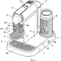
- фиг.1 - общий вид машины приготовления напитков в соответствии с настоящим изобретением;- figure 1 is a General view of a machine for preparing drinks in accordance with the present invention;
- фиг.2 - общий вид подобной машины приготовления напитков в соответствии с настоящим изобретением;- figure 2 is a General view of such a machine for preparing drinks in accordance with the present invention;
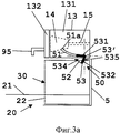
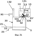
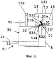
- фиг.3а-3с схематично иллюстрируют виды сбоку разных положений сервисного блока и камеры для ингредиента с блокирующим устройством машины для приготовления напитков в соответствии с настоящим изобретением; и- figa-3c schematically illustrate side views of different positions of the service unit and the chamber for the ingredient with the locking device of the machine for making drinks in accordance with the present invention; and
- фиг.4а-4с схематично иллюстрируют виды спереди блокирующего устройства машины для приготовления напитков, показанные на фиг.3а-3с в соответствующих конфигурациях.- figa-4c schematically illustrate front views of the locking device of the machine for making drinks, shown in figa-3c in the respective configurations.
Осуществление изобретенияThe implementation of the invention
На фиг.1 показана машина приготовления напитков в соответствии с настоящим изобретением. Машина имеет блок приготовления напитка 2 в корпусе 9. Блок 2 сформирован для приема капсулы с ингредиентом в камеру извлечения и для подачи жидкости, такой как вода, в капсулу. Блок 2 монтируется на платформу 1 и продолжается вдоль ее боковой стороны Г. Разливочное отверстие 95 для разлива напитка из блока 2 продолжается через переднюю панель 94 корпуса 9.1 shows a beverage preparation machine in accordance with the present invention. The machine has a
Блок 2 включает заваривающий модуль, который содержит отверстие и закрывающую ручку 11, и держатель ингредиента (не показан) для хранения содержащей вещество капсулы, например капсулы с кофе, и средство подачи напитка, такое как разливочное отверстие 95. Держатель ингредиента обычно содержит держатель капсулы и заварочную сетку, разграничивающую камеру извлечения, систему впрыска жидкости для впрыска воды в капсулу, и устройство закрывания, такое как рычаг, и механизм шарнирного соединения. Соответствующие модули извлечения, например, раскрываются в ЕР 1859713. Следующие возможные признаки блока 2 обсуждаются подробнее в находящейся совместно на рассмотрении заявке ЕР 2070454, содержимое которой настоящим включается посредством ссылки.
Кроме того, в корпусе 9 в местоположении 5 находится сервисный блок 20, 30 для сбора использованных материалов, таких как отработанная жидкость и/или использованный ингредиент напитка. Сервисный блок 20, 30 вручную вставляется в местоположение 5 до положения сбора для сбора использованных материалов (как показано на фиг.1); и удаляется из местоположения 5 для извлечения использованных материалов при их накоплении (как показано на фиг.2). Сервисный блок 20, 30 может задвигаться в местоположение 5 и выдвигаться из местоположения 5.In addition, in the
Данный сервисный блок включает приемник 30 для использованных капсул, который имеет переднюю панель 31 и съемно вставляется под заваривающее устройство и отверстие 95. Подробно детали сервисного блока 20, 30 и его местоположения в корпусе 9 будут описываться со ссылкой на фиг.2-4с.This service unit includes a
На платформе 1 располагается блок 2 напитка, емкость для воды 7, крепящаяся к базовой платформе снаружи к корпусу 9 и смежно с задней стенкой корпуса 9, соединение по жидкости между ними и электрическое соединение к сети питания.On the
Основной выключатель 3 устанавливается на платформе 1 для включения и выключения машины. Две кнопки пользователя 12, обычно для выбора малого и большого количества приготавливаемого напитка, располагаются над блоком 2.The
Верхняя панель 34 платформы 1 имеет устройство в форме соединителя STRIX™ (не показано) для подключения вспенивателя молока 8. Такие разъединяемые соединители для такой платформы 1 и вспениватель 8 раскрываются более подробнее, например, в WO 03/075629, WO 2008/046837 и в WO 2008/142154, содержимое которых настоящим включается посредством ссылки.The
Верхняя панель 34 находится смежно с соседней передней панелью 35, которая может быть соединена с нагревательной системой, в частности, встроенной в платформу 1, и которая может быть сформирована как опора для одной или более чашек или кружек для их предварительного нагрева перед употреблением.The
Как указывалось выше, блок напитка 2 в целом продолжается вверх в пределах корпуса 9 смежно с первой боковой кромкой 1' платформы 1. Вспениватель 8 в целом располагается смежно со второй боковой кромкой платформы 1, противоположной первой кромке 1" так, что корпус 9 и платформа 1 в целом образуют в поперечном сечении Г-образную форму, которая поддерживает вспениватель 8.As indicated above, the
Машина приготовления напитков также включает опорное устройство 6 для опоры кружек, которое располагается под отверстием 95 и имеет форму перфорированной пластины для удаления жидкости. Устройство сбора 6а в форме неглубокой емкости располагается под опорным устройством 6 для сбора удаляемой жидкости. Устройство сбора 6а не должно иметь большую емкость для сбора жидкости. Большее количество времени устройство сбора 6а должно собирать только капли и проливы.The beverage preparation machine also includes a
Опорное устройство 6 и устройство сбора 6а отделяются блоком от платформы 1, например, для слива устройства сбора 6а и/или для чистки.The supporting
Кроме того, сервисный блок 20, 30 имеет опорное устройство 20 для чашки, которое включает, выше опорного устройства 6, вторую опорную пластину 21 для поддержки принимающих емкостей, таких как чашки, меньшего размера под отверстием 95. Как и основное опорное устройство 6, вторая опорная пластина 21 содержит перфорированную пластину для удаления жидкости, в частности в устройство сбора 6а, дополнительно через опорное устройство 6. Вторая опорная пластина 21 перемещается в целом в горизонтальном рабочем положении между отверстием 95 и опорным устройством 6, как иллюстрируется, и перемещается в целом вверх или в вертикальное исходное положение на некоторое расстояние от них с тем, чтобы приемная емкость большего размера могла устанавливаться на опорном устройстве 6 под отверстием 95. Вторая опорная пластина 21, в частности, вращается и/или сдвигается из своего рабочего положения в свое исходное положение. Дополнительные детали возможных признаков такого второго опорного устройства раскрываются, например, в ЕР 1867260.In addition, the
На фиг.2, на которой те же цифровые ссылки указывают в целом на те же элементы, в целом показана другая машина приготовления напитков в соответствии с настоящим изобретением.2, in which the same digital references generally point to the same elements, a whole different beverage preparation machine according to the present invention is generally shown.
Машина приготовления, показанная на фиг.2, имеет те же признаки, что и машина фиг.1 за исключением отсутствия бокового расширения платформы, поддерживающего вспениватель молока.The cooking machine shown in FIG. 2 has the same features as the machine of FIG. 1 except for the lack of lateral expansion of the platform supporting the milk frother.
Данная машина имеет местоположение 5 для размещения сервисного блока 20, 30, которое включает опорное устройство 20 для чашки, на которое опирается приемник 30, имеющий полость 30', которая образует место хранения для сбора использованных капсул под заваривающим устройством с камерой извлечения.This machine has a
Приемник 30 может быть собран к опорному устройству 20 для чашек, которое включает элемент опоры 21 чашки, который шарнирно монтируется на емкость 22, поддерживающую приемник 30. Элемент опоры 21 монтируется к стопору 24 или как единое целое со стопором 24, который вращается с элементом опоры относительно передней панели емкости 22 для остановки направленного книзу вращения элемента опоры 21 и закрепления элемента 21 в горизонтальном положении.The
Приемник 30 может иметь нижнюю часть со сливным отверстием с тем, чтобы емкость 22 могла собирать жидкость, сливаемую из данной нижней части в емкость 22 через сливное отверстие. Опорное устройство 20 для чашек и приемник 30, опирающийся на него, могут вставляться в местоположение 5 единым блоком и удаляться из него.The
Кроме того, приемник 30 имеет отверстие 33 в задней вертикальной стенке, которое используется для предотвращения забивания накоплением использованных капсул, как подробнее описывается в WO 2009/074559, настоящим включенных посредством ссылки.In addition, the
Также показанное на фиг.2 устройство сбора 6а, поддерживающее опорное устройство 6, может сниматься и собираться через механический соединитель 4 к платформе 1.Also shown in FIG. 2, a
Сервисный блок 20, 30 содержит устройство для сбора: отработанной исходной жидкости для напитка, такой как вода, в емкости 22; отработанного исходного твердого материала для напитка, такого как использованный ароматизирующий ингредиент напитка, в частности молотый кофе, дополнительно содержащийся в предварительно разделенной на порции капсуле, в приемнике 30 использованных ингредиентов; и использованного напитка, такого как капли из разливочного отверстия в емкости 22 через канавку удаления жидкости в поддоне для чашек 21.The
Машины приготовления напитков, показанные на фиг.1 и 2, имеют механическое блокирующее устройство 50, включающее блокирующее устройство 53, размещаемое в местоположении 5 и соединенное с взаимодействующими участками 51, 52, 534, 535 держателя ингредиента 13, сервисного блока 20, 30 и местоположения 5.The beverage machines shown in FIGS. 1 and 2 have a
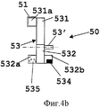
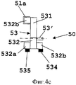
На фиг.3а-4с данный аспект настоящего изобретения иллюстируется подробнее. В частности, на фиг.4а-4с показан вид спереди механического блокирующего устройства 53 в каждом положении блокирующего устройства, иллюстрированного на фиг.3а-3с соответственно, в комбинации с сервисным блоком 20, 30 и держателем ингредиента в форме заваривающего устройства 13, имеющего камеру извлечения 14.3a-4c, this aspect of the present invention is illustrated in more detail. In particular, FIGS. 4a-4c show a front view of a
Машина приготовления напитков имеет заваривающее устройство 13 с фиксированной передней частью 132 и подвижной задней частью 131, разграничивающих камеру с ингредиентом 14 для размещения капсул с ингредиентом. Камера 14 находится в соединении по жидкости с линией впрыска жидкости 15 и разливочным отверстием 95. Заваривающее устройство 13 имеет конфигурацию перемещения, в которой камера ингредиента 14 открыта, как иллюстрируется на фиг.3b, и конфигурацию обработки, в которой камера 14 закрыта, как показано на фиг.3а. Камера 14 открывается и закрывается раздвиганием и сдвиганием передней части 132 и задней части 131 заваривающего устройства 13. Точнее говоря, задняя часть 131 образует подвижную первую часть, а передняя часть 132 образует фиксированную вторую часть заваривающего устройства 13. Ручка 11, как иллюстрируется на фиг.1 и 2, может предусматриваться для открывания и закрывания вручную заваривающего устройства 13.The beverage preparation machine has a
Такой механизм ручного открывания и закрывания заваривающего устройства вместе с вставкой, извлечением и удалением капсул с ингредиентом подробно описывается, например, в ЕР 1646305, ЕР 1757212, ЕР 1859713, ЕР 1859714, ЕР 2103236, ЕР 2119385, WO 2009/043630 и WO 2009/130099, содержимое которых настоящим включается посредством ссылки.Such a mechanism for manually opening and closing the brewing device together with the insertion, extraction and removal of the capsules with the ingredient is described in detail, for example, in EP 1646305, EP 1757212, EP 1859713, EP 1859714, EP 2103236, EP 2119385, WO 2009/043630 and WO 2009 / 130099, the contents of which are hereby incorporated by reference.
Кроме того, иллюстрируемая машина приготовления напитков содержит механическое устройство блокирования 50 с блокирующим устройством 53 для механического препятствования приготовлению напитка, когда сервисный блок 20, 30 находится не в позиции сбора. В частности, механическое блокирующее устройство 53 может быть устроено для препятствования: закрытия камеры ингредиента 14, когда сервисный блок 20, 30 находится не в позиции сбора, как иллюстрируется на фиг.3с; и/или предотвращения извлечения сервисного блока 20, 30, когда камера ингредиента 14 не находится в открытой конфигурации, как иллюстрируется на фиг.3а.In addition, the illustrated beverage preparation machine comprises a
Когда заваривающее устройство 13 открывается или закрывается вручную ручкой, блокирующее устройство 53 в устройстве блокирования 50 блокирует или освобождает заваривающее устройство и ручку в зависимости от положения сервисного блока 20, 30.When the
Механическое устройство блокирования 50 содержит первый кулачок 51, например канавку, соединенную с подвижной задней частью 131 заваривающего устройства 13, второй кулачок 52, например канавку, соединенную с сервисным блоком 20, 30 и блокирующим устройством 53, имеющим элементы, приводимые в действие кулачками 531а, 532а, соединенные с кулачками 51, 52. Элемент, приводимый в действие кулачком 531а, образует первый соединительный элемент, соединенный с подвижной первой частью 131 заваривающего устройства 13 через взаимодействующий (встроенный) соединительный элемент, включая кулачок 51 в подвижной первой части 131. Элемент, приводимый в действие кулачком 532а, образует второй соединительный элемент, соединенный или соединяемый с сервисным блоком 20, 30 через взаимодействующий (встроенный) соединительный элемент, включая кулачок 52 в сервисном блоке 20, 30.The
В результате блокирующее устройство 53 имеет пару или соединенные рычаги 531, 532, вращаемые вокруг оси 53' в местоположении 5. Рычаги 531, 532 поддерживают соединительные элементы 531а, 532а, например, в целом в форме штырей, зацепляющихся как элементы, приводимые в действие кулачками, с кулачками 51, 52, например, в форме канавок, взаимодействующих с такими штырями. Вращающаяся ось 53' вставляется в целом в продолговатое удерживающее отверстие (не показано) в местоположении 5 машины приготовления напитков, для обеспечения вращения элемента 53 вокруг оси 53' и малых перемещений оси 53' в местоположении 5, в частности в целом горизонтальных перемещений.As a result, the locking
Первый соединительный элемент 531а так механически соединен с держателем ингредиента 13, что переход держателя ингредиента 13 из его конфигурации обработки (фиг.3а и 4а) в его конфигурацию перемещения (фиг.3b и 4b) и наоборот вызывает движение первого и второго соединительных элементов 531a, 532а. Второй соединительный элемент 532а так механически соединен или соединяется с сервисным блоком (20, 30), что перемещение сервисного блока (20, 30) из его рабочего положения и в его рабочее положение (фиг.3а) в местоположении 5 вызывает движение второго и первого соединительных элементов.The first connecting
На фиг.3а и 4а иллюстрируется запорное устройство 50, когда камера извлечения 14 находится в закрытом состоянии, т.е. передняя и задняя части 131, 132 заваривающего устройства 13 соединены вместе и находятся в конфигурации обработки. В данной конфигурации машина приготовления напитков готова к приготовлению напитка при условии, что капсула находится в камере извлечения 14. В такой конфигурации сервисный блок 20, 30 не должен извлекаться из местоположения 5. Для предотвращения такого выдвижения запорное устройство 53 имеет рычаг 532 с элементом 532а, полностью зацепленным с кулачком 52, соединенным с сервисным блоком 20, 30. Если потребитель тянет на себя сервисный блок 20, 30, запорное устройство 53, которое имеет другой рычаг 531 с элементом 531а, зацепленным в кулачке 51, и вращающуюся ось 53', зацепленную в соответствующее отверстие в местоположении 5, не дает извлечь сервисный блок 20, 30, так как запорное устройство 53 не может вращаться.Figures 3a and 4a illustrate a
В результате в соответствии с настоящим изобретением запорное устройство 53 механически определяет конфигурацию заваривающего устройства 13 и механически препятствует извлечению сервисного блока 20, 30 из местоположения 5, когда заваривающее устройство 13 находится в конфигурации обработки, а именно когда заваривающее устройство 13 отключено от конфигурации перемещения.As a result, in accordance with the present invention, the locking
На фиг.3b и 4b иллюстрируется камера извлечения 14 в конфигурации перемещения, т.е. передняя и задняя части 131, 132 заваривающего устройства 13 расположены на расстоянии друг от друга. В данной конфигурации машина приготовления напитков не находится в состоянии готовности к приготовлению напитка. В такой конфигурации можно вставить капсулу в заварочную камеру 14 или извлечь капсулу из нее. Кроме того, в данной нерабочей конфигурации сервисный блок 20, 30 можно извлечь из местоположения 5. В результате на фиг.3b и 4b иллюстрируется переходная конфигурация.3b and 4b illustrate the
Запорное устройство 53 имеет свой рычаг 531 с приводимым вверх элементом 531а кулачком 51, соединенным с заваривающим устройством 13. Кроме того, рычаг 532 с элементом 532а отцепляются от кулачка 52, соединенного с сервисным блоком 20, 30. Если потребитель тянет к себе сервисный блок 20, 30, запорное устройство 53 больше не блокирует извлечение блока 20, 30 из местоположения 5. В данном случае устройство блокирования 50 перемещается в конфигурацию, показанную на фиг.3с и 4с.The locking
И наоборот, если вместо извлечения сервисного блока 20, 30 из местоположения 5 задняя часть 131 заваривающего устройства 13 перемещается к передней части 132, запорное устройство 53 вращается вокруг оси 53' с его рычагом 532 и элементом 532а, зацепляющимся с кулачком 52 сервисного блока 20, 30 по направлению к конфигурации, иллюстрированной на фиг.3а и 4а.Conversely, if instead of removing the
На фиг.3с и 4с иллюстрируется извлечение сервисного блока 20, 30, когда камера извлечения 14 блокируется в открытой конфигурации, т.е. передняя и задняя части 131 132 заваривающего устройства 13 находятся на расстоянии друг от друга в конфигурации перемещения и не могут приблизиться друг к другу. В такой конфигурации машина приготовления напитков находится не в состоянии готовности к приготовлению напитка, а в состоянии обслуживания, например слива собранной воды и удаления твердого материала ингредиента, такого как молотый кофе, из сервисного блока 20, 30.Figures 3c and 4c illustrate the removal of the
В данной конфигурации запорное устройство 53 было приведено в блокирующую позицию для предотвращения закрытия заварочной камеры 14. Рычаг 531 с элементом 531а приводятся вверх кулачком 51 к его блокирующему концу 51а. Блокирующий конец 51а продолжается в целом вверх в кулачок 51 и меняет направление. Кроме того, рычаг 532 имеет закрепляющий элемент 532b, противоположный элементу 532а. Закрепляющий элемент 532b крепится на фиксаторе 534 и напротив фиксатора 534 местоположения 5. Для перевода закрепляющего элемента 532b на фиксатор 534 сервисный блок 20, 30 имеет направляющий элемент 535, например выступ, который направляет запорное устройство 53 через рычаг 532 в проходе приводного элемента 535, когда сервисный блок 20, 30 выталкивается из местоположения 5. Приведением рычага 532 на опорную поверхность 534 вращающаяся ось 53' немного смещается вперед с приводным элементом 535. В данной конфигурации запорное устройство фиксируется между опорной поверхностью 534, блокирующим концом 51а и продолговатым отверстием в местоположении 5 для приема оси 53'. А именно запорное устройство 53 не может вращаться против часовой стрелки, блокируя открытую заднюю часть 131 заваривающего устройства 13, в результате напиток не выводится из сервисного блока 20, 30 в его нормальном рабочем положении в местоположении 5.In this configuration, the locking
В результате в соответствии с настоящим изобретением запорное устройство 53 сформировано для механического определения положения сервисного блока 20, 30 и механического предотвращения от перехода держателя ингредиента 13 в его конфигурацию обработки, когда сервисный блок 20, 30 отключен от своего рабочего положения, а именно когда сервисный блок вынут из местоположения 5.As a result, in accordance with the present invention, the locking
Вообще говоря, машина может быть устроена для отключения одного или более компонентов, необходимых для обработки ингредиента, когда держатель ингредиента 13 не находится в конфигурации обработки. В такой ситуации машина может отключить насос прокачки жидкости, такой как вода, через ингредиент.Generally speaking, a machine may be arranged to shut off one or more components necessary for processing an ingredient when the
Когда сервисный блок 20, 30 вставляется обратно в рабочее положение, направляющий элемент 535 сервисного блока 20, 30 входит в контакт с элементом 532а запорного устройства 53 и отталкивает элемент 532b от фиксатора 534 в конфигурацию, показанную на фиг.3b и 4b. Для того, чтобы такое отсоединение произошло, верхний конец направляющего элемента 535 располагается немного выше, чем нижний конец элемента 532а, когда элемент 532b опирается на опорную поверхность 534. В результате направляющий элемент 535 используется для закрепления и раскрепления запорного устройства 53 в обоих направлениях при проходе под запорным устройством 53.When the
В закрепленной позиции, как показано на фиг.3с и 4с, запорное устройство 53 может располагаться неплотно соединенным между блокирующим концом 51а, фиксатором 534 и продолговатым отверстием в местоположении 5 для фиксирующей оси 53', или запорное устройство 53 может быть подогнано между ними для правильной фиксации элемента 53 в данном положении в случае перемещения машины приготовления напитков в процессе извлечения сервисного блока 20, 30. Когда запорное устройство 53 сконфигурировано для размещения в данном положении, по меньшей мере, один или оба рычага 531, 532 могут быть немного упругими.In the fixed position, as shown in FIGS. 3c and 4c, the locking
Первый и второй соединительные элементы 531а, 532а в целом жестко взаимно соединены рычагами 531, 532. Запорное устройство 53, включающее закрепляющий элемент 532b и ось 53', может быть сформировано из одного компонента, с которым первый и второй соединительный элементы 531a, 532а составляют единое целое. Например, запорное устройство сформировано как единое целое формованием или машинной обработкой.The first and second connecting
В одном варианте, конечно, можно предложить такой тип конфигурации с заваривающим устройством, в котором передняя часть движется к задней части и от задней части для открывания и закрывания заварочной камеры, например, как указывается в WO 2009/043630. В данном случае запорное устройство следует за кулачком, соединенным с подвижной передней частью заваривающего устройства.In one embodiment, of course, it is possible to propose a type of configuration with a brewing device in which the front part moves towards the rear and from the rear to open and close the brewing chamber, for example, as indicated in WO 2009/043630. In this case, the locking device follows the cam connected to the movable front of the brewing device.
Claims (15)
- местоположение (5);
- держатель ингредиента (13), который имеет конфигурацию обработки для обработки ингредиента, содержащегося в держателе, и конфигурацию перемещения для вставки указанного ингредиента в держатель и/или извлечения указанного ингредиента из держателя; и
- сервисный блок (20, 30), имеющий рабочее положение в местоположении для сбора использованного ингредиента из держателя ингредиента и/или для подачи потребляемого ингредиента в держатель ингредиента, сервисный блок извлекается из местоположения для удаления использованного ингредиента и/или заполнения потребляемым ингредиентом,
отличающаяся тем, что механическое запорное устройство (53) предусматривается для:
- механического определения положения сервисного блока и механического предотвращения держателя ингредиента от перехода в конфигурацию обработки, когда сервисный блок отключен от своего рабочего положения, а именно когда сервисный блок извлечен из местоположения; и/или
- механического определения конфигурации держателя ингредиента и механического предотвращения извлечения сервисного блока из местоположения, когда держатель ингредиента находится в конфигурации обработки, а именно когда держатель ингредиента отключен от своей конфигурации перемещения.1. A beverage preparation machine comprising:
- location (5);
an ingredient holder (13), which has a processing configuration for processing an ingredient contained in the holder and a movement configuration for inserting said ingredient into the holder and / or removing said ingredient from the holder; and
- a service unit (20, 30) having a working position at the location for collecting the used ingredient from the ingredient holder and / or for supplying the consumed ingredient to the ingredient holder, the service unit is removed from the location to remove the used ingredient and / or filling with the consumed ingredient,
characterized in that the mechanical locking device (53) is provided for:
- mechanically determining the position of the service unit and mechanically preventing the ingredient holder from moving to the processing configuration when the service unit is disconnected from its operating position, namely when the service unit is removed from the location; and / or
- mechanically determining the configuration of the ingredient holder and mechanically preventing the service unit from being removed from the location when the ingredient holder is in the processing configuration, namely when the ingredient holder is disconnected from its movement configuration.
- блокирования подвижной первой части от перемещения в конфигурацию обработки, когда определяется, что сервисный блок (20, 30) отключен от своего рабочего положения запорным устройством; и/или
- определения, когда подвижная первая часть находится в конфигурации обработки с тем, чтобы блокировать сервисный блок в его рабочем положении запорным устройством.3. The machine according to claim 2, in which the mechanical locking device (53) comprises a first connecting element (531a) connected to the movable first part (131), the first connecting element is additionally connected to the movable first part by the cam device and the actuated element cam (51, 531a), the first connecting element is formed for:
- blocking the movable first part from moving to the processing configuration when it is determined that the service unit (20, 30) is disconnected from its operating position by a locking device; and / or
- determining when the movable first part is in the processing configuration so as to block the service unit in its operating position by the locking device.
- блокирования сервисного блока в его рабочем положении, когда подвижная первая часть (131) находится в конфигурации обработки; и/или
- определения, когда сервисный блок отключен от своего рабочего положения для блокирования подвижной первой части от перехода в конфигурацию обработки запорным устройством.4. Machine according to any one of claims 1 to 3, in which the mechanical locking device (53) comprises a second connecting element (532a) connected or connected to the service unit (20, 30), the second connecting element is additionally connected to a removable service unit ( 20, 30) by a cam device and an element driven by a cam (52, 532a), a second connecting element is formed for:
- blocking the service unit in its working position when the movable first part (131) is in the processing configuration; and / or
- determining when the service unit is disconnected from its operating position to block the movable first part from moving to the processing configuration by the locking device.
- подачи в держатель ингредиента потребляемой жидкости и/или твердого ингредиента, такого как вода, молоко, листья чая, молотый или растворимый кофе, концентрат или сухой суп, сироп и шоколадный порошок; и/или
- сбора из держателя ингредиента использованной жидкости и/или ингредиента, такого как вода, остатки напитка и/или использованный ингредиент.14. The machine according to item 13, in which the service unit (20, 30) is arranged for:
- feeding the holder of the ingredient of the consumed liquid and / or solid ingredient, such as water, milk, tea leaves, ground or instant coffee, concentrate or dry soup, syrup and chocolate powder; and / or
- collection from the ingredient holder of the used liquid and / or ingredient, such as water, the remainder of the drink and / or the used ingredient.
Applications Claiming Priority (3)
| Application Number | Priority Date | Filing Date | Title |
|---|---|---|---|
| EP10150841 | 2010-01-15 | ||
| EP10150841.4 | 2010-01-15 | ||
| PCT/EP2011/050319 WO2011086088A1 (en) | 2010-01-15 | 2011-01-12 | Ergonomic ingredient holder and service unit coordination |
Publications (2)
| Publication Number | Publication Date |
|---|---|
| RU2012134787A RU2012134787A (en) | 2014-02-20 |
| RU2539670C2 true RU2539670C2 (en) | 2015-01-20 |
Family
ID=42236959
Family Applications (1)
| Application Number | Title | Priority Date | Filing Date |
|---|---|---|---|
| RU2012134787/12A RU2539670C2 (en) | 2010-01-15 | 2011-01-12 | Ergonomic connection of ingredient holder and service unit |
Country Status (12)
| Country | Link |
|---|---|
| US (1) | US20130025465A1 (en) |
| EP (1) | EP2523586B1 (en) |
| JP (1) | JP2013517026A (en) |
| CN (1) | CN102802477B (en) |
| AU (1) | AU2011206624A1 (en) |
| BR (1) | BR112012017529A2 (en) |
| CA (1) | CA2786844A1 (en) |
| ES (1) | ES2505565T3 (en) |
| PT (1) | PT2523586E (en) |
| RU (1) | RU2539670C2 (en) |
| WO (1) | WO2011086088A1 (en) |
| ZA (1) | ZA201206089B (en) |
Families Citing this family (40)
| Publication number | Priority date | Publication date | Assignee | Title |
|---|---|---|---|---|
| RU2702253C2 (en) * | 2010-11-11 | 2019-10-07 | Сосьете Де Продюи Нестле С.А. | Capsule, beverage preparation apparatus and food product preparation system |
| JP2014526325A (en) * | 2011-09-16 | 2014-10-06 | ネステク ソシエテ アノニム | Clean multi-system beverage machine |
| WO2013041580A1 (en) * | 2011-09-22 | 2013-03-28 | Nestec S.A. | Cup support and dispensing device |
| CN104053385B (en) | 2012-01-13 | 2017-05-31 | 雀巢产品技术援助有限公司 | For short cup and the beverage machine of cup high |
| ES2576188T3 (en) | 2012-02-28 | 2016-07-06 | Nestec S.A. | Capsule controlled motorized beverage manufacturing unit |
| US9504348B2 (en) | 2014-03-11 | 2016-11-29 | Starbucks Corporation | Cartridge ejection systems and methods for single-serve beverage production machines |
| US9439532B2 (en) | 2014-03-11 | 2016-09-13 | Starbucks Corporation | Beverage production machines with multi-chambered basket units |
| US20150257586A1 (en) * | 2014-03-11 | 2015-09-17 | Starbucks Corporation Dba Starbucks Coffee Company | Single-serve beverage production machine |
| EP3223667A1 (en) * | 2014-11-27 | 2017-10-04 | Nestec S.A. | Ergonomic handle arrangement |
| PT3232875T (en) * | 2014-12-18 | 2024-07-26 | Nestle Sa | Beverage machine with slidingly connectable cup-support |
| US10342377B2 (en) | 2015-06-16 | 2019-07-09 | Starbucks Corporation | Beverage preparation systems with adaptable brew chambers |
| US10602874B2 (en) | 2015-06-16 | 2020-03-31 | Starbucks Corporation Dba Starbucks Coffee Company | Beverage preparation systems with brew chamber access mechanisms |
| US9968217B2 (en) | 2015-06-16 | 2018-05-15 | Starbucks Corporation | Beverage preparation systems with brew chamber securing mechanisms |
| DE102015214097A1 (en) | 2015-07-24 | 2017-01-26 | BSH Hausgeräte GmbH | Hot beverage preparation device, in particular fully automatic coffee machine |
| DE102016202630A1 (en) * | 2016-02-19 | 2017-08-24 | BSH Hausgeräte GmbH | Hot beverage preparation device with locking elements |
| CN108712872B (en) | 2016-03-02 | 2021-10-12 | 雀巢产品有限公司 | Beverage machine with ergonomic serving unit |
| AU201711148S (en) * | 2016-09-06 | 2017-03-15 | SOCIAƒA©TAƒA© DES PRODUITS NESTLAƒA© S A | A coffee machine |
| ES2893852T3 (en) | 2016-09-09 | 2022-02-10 | Nestle Sa | Ergonomically operated beverage machine |
| AU201711682S (en) * | 2016-09-30 | 2017-04-07 | SOCIAƒA©TAƒA© DES PRODUITS NESTLAƒA© S A | A coffee machine |
| CA3041722A1 (en) | 2016-11-09 | 2018-05-17 | Pepsico, Inc. | Carbonated beverage makers, methods, and systems |
| US10898031B2 (en) * | 2016-11-16 | 2021-01-26 | F'real Foods Llc | Modular blender with improved water heating and light beam detection |
| CN110678107B (en) | 2017-06-01 | 2023-03-14 | 雀巢产品有限公司 | Beverage machine with stabilizing foot |
| CN110662469B (en) | 2017-06-01 | 2023-03-14 | 雀巢产品有限公司 | Beverage machine with storable dispensing head |
| EP3629858A1 (en) | 2017-06-01 | 2020-04-08 | Société des Produits Nestlé S.A. | Beverage machine with ergonomic power switch |
| EP3629853A1 (en) | 2017-06-01 | 2020-04-08 | Société des Produits Nestlé S.A. | Beverage machine with a collapsible interface |
| AU2018283446B2 (en) | 2017-06-13 | 2024-06-27 | Societe Des Produits Nestle S.A. | Beverage preparation machine with capsule recognition |
| WO2019057619A1 (en) | 2017-09-25 | 2019-03-28 | Nestec Sa | Beverage machines with modularity |
| WO2019057618A1 (en) | 2017-09-25 | 2019-03-28 | Nestec Sa | Beverage machines with a removable module |
| CN111655093B (en) | 2018-02-09 | 2023-01-10 | 雀巢产品有限公司 | Machine for preparing and dispensing beverages |
| EP3764850A1 (en) | 2018-03-14 | 2021-01-20 | Société des Produits Nestlé S.A. | Beverage machine with a non-homogeneous ingredient extraction configuration |
| US20210000288A1 (en) | 2018-03-14 | 2021-01-07 | Societe Des Produits Nestle S.A. | Beverage machine with a partly closed dispensing face |
| CA3093735A1 (en) | 2018-03-14 | 2019-09-19 | Societe Des Produits Nestle S.A. | Beverage machine with a controlled capsule piercing |
| EP3764851B1 (en) | 2018-03-14 | 2023-05-10 | Société des Produits Nestlé S.A. | Beverage machine with a controlled outflow aperture |
| CN112512390B (en) | 2018-08-09 | 2023-08-25 | 雀巢产品有限公司 | Cup support easy to insert |
| JP7382398B2 (en) | 2018-09-27 | 2023-11-16 | ソシエテ・デ・プロデュイ・ネスレ・エス・アー | Beverage machine adaptive service unit |
| PT3855986T (en) | 2018-09-27 | 2023-09-11 | Nestle Sa | Beverage machine with an actuation distribution |
| EP3628195A1 (en) | 2018-09-27 | 2020-04-01 | Société des Produits Nestlé S.A. | Beverage preparation machine with recipient detection |
| CN113163978B (en) | 2018-12-12 | 2023-09-22 | 雀巢产品有限公司 | Beverage preparation machine with capsule recognition |
| US20230038172A1 (en) | 2020-02-05 | 2023-02-09 | Societe Des Produits Nestle S.A. | Beverage preparation machine with capsule recognition |
| JP2023512515A (en) | 2020-02-05 | 2023-03-27 | ソシエテ・デ・プロデュイ・ネスレ・エス・アー | Beverage preparation machine that recognizes capsules |
Citations (4)
| Publication number | Priority date | Publication date | Assignee | Title |
|---|---|---|---|---|
| WO1990014014A1 (en) * | 1989-05-16 | 1990-11-29 | Food Equipment Technologies Company, Inc. | Semiautomatic beverage maker and method |
| RU2223691C2 (en) * | 2000-09-28 | 2004-02-20 | Катаока Буссан Кабусики Каиса | Filtering device for coffee and like beverages |
| RU2331349C2 (en) * | 2003-01-24 | 2008-08-20 | Крафт Фудз Р Унд Д, Инк. | Beverage-making machine |
| CN101554290A (en) * | 2009-05-13 | 2009-10-14 | 广东新宝电器股份有限公司 | Self-locking device for coffee machine brewing device |
Family Cites Families (52)
| Publication number | Priority date | Publication date | Assignee | Title |
|---|---|---|---|---|
| FR2524790B1 (en) * | 1982-04-09 | 1986-07-25 | Moulinex Sa | HOUSEHOLD COFFEE MAKER |
| US4833978A (en) * | 1988-07-06 | 1989-05-30 | Black & Decker, Inc. | Intelligent coffee brewing system |
| US5331885A (en) * | 1988-07-27 | 1994-07-26 | Food Equipment Technologies Company, Inc. | Semiautomatic beverage maker and method |
| US4960309A (en) | 1988-11-29 | 1990-10-02 | Steelcase Inc. | Drawer lock and interlock mechanism |
| US5056876A (en) | 1988-11-29 | 1991-10-15 | Steelcase Inc. | Drawer lock and interlock mechanism |
| US5465650A (en) * | 1995-01-11 | 1995-11-14 | Bunn-O-Matic Corporation | Combo grinder and brewer |
| DE69920230T2 (en) | 1999-10-28 | 2005-04-28 | Société des Produits Nestlé S.A. | Ejector for cartridge |
| US6459854B1 (en) | 2000-01-24 | 2002-10-01 | Nestec S.A. | Process and module for heating liquid |
| US6439105B1 (en) * | 2000-07-31 | 2002-08-27 | Bunn-O-Matic Corporation | Multiple direction holder and beverage making apparatus |
| CA2335420A1 (en) * | 2001-02-12 | 2002-08-12 | Pierre Mercier | Method and apparatus for the preparation of hot beverages |
| US7013795B2 (en) * | 2002-01-10 | 2006-03-21 | Conair Corporation | Grind and brew coffee apparatus |
| US6831839B2 (en) | 2002-02-28 | 2004-12-14 | Netezza Corporation | Adjustable sled module for mass storage devices |
| DK1380243T3 (en) | 2002-07-12 | 2008-08-25 | Nestec Sa | Device for heating a liquid |
| FR2842091B1 (en) * | 2002-07-12 | 2004-11-19 | Seb Sa | COFFEE MACHINE COMPRISING AN IMPROVED LOCKING DEVICE |
| US8621980B2 (en) * | 2002-07-16 | 2014-01-07 | Bunn-O-Matic Corporation | Temperature control system |
| US7316178B2 (en) * | 2003-01-24 | 2008-01-08 | Kraft Foods R & D, Inc. | Machine for the preparation of beverages |
| US7607385B2 (en) * | 2003-01-24 | 2009-10-27 | Kraft Foods R & D, Inc. | Machine for the preparation of beverages |
| US7255039B2 (en) * | 2003-01-24 | 2007-08-14 | Kraft Foods R & D, Inc. | Machine for the preparation of beverages |
| US7231869B2 (en) * | 2003-01-24 | 2007-06-19 | Kraft Foods R & D Inc. | Machine for the preparation of beverages |
| DE20302410U1 (en) | 2003-02-13 | 2004-06-24 | Nestec S.A. | Capsule magazine unit with capsule magazine unit receiving device, in particular an espresso machine |
| EP1495702A1 (en) | 2003-07-10 | 2005-01-12 | Nestec S.A. | Device for the extraction of a cartridge |
| US7093533B2 (en) * | 2003-10-10 | 2006-08-22 | Applica Consumer Products, Inc. | Brewing apparatus hot water discharge head |
| CA2555318A1 (en) * | 2004-02-06 | 2005-08-25 | Bunn-O-Matic Corporation | Apparatus, system and method for retaining beverage brewing substance |
| GB2411105B (en) * | 2004-02-17 | 2006-08-30 | Kraft Foods R & D Inc | An insert and a system for the preparation of beverages |
| FR2873011B1 (en) * | 2004-07-16 | 2007-12-14 | Reneka Internat Sarl | PREPARATION GROUP OF AT LEAST ONE EXPRESSO TYPE COFFEE CUP OR OTHER HOT BEVERAGE FROM A PREEMBALLED INDIVIDUAL DOSE CALLED DOSETTE |
| GB2416480B (en) * | 2004-07-27 | 2007-12-27 | Kraft Foods R & D Inc | A system for the preparation of beverages |
| US7219596B2 (en) * | 2004-08-19 | 2007-05-22 | Carrier Commerical Refrigeration, Inc. | Coffee brewer with loading and ejection mechanism for a coffee cartridge |
| EP1634520A1 (en) | 2004-09-13 | 2006-03-15 | Nestec S.A. | Device and method for heating a liquid |
| US8881642B2 (en) * | 2004-10-15 | 2014-11-11 | Bunn-O-Matic Corporation | Brewer calibration system |
| FR2878721B1 (en) * | 2004-12-06 | 2009-04-17 | Seb Sa | AUTOMATIC INFUSION BEVERAGE DISPENSER COMPRISING A INFUSE DEVICE EXPULSION DEVICE |
| US7648049B1 (en) * | 2005-04-19 | 2010-01-19 | Food Equipment Technologies Company, Inc. | Beverage ingredient mixing drink dispenser |
| ATE397878T1 (en) | 2005-06-07 | 2008-07-15 | Nestec Sa | BEVERAGE MACHINE WITH COLLECTION TANK FOR CONTAINERS OF DIFFERENT HEIGHTS |
| CN2920114Y (en) * | 2005-08-15 | 2007-07-11 | 王冬雷 | Coffee-making machine brewing locking device |
| DE102005040525A1 (en) * | 2005-08-26 | 2007-03-01 | BSH Bosch und Siemens Hausgeräte GmbH | Kitchen appliance with safety system and method for operating a kitchen appliance |
| ATE470384T1 (en) | 2005-09-20 | 2010-06-15 | Nestec Sa | THERMOBLOCK BASED BEVERAGE PRODUCTION DEVICE WITH A BREWING CHAMBER |
| ES2332378T3 (en) | 2006-05-24 | 2010-02-03 | Nestec S.A. | INFUSION DEVICE FOR CAPSULE WITH VARIABLE TRANSMISSION RELATIONSHIP CLOSURE MECHANISM. |
| DE602006005343D1 (en) | 2006-05-24 | 2009-04-09 | Nestec Sa | Brewing device and capsule system with a capsule holder for simplified introduction and removal of the capsule |
| PL2189088T3 (en) | 2006-06-16 | 2013-10-31 | Nestec Sa | Beverage distribution apparatus with support system and droplet recuperation for containers with different sizes |
| FR2902629B1 (en) * | 2006-06-26 | 2010-12-17 | Seb Sa | PULVERULENT PRODUCT DISPENSER WITH REMOVABLE TANK |
| ITMI20061307A1 (en) * | 2006-07-06 | 2008-01-07 | Perfect Steam Appliances Ltd | INFUSION GROUP FOR MACHINE FOR THE PREPARATION OF DRINKS |
| EP2059156B1 (en) * | 2006-09-07 | 2010-04-21 | Keurig, Incorporated | Method and apparatus for beverage formation |
| EP1914495A1 (en) | 2006-10-20 | 2008-04-23 | Nestec S.A. | Apparatus for cooling of a fluid food preparation |
| WO2008142154A1 (en) | 2007-05-23 | 2008-11-27 | Nestec S.A. | Appliance for conditioning a milk-based liquid |
| ITFI20070172A1 (en) | 2007-07-24 | 2009-01-25 | Saeco Ipr Ltd | "A SUPPORT FOR CUPS OR OTHER CONTAINERS IN DRINK MACHINES" |
| WO2009043630A2 (en) | 2007-10-04 | 2009-04-09 | Nestec S.A. | Beverage brewing unit |
| EP2070454B1 (en) | 2007-12-12 | 2015-07-15 | Nestec S.A. | Beverage production machines comprising a plurality of core units |
| CA2707854C (en) * | 2007-12-12 | 2016-02-02 | Nestec S.A. | Used capsule or pod receptacle for liquid food or beverage machines |
| ES2381210T3 (en) * | 2007-12-18 | 2012-05-24 | Nestec S.A. | System for the preparation of a beverage from ingredients provided by an encoded insert |
| CN101951820B (en) * | 2008-02-05 | 2013-10-09 | 卢易吉拉瓦赞有限公司 | Granular infusion cartridge loading and ejecting device and related beverage dispensing machine |
| RU2497429C2 (en) | 2008-04-22 | 2013-11-10 | Нестек С.А. | Modula design device for preparation of beverages |
| MX2010011993A (en) * | 2008-04-30 | 2010-11-30 | Bunn O Matic Corp | Brewer including substance removal assembly. |
| US8695484B2 (en) | 2008-05-07 | 2014-04-15 | Nestec S.A. | Used capsule collector for beverage devices |
-
2011
- 2011-01-12 CA CA2786844A patent/CA2786844A1/en not_active Abandoned
- 2011-01-12 WO PCT/EP2011/050319 patent/WO2011086088A1/en active Application Filing
- 2011-01-12 EP EP11700170.1A patent/EP2523586B1/en not_active Not-in-force
- 2011-01-12 AU AU2011206624A patent/AU2011206624A1/en not_active Abandoned
- 2011-01-12 BR BR112012017529A patent/BR112012017529A2/en not_active IP Right Cessation
- 2011-01-12 JP JP2012548416A patent/JP2013517026A/en not_active Ceased
- 2011-01-12 US US13/522,259 patent/US20130025465A1/en not_active Abandoned
- 2011-01-12 ES ES11700170.1T patent/ES2505565T3/en active Active
- 2011-01-12 PT PT117001701T patent/PT2523586E/en unknown
- 2011-01-12 RU RU2012134787/12A patent/RU2539670C2/en not_active IP Right Cessation
- 2011-01-12 CN CN201180013899.5A patent/CN102802477B/en not_active Expired - Fee Related
-
2012
- 2012-08-14 ZA ZA2012/06089A patent/ZA201206089B/en unknown
Patent Citations (4)
| Publication number | Priority date | Publication date | Assignee | Title |
|---|---|---|---|---|
| WO1990014014A1 (en) * | 1989-05-16 | 1990-11-29 | Food Equipment Technologies Company, Inc. | Semiautomatic beverage maker and method |
| RU2223691C2 (en) * | 2000-09-28 | 2004-02-20 | Катаока Буссан Кабусики Каиса | Filtering device for coffee and like beverages |
| RU2331349C2 (en) * | 2003-01-24 | 2008-08-20 | Крафт Фудз Р Унд Д, Инк. | Beverage-making machine |
| CN101554290A (en) * | 2009-05-13 | 2009-10-14 | 广东新宝电器股份有限公司 | Self-locking device for coffee machine brewing device |
Also Published As
| Publication number | Publication date |
|---|---|
| CN102802477A (en) | 2012-11-28 |
| AU2011206624A1 (en) | 2012-08-02 |
| ES2505565T3 (en) | 2014-10-10 |
| CN102802477B (en) | 2014-12-03 |
| CA2786844A1 (en) | 2011-07-21 |
| EP2523586A1 (en) | 2012-11-21 |
| PT2523586E (en) | 2014-09-09 |
| JP2013517026A (en) | 2013-05-16 |
| EP2523586B1 (en) | 2014-08-13 |
| BR112012017529A2 (en) | 2019-09-24 |
| ZA201206089B (en) | 2014-01-29 |
| US20130025465A1 (en) | 2013-01-31 |
| RU2012134787A (en) | 2014-02-20 |
| WO2011086088A1 (en) | 2011-07-21 |
Similar Documents
| Publication | Publication Date | Title |
|---|---|---|
| RU2539670C2 (en) | Ergonomic connection of ingredient holder and service unit | |
| EP2523587B1 (en) | Ergonomic service unit for beverage preparation machines | |
| RU2563214C2 (en) | Ergonomic service device for beverage making machine | |
| EP2592980B1 (en) | Secure cup support for beverage machine | |
| US8002146B2 (en) | Drink dispensing device with holding and drip-collecting system for receptacles of different sizes | |
| RU2501513C2 (en) | Machine for making liquid food or beverages with drip tray and support for cups | |
| RU2617365C9 (en) | Beverage preparation machine for low and high cups | |
| JP2017140415A (en) | Beverage machine with cover for ingredient inlet | |
| US20100251900A1 (en) | Used capsule or pod receptacle for liquid food or beverage machines | |
| CN111655092A (en) | Used capsule receptacle for beverage machine | |
| RU2778826C2 (en) | A device for making a beverage with convenient spillage prevention | |
| CZ20001711A3 (en) | Percolator system |
Legal Events
| Date | Code | Title | Description |
|---|---|---|---|
| MM4A | The patent is invalid due to non-payment of fees |
Effective date: 20160113 |