EP2173275B1 - Apparatus for the treatment of stress urinary incontinence - Google Patents
Apparatus for the treatment of stress urinary incontinence Download PDFInfo
- Publication number
- EP2173275B1 EP2173275B1 EP08796887.1A EP08796887A EP2173275B1 EP 2173275 B1 EP2173275 B1 EP 2173275B1 EP 08796887 A EP08796887 A EP 08796887A EP 2173275 B1 EP2173275 B1 EP 2173275B1
- Authority
- EP
- European Patent Office
- Prior art keywords
- sling
- suture
- needle
- practitioner
- end portion
- Prior art date
- Legal status (The legal status is an assumption and is not a legal conclusion. Google has not performed a legal analysis and makes no representation as to the accuracy of the status listed.)
- Active
Links
- 206010066218 Stress Urinary Incontinence Diseases 0.000 title claims description 12
- 210000003708 urethra Anatomy 0.000 claims description 22
- 239000000463 material Substances 0.000 claims description 18
- 239000007943 implant Substances 0.000 claims description 9
- 238000002690 local anesthesia Methods 0.000 claims description 7
- 206010046543 Urinary incontinence Diseases 0.000 claims description 4
- 230000002980 postoperative effect Effects 0.000 claims description 4
- 239000012530 fluid Substances 0.000 description 46
- 238000000034 method Methods 0.000 description 19
- 210000004013 groin Anatomy 0.000 description 14
- 210000003811 finger Anatomy 0.000 description 10
- 239000003589 local anesthetic agent Substances 0.000 description 9
- 238000004891 communication Methods 0.000 description 8
- 238000013459 approach Methods 0.000 description 6
- 241001465754 Metazoa Species 0.000 description 5
- 206010011224 Cough Diseases 0.000 description 4
- 206010021639 Incontinence Diseases 0.000 description 4
- 210000001015 abdomen Anatomy 0.000 description 4
- 230000000694 effects Effects 0.000 description 4
- 238000002347 injection Methods 0.000 description 4
- 239000007924 injection Substances 0.000 description 4
- 238000001356 surgical procedure Methods 0.000 description 4
- 210000001519 tissue Anatomy 0.000 description 4
- NNJVILVZKWQKPM-UHFFFAOYSA-N Lidocaine Chemical compound CCN(CC)CC(=O)NC1=C(C)C=CC=C1C NNJVILVZKWQKPM-UHFFFAOYSA-N 0.000 description 3
- 206010041899 Stab wound Diseases 0.000 description 3
- 230000000881 depressing effect Effects 0.000 description 3
- 238000013461 design Methods 0.000 description 3
- 238000002695 general anesthesia Methods 0.000 description 3
- 238000002513 implantation Methods 0.000 description 3
- 229960004194 lidocaine Drugs 0.000 description 3
- -1 polypropylene Polymers 0.000 description 3
- 210000002307 prostate Anatomy 0.000 description 3
- 210000003813 thumb Anatomy 0.000 description 3
- 239000004677 Nylon Substances 0.000 description 2
- 229920000954 Polyglycolide Polymers 0.000 description 2
- 206010052428 Wound Diseases 0.000 description 2
- 230000008901 benefit Effects 0.000 description 2
- 239000000560 biocompatible material Substances 0.000 description 2
- 238000010276 construction Methods 0.000 description 2
- 239000003814 drug Substances 0.000 description 2
- 229940079593 drug Drugs 0.000 description 2
- 238000003780 insertion Methods 0.000 description 2
- 230000037431 insertion Effects 0.000 description 2
- 229920001778 nylon Polymers 0.000 description 2
- 230000035515 penetration Effects 0.000 description 2
- 238000011084 recovery Methods 0.000 description 2
- 210000004872 soft tissue Anatomy 0.000 description 2
- 229910001220 stainless steel Inorganic materials 0.000 description 2
- 239000010935 stainless steel Substances 0.000 description 2
- 206010002091 Anaesthesia Diseases 0.000 description 1
- 206010061218 Inflammation Diseases 0.000 description 1
- JVTAAEKCZFNVCJ-REOHCLBHSA-N L-lactic acid Chemical compound C[C@H](O)C(O)=O JVTAAEKCZFNVCJ-REOHCLBHSA-N 0.000 description 1
- 239000004743 Polypropylene Substances 0.000 description 1
- FAPWRFPIFSIZLT-UHFFFAOYSA-M Sodium chloride Chemical compound [Na+].[Cl-] FAPWRFPIFSIZLT-UHFFFAOYSA-M 0.000 description 1
- 208000027418 Wounds and injury Diseases 0.000 description 1
- 210000000683 abdominal cavity Anatomy 0.000 description 1
- 230000004913 activation Effects 0.000 description 1
- 238000007792 addition Methods 0.000 description 1
- 230000037005 anaesthesia Effects 0.000 description 1
- 230000003444 anaesthetic effect Effects 0.000 description 1
- 238000004873 anchoring Methods 0.000 description 1
- 238000005452 bending Methods 0.000 description 1
- 239000002729 catgut Substances 0.000 description 1
- 230000006835 compression Effects 0.000 description 1
- 238000007906 compression Methods 0.000 description 1
- 238000007796 conventional method Methods 0.000 description 1
- 230000008878 coupling Effects 0.000 description 1
- 238000010168 coupling process Methods 0.000 description 1
- 238000005859 coupling reaction Methods 0.000 description 1
- 238000012217 deletion Methods 0.000 description 1
- 230000037430 deletion Effects 0.000 description 1
- 230000000994 depressogenic effect Effects 0.000 description 1
- 230000003628 erosive effect Effects 0.000 description 1
- 208000015181 infectious disease Diseases 0.000 description 1
- 230000004054 inflammatory process Effects 0.000 description 1
- 208000014674 injury Diseases 0.000 description 1
- 230000003447 ipsilateral effect Effects 0.000 description 1
- 238000002504 lithotomy Methods 0.000 description 1
- 230000007246 mechanism Effects 0.000 description 1
- 239000002184 metal Substances 0.000 description 1
- 238000012986 modification Methods 0.000 description 1
- 230000004048 modification Effects 0.000 description 1
- 210000000056 organ Anatomy 0.000 description 1
- 206010033675 panniculitis Diseases 0.000 description 1
- 210000002640 perineum Anatomy 0.000 description 1
- 239000004033 plastic Substances 0.000 description 1
- 229920003023 plastic Polymers 0.000 description 1
- 229920001432 poly(L-lactide) Polymers 0.000 description 1
- 229920000117 poly(dioxanone) Polymers 0.000 description 1
- 229920000747 poly(lactic acid) Polymers 0.000 description 1
- 229920001606 poly(lactic acid-co-glycolic acid) Polymers 0.000 description 1
- 229920000728 polyester Polymers 0.000 description 1
- 229920000120 polyethyl acrylate Polymers 0.000 description 1
- 239000004633 polyglycolic acid Substances 0.000 description 1
- 239000004626 polylactic acid Substances 0.000 description 1
- 229920001155 polypropylene Polymers 0.000 description 1
- 229920001343 polytetrafluoroethylene Polymers 0.000 description 1
- 239000004810 polytetrafluoroethylene Substances 0.000 description 1
- 210000003689 pubic bone Anatomy 0.000 description 1
- 231100000241 scar Toxicity 0.000 description 1
- 206010041232 sneezing Diseases 0.000 description 1
- 210000005070 sphincter Anatomy 0.000 description 1
- 208000022170 stress incontinence Diseases 0.000 description 1
- 238000007920 subcutaneous administration Methods 0.000 description 1
- 210000004304 subcutaneous tissue Anatomy 0.000 description 1
- 239000000725 suspension Substances 0.000 description 1
- 230000008733 trauma Effects 0.000 description 1
- 210000002700 urine Anatomy 0.000 description 1
- 210000001215 vagina Anatomy 0.000 description 1
Images


Classifications
-
- A—HUMAN NECESSITIES
- A61—MEDICAL OR VETERINARY SCIENCE; HYGIENE
- A61F—FILTERS IMPLANTABLE INTO BLOOD VESSELS; PROSTHESES; DEVICES PROVIDING PATENCY TO, OR PREVENTING COLLAPSING OF, TUBULAR STRUCTURES OF THE BODY, e.g. STENTS; ORTHOPAEDIC, NURSING OR CONTRACEPTIVE DEVICES; FOMENTATION; TREATMENT OR PROTECTION OF EYES OR EARS; BANDAGES, DRESSINGS OR ABSORBENT PADS; FIRST-AID KITS
- A61F2/00—Filters implantable into blood vessels; Prostheses, i.e. artificial substitutes or replacements for parts of the body; Appliances for connecting them with the body; Devices providing patency to, or preventing collapsing of, tubular structures of the body, e.g. stents
- A61F2/0004—Closure means for urethra or rectum, i.e. anti-incontinence devices or support slings against pelvic prolapse
- A61F2/0031—Closure means for urethra or rectum, i.e. anti-incontinence devices or support slings against pelvic prolapse for constricting the lumen; Support slings for the urethra
- A61F2/0036—Closure means for urethra or rectum, i.e. anti-incontinence devices or support slings against pelvic prolapse for constricting the lumen; Support slings for the urethra implantable
- A61F2/0045—Support slings
-
- A—HUMAN NECESSITIES
- A61—MEDICAL OR VETERINARY SCIENCE; HYGIENE
- A61B—DIAGNOSIS; SURGERY; IDENTIFICATION
- A61B17/00—Surgical instruments, devices or methods, e.g. tourniquets
- A61B17/04—Surgical instruments, devices or methods, e.g. tourniquets for suturing wounds; Holders or packages for needles or suture materials
- A61B17/0493—Protective devices for suturing, i.e. for protecting the patient's organs or the operator
-
- A—HUMAN NECESSITIES
- A61—MEDICAL OR VETERINARY SCIENCE; HYGIENE
- A61B—DIAGNOSIS; SURGERY; IDENTIFICATION
- A61B17/00—Surgical instruments, devices or methods, e.g. tourniquets
- A61B17/04—Surgical instruments, devices or methods, e.g. tourniquets for suturing wounds; Holders or packages for needles or suture materials
- A61B17/06—Needles ; Sutures; Needle-suture combinations; Holders or packages for needles or suture materials
- A61B17/06004—Means for attaching suture to needle
-
- A—HUMAN NECESSITIES
- A61—MEDICAL OR VETERINARY SCIENCE; HYGIENE
- A61B—DIAGNOSIS; SURGERY; IDENTIFICATION
- A61B17/00—Surgical instruments, devices or methods, e.g. tourniquets
- A61B17/04—Surgical instruments, devices or methods, e.g. tourniquets for suturing wounds; Holders or packages for needles or suture materials
- A61B17/06—Needles ; Sutures; Needle-suture combinations; Holders or packages for needles or suture materials
- A61B17/06066—Needles, e.g. needle tip configurations
- A61B17/06109—Big needles, either gripped by hand or connectable to a handle
-
- A—HUMAN NECESSITIES
- A61—MEDICAL OR VETERINARY SCIENCE; HYGIENE
- A61M—DEVICES FOR INTRODUCING MEDIA INTO, OR ONTO, THE BODY; DEVICES FOR TRANSDUCING BODY MEDIA OR FOR TAKING MEDIA FROM THE BODY; DEVICES FOR PRODUCING OR ENDING SLEEP OR STUPOR
- A61M19/00—Local anaesthesia; Hypothermia
-
- A—HUMAN NECESSITIES
- A61—MEDICAL OR VETERINARY SCIENCE; HYGIENE
- A61B—DIAGNOSIS; SURGERY; IDENTIFICATION
- A61B17/00—Surgical instruments, devices or methods, e.g. tourniquets
- A61B2017/00004—(bio)absorbable, (bio)resorbable or resorptive
-
- A—HUMAN NECESSITIES
- A61—MEDICAL OR VETERINARY SCIENCE; HYGIENE
- A61B—DIAGNOSIS; SURGERY; IDENTIFICATION
- A61B17/00—Surgical instruments, devices or methods, e.g. tourniquets
- A61B2017/0042—Surgical instruments, devices or methods, e.g. tourniquets with special provisions for gripping
- A61B2017/00438—Surgical instruments, devices or methods, e.g. tourniquets with special provisions for gripping connectable to a finger
-
- A—HUMAN NECESSITIES
- A61—MEDICAL OR VETERINARY SCIENCE; HYGIENE
- A61B—DIAGNOSIS; SURGERY; IDENTIFICATION
- A61B17/00—Surgical instruments, devices or methods, e.g. tourniquets
- A61B2017/00743—Type of operation; Specification of treatment sites
- A61B2017/00805—Treatment of female stress urinary incontinence
-
- A—HUMAN NECESSITIES
- A61—MEDICAL OR VETERINARY SCIENCE; HYGIENE
- A61B—DIAGNOSIS; SURGERY; IDENTIFICATION
- A61B17/00—Surgical instruments, devices or methods, e.g. tourniquets
- A61B17/04—Surgical instruments, devices or methods, e.g. tourniquets for suturing wounds; Holders or packages for needles or suture materials
- A61B17/06—Needles ; Sutures; Needle-suture combinations; Holders or packages for needles or suture materials
- A61B17/06066—Needles, e.g. needle tip configurations
- A61B2017/06076—Needles, e.g. needle tip configurations helically or spirally coiled
-
- A—HUMAN NECESSITIES
- A61—MEDICAL OR VETERINARY SCIENCE; HYGIENE
- A61F—FILTERS IMPLANTABLE INTO BLOOD VESSELS; PROSTHESES; DEVICES PROVIDING PATENCY TO, OR PREVENTING COLLAPSING OF, TUBULAR STRUCTURES OF THE BODY, e.g. STENTS; ORTHOPAEDIC, NURSING OR CONTRACEPTIVE DEVICES; FOMENTATION; TREATMENT OR PROTECTION OF EYES OR EARS; BANDAGES, DRESSINGS OR ABSORBENT PADS; FIRST-AID KITS
- A61F2250/00—Special features of prostheses classified in groups A61F2/00 - A61F2/26 or A61F2/82 or A61F9/00 or A61F11/00 or subgroups thereof
- A61F2250/0004—Special features of prostheses classified in groups A61F2/00 - A61F2/26 or A61F2/82 or A61F9/00 or A61F11/00 or subgroups thereof adjustable
- A61F2250/0007—Special features of prostheses classified in groups A61F2/00 - A61F2/26 or A61F2/82 or A61F9/00 or A61F11/00 or subgroups thereof adjustable for adjusting length
Definitions
- the present invention relates generally to the field of medical devices, and in particular to an apparatus for treating stress urinary incontinence in a human or animal subject.
- SUI Stress urinary incontinence
- SUI is the involuntary leakage of small amounts of urine resulting from an increased pressure in the abdomen and may result while sneezing, coughing, laughing, bending, lifting, etc. While primarily a female problem, men also suffer from stress urinary incontinence, and rates of male SUI are increasing along with the increased use of prostate surgery. Stress incontinence in men is typically the result of a weakened urethral sphincter that surrounds the prostate, frequently as a result of prostate surgery.
- the present invention provides an adjustable sling (or a 'mini sling' having minimal mesh arms traveling though hidden anatomic spaces) for treating stress urinary incontinence in both female and male subjects.
- a practitioner can implant the sling in an office or other ambulatory setting using a local anesthetic rather than using general anesthesia in a hospital setting.
- Such implantation can be achieved, in the female, by passing the needle from a vaginal incision out to either the groin area ("inside out transobturator” approach), or suprapubic region ("inside-out retropubic” approach).
- the sling of the present invention can be adjusted both during the procedure and at a future a date without further surgery, incisions, or puncture wounds. Since the subject is awake (and not under general anesthesia), the tension of the sling can be adjusted while the patient coughs (or engaged in another activity that causes intraabdominal pressure). Additionally, if the sling is not performing optimally, the practitioner can adjust the tension days after the procedure.
- the present invention provides an apparatus according to claim 1 for the treatment of stress urinary incontinence.
- the apparatus includes a sling body having an intermediate portion and two end portions and a suture, wherein the suture extends through the sling body.
- the suture further provides an adjustment loop proximate to the intermediate portion for postoperative adjustment.
- the sling is body is sized and shaped so at to minimize excess body from spanning through anatomical spaces where it not needed for the treatment of incontinence.
- the needle delivery device for implanting a medical device for the treatment of stress urinary incontinence.
- the needle delivery device has a needle body, wherein the needle body includes an aperture configured to receive a suture end of the medical device, and a lumen extending through the length of the needle body, wherein the lumen is adapted to deliver a fluid therethrough. Accordingly, in use, the needle delivery device can simultaneously deliver a local anesthesia while implanting the medical device through a precise anatomic pass with the needle body.
- a method for implanting a medical device to treat urinary incontinence in a human or animal subject includes the steps of making an incision in the vaginal or perineal area; inserting first and second needles into the human or animal subject; guiding the needles to the appropriate area in the groin or suprapubic area while simultaneously injecting a local anesthetic with the needles; removing the needles; positioning the sling; and leaving at least a portion of the sling (such as the tensioning suture) accessible for post-operative adjustment of the sling.
- the present invention provides a kit for the treatment of urinary incontinence.
- the kit includes an apparatus according to any of claims 1-6, a pair of needle delivery devices, wherein each needle delivery device is configured to simultaneously deliver local anesthesia and implant the sling around the urethra, and a finger guard.
- the present invention provides a sling for treating incontinence and a kit for delivering the sling around a subject's urethra while at the same time delivering local anesthesia along the tissue tract through which the sling is delivered.
- the sling 10 includes a flexible body 12 having a single suture 14 extending or woven through the body generally along the sling's longitudinal axis 16.
- the suture 14 can be affixed to or formed as part of the body 12.
- the suture includes ends 18, 20 extending from lateral sides of the body 12 and an intermediate loop portion 22.
- the ends 16, 18 are configured to secure the sling 10 in the subject as well as to adjust the tension of the sling.
- the loop 22 also is configured to aid the practitioner in adjusting the tension of the sling 10 when it is implanted and postoperatively.
- the sutures can extend from a point near the lateral edges of the body or multiple sutures can extend through the length of the body.
- the suture 14 is constructed of a bioabsorbable material such as but not limited to PGA, PDS, PLGA, VICRYL TM , and catgut.
- a bioabsorbable suture absorbs in the subject's body and avoids an additional visit to the practitioner to remove the sutures.
- the suture 92 can be constructed of a non-absorbable biocompatible material and removed at a future date (or not removed at all).
- the body 12 of the sling 10 is symmetrically shaped about both its longitudinal axis 16 and its transverse axis 24.
- the body 12 has an intermediate or suburethral portion 26 and two end (or periurethral) portions 28, 30.
- the intermediate potion 26 has a generally elongated hexagonal like shape (i.e., elongated along the longitudinal axis 16), while the end portions 28, 30 are strip-like and taper to a width that is slightly larger than or the same size as the diameter of the suture 14.
- the size and shape of the sling can vary.
- the intermediate portion can have a tapered oval shape (i.e., tapered in the direction along the longitudinal axis).
- the widths are approximately the same regardless of whether the sling is implanted in a male or female subject.
- the width W 1 of the intermediate portion can be approximately 10 mm to 40 mm.
- the widths W 2 of the end strips can be approximately 5 mm to 10 mm.
- this construction minimizes the amount of the sling body that is located in the anatomical spaces of the subject.
- the length of the body can be between approximately 3 cm to 13 cm, and preferably around 8 cm, with the intermediate portion approximately 3-5 cm long.
- the length of the body can be between approximately 12 cm to 22 cm, and preferably around 16 cm with the intermediate portion approximately 8-12 cm long.
- the end strips taper at their lateral ends to a few millimeters, such as between about 3 mm to 30 mm, and more preferably around 5 mm.
- the body 12 is preferably constructed from a sheet-like material.
- the sheet-like material comprises a biocompatible, surgical mesh material such as polypropylene, that does not absorb in the subject's body.
- biocompatible mesh materials include nylon, polyester, and polytetrafluoroethylene.
- the sling 10 is held in appropriate placement in the subject's body by the friction between the sling and the surrounding tissue. The subject's body forms scar tissue around and through the mesh body, thereby further securely holding the mesh body in place.
- suitable biocompatible materials including "non-mesh” materials can be used as well.
- bioabsorbable materials such as polyglycolic acid, polylactic acid, PEA, PEUR, PEG, and PLLA can be employed.
- the sling body when implanted in a human or animal subject, preferably does not extend through the subject's skin. Rather, only the suture ends (which eventually absorb into the body) temporarily extend through the patient's skin to thereby allow retensioning at a future date. Accordingly, since the overall size of the sling body is reduced and therefore does not extend into anatomical spaces where it provides no additional benefits for the treatment of incontinence, patient discomfort is significantly reduced.
- the sling body 12 can be constructed of a single size and shape that can be trimmed to an appropriate size and shape.
- the sling body 10 has one or more sutures 14 secured at multiple points along the body 12 of the sling.
- the suture 14 can be attached to the body 12 of the sling 10 (e.g., mesh sling) with multiple knots 32.
- the plurality of knots 32 securing the suture 14 to the body 12 prevents the suture from detaching from the sling body when the body is cut.
- Figures 1 and 2 depict end strips 28 of the sling 10 having three such knots 32.
- the practitioner can cut the sling body 12, such as in the areas of lines 34 or 36, thereby removing segments of the mesh body, to an appropriate size without detaching the suture 14 from the sling 10, so as to achieve the size shown in Figure 3 .
- the suture 14 can be tied (or otherwise secured) to the sling body with any suitable number of knots.
- the practitioner can cut the sling body to any suitable size and shape without disengaging the suture from the body.
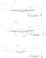
- Figures 4-8 show additional sling embodiments.
- Figures 4 and 5 show slings 50, 60 having substantially the same size and shape as that of Figure 1 , but the end strip portions taper from the intermediate portion to a tip that is the same size as or slightly larger than the diameter of the suture ends.
- the suture 52 is woven through the length of the body 54
- Figure 5 which shows an embodiment of the present invention
- the suture 62 is woven through end strips 64, 66 of the body, but at the suture extends across an external face of the intermediate portion with its loop 68 extending through an opening and protruding from the opposite face.
- the slings 50, 60 are substantially similar to that of Figures 1-3 , but with the differences noted above.
- Figure 6 depicts a sling 70 according to another example.
- the sling 70 is substantially similar to that of Figures 1-5 , but with the differences noted herein.
- the body 72 smoothly tapers to its lateral ends in a manner somewhat like the shape of a teardrop.
- Figure 7 depicts a sling 80 according to yet another example.
- the sling 80 is substantially similar to that of Figures 1-6 , but with the differences noted herein.
- the body has generally a two-piece construction having first and second spaced-apart members 82, 84.
- a first suture 86 is affixed to or formed as part of the first member 82
- a second suture 86 is affixed to or formed as part of the second member 84.
- the first and second members 82, 84 are connected by at least one and preferably two sutures 88, 89.
- the two sutures 88, 89 connecting the first and second members 82, 84 are not bioabsorbable.
- the two sutures 88, 89 connecting the first and second members 82, 84 can be constructed of a bioabsorbable material.
- the first and second members 82, 84 are spaced apart a sufficient distance such that once implanted in a human or animal subject, the first and second members are not placed beneath the urethra of subject, but rather are placed towards the sides (in the periurethral space).
- the first and second members 82, 84 are depicted as generally elongated triangular-like shapes with rounded base portions, any suitably sized and shaped members can be employed.
- Figure 8 depicts a sling 90 according to yet another example.
- the sling 90 is substantially similar to that of Figures 1-7 , but with the differences noted herein.
- the sling includes a sheath 90 (or tubing) that covers and protects the body of the sling during implantation (i.e., passage through a needle body).
- the sheath 92 is the removed in two parts 92a, 92b, thereby exposing the sling body and allowing for final tensioning and positioning.
- a needle delivery device can be used to implant a sling of the present invention in appropriate placement around the urethra while also delivering a sufficient amount of fluid, such as a local anesthetic (e.g., lidocaine).
- a pair of needle delivery devices is used simultaneously and manipulated independently of each other.
- the two needle delivery devices are substantially similar to one another and preferably are mirror images of one another, and thus, only one needle delivery device of the pair will be discussed in detail herein.
- the practitioner would use the appropriate one of the needle delivery devices in his left hand and the other in his right hand.
- the needle delivery device can include a variety of shapes including, arcuate, curved, spiral, helical, or straight.
- the practitioner makes "one pass” with the needle bodies of the needle delivery devices.
- the practitioner advances the needle bodies into the subject's anatomical space while simultaneously delivering both local anesthesia and a sling of the present invention. Accordingly, as the needle bodies are advanced into the anatomical spaces, trauma to surrounding tissue is minimized.
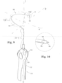
- a needle delivery device 100 includes a needle body 102 having a sharp tip 104 at its distal end and having a lumen 106 extending through the length of the body.
- the tip 104 includes an aperture 108 therethrough that is sized and shape to accommodate a suture end of a sling of the present invention.
- the body 102 is a generally elongated body with an arcuate, curved, or somewhat helical or spiral portion.
- the body 102 is sized and shaped to allow a practitioner to navigate around the pubic ramus for the transobturator approach, or the pubic bone lateral to the symphysis for the retropubic approach.
- the needle body 152 preferably includes three segments: a tip segment 103, a loop segment 105, and a proximal segment 107.
- the tip segment 103 and the loop segment 105 form a continuous curvature loop that spans about 180° in the x-z plane. In alternative embodiments, the curvature of the loop can span about 120° to about 240° in the x-z plane.
- the proximal segment 107 is a generally straight segment extending along the y-axis.
- the tip segment 103 is a generally straight segment extending along the x-axis, which is generally perpendicular to the y-axis.
- the needle body 102 and the tip 104 are fabricated from a biocompatible and rigid material, such as stainless steel, and can be generally smooth and polished on their exterior to facilitate penetration of soft tissue.
- the needle body has a gauge of between 10-25, although other suitable gauges of needle bodies can be employed as well.
- the length of the body 102 is preferably sufficient to reach from the subject's urethra to an insertion site at the skin (typically in either the groin or abdomen). Accordingly, the length of the needle body can be between approximately 3 cm to approximately 20 cm.
- the handle 110 is an ergonomically shaped handle that provides a practitioner the ability to easily manipulate the needle delivery device with his hand.
- the handle 110 has a generally elongated body 112 having a generally bulbous member 114 at its proximal end.
- the bulbous member 114 can include one or more finger grips 116.
- An elongated slot 118 extends from the handle's distal end to the bulbous member 114.
- the assembly 120 includes a receiver 122 for receiving a syringe 124 prefilled with fluid.
- the fluid can include, but is not limited to, a local anesthetic (e.g., lidocaine), another medication, or a saline solution.
- the syringe 124 includes a reservoir of fluid (not shown), a plunger 126 at one end, and a port (not shown) at the other that is in fluid communication with the lumen 106 of the needle body 102.
- the coupling between the syringe's port and the lumen 106 prevents leakage.
- the plunger 126 When depressed, the plunger 126 forces the fluid through the port and into the lumen 106 of the needle body 102.
- a one way valve (not shown) can be located between the syringe's port and the needle's lumen 106 so as to prevent fluid in the needle's lumen from returning to the syringe's reservoir.
- the receiver 122 is mechanically coupled to the body 112 of the handle 110 (such as with fasteners) so as to retain the syringe 124 therein and to hold the port of the syringe in fluid communication with the lumen 106 of the needle body 102.
- the receiver 122 can be sized and shaped to accommodate a suitable syringe.
- the plunger 126 of the syringe 124 somewhat extends beyond the wall of the slot 118 such that the practitioner can manipulate the handle 110 and depress the plunger with a thumb or finger. Accordingly, the practitioner can continuously control how much fluid is injected as he guides the needle body 102 through the anatomical space of the subject.
- the receiver includes a reservoir for housing a sufficient amount of fluid and a plunger for dispensing the fluid through a port of the reservoir. Thus a separate syringe is not used.
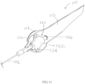
- a needle delivery device 150 includes a generally helical or spiral shaped body 152, which is substantially similar to that shown in Figure 9 .
- the needle body 152 has a sharp tip 154 having a trigger-operated handle 156 to inject a fluid.
- the diameter D of the curved/helical portion of the needle body 152 is approximately between 2 cm and 10 cm.
- the needle body 152 preferably includes three segments: a tip segment 153, a loop segment 155, and a proximal segment 157.
- the tip segment 153 and the loop segment 155 form a continuous curvature loop that spans about 180° in the x-z plane and about 90° in the y-z plane.
- the curvature of the loop can span about 120° to about 240° in the x-z plane.
- the proximal segment 157 is a generally straight segment extending along the y-axis.
- the tip segment 153 is a generally straight segment extending along the x-axis, which is generally perpendicular to the y-axis.
- the needle body 152 and the tip 154 are fabricated from a biocompatible and rigid material, such as stainless steel, and can be generally smooth and polished on their exterior to facilitate penetration of soft tissue. Additionally, as shown in Figure 12 , the body 154 includes a lumen 158 and an aperture 160 at the tip 154.
- FIG. 13 depicts the internal mechanics of the handle 156.
- the handle 156 includes a housing 162 and a dispensing assembly 163.
- the dispensing assembly 163 includes a user-operated trigger 164 extending through the housing and in communication with a fluid chamber or compartment 166.
- the trigger 164 provides the practitioner a way to release a fixed dosage or amount of medication (or other fluid) through the lumen 158 of the needle body 152.
- the trigger 164 is in mechanical communication with the fluid chamber 166.
- the chamber 166 can be constructed of material that flexes or compresses.
- the trigger 164 is mechanically coupled through linkage 168 to a pivotal lever 170 that is locked in place with a toothed ratchet rack 172 (i.e., a generally linear ratchet rack).
- the ratchet rack 172 has a flanged end 174 protruding through the housing 162 of the handle 156 and engaged by the free end of the trigger 164.
- a user-operated button 176 coupled to the lever provides a release for permitting the lever 170 to advance in a backwards (or reverse) direction (so as to expand the chamber)
- the lever 170 compresses the chamber 160 by a fixed amount and the end of the lever advances one tooth of the linear rack 172. In this sense, the end of the lever 170 functions like a pawl. As the chamber 166 is compressed, the fluid therein is forced out through the exit port 178 of the handle 156 and into the lumen 158 of the needle body 102 in a predetermined dosage. Each time the trigger 164 is activated, a predetermined dosage of fluid is released. In an alternative embodiment, the lever forms one wall of the chamber. Thus, as the lever advances, the chamber's volume becomes smaller.
- the fluid chamber can be refilled.
- the practitioner simultaneously presses the button 168 and pulls the flanged end 174 of the ratchet rack 172.
- the dispensing assembly 163 is returned to its initial state where the chamber 166 is fully expanded.
- the practitioner can remove the stopper 180 from an opening of the handle, inject an adequate amount of fluid, and reattach the stopper.
- a one way valve (not shown) can be located adjacent the exit port so as to prevent fluid in the needle's lumen from returning to the fluid chamber.
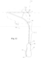
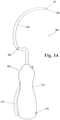
- Figures 14 and 16 depict another example of a needle delivery device 200.
- the needle delivery device has a generally curved body 202 having a sharp tip 204 and a trigger-operated handle 206 to inject a fluid.
- the needle body 202' can be shaped/curved as shown in Figure 15 (such as for use with a retropubic approach).
- the body 204 includes a lumen 208.
- the needle body 202 and tip 204 are constructed from suitable materials of suitable sizes as discussed above.
- FIG 16 depicts the inner mechanics of the handle 206.
- the handle 206 includes a housing 216 and a dispensing assembly 218.
- the dispensing assembly 218 includes a user-operated trigger 220 extending through the housing 216 and in communication with a fluid chamber or compartment 222.
- the fluid chamber 222 includes a piston 224 for dispensing the fluid out through the exit port 226.
- the piston 224 is coupled to mechanical linkage 228 having an end portion 230 extending through the housing 216.
- the end portion 230 is configured to be engaged by the trigger 220.
- activation of the trigger 220 engages the end portion 230 of the mechanical linkage 228 and causes the piston 224 to move into the fluid chamber 222, thereby dispensing a portion of the fluid therein through the exit port 226.
- the fluid chamber 222 is further in fluid communication with a reservoir 232 containing additional fluid.
- the fluid chamber 222 can be coupled to the reservoir 232 with a tube 234.
- a one way valve (not shown) can be attached to the tube 234 so as to prevent fluid from returning to the reservoir 232.
- a second one way valve (not shown) can be located adjacent the exit port 226 so as to prevent fluid in the needle's lumen 208 from returning to the fluid chamber 222.
- the practitioner removes the stopper 236, injects a suitable amount of fluid through the opening in the housing 216, and replaces the stopper.
- the handle 250 comprises a generally ergonomically shaped and substantially rigid housing 252 having an injection port 254 coupled to an exit port 256 near its distal end.
- a syringe 258 of fluid having an associated plunger 260 is coupled to the injection port 254.
- the exit port 256 is coupled to a needle body of the present invention such that the exit port is in fluid communication with the needle's lumen.
- fluid flows from the syringe 258 through the injection port 254, out through the exit port 256, and into the lumen of the needle body.
- the injection port 254 and associated syringe 258 can be located at any suitable place along the housing.
- the handle 270 includes a substantially rigid housing 272 having an opening 274 for exposing a portion of a flexible reservoir 276.
- the handle 270 further includes an exit port 278 in fluid communication with a lumen of a needle body of the present invention. Upon depression of the flexible reservoir 276, fluid is forced out of the exit port 278 and into the lumen of the needle body.
- the reservoir 276 depicted in Figure 18 is a flexible container housed within a rigid housing 272, a first portion of the housing can be substantially rigid while a second portion is substantially compressible.
- the entire handle can be made of a flexible or compressible material such that as the handle is squeezed, fluid is forced out of the export port.
- any of the handles can be combined with any of the needle bodies.
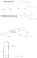
- the needle body 202 can include a small opening 300 in the wall that is sized and shaped to receive a guidewire 302 therethrough, as shown in Figure 19 .
- the opening 300 is located near the handle 206, although the opening can be placed at any suitable location along the body 202. The practitioner can place his finger or thumb over the opening 300 when injecting the fluid so as to prevent the fluid from exiting the opening 300.
- the needle body can include two lumens, one for delivering the anesthesia and the other for delivering the sling.
- the opening in the needle body can include a flap for preventing fluid leakage therethrough.
- the guidewire 302 is constructed of a durable yet flexible material that can be threaded through the needle body.
- the guidewire 302 can be constructed from a plastic or metal wire.
- the guidewire 302 can be placed through the tip 104 of a needle body (such as the needle delivery device 100 of Figure 9 ) into the lumen 106 and out the opening 300. After passage of the guidewire 302, the needle body 102 can be removed and therefore the end of the guidewire can be fastened or otherwise secured to the sling 10 and/or suture 14, using the general principles of the Seldinger Technique.
- the guidewire 302 can include an eyelet 304 at its distal end.
- the eyelet has a size and shape that is suitable to receive a suture end of a sling of the present invention, such as suture end 18.
- the guidewire 302 can be inserted through the opening 300 (or tip end) of the needle body 202, into the lumen 208, and advanced to the needle's tip 204 (or to the opening 300).
- the eyelet 304 collapses, allowing it to be threaded through the needle body more easily.
- the eyelet 304 of the guidewire 304 is inserted through the opening (or tip end) first, although those skilled in the art will understand that the opposite end of the guidewire can be inserted through the opening or tip end.
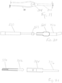
- FIGS 20-24 depict several guidewires according to various examples.
- Each of the guidewires includes an attachment feature for securely grasping a suture end of the sling of the present invention.
- the guidewire 320 includes an anchor 322 at a distal end thereof that can mate with a coopering portion 324 of a suture end 326 of a sling.
- the cooperating portion 324 can include an anchor seat in which the anchor is securely housed.
- Figure 21 depicts a guidewire 330 having an anchor 332 that mates with an anchor seat 334 of a suture end 336 of a sling.
- the anchors are described as being a part of the guidewire, the anchors can be a part of the suture end.
- a suture end 340 of the sling includes a threaded female member 342 attached thereto.
- a guidewire 344 can include a cooperating threaded end 346 that mates with the threaded female member of the suture end.
- a guidewire 350 includes a clamp 352 for securely gripping a suture end 354 of a sling.
- the suture 354 end can be inserted into the clamp 352, and the clamp can be closed (by squeezing the clamping members together).
- the clamp can be closed (by squeezing the clamping members together).
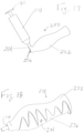
- Figure 25 depicts a finger guard 360 for use with needle delivery devices.
- the finger guard is sized and shaped to cover at least a fingertip (or thumbtip) of the practitioner.
- the finger guard 360 is constructed from a puncture resistant material, such as ballistic nylon, although other suitable materials can be employed as well.
- the practitioner places the finger guard 360 over one his fingers or thumbs.
- the practitioner can feel the placement of the sharp tip of the needle without risking being injured.
- a practitioner uses a pair of needle delivery devices to implant a sling of the present invention in appropriate placement (such as around a subject's urethra) while using the same needle delivery devices to simultaneously deliver a local anesthetic along the insertion tract.
- the following method is described in terms of the sling 10 of Figure 1 and the needle delivery device 100 of Figures 9-11 . However, those skilled in the art will understand that any of the slings and needle delivery devices here described can be employed.
- the practitioner When implanting the sling 10 in a female subject in a first example the practitioner initially applies a local anesthetic and makes a small incision or stab wound in the vaginal area.
- the practitioner threads the first suture end 18 of the sling 10 through the aperture 108 of the first needle delivery device 100 and the second suture end 20 of the sling through the aperture 108 of the second needle delivery device.
- the practitioner inserts the first and needle delivery devices 100, each carrying a portion of the sling 10, through the vaginal incision.
- the practitioner injects the local anesthetic from the handle reservoirs by depressing the plungers 126 as he advances the needles 100 behind the pubic ramus and generally in a direction towards an appropriate area of groin skin or suprapubic region.
- a needle having an aperture at a location other than the tip of the needle such as needle 200
- the practitioner threads a guidewire, such as guidewire 302 into the lumen 208 at the tip 204 of the first needle 200.
- the eyelet 304 of the guidewire 302 is located near the vaginal incision, the practitioner holds the eyelet while removing the needle 200 from the subject's body. The steps of threading the guidewire through the needle and removing the needle from the body are repeated for the second needle.
- the two eyelets 304 of the two guidewires 302 are now located near the vaginal incision.
- the practitioner threads the first suture end 18 of the sling 10 through the eyelet 302 of the first guidewire 304 and the second suture end 20 of the sling through the eyelet of the second guidewire and then pulls the guidewires and hence the sling into placement.
- the practitioner manipulates the proximal ends of the needle delivery devices or guidewires so as to remove the needles or guidewires from the subject through the reverse path.
- the practitioner removes the suture ends from the needles (or guidewires) and positions the intermediate portion 26 of the sling underneath the urethra and positions the adjustment loop 22 accordingly.
- the practitioner adjusts the tension on the sling, cuts the suture ends to about 5 cm long, and secures the suture ends to the subject at a point external to the subject's body.
- the suture ends 18, 20 can be secured beneath suitable bandages, such as TAGADERM TM dressings.
- the practitioner Before closing the incision in the vaginal wall, the practitioner can either superficially bury the loop 22 of the sling 10 in the incision or can close the incision in such a manner that at least a portion of the loop 22 protrudes through the incision for adjusting the tension of the sling 10 after the procedure.
- the practitioner can readjust the sling 10.
- the slings of the present invention can be adjusted up to about seven days or so after the procedure.
- the practitioner can use a urethral dilator to provide counter-traction.
- the practitioner removes the bandages covering the suture ends 18, 20 and manipulates the suture ends and/or loop 22 of the sling 10 (currently located near the site of the vaginal incision). Pulling on the suture loop 22 loosens the sling 10 around the urethra, while pulling on the suture ends 18, 20 tightens the sling around the urethra. Once proper tensioning is established, the practitioner trims suture ends at skin level and cuts the adjustment loop at the midline vaginal incision.
- the subject When implanting the sling 10 in a male subject, the subject is first placed in a high lithotomy position.
- a Foley catheter is placed through the subject's urethra and into his bladder.
- the practitioner applies a local anesthetic such as lidocaine and makes a small incision or midline stab wound in the perineum.
- the practitioner creates subcutaneous spaces with metzenbaum scissors, lateral to the midline urethra on each side.
- the practitioner inserts the first needle body 102 through the perineal incision, and passes the needle body 102 through the obturator foramen, to the appropriate area on the subject's groin.
- the second needle body is passed on the contralateral side, as shown in Figure 26 .
- the practitioner injects the local anesthesia from the handle reservoirs by depressing the plungers 126 as he advances the needles from inside the perineal incision, through the obturator foramen, and out at the ipsilateral groin.
- the practitioner threads the suture ends 18, 20 of the sling 10 through the aperture 108 of each needle body 102; thus, the suture 14 is carried, as anesthetic is simultaneously delivered, along this tract leading up to the groin.
- the suture ends 18, 20 are freed from the needles, and the needles are removed through the perineal incision, leaving only the sling body (e.g., mesh) and suture ready for tensioning.
- the sling body e.g., mesh
- a needle having an aperture at a location other than the tip of the needle such as needle 200
- the practitioner threads a guidewire from outside the groin skin, such as guidewire 302, through the aperture 300 of the first needle.
- the eyelet 304 of the guidewire 302 exits near the incision in the perineal wall, the practitioner holds the eyelet while removing the needle from the subject's body.
- the steps of threading the guidewire through the needle and removing the needle from the body are repeated for the second needle.
- the two eyelets 304 of the two guidewires 302 are now located near the perineal incision.
- the practitioner threads the first suture end 18 of the sling 10 through the eyelet 304 of the first guidewire 302 and the second suture end 20 of the sling through the eyelet of the second guidewire.
- the practitioner manipulates the proximal ends of the needle delivery devices or guidewires so as to remove the needle bodies or guidewires from the subject through the reverse path.
- the practitioner positions the intermediate portion 26 of the sling underneath the urethra and/or the perineal body and positions the adjustment loop 22 accordingly, as generally shown in Figure 27 .
- the practitioner removes the suture ends 18, 20 from the needles (or guidewires) and adjusts the tension and placement of the sling.
- the practitioner can ask the subject to cough (or otherwise engage the subject in an activity that causes intraabdominal pressure) as he is adjusting the tension of the sling 10.
- the practitioner cuts the suture ends 18, 20 to about 5 cm long and secures the suture ends to the subject at a point external to the subject's body.
- the suture ends 18, 20 can be secured beneath suitable bandages, such as TAGADERM TM dressings.
- the practitioner can place a steristrip or suture over the stab wound in the perineal wall such that a portion of the adjustment loop 22 extends through the wound.
- the practitioner can readjust the sling 10, after the patient has assessed its efficacy and voiding function during activities.
- the practitioner removes the bandages covering the suture ends 18, 20 and manipulates the suture ends and/or loop 22 of the sling 10 at the site of the perineal incision. Pulling on the suture loop 22 loosens the sling 10 around the urethra, while pulling on the suture ends 18, 20 tightens the sling around the urethra.
- the practitioner can ask the subject to cough (or otherwise engage the subject in an activity that causes intraabdominal pressure) as he is adjusting the tension of the sling 10. Once proper tensioning is established, the practitioner trims suture ends 18, 20 at skin level and cuts the adjustment loop at the midline vaginal incision.
- the methods can be adapted to provide “outside-in methods" for both female and male subjects.
- the practitioner can insert the first needle body 102 through a female subject's abdomen or groin and the second needle body 102 through the subject's abdomen or groin.
- the practitioner can inject the local anesthetic from the handle reservoirs by depressing the plungers 126 as he advances the needle bodies 102 generally in a direction towards the premade vaginal incision.
- the practitioner can thread the first suture end 18 of the sling 10 through the aperture 108 of the first needle and the second suture end 20 of the sling through the aperture 108 of the second needle.
- the practitioner can manipulate the proximal ends of the needle delivery devices so as to remove the needle bodies the subject through the reverse path. In so doing, the practitioner is simultaneously pulling the suture ends 18, 20 of the sling 10 through the passages initially created by the needles as the needles are removed from the subject's body.
- the present invention provides a kit for the treatment of urinary incontinence according to claim 7.
Landscapes
- Health & Medical Sciences (AREA)
- Life Sciences & Earth Sciences (AREA)
- Surgery (AREA)
- General Health & Medical Sciences (AREA)
- Public Health (AREA)
- Biomedical Technology (AREA)
- Heart & Thoracic Surgery (AREA)
- Veterinary Medicine (AREA)
- Engineering & Computer Science (AREA)
- Animal Behavior & Ethology (AREA)
- Molecular Biology (AREA)
- Nuclear Medicine, Radiotherapy & Molecular Imaging (AREA)
- Medical Informatics (AREA)
- Urology & Nephrology (AREA)
- Anesthesiology (AREA)
- Cardiology (AREA)
- Oral & Maxillofacial Surgery (AREA)
- Transplantation (AREA)
- Vascular Medicine (AREA)
- Hematology (AREA)
- Surgical Instruments (AREA)
- Orthopedics, Nursing, And Contraception (AREA)
Description
- This application claims priority to
U.S. Provisional Patent Application Serial No. 60/952,802, filed July 30, 2008 - The present invention relates generally to the field of medical devices, and in particular to an apparatus for treating stress urinary incontinence in a human or animal subject.
- Stress urinary incontinence ("SUI") is a widespread problem throughout the world affecting people of all ages and gender. SUI is the involuntary leakage of small amounts of urine resulting from an increased pressure in the abdomen and may result while sneezing, coughing, laughing, bending, lifting, etc. While primarily a female problem, men also suffer from stress urinary incontinence, and rates of male SUI are increasing along with the increased use of prostate surgery. Stress incontinence in men is typically the result of a weakened urethral sphincter that surrounds the prostate, frequently as a result of prostate surgery.
- For treating SUI, it is often necessary to resort to surgery. Conventional techniques consist of restoring the natural mechanisms of continence, maintaining the urethra in the abdominal cavity, and/or increasing urethral resistance. To do this, a conventional sling is placed under the urethra, thereby making it possible to improve the suspension and provide some compression of the urethra. Currently, there are a variety of different sling procedures which differ in the anchoring methods and materials used.
- Despite advances in midurethral sling design over the past years, there still remains considerable room for improvements, particularly in sling design and placement. For example, such procedures typically require hospitalization. Thus, many females and males with stress urinary incontinence avoid or delay undergoing an operation. Moreover, although serious complications associated with sling procedures are infrequent, they do occur. In some cases, the slings cause friction in the area of the vagina or urethra during the patient's movements and may injure different organs with which they are in contact. This friction may then cause erosion, inflammation or infection, or even cause rejection of the sling, thereby requiring another operation to surgically remove the sling.
- Other shortcomings of known sling designs include the fact that multiple incisions are typically required to implant a sling, thereby increasing the patient's level of discomfort and recovery time. Additionally, passage of mesh through the skin or subcutaneous tissue can result in patient discomfort and therefore most commonly requires general anesthesia. Moreover, once implanted, the sling cannot be adjusted, and thus if the sling is not implanted in the precise or ideal location, the patient may continue to have incontinence-related issues. There are some devices whose use compromises the surgeon's ability to easily and accurately tension the sling. This is being perceived as a major shortcoming, and is probably a major reason underlying unacceptable initial failure rates of approximately 25%.
- Accordingly, there exists a need for a sling that satisfactorily treats stress urinary incontinence and that permits post-operative adjustment of the sling. Further needs exist for methods for implanting slings that minimize a subject's discomfort and recovery time and allow for placement under local anesthesia.
- Document
US 2002/0107430 A1 discloses an apparatus for the treatment of stress urinary incontinence including a sling body having a constant width and a suture extending through the sling body. - Document
US 2003/0065402 A1 discloses a similar implantable article. Further reference is made to documentUS 2006/0009673 A1 . - Documents
US 2006/0195007 A1 andUS 2007/0068538 A1 are related to implants for use in treating urogenital conditions. - Advantageously, the present invention provides an adjustable sling (or a 'mini sling' having minimal mesh arms traveling though hidden anatomic spaces) for treating stress urinary incontinence in both female and male subjects. Notably, a practitioner can implant the sling in an office or other ambulatory setting using a local anesthetic rather than using general anesthesia in a hospital setting. Such implantation can be achieved, in the female, by passing the needle from a vaginal incision out to either the groin area ("inside out transobturator" approach), or suprapubic region ("inside-out retropubic" approach). In the male, such implantation can be achieved by passing the needle from a perineal incision out to the groin area ("inside-out transobturator approach"), which before now has not been described or performed in male subjects. Also advantageously, the sling of the present invention can be adjusted both during the procedure and at a future a date without further surgery, incisions, or puncture wounds. Since the subject is awake (and not under general anesthesia), the tension of the sling can be adjusted while the patient coughs (or engaged in another activity that causes intraabdominal pressure). Additionally, if the sling is not performing optimally, the practitioner can adjust the tension days after the procedure.
- In a first form, the present invention provides an apparatus according to
claim 1 for the treatment of stress urinary incontinence. The apparatus includes a sling body having an intermediate portion and two end portions and a suture, wherein the suture extends through the sling body. The suture further provides an adjustment loop proximate to the intermediate portion for postoperative adjustment. The sling is body is sized and shaped so at to minimize excess body from spanning through anatomical spaces where it not needed for the treatment of incontinence. - It is also described a needle delivery device for implanting a medical device for the treatment of stress urinary incontinence. The needle delivery device has a needle body, wherein the needle body includes an aperture configured to receive a suture end of the medical device, and a lumen extending through the length of the needle body, wherein the lumen is adapted to deliver a fluid therethrough. Accordingly, in use, the needle delivery device can simultaneously deliver a local anesthesia while implanting the medical device through a precise anatomic pass with the needle body.
- A method for implanting a medical device to treat urinary incontinence in a human or animal subject is also described. The method includes the steps of making an incision in the vaginal or perineal area; inserting first and second needles into the human or animal subject; guiding the needles to the appropriate area in the groin or suprapubic area while simultaneously injecting a local anesthetic with the needles; removing the needles; positioning the sling; and leaving at least a portion of the sling (such as the tensioning suture) accessible for post-operative adjustment of the sling.
- In another form, the present invention provides a kit for the treatment of urinary incontinence. The kit includes an apparatus according to any of claims 1-6, a pair of needle delivery devices, wherein each needle delivery device is configured to simultaneously deliver local anesthesia and implant the sling around the urethra, and a finger guard.
- These and other aspects, features and advantages of the invention will be understood with reference to the drawing figures and detailed description herein, and will be realized by means of the various elements and combinations particularly pointed out in the appended claims. It is to be understood that both the foregoing general description and the following brief description of the drawings and detailed description of the invention are exemplary and explanatory of preferred embodiments of the invention, and are not restrictive of the invention, as claimed.
-
-
Figure 1 depicts a front view of a sling in accordance with a first example. -
Figure 2 depicts a front view of an end portion of the sling ofFigure 1 . -
Figure 3 depicts a front view of a modified end portion of the sling ofFigure 1 . -
Figure 4 depicts a perspective view of a sling in accordance with a second exampl. -
Figure 5 depicts a perspective view of a sling in accordance with an embodiment of the present invention. -
Figure 6 depicts a perspective view of a sling in accordance with another example. -
Figure 7 depicts a front view of a sling in accordance with a further example. -
Figure 8 depicts a perspective view of a sling in accordance with another example. -
Figure 9 depicts a perspective view of a needle delivery device for delivering a sling according to an example. -
Figure 10 depicts a detailed view of the tip of the needle delivery device ofFigure 9 . -
Figure 11 depicts a perspective view of the handle of the needle delivery device ofFigure 9 and shown with a portion of its housing removed. -
Figure 12 depicts a perspective view of a needle delivery device for delivering a sling according to another example. -
Figure 13 depicts a sectional view of the handle of the needle delivery device ofFigure 12 . -
Figure 14 depicts a perspective view of a needle delivery device for delivering a sling according to another example. -
Figure 15 depicts a perspective view of a needle body for delivering a sling according to another example. -
Figure 16 depicts a sectional view of the handle of the needle delivery device ofFigure 14 . -
Figure 17 depicts a perspective view of a handle for a needle delivery device of the present invention according to another example. -
Figure 18 depicts a perspective view of a handle for a needle delivery device according to yet another example. -
Figure 19 depicts a perspective view of a portion of a guidewire for use with a needle and shown receiving a suture end of a sling of the present invention. -
Figure 20 depicts a side view of a guidewire and suture end of a sling according to another example. -
Figure 21 depicts a side view of a guidewire and suture end of a sling according to yet another example. -
Figures 22 and 23 depict perspective views of a guidewire and suture end of a sling according to another example. -
Figure 24 depicts a perspective view of a guidewire and suture end of a sling according to yet another example. -
Figure 25 depicts a finger guard according to an example for use with a needle. -
Figures 26-27 depict pictorial representations of a pair of needle delivery devices used to implant a sling of the present invention in a male subject. - The present invention may be understood more readily by reference to the following detailed description of the invention taken in connection with the accompanying drawing figures, which form part of this disclosure. It is also understood that this invention is not limited to the specific devices, described and/or shown herein, and that the terminology used herein is for the purpose of describing particular embodiments by way of example only and is not intended to be limiting of the claimed invention.
- The present invention provides a sling for treating incontinence and a kit for delivering the sling around a subject's urethra while at the same time delivering local anesthesia along the tissue tract through which the sling is delivered.
- As shown in
Figure 1 , thesling 10 includes a flexible body 12 having asingle suture 14 extending or woven through the body generally along the sling'slongitudinal axis 16. Thesuture 14 can be affixed to or formed as part of the body 12. The suture includes ends 18, 20 extending from lateral sides of the body 12 and anintermediate loop portion 22. The ends 16, 18 are configured to secure thesling 10 in the subject as well as to adjust the tension of the sling. Theloop 22 also is configured to aid the practitioner in adjusting the tension of thesling 10 when it is implanted and postoperatively. Although a single suture is discussed herein, a plurality of sutures can be used. In such instances, the sutures can extend from a point near the lateral edges of the body or multiple sutures can extend through the length of the body. Preferably, thesuture 14 is constructed of a bioabsorbable material such as but not limited to PGA, PDS, PLGA, VICRYL™, and catgut. A bioabsorbable suture absorbs in the subject's body and avoids an additional visit to the practitioner to remove the sutures. Alternatively, thesuture 92 can be constructed of a non-absorbable biocompatible material and removed at a future date (or not removed at all). - Preferably, the body 12 of the
sling 10 is symmetrically shaped about both itslongitudinal axis 16 and its transverse axis 24. As shown, the body 12 has an intermediate orsuburethral portion 26 and two end (or periurethral)portions intermediate potion 26 has a generally elongated hexagonal like shape (i.e., elongated along the longitudinal axis 16), while theend portions suture 14. In alternative embodiments, the size and shape of the sling can vary. For example, the intermediate portion can have a tapered oval shape (i.e., tapered in the direction along the longitudinal axis). Additionally, it may be advantageous to implant a longer sling in a male subject and shorter sling in a female subject. However generally, the widths are approximately the same regardless of whether the sling is implanted in a male or female subject. For example, the width W1 of the intermediate portion can be approximately 10 mm to 40 mm. The widths W2 of the end strips can be approximately 5 mm to 10 mm. Advantageously, this construction minimizes the amount of the sling body that is located in the anatomical spaces of the subject. For a sling to be implanted in a female subject, the length of the body can be between approximately 3 cm to 13 cm, and preferably around 8 cm, with the intermediate portion approximately 3-5 cm long. For a sling to be implanted in a male subject, the length of the body can be between approximately 12 cm to 22 cm, and preferably around 16 cm with the intermediate portion approximately 8-12 cm long. As shown, the end strips taper at their lateral ends to a few millimeters, such as between about 3 mm to 30 mm, and more preferably around 5 mm. - The body 12 is preferably constructed from a sheet-like material. Preferably, the sheet-like material comprises a biocompatible, surgical mesh material such as polypropylene, that does not absorb in the subject's body. Other exemplary biocompatible mesh materials include nylon, polyester, and polytetrafluoroethylene. In such embodiments utilizing mesh, the
sling 10 is held in appropriate placement in the subject's body by the friction between the sling and the surrounding tissue. The subject's body forms scar tissue around and through the mesh body, thereby further securely holding the mesh body in place. However, other suitable biocompatible materials, including "non-mesh" materials can be used as well. Alternatively, bioabsorbable materials such as polyglycolic acid, polylactic acid, PEA, PEUR, PEG, and PLLA can be employed. - Advantageously, when implanted in a human or animal subject, the sling body preferably does not extend through the subject's skin. Rather, only the suture ends (which eventually absorb into the body) temporarily extend through the patient's skin to thereby allow retensioning at a future date. Accordingly, since the overall size of the sling body is reduced and therefore does not extend into anatomical spaces where it provides no additional benefits for the treatment of incontinence, patient discomfort is significantly reduced.
- Optionally, the sling body 12 can be constructed of a single size and shape that can be trimmed to an appropriate size and shape. The
sling body 10 has one ormore sutures 14 secured at multiple points along the body 12 of the sling. For example, thesuture 14 can be attached to the body 12 of the sling 10 (e.g., mesh sling) withmultiple knots 32. The plurality ofknots 32 securing thesuture 14 to the body 12 prevents the suture from detaching from the sling body when the body is cut. For example,Figures 1 and 2 depict end strips 28 of thesling 10 having threesuch knots 32. Accordingly, the practitioner can cut the sling body 12, such as in the areas oflines 34 or 36, thereby removing segments of the mesh body, to an appropriate size without detaching thesuture 14 from thesling 10, so as to achieve the size shown inFigure 3 . Thesuture 14 can be tied (or otherwise secured) to the sling body with any suitable number of knots. Thus, the practitioner can cut the sling body to any suitable size and shape without disengaging the suture from the body. -
Figures 4-8 show additional sling embodiments. For example,Figures 4 and 5 show slings 50, 60 having substantially the same size and shape as that ofFigure 1 , but the end strip portions taper from the intermediate portion to a tip that is the same size as or slightly larger than the diameter of the suture ends. The notable difference betweenFigures 4 and 5 is that inFigure 4 , thesuture 52 is woven through the length of the body 54, while inFigure 5 , which shows an embodiment of the present invention, thesuture 62 is woven through end strips 64, 66 of the body, but at the suture extends across an external face of the intermediate portion with its loop 68 extending through an opening and protruding from the opposite face. Otherwise, theslings 50, 60 are substantially similar to that ofFigures 1-3 , but with the differences noted above. -
Figure 6 depicts a sling 70 according to another example. The sling 70 is substantially similar to that ofFigures 1-5 , but with the differences noted herein. In this embodiment, thebody 72 smoothly tapers to its lateral ends in a manner somewhat like the shape of a teardrop. -
Figure 7 depicts a sling 80 according to yet another example. The sling 80 is substantially similar to that ofFigures 1-6 , but with the differences noted herein. The body has generally a two-piece construction having first and second spaced-apartmembers first suture 86 is affixed to or formed as part of thefirst member 82, and asecond suture 86 is affixed to or formed as part of thesecond member 84. The first andsecond members sutures 88, 89. Preferably, the twosutures 88, 89 connecting the first andsecond members sutures 88, 89 connecting the first andsecond members second members second members -
Figure 8 depicts asling 90 according to yet another example. Thesling 90 is substantially similar to that ofFigures 1-7 , but with the differences noted herein. The sling includes a sheath 90 (or tubing) that covers and protects the body of the sling during implantation (i.e., passage through a needle body). Thesheath 92 is the removed in two parts 92a, 92b, thereby exposing the sling body and allowing for final tensioning and positioning. - As shown in
Figures 9-18 , a needle delivery device can be used to implant a sling of the present invention in appropriate placement around the urethra while also delivering a sufficient amount of fluid, such as a local anesthetic (e.g., lidocaine). Preferably, a pair of needle delivery devices is used simultaneously and manipulated independently of each other. The two needle delivery devices are substantially similar to one another and preferably are mirror images of one another, and thus, only one needle delivery device of the pair will be discussed in detail herein. Thus, the practitioner would use the appropriate one of the needle delivery devices in his left hand and the other in his right hand. As discussed below, the needle delivery device can include a variety of shapes including, arcuate, curved, spiral, helical, or straight. - Advantageously, the practitioner makes "one pass" with the needle bodies of the needle delivery devices. In other words, the practitioner advances the needle bodies into the subject's anatomical space while simultaneously delivering both local anesthesia and a sling of the present invention. Accordingly, as the needle bodies are advanced into the anatomical spaces, trauma to surrounding tissue is minimized.
- In a first example depicted in
Figures 9-11 , aneedle delivery device 100 includes aneedle body 102 having asharp tip 104 at its distal end and having alumen 106 extending through the length of the body. Thetip 104 includes anaperture 108 therethrough that is sized and shape to accommodate a suture end of a sling of the present invention. As depicted, thebody 102 is a generally elongated body with an arcuate, curved, or somewhat helical or spiral portion. Preferably, thebody 102 is sized and shaped to allow a practitioner to navigate around the pubic ramus for the transobturator approach, or the pubic bone lateral to the symphysis for the retropubic approach. - The
needle body 152 preferably includes three segments: atip segment 103, aloop segment 105, and aproximal segment 107. Preferably, thetip segment 103 and theloop segment 105 form a continuous curvature loop that spans about 180° in the x-z plane. In alternative embodiments, the curvature of the loop can span about 120° to about 240° in the x-z plane. Preferably, theproximal segment 107 is a generally straight segment extending along the y-axis. Also preferably, thetip segment 103 is a generally straight segment extending along the x-axis, which is generally perpendicular to the y-axis. - Preferably, the
needle body 102 and thetip 104 are fabricated from a biocompatible and rigid material, such as stainless steel, and can be generally smooth and polished on their exterior to facilitate penetration of soft tissue. In an example, the needle body has a gauge of between 10-25, although other suitable gauges of needle bodies can be employed as well. The length of thebody 102 is preferably sufficient to reach from the subject's urethra to an insertion site at the skin (typically in either the groin or abdomen). Accordingly, the length of the needle body can be between approximately 3 cm to approximately 20 cm. - At the proximal end of the
needle body 102 is ahandle 110. Preferably, thehandle 110 is an ergonomically shaped handle that provides a practitioner the ability to easily manipulate the needle delivery device with his hand. As shown inFigures 9 and11 , thehandle 110 has a generallyelongated body 112 having a generallybulbous member 114 at its proximal end. Thebulbous member 114 can include one or more finger grips 116. Anelongated slot 118 extends from the handle's distal end to thebulbous member 114. - Within the
bulbous member 114, as shown more clearly inFigure 11 , is anassembly 120 for injecting a fluid through theneedle body 102. Theassembly 120 includes areceiver 122 for receiving asyringe 124 prefilled with fluid. The fluid can include, but is not limited to, a local anesthetic (e.g., lidocaine), another medication, or a saline solution. Thesyringe 124 includes a reservoir of fluid (not shown), aplunger 126 at one end, and a port (not shown) at the other that is in fluid communication with thelumen 106 of theneedle body 102. Preferably, the coupling between the syringe's port and thelumen 106 prevents leakage. When depressed, theplunger 126 forces the fluid through the port and into thelumen 106 of theneedle body 102. Optionally, a one way valve (not shown) can be located between the syringe's port and the needle'slumen 106 so as to prevent fluid in the needle's lumen from returning to the syringe's reservoir. Thereceiver 122 is mechanically coupled to thebody 112 of the handle 110 (such as with fasteners) so as to retain thesyringe 124 therein and to hold the port of the syringe in fluid communication with thelumen 106 of theneedle body 102. Those skilled in the art will understand that thereceiver 122 can be sized and shaped to accommodate a suitable syringe. - As shown, the
plunger 126 of thesyringe 124 somewhat extends beyond the wall of theslot 118 such that the practitioner can manipulate thehandle 110 and depress the plunger with a thumb or finger. Accordingly, the practitioner can continuously control how much fluid is injected as he guides theneedle body 102 through the anatomical space of the subject. In an alternative, the receiver includes a reservoir for housing a sufficient amount of fluid and a plunger for dispensing the fluid through a port of the reservoir. Thus a separate syringe is not used. - In another example as depicted in
Figures 12-13 , aneedle delivery device 150 includes a generally helical or spiral shapedbody 152, which is substantially similar to that shown inFigure 9 . Theneedle body 152 has a sharp tip 154 having a trigger-operatedhandle 156 to inject a fluid. Preferably, the diameter D of the curved/helical portion of theneedle body 152 is approximately between 2 cm and 10 cm. Theneedle body 152 preferably includes three segments: atip segment 153, a loop segment 155, and aproximal segment 157. Preferably, thetip segment 153 and the loop segment 155 form a continuous curvature loop that spans about 180° in the x-z plane and about 90° in the y-z plane. In alternative embodiments, the curvature of the loop can span about 120° to about 240° in the x-z plane. Preferably, theproximal segment 157 is a generally straight segment extending along the y-axis. Also preferably, thetip segment 153 is a generally straight segment extending along the x-axis, which is generally perpendicular to the y-axis. - Additionally, the
needle body 152 and the tip 154 are fabricated from a biocompatible and rigid material, such as stainless steel, and can be generally smooth and polished on their exterior to facilitate penetration of soft tissue. Additionally, as shown inFigure 12 , the body 154 includes alumen 158 and an aperture 160 at the tip 154. -
Figure 13 depicts the internal mechanics of thehandle 156. Thehandle 156 includes ahousing 162 and a dispensingassembly 163. The dispensingassembly 163 includes a user-operatedtrigger 164 extending through the housing and in communication with a fluid chamber or compartment 166. Thetrigger 164 provides the practitioner a way to release a fixed dosage or amount of medication (or other fluid) through thelumen 158 of theneedle body 152. Thetrigger 164 is in mechanical communication with the fluid chamber 166. Preferably, the chamber 166 can be constructed of material that flexes or compresses. Thetrigger 164 is mechanically coupled throughlinkage 168 to apivotal lever 170 that is locked in place with a toothed ratchet rack 172 (i.e., a generally linear ratchet rack). Theratchet rack 172 has aflanged end 174 protruding through thehousing 162 of thehandle 156 and engaged by the free end of thetrigger 164. A user-operatedbutton 176 coupled to the lever provides a release for permitting thelever 170 to advance in a backwards (or reverse) direction (so as to expand the chamber) - Thus, when the
trigger 164 is activated, thelever 170 compresses the chamber 160 by a fixed amount and the end of the lever advances one tooth of thelinear rack 172. In this sense, the end of thelever 170 functions like a pawl. As the chamber 166 is compressed, the fluid therein is forced out through the exit port 178 of thehandle 156 and into thelumen 158 of theneedle body 102 in a predetermined dosage. Each time thetrigger 164 is activated, a predetermined dosage of fluid is released. In an alternative embodiment, the lever forms one wall of the chamber. Thus, as the lever advances, the chamber's volume becomes smaller. - In the depicted example of
Figures 12 and13 , the fluid chamber can be refilled. Preferably, the practitioner simultaneously presses thebutton 168 and pulls theflanged end 174 of theratchet rack 172. In so doing, the dispensingassembly 163 is returned to its initial state where the chamber 166 is fully expanded. The practitioner can remove thestopper 180 from an opening of the handle, inject an adequate amount of fluid, and reattach the stopper. Optionally, a one way valve (not shown) can be located adjacent the exit port so as to prevent fluid in the needle's lumen from returning to the fluid chamber. -
Figures 14 and16 depict another example of aneedle delivery device 200. The needle delivery device has a generallycurved body 202 having asharp tip 204 and a trigger-operatedhandle 206 to inject a fluid. Alternatively, the needle body 202' can be shaped/curved as shown inFigure 15 (such as for use with a retropubic approach). Additionally, as shown inFigure 14 , thebody 204 includes alumen 208. Theneedle body 202 andtip 204 are constructed from suitable materials of suitable sizes as discussed above. -
Figure 16 depicts the inner mechanics of thehandle 206. Thehandle 206 includes ahousing 216 and a dispensingassembly 218. The dispensingassembly 218 includes a user-operatedtrigger 220 extending through thehousing 216 and in communication with a fluid chamber orcompartment 222. Thefluid chamber 222 includes apiston 224 for dispensing the fluid out through theexit port 226. Thepiston 224 is coupled tomechanical linkage 228 having anend portion 230 extending through thehousing 216. Theend portion 230 is configured to be engaged by thetrigger 220. Thus, activation of thetrigger 220 engages theend portion 230 of themechanical linkage 228 and causes thepiston 224 to move into thefluid chamber 222, thereby dispensing a portion of the fluid therein through theexit port 226. - The
fluid chamber 222 is further in fluid communication with areservoir 232 containing additional fluid. Thefluid chamber 222 can be coupled to thereservoir 232 with atube 234. A one way valve (not shown) can be attached to thetube 234 so as to prevent fluid from returning to thereservoir 232. A second one way valve (not shown) can be located adjacent theexit port 226 so as to prevent fluid in the needle'slumen 208 from returning to thefluid chamber 222. To refill thereservoir 232, the practitioner removes thestopper 236, injects a suitable amount of fluid through the opening in thehousing 216, and replaces the stopper. - Another example of a
handle 250 is shown inFigure 17 . Thehandle 250 comprises a generally ergonomically shaped and substantially rigid housing 252 having aninjection port 254 coupled to anexit port 256 near its distal end. Asyringe 258 of fluid having an associatedplunger 260 is coupled to theinjection port 254. Theexit port 256 is coupled to a needle body of the present invention such that the exit port is in fluid communication with the needle's lumen. Upon depression of theplunger 260, fluid flows from thesyringe 258 through theinjection port 254, out through theexit port 256, and into the lumen of the needle body. Theinjection port 254 and associatedsyringe 258 can be located at any suitable place along the housing. - Another example embodiment of a handle 270 is shown in
Figure 18 . The handle 270 includes a substantiallyrigid housing 272 having anopening 274 for exposing a portion of aflexible reservoir 276. The handle 270 further includes anexit port 278 in fluid communication with a lumen of a needle body of the present invention. Upon depression of theflexible reservoir 276, fluid is forced out of theexit port 278 and into the lumen of the needle body. Although thereservoir 276 depicted inFigure 18 is a flexible container housed within arigid housing 272, a first portion of the housing can be substantially rigid while a second portion is substantially compressible. Still alternatively, the entire handle can be made of a flexible or compressible material such that as the handle is squeezed, fluid is forced out of the export port. - Any of the handles can be combined with any of the needle bodies.
- Referring back to
Figure 14 , theneedle body 202 can include asmall opening 300 in the wall that is sized and shaped to receive aguidewire 302 therethrough, as shown inFigure 19 . Preferably, theopening 300 is located near thehandle 206, although the opening can be placed at any suitable location along thebody 202. The practitioner can place his finger or thumb over theopening 300 when injecting the fluid so as to prevent the fluid from exiting theopening 300. Alternatively, the needle body can include two lumens, one for delivering the anesthesia and the other for delivering the sling. Alternatively or additionally, the opening in the needle body can include a flap for preventing fluid leakage therethrough. - Preferably, the
guidewire 302 is constructed of a durable yet flexible material that can be threaded through the needle body. For example, theguidewire 302 can be constructed from a plastic or metal wire. In addition, theguidewire 302 can be placed through thetip 104 of a needle body (such as theneedle delivery device 100 ofFigure 9 ) into thelumen 106 and out theopening 300. After passage of theguidewire 302, theneedle body 102 can be removed and therefore the end of the guidewire can be fastened or otherwise secured to thesling 10 and/orsuture 14, using the general principles of the Seldinger Technique. - As depicted in
Figure 19 , theguidewire 302 can include aneyelet 304 at its distal end. Preferably, the eyelet has a size and shape that is suitable to receive a suture end of a sling of the present invention, such assuture end 18. Accordingly, theguidewire 302 can be inserted through the opening 300 (or tip end) of theneedle body 202, into thelumen 208, and advanced to the needle's tip 204 (or to the opening 300). As theguidewire 302 is inserted intoneedle body 202, theeyelet 304 collapses, allowing it to be threaded through the needle body more easily. Preferably, theeyelet 304 of theguidewire 304 is inserted through the opening (or tip end) first, although those skilled in the art will understand that the opposite end of the guidewire can be inserted through the opening or tip end. -
Figures 20-24 depict several guidewires according to various examples. Each of the guidewires includes an attachment feature for securely grasping a suture end of the sling of the present invention. For example inFigure 20 , theguidewire 320 includes ananchor 322 at a distal end thereof that can mate with acoopering portion 324 of asuture end 326 of a sling. As shown inFigure 20 , the cooperatingportion 324 can include an anchor seat in which the anchor is securely housed. Once theguidewire 320 andsuture end 326 are pulled through a needle body of the present invention and the sling is at least somewhat around the urethra or in an otherwise appropriate placement, the practitioner can disengage the guidewire from the suture end by pulling the two apart.Figure 21 depicts aguidewire 330 having ananchor 332 that mates with ananchor seat 334 of asuture end 336 of a sling. Although the anchors are described as being a part of the guidewire, the anchors can be a part of the suture end. - In
Figures 22 and 23 , asuture end 340 of the sling includes a threadedfemale member 342 attached thereto. Aguidewire 344 can include a cooperating threadedend 346 that mates with the threaded female member of the suture end. Once theguidewire 344 andsuture end 340 are pulled through a needle body and the sling is at least somewhat around the urethra or otherwise in appropriate placement, the practitioner can cut the suture end to remove the threaded female member or can otherwise disengage the threaded female member from the suture end. Although the threaded female member is described as being a part of the suture end, the threaded female member can be a part of the guidewire. - In
Figure 24 , aguidewire 350 includes aclamp 352 for securely gripping asuture end 354 of a sling. Thesuture 354 end can be inserted into theclamp 352, and the clamp can be closed (by squeezing the clamping members together). Once theguidewire 350 andsuture end 354 are pulled through a needle body and the sling is at least somewhat around the urethra (or otherwise placed in an appropriate placement), the practitioner can disengage thesuture end 354 from theguidewire 350 by opening theclamp 352 and releasing the suture end. Although the clamp is described as being a part of the guidewire, the clamp can be a part of the suture end. -
Figure 25 depicts afinger guard 360 for use with needle delivery devices. The finger guard is sized and shaped to cover at least a fingertip (or thumbtip) of the practitioner. Preferably, thefinger guard 360 is constructed from a puncture resistant material, such as ballistic nylon, although other suitable materials can be employed as well. In use, the practitioner places thefinger guard 360 over one his fingers or thumbs. Thus, as the practitioner is guiding a needle body from a point external to the subject's body to an area of a premade incision, the practitioner can feel the placement of the sharp tip of the needle without risking being injured. - In use, a practitioner uses a pair of needle delivery devices to implant a sling of the present invention in appropriate placement (such as around a subject's urethra) while using the same needle delivery devices to simultaneously deliver a local anesthetic along the insertion tract. The following method is described in terms of the
sling 10 ofFigure 1 and theneedle delivery device 100 ofFigures 9-11 . However, those skilled in the art will understand that any of the slings and needle delivery devices here described can be employed. - When implanting the
sling 10 in a female subject in a first example the practitioner initially applies a local anesthetic and makes a small incision or stab wound in the vaginal area. The practitioner threads thefirst suture end 18 of thesling 10 through theaperture 108 of the firstneedle delivery device 100 and thesecond suture end 20 of the sling through theaperture 108 of the second needle delivery device. The practitioner inserts the first andneedle delivery devices 100, each carrying a portion of thesling 10, through the vaginal incision. The practitioner injects the local anesthetic from the handle reservoirs by depressing theplungers 126 as he advances theneedles 100 behind the pubic ramus and generally in a direction towards an appropriate area of groin skin or suprapubic region. - Alternatively if a needle is used having an aperture at a location other than the tip of the needle such as
needle 200, once thetips 208 of the needles protrude through the skin in the groin or suprapubic region, the practitioner threads a guidewire, such asguidewire 302 into thelumen 208 at thetip 204 of thefirst needle 200. When theeyelet 304 of theguidewire 302 is located near the vaginal incision, the practitioner holds the eyelet while removing theneedle 200 from the subject's body. The steps of threading the guidewire through the needle and removing the needle from the body are repeated for the second needle. Thus, the twoeyelets 304 of the twoguidewires 302 are now located near the vaginal incision. The practitioner threads thefirst suture end 18 of thesling 10 through theeyelet 302 of thefirst guidewire 304 and thesecond suture end 20 of the sling through the eyelet of the second guidewire and then pulls the guidewires and hence the sling into placement. - Regardless of whether the practitioner uses the needles or guidewires to pull the sling, the practitioner manipulates the proximal ends of the needle delivery devices or guidewires so as to remove the needles or guidewires from the subject through the reverse path. Once the needles (or guidewires) exit the body, the practitioner removes the suture ends from the needles (or guidewires) and positions the
intermediate portion 26 of the sling underneath the urethra and positions theadjustment loop 22 accordingly. The practitioner adjusts the tension on the sling, cuts the suture ends to about 5 cm long, and secures the suture ends to the subject at a point external to the subject's body. For example, the suture ends 18, 20 can be secured beneath suitable bandages, such as TAGADERM™ dressings. Before closing the incision in the vaginal wall, the practitioner can either superficially bury theloop 22 of thesling 10 in the incision or can close the incision in such a manner that at least a portion of theloop 22 protrudes through the incision for adjusting the tension of thesling 10 after the procedure. - Within about 24-48 hours after the procedure, the practitioner can readjust the
sling 10. The slings of the present invention can be adjusted up to about seven days or so after the procedure. Optionally, the practitioner can use a urethral dilator to provide counter-traction. The practitioner removes the bandages covering the suture ends 18, 20 and manipulates the suture ends and/orloop 22 of the sling 10 (currently located near the site of the vaginal incision). Pulling on thesuture loop 22 loosens thesling 10 around the urethra, while pulling on the suture ends 18, 20 tightens the sling around the urethra. Once proper tensioning is established, the practitioner trims suture ends at skin level and cuts the adjustment loop at the midline vaginal incision. - When implanting the
sling 10 in a male subject, the subject is first placed in a high lithotomy position. A Foley catheter is placed through the subject's urethra and into his bladder. The practitioner applies a local anesthetic such as lidocaine and makes a small incision or midline stab wound in the perineum. The practitioner creates subcutaneous spaces with metzenbaum scissors, lateral to the midline urethra on each side. The practitioner inserts thefirst needle body 102 through the perineal incision, and passes theneedle body 102 through the obturator foramen, to the appropriate area on the subject's groin. The second needle body is passed on the contralateral side, as shown inFigure 26 . The practitioner injects the local anesthesia from the handle reservoirs by depressing theplungers 126 as he advances the needles from inside the perineal incision, through the obturator foramen, and out at the ipsilateral groin. Prior to passage of each needle, the practitioner threads the suture ends 18, 20 of thesling 10 through theaperture 108 of eachneedle body 102; thus, thesuture 14 is carried, as anesthetic is simultaneously delivered, along this tract leading up to the groin. Once thetips 104 of theneedles 100 protrude through the groin skin, the suture ends 18, 20 are freed from the needles, and the needles are removed through the perineal incision, leaving only the sling body (e.g., mesh) and suture ready for tensioning. - Alternatively, if a needle is used having an aperture at a location other than the tip of the needle such as
needle 200, once thetips 204 of theneedles 200 protrude through the groin skin, the practitioner threads a guidewire from outside the groin skin, such asguidewire 302, through theaperture 300 of the first needle. When theeyelet 304 of theguidewire 302 exits near the incision in the perineal wall, the practitioner holds the eyelet while removing the needle from the subject's body. The steps of threading the guidewire through the needle and removing the needle from the body are repeated for the second needle. Thus, the twoeyelets 304 of the twoguidewires 302 are now located near the perineal incision. The practitioner threads thefirst suture end 18 of thesling 10 through theeyelet 304 of thefirst guidewire 302 and thesecond suture end 20 of the sling through the eyelet of the second guidewire. - Regardless of whether the practitioner uses the needles or guidewires to pull the sling, the practitioner manipulates the proximal ends of the needle delivery devices or guidewires so as to remove the needle bodies or guidewires from the subject through the reverse path. The practitioner positions the
intermediate portion 26 of the sling underneath the urethra and/or the perineal body and positions theadjustment loop 22 accordingly, as generally shown inFigure 27 . Once the needles (or guidewires) exit the subject's body, the practitioner removes the suture ends 18, 20 from the needles (or guidewires) and adjusts the tension and placement of the sling. For example, the practitioner can ask the subject to cough (or otherwise engage the subject in an activity that causes intraabdominal pressure) as he is adjusting the tension of thesling 10. The practitioner cuts the suture ends 18, 20 to about 5 cm long and secures the suture ends to the subject at a point external to the subject's body. For example, the suture ends 18, 20 can be secured beneath suitable bandages, such as TAGADERM™ dressings. The practitioner can place a steristrip or suture over the stab wound in the perineal wall such that a portion of theadjustment loop 22 extends through the wound. - Within about 24-48 hours or up to a week or so after the procedure, the practitioner can readjust the
sling 10, after the patient has assessed its efficacy and voiding function during activities. The practitioner removes the bandages covering the suture ends 18, 20 and manipulates the suture ends and/orloop 22 of thesling 10 at the site of the perineal incision. Pulling on thesuture loop 22 loosens thesling 10 around the urethra, while pulling on the suture ends 18, 20 tightens the sling around the urethra. To aid in the adjustment of the tensioning, the practitioner can ask the subject to cough (or otherwise engage the subject in an activity that causes intraabdominal pressure) as he is adjusting the tension of thesling 10. Once proper tensioning is established, the practitioner trims suture ends 18, 20 at skin level and cuts the adjustment loop at the midline vaginal incision. - Although the present disclosure is described in terms of "inside-out" methods of implanting slings in female and male subjects, the methods can be adapted to provide "outside-in methods" for both female and male subjects. For example, the practitioner can insert the
first needle body 102 through a female subject's abdomen or groin and thesecond needle body 102 through the subject's abdomen or groin. The practitioner can inject the local anesthetic from the handle reservoirs by depressing theplungers 126 as he advances theneedle bodies 102 generally in a direction towards the premade vaginal incision. Once thetips 104 of the needles protrude through the vaginal incision, the practitioner can thread thefirst suture end 18 of thesling 10 through theaperture 108 of the first needle and thesecond suture end 20 of the sling through theaperture 108 of the second needle. The practitioner can manipulate the proximal ends of the needle delivery devices so as to remove the needle bodies the subject through the reverse path. In so doing, the practitioner is simultaneously pulling the suture ends 18, 20 of thesling 10 through the passages initially created by the needles as the needles are removed from the subject's body. - Additionally, other suitable methods of implanting the sling can be used.
- In another form, the present invention provides a kit for the treatment of urinary incontinence according to
claim 7. - While the invention has been described with reference to preferred and example embodiments, it will be understood by those skilled in the art that a variety of modifications, additions and deletions are within the scope of the invention, as defined by the following claims.
Claims (7)
- An apparatus (60) for the treatment of stress urinary incontinence, comprising:a sling body (12) having an intermediate portion (26), a first end portion and a second end portion (64, 66), the intermediate portion being disposed between the first end portion and the second end portion, the intermediate portion having a larger width (W1) than the maximum width (W2) of the first end portion and the maximum width (W2) of the second end portion, wherein the width is measured in a direction perpendicular to the longitudinal axis (16) of the sling body, the intermediate portion having a first surface portion and a second surface portion opposite the first surface portion, anda suture (62) wherein the suture extends through the sling body, the suture being woven through the first end portion and the second end portion and extending across a first surface portion of the intermediate portion, and wherein the suture (62) provides a single adjustment loop (68) proximate the intermediate portion for postoperative adjustment, the adjustment loop extending through an opening and protruding from the second surface portion.
- The apparatus (60) of claim 1, wherein the suture has free ends, each extending from an end portion.
- The apparatus (60) of claim 2, wherein the free ends are at least 5 cm long.
- The apparatus (60) of claim 1, wherein the suture (62) is secured to the body with a plurality of knots.
- The apparatus (60) of claim 1, wherein the suture (62) is bioabsorbable.
- The apparatus (60) of claim 1, wherein the sling body is constructed of a surgical mesh material.
- A kit for the treatment of urinary incontinence, comprising:an apparatus (60) according to any of claims 1-6;a pair of needle delivery needles, wherein each needle delivery needle is configured to deliver local anesthesia and to implant the sling body around the urethra; anda finger guard, wherein all of the above items are packaged together in the kit.
Applications Claiming Priority (2)
| Application Number | Priority Date | Filing Date | Title |
|---|---|---|---|
| US95280207P | 2007-07-30 | 2007-07-30 | |
| PCT/US2008/071636 WO2009018372A2 (en) | 2007-07-30 | 2008-07-30 | Apparatus and method for the treatment of stress urinary incontinence |
Publications (3)
| Publication Number | Publication Date |
|---|---|
| EP2173275A2 EP2173275A2 (en) | 2010-04-14 |
| EP2173275A4 EP2173275A4 (en) | 2013-11-27 |
| EP2173275B1 true EP2173275B1 (en) | 2022-03-02 |
Family
ID=40305260
Family Applications (1)
| Application Number | Title | Priority Date | Filing Date |
|---|---|---|---|
| EP08796887.1A Active EP2173275B1 (en) | 2007-07-30 | 2008-07-30 | Apparatus for the treatment of stress urinary incontinence |
Country Status (6)
| Country | Link |
|---|---|
| US (2) | US9402705B2 (en) |
| EP (1) | EP2173275B1 (en) |
| JP (1) | JP5535070B2 (en) |
| AU (1) | AU2008282204B2 (en) |
| CA (1) | CA2695212C (en) |
| WO (1) | WO2009018372A2 (en) |
Families Citing this family (56)
| Publication number | Priority date | Publication date | Assignee | Title |
|---|---|---|---|---|
| EP2173275B1 (en) * | 2007-07-30 | 2022-03-02 | Boston Scientific Scimed, Inc. | Apparatus for the treatment of stress urinary incontinence |
| DE102007043830A1 (en) | 2007-09-13 | 2009-04-02 | Lozonschi, Lucian, Madison | Heart valve stent |
| US20100210899A1 (en) * | 2009-01-21 | 2010-08-19 | Tendyne Medical, Inc. | Method for percutaneous lateral access to the left ventricle for treatment of mitral insufficiency by papillary muscle alignment |
| US20110015476A1 (en) * | 2009-03-04 | 2011-01-20 | Jeff Franco | Devices and Methods for Treating Cardiomyopathy |
| WO2011047201A2 (en) * | 2009-10-14 | 2011-04-21 | Tendyne Medical, Inc. | Devices and methods for treatment of cardiomyopathy |
| WO2011072084A2 (en) | 2009-12-08 | 2011-06-16 | Avalon Medical Ltd. | Device and system for transcatheter mitral valve replacement |
| WO2011079222A2 (en) | 2009-12-23 | 2011-06-30 | Boston Scientific Scimed, Inc. | Less traumatic method of delivery of mesh-based devices into human body |
| US9277936B2 (en) * | 2010-01-11 | 2016-03-08 | Kenneth Finkelstein | Surgical instrument having an integrated local anesthetic delivery system |
| US9402706B2 (en) * | 2010-07-29 | 2016-08-02 | Boston Scientific Scimed, Inc. | Bodily implants and methods of adjusting the same |
| US9402615B2 (en) * | 2010-08-05 | 2016-08-02 | Boston Scientific Scimed, Inc. | Adjustable implants and methods of implanting the same |
| US9271754B2 (en) | 2010-12-16 | 2016-03-01 | Boston Scientific Scimed, Inc. | Movable curved needle for delivering implants and methods of delivering implants |
| US9381075B2 (en) | 2011-01-31 | 2016-07-05 | Boston Scientific Scimed, Inc. | Deflection member for delivering implants and methods of delivering implants |
| US9616167B2 (en) | 2011-05-24 | 2017-04-11 | Boston Scientific Scimed, Inc. | Anesthetic delivery device |
| CA2957442C (en) | 2011-08-11 | 2019-06-04 | Tendyne Holdings, Inc. | Improvements for prosthetic valves and related inventions |
| US9345472B2 (en) | 2011-09-02 | 2016-05-24 | Boston Scientific Scimed, Inc. | Multi-arm tool for delivering implants and methods thereof |
| US9283063B2 (en) | 2011-09-12 | 2016-03-15 | Boston Scientifique Scimed, Inc. | Medical device and methods of delivering the medical device |
| WO2013073664A1 (en) * | 2011-11-18 | 2013-05-23 | テルモ株式会社 | Catheter assembly |
| US9827092B2 (en) | 2011-12-16 | 2017-11-28 | Tendyne Holdings, Inc. | Tethers for prosthetic mitral valve |
| WO2014022124A1 (en) | 2012-07-28 | 2014-02-06 | Tendyne Holdings, Inc. | Improved multi-component designs for heart valve retrieval device, sealing structures and stent assembly |
| US9675454B2 (en) | 2012-07-30 | 2017-06-13 | Tendyne Holdings, Inc. | Delivery systems and methods for transcatheter prosthetic valves |
| US20140257029A1 (en) * | 2013-03-11 | 2014-09-11 | Boston Scientific Scimed, Inc. | Medical device and method for injecting a fluid |
| US10039626B2 (en) * | 2013-03-11 | 2018-08-07 | Boston Scientific Scimed, Inc. | Incontinence sling, delivery device and method of use |
| US11224510B2 (en) | 2013-04-02 | 2022-01-18 | Tendyne Holdings, Inc. | Prosthetic heart valve and systems and methods for delivering the same |
| US9486306B2 (en) | 2013-04-02 | 2016-11-08 | Tendyne Holdings, Inc. | Inflatable annular sealing device for prosthetic mitral valve |
| US10463489B2 (en) | 2013-04-02 | 2019-11-05 | Tendyne Holdings, Inc. | Prosthetic heart valve and systems and methods for delivering the same |
| US10478293B2 (en) | 2013-04-04 | 2019-11-19 | Tendyne Holdings, Inc. | Retrieval and repositioning system for prosthetic heart valve |
| US9610159B2 (en) | 2013-05-30 | 2017-04-04 | Tendyne Holdings, Inc. | Structural members for prosthetic mitral valves |
| CA2914856C (en) | 2013-06-25 | 2021-03-09 | Chad Perrin | Thrombus management and structural compliance features for prosthetic heart valves |
| CA2919379C (en) | 2013-08-01 | 2021-03-30 | Tendyne Holdings, Inc. | Epicardial anchor devices and methods |
| WO2015058039A1 (en) | 2013-10-17 | 2015-04-23 | Robert Vidlund | Apparatus and methods for alignment and deployment of intracardiac devices |
| JP6554094B2 (en) | 2013-10-28 | 2019-07-31 | テンダイン ホールディングス,インコーポレイテッド | Prosthetic heart valve and system and method for delivering an artificial heart valve |
| US9526611B2 (en) | 2013-10-29 | 2016-12-27 | Tendyne Holdings, Inc. | Apparatus and methods for delivery of transcatheter prosthetic valves |
| WO2015120122A2 (en) | 2014-02-05 | 2015-08-13 | Robert Vidlund | Apparatus and methods for transfemoral delivery of prosthetic mitral valve |
| US9986993B2 (en) | 2014-02-11 | 2018-06-05 | Tendyne Holdings, Inc. | Adjustable tether and epicardial pad system for prosthetic heart valve |
| CA2937566C (en) | 2014-03-10 | 2023-09-05 | Tendyne Holdings, Inc. | Devices and methods for positioning and monitoring tether load for prosthetic mitral valve |
| KR101644590B1 (en) * | 2014-05-27 | 2016-08-02 | 주식회사 라온 | Sling for remedy of urine incontinence with pre-tension function |
| AU2016205371B2 (en) | 2015-01-07 | 2019-10-10 | Tendyne Holdings, Inc. | Prosthetic mitral valves and apparatus and methods for delivery of same |
| ES2877699T3 (en) | 2015-02-05 | 2021-11-17 | Tendyne Holdings Inc | Prosthetic Heart Valve with Ligation and Expandable Epicardial Pad |
| EP4070763A1 (en) | 2015-04-16 | 2022-10-12 | Tendyne Holdings, Inc. | Apparatus for retrieval of transcathter prosthetic valves |
| WO2017011459A1 (en) * | 2015-07-12 | 2017-01-19 | Astora Women's Health, Llc | Adjustable surgigal implant system and method |
| US10327894B2 (en) | 2015-09-18 | 2019-06-25 | Tendyne Holdings, Inc. | Methods for delivery of prosthetic mitral valves |
| KR102423543B1 (en) * | 2015-11-30 | 2022-07-20 | 구미아이 가가쿠 고교 가부시키가이샤 | Aqueous suspension agrochemical composition and method of application thereof |
| JP2018535754A (en) | 2015-12-03 | 2018-12-06 | テンダイン ホールディングス,インコーポレイテッド | Frame features for artificial mitral valves |
| WO2017117109A1 (en) | 2015-12-28 | 2017-07-06 | Tendyne Holdings, Inc. | Atrial pocket closures for prosthetic heart valves |
| US10470877B2 (en) | 2016-05-03 | 2019-11-12 | Tendyne Holdings, Inc. | Apparatus and methods for anterior valve leaflet management |
| WO2017218375A1 (en) | 2016-06-13 | 2017-12-21 | Tendyne Holdings, Inc. | Sequential delivery of two-part prosthetic mitral valve |
| CN109640887B (en) | 2016-06-30 | 2021-03-16 | 坦迪尼控股股份有限公司 | Prosthetic heart valve and apparatus and method for delivering same |
| EP3484411A1 (en) | 2016-07-12 | 2019-05-22 | Tendyne Holdings, Inc. | Apparatus and methods for trans-septal retrieval of prosthetic heart valves |
| US11154399B2 (en) | 2017-07-13 | 2021-10-26 | Tendyne Holdings, Inc. | Prosthetic heart valves and apparatus and methods for delivery of same |
| CN111031967B (en) | 2017-08-28 | 2022-08-09 | 坦迪尼控股股份有限公司 | Prosthetic heart valve with tether connection features |
| US11648110B2 (en) | 2019-12-05 | 2023-05-16 | Tendyne Holdings, Inc. | Braided anchor for mitral valve |
| US11648114B2 (en) | 2019-12-20 | 2023-05-16 | Tendyne Holdings, Inc. | Distally loaded sheath and loading funnel |
| US11951002B2 (en) | 2020-03-30 | 2024-04-09 | Tendyne Holdings, Inc. | Apparatus and methods for valve and tether fixation |
| EP4199860A1 (en) | 2020-08-19 | 2023-06-28 | Tendyne Holdings, Inc. | Fully-transseptal apical pad with pulley for tensioning |
| CN112022306A (en) * | 2020-09-30 | 2020-12-04 | 刘传连 | Surgical ring-shrink threading implant device |
| IT202100009137A1 (en) * | 2021-04-12 | 2022-10-12 | Francesco Deltetto | SUBURETHRAL BAND FOR THE TREATMENT OF IMPROVED TYPE OF FEMALE STRESS INCONTINENCE |
Citations (2)
| Publication number | Priority date | Publication date | Assignee | Title |
|---|---|---|---|---|
| US20060195007A1 (en) * | 2002-03-07 | 2006-08-31 | Anderson Kimberly A | Transobturator surgical articles and methods |
| US20070068538A1 (en) * | 2004-04-30 | 2007-03-29 | American Medical Systems | Method and apparatus for treating pelvic organ prolapse |
Family Cites Families (71)
| Publication number | Priority date | Publication date | Assignee | Title |
|---|---|---|---|---|
| US5097842A (en) * | 1990-07-23 | 1992-03-24 | Bonn Gina B | Device for withdrawing fluids |
| US5222974A (en) * | 1991-11-08 | 1993-06-29 | Kensey Nash Corporation | Hemostatic puncture closure system and method of use |
| US5439467A (en) * | 1991-12-03 | 1995-08-08 | Vesica Medical, Inc. | Suture passer |
| US5658299A (en) * | 1995-07-20 | 1997-08-19 | Applied Medical Resources | Surgical ligating device and method for using same |
| DE69808614T2 (en) | 1997-02-13 | 2003-06-18 | Boston Scientific Ltd., St. Michael | STABILIZATION SLING FOR USE IN MINIMALLY INVASIVE PELVIC SURGERY |
| DE69821127T2 (en) * | 1997-02-13 | 2004-06-09 | Boston Scientific Ltd., St. Michael | PERCUTANEOUS AND HIATAL DEVICES FOR USE IN MINIMALLY INVASIVE PELVIC SURGERY |
| US6419624B1 (en) * | 1999-10-11 | 2002-07-16 | Uromedica, Inc. | Apparatus and method for inserting an adjustable implantable genitourinary device |
| US6579224B1 (en) * | 1999-10-11 | 2003-06-17 | Uromedica, Inc. | Apparatus and method for inserting an adjustable implantable genitourinary device |
| US6045498A (en) | 1997-06-12 | 2000-04-04 | Uromedica, Inc. | Method for adjustably restricting a body lumen |
| US6645138B2 (en) * | 1997-09-12 | 2003-11-11 | Uromedica, Inc. | Adjustable implantable genitourinary device |
| US7364540B1 (en) * | 1997-06-12 | 2008-04-29 | Uromedica, Inc. | Implantable device and method for adjustably restricting a body lumen |
| US6200289B1 (en) * | 1998-04-10 | 2001-03-13 | Milestone Scientific, Inc. | Pressure/force computer controlled drug delivery system and the like |
| US6382214B1 (en) * | 1998-04-24 | 2002-05-07 | American Medical Systems, Inc. | Methods and apparatus for correction of urinary and gynecological pathologies including treatment of male incontinence and female cystocele |
| US20050004576A1 (en) * | 1998-11-23 | 2005-01-06 | Benderev Theodore V. | System for securing sutures, grafts and soft tissue to bone and periosteum |
| WO2000066030A1 (en) | 1999-04-30 | 2000-11-09 | Uromedica, Inc. | Method and apparatus for adjustable sling for treatment of urinary stress incontinence |
| US6932759B2 (en) * | 1999-06-09 | 2005-08-23 | Gene W. Kammerer | Surgical instrument and method for treating female urinary incontinence |
| DK1581162T3 (en) | 1999-06-09 | 2011-08-01 | Ethicon Inc | Device for adjusting polymer implants on soft surfaces |
| CH694115A5 (en) | 1999-07-05 | 2004-07-30 | Luna Two Sa | Procedure and plant for the sterilization and elimination of potentially infectious waste. |
| FR2802798B1 (en) | 1999-12-22 | 2002-02-01 | Promedon S A | PAD STRAP FOR THE TREATMENT OF URINARY INCONTINENCE |
| US8611993B2 (en) * | 2000-03-13 | 2013-12-17 | Arrow International, Inc. | Pre-loaded lockable stimulating catheter for delivery of anaesthetic drugs |
| US7010029B1 (en) * | 2000-04-13 | 2006-03-07 | At&T Corp. | Equalization of transmit diversity space-time coded signals |
| CA2409391C (en) | 2000-06-05 | 2009-03-17 | Scimed Life Systems, Inc. | Methods and devices for the treatment of urinary incontinence |
| EP1333774B1 (en) | 2000-09-26 | 2009-12-23 | Ethicon, Inc. | Surgical apparatus for delivery of a sling in the treatment of female urinary incontinence |
| US6478775B1 (en) * | 2000-10-02 | 2002-11-12 | Genyx Medical Inc. | Device for delivering non-biodegradable bulking composition to a urological site |
| US6702827B1 (en) * | 2000-10-06 | 2004-03-09 | American Medical Systems | Sling adjustment and tensioning accessory |
| US20110168192A9 (en) * | 2000-12-20 | 2011-07-14 | Eduardo Fierro | Adjustable autofixing sling for treatment of urinary incontinence |
| US7229453B2 (en) | 2001-01-23 | 2007-06-12 | Ams Research Corporation | Pelvic floor implant system and method of assembly |
| US6612977B2 (en) * | 2001-01-23 | 2003-09-02 | American Medical Systems Inc. | Sling delivery system and method of use |
| US20020147382A1 (en) * | 2001-01-23 | 2002-10-10 | Neisz Johann J. | Surgical articles and methods |
| US6802807B2 (en) | 2001-01-23 | 2004-10-12 | American Medical Systems, Inc. | Surgical instrument and method |
| US20020183762A1 (en) | 2001-06-01 | 2002-12-05 | Ams Research Corporation | Bone anchor inserters and methods |
| DE60136013D1 (en) | 2001-06-27 | 2008-11-13 | Promedon Do Brasil Produtos Me | ADJUSTABLE SELF-FIXING SLING FOR THE TREATMENT OF HARNINE CONTINENCE |
| US7037255B2 (en) | 2001-07-27 | 2006-05-02 | Ams Research Corporation | Surgical instruments for addressing pelvic disorders |
| ATE332674T1 (en) * | 2001-08-03 | 2006-08-15 | Aesculap Ag & Co Kg | INCONTINENCE BAND FOR THE TREATMENT OF URINARY INCONTINENCE |
| US20040073235A1 (en) | 2001-10-01 | 2004-04-15 | Lund Robert E. | Surgical article |
| US6648921B2 (en) | 2001-10-03 | 2003-11-18 | Ams Research Corporation | Implantable article |
| FR2831051B1 (en) * | 2001-10-22 | 2004-07-30 | Johnson & Johnson Internat | MINI SUPPORT UNDER URETHRO-CERVICAL |
| US6911003B2 (en) * | 2002-03-07 | 2005-06-28 | Ams Research Corporation | Transobturator surgical articles and methods |
| WO2003094784A2 (en) * | 2002-05-07 | 2003-11-20 | Ams Research Corporation | Urethral prosthesis with tensioning member |
| CA2488755C (en) | 2002-06-12 | 2011-07-12 | Barry N. Gellman | Medical slings |
| US6881184B2 (en) * | 2002-07-16 | 2005-04-19 | Stephen M. Zappala | Absorbable pubovaginal sling system and method |
| US7083598B2 (en) * | 2002-08-27 | 2006-08-01 | Jan Liska | Transcutan catheter assembly |
| US7611454B2 (en) * | 2002-08-29 | 2009-11-03 | Universite De Liege | Surgical procedure for the treatment of female urinary incontinence: tension-free inside-out transobturator urethral suspension |
| MXPA04012302A (en) * | 2002-08-29 | 2005-09-08 | Univ Liege | Devices for surgical treatment of female urinary incontinence. |
| US20040215054A1 (en) * | 2003-04-24 | 2004-10-28 | Siegel Steven W. | Male urethral prosthesis |
| US7273448B2 (en) * | 2003-04-24 | 2007-09-25 | Ams Research Corporation | Male urethral prosthesis |
| WO2004096087A1 (en) | 2003-04-24 | 2004-11-11 | Ams Research Corporation | Male urethral sphincter prosthesis |
| US20050283043A1 (en) * | 2003-11-06 | 2005-12-22 | Sisk Bradley G | Self-contained, submersible, autonomous, speaking android |
| EP1727490A1 (en) | 2004-02-23 | 2006-12-06 | Uromedica, Inc. | Method and apparatus for fecal continence |
| AU2005244221B2 (en) | 2004-05-03 | 2011-02-10 | Ams Research Corporation | Surgical implants and related methods |
| AU2005254105B2 (en) * | 2004-06-14 | 2012-01-12 | Boston Scientific Limited | Systems, methods and devices relating to implantable supportive slings |
| US20050283040A1 (en) | 2004-06-16 | 2005-12-22 | Secant Medical, Llc | Incontinence sling |
| US20060009673A1 (en) * | 2004-07-06 | 2006-01-12 | Wen-Liang Chan | Ligature weaved mesh tape |
| US20060089669A1 (en) * | 2004-09-14 | 2006-04-27 | Uromedica, Inc. | Implantation tool for adjustable implantable genitourinary device |
| DE602004026125D1 (en) | 2004-10-25 | 2010-04-29 | Boston Scient Ltd | SYSTEMS AND METHODS FOR LOADING AND PLACEMENT |
| US20060173468A1 (en) * | 2005-01-28 | 2006-08-03 | Marc Simmon | Obturator introducer with snare |
| US7914437B2 (en) * | 2005-02-04 | 2011-03-29 | Ams Research Corporation | Transobturator methods for installing sling to treat incontinence, and related devices |
| AU2006210494B2 (en) | 2005-02-04 | 2011-01-06 | Ams Research Corporation | Needle design for male transobturator sling |
| WO2006091786A1 (en) | 2005-02-23 | 2006-08-31 | Uromedica, Inc. | Method and apparatus for an adjustable implantable continence device |
| US20060199996A1 (en) * | 2005-03-04 | 2006-09-07 | Ricardo Caraballo | Sling for supporting and occluding a tissue and method of using the same |
| US7740576B2 (en) * | 2005-04-05 | 2010-06-22 | Ams Research Corporation | Articles, devices, and methods for pelvic surgery |
| US7850656B2 (en) * | 2005-04-29 | 2010-12-14 | Warsaw Orthopedic, Inc. | Devices and methods for delivering medical agents |
| WO2007002071A1 (en) | 2005-06-21 | 2007-01-04 | Ams Research Corporation | Apparatus for securing a urethral sling to pubic bone |
| US9017709B2 (en) | 2005-08-11 | 2015-04-28 | Promedon S.A. | Composition comprising polymeric, water-insoluble, anionic particles, processes and uses |
| US7699769B2 (en) * | 2005-09-01 | 2010-04-20 | Boston Scientific Scimed, Inc. | Adjustable surgical sling |
| WO2007059368A1 (en) | 2005-11-11 | 2007-05-24 | Ams Research Corporation | Integral sling connection system and method |
| WO2007066169A1 (en) | 2005-12-09 | 2007-06-14 | Promedon Do Brasil Produtos Medico-Hospitalares Ltda. | Implant for treating stress urinary incontinence and anterior vaginal wall prolapse |
| JP4461113B2 (en) * | 2006-03-29 | 2010-05-12 | 三菱重工業株式会社 | Engine oil seal lubrication system |
| WO2007149348A2 (en) * | 2006-06-16 | 2007-12-27 | Ams Research Corporation | Surgical implants and tools for treating pelvic conditions |
| EP2173275B1 (en) * | 2007-07-30 | 2022-03-02 | Boston Scientific Scimed, Inc. | Apparatus for the treatment of stress urinary incontinence |
| CN101132403B (en) | 2007-08-08 | 2012-09-05 | 华为技术有限公司 | Business authorization method and its server |
-
2008
- 2008-07-30 EP EP08796887.1A patent/EP2173275B1/en active Active
- 2008-07-30 AU AU2008282204A patent/AU2008282204B2/en active Active
- 2008-07-30 JP JP2010520157A patent/JP5535070B2/en not_active Expired - Fee Related
- 2008-07-30 CA CA2695212A patent/CA2695212C/en active Active
- 2008-07-30 US US12/182,877 patent/US9402705B2/en active Active
- 2008-07-30 WO PCT/US2008/071636 patent/WO2009018372A2/en active Application Filing
-
2016
- 2016-08-01 US US15/225,191 patent/US10413392B2/en active Active
Patent Citations (2)
| Publication number | Priority date | Publication date | Assignee | Title |
|---|---|---|---|---|
| US20060195007A1 (en) * | 2002-03-07 | 2006-08-31 | Anderson Kimberly A | Transobturator surgical articles and methods |
| US20070068538A1 (en) * | 2004-04-30 | 2007-03-29 | American Medical Systems | Method and apparatus for treating pelvic organ prolapse |
Also Published As
| Publication number | Publication date |
|---|---|
| AU2008282204B2 (en) | 2014-04-10 |
| AU2008282204A1 (en) | 2009-02-05 |
| EP2173275A2 (en) | 2010-04-14 |
| US20090137861A1 (en) | 2009-05-28 |
| WO2009018372A3 (en) | 2009-03-26 |
| CA2695212A1 (en) | 2009-02-05 |
| JP5535070B2 (en) | 2014-07-02 |
| EP2173275A4 (en) | 2013-11-27 |
| WO2009018372A2 (en) | 2009-02-05 |
| US20160338817A1 (en) | 2016-11-24 |
| US9402705B2 (en) | 2016-08-02 |
| JP2010535082A (en) | 2010-11-18 |
| US10413392B2 (en) | 2019-09-17 |
| CA2695212C (en) | 2017-11-28 |
Similar Documents
| Publication | Publication Date | Title |
|---|---|---|
| US10413392B2 (en) | Apparatus and method for the treatment of stress urinary incontinence | |
| US11446129B2 (en) | Surgical articles and methods | |
| CA2636215C (en) | Placing fixation devices | |
| KR101428996B1 (en) | Surgical articles and methods for treating pelvic conditions | |
| US9375302B2 (en) | Adjustable tension incontinence sling assemblies | |
| KR101547488B1 (en) | Pelvic floor treatments and related tools and implants | |
| US10548702B2 (en) | Systems and methods for sling delivery and placement | |
| CA2809065C (en) | Centering aid for implantable sling | |
| US9445881B2 (en) | Surgical articles and methods |
Legal Events
| Date | Code | Title | Description |
|---|---|---|---|
| PUAI | Public reference made under article 153(3) epc to a published international application that has entered the european phase |
Free format text: ORIGINAL CODE: 0009012 |
|
| 17P | Request for examination filed |
Effective date: 20100205 |
|
| AK | Designated contracting states |
Kind code of ref document: A2 Designated state(s): AT BE BG CH CY CZ DE DK EE ES FI FR GB GR HR HU IE IS IT LI LT LU LV MC MT NL NO PL PT RO SE SI SK TR |
|
| AX | Request for extension of the european patent |
Extension state: AL BA MK RS |
|
| DAX | Request for extension of the european patent (deleted) | ||
| A4 | Supplementary search report drawn up and despatched |
Effective date: 20131029 |
|
| RIC1 | Information provided on ipc code assigned before grant |
Ipc: A61F 2/00 20060101AFI20131023BHEP Ipc: A61B 17/04 20060101ALN20131023BHEP Ipc: A61B 17/00 20060101ALN20131023BHEP Ipc: A61B 17/06 20060101ALN20131023BHEP |
|
| 17Q | First examination report despatched |
Effective date: 20131122 |
|
| STAA | Information on the status of an ep patent application or granted ep patent |
Free format text: STATUS: EXAMINATION IS IN PROGRESS |
|
| STAA | Information on the status of an ep patent application or granted ep patent |
Free format text: STATUS: EXAMINATION IS IN PROGRESS |
|
| GRAP | Despatch of communication of intention to grant a patent |
Free format text: ORIGINAL CODE: EPIDOSNIGR1 |
|
| STAA | Information on the status of an ep patent application or granted ep patent |
Free format text: STATUS: GRANT OF PATENT IS INTENDED |
|
| RIC1 | Information provided on ipc code assigned before grant |
Ipc: A61F 2/00 20060101AFI20210219BHEP Ipc: A61B 17/06 20060101ALN20210219BHEP Ipc: A61B 17/04 20060101ALN20210219BHEP Ipc: A61B 17/00 20060101ALN20210219BHEP |
|
| INTG | Intention to grant announced |
Effective date: 20210326 |
|
| GRAJ | Information related to disapproval of communication of intention to grant by the applicant or resumption of examination proceedings by the epo deleted |
Free format text: ORIGINAL CODE: EPIDOSDIGR1 |
|
| STAA | Information on the status of an ep patent application or granted ep patent |
Free format text: STATUS: EXAMINATION IS IN PROGRESS |
|
| REG | Reference to a national code |
Ref country code: DE Ref legal event code: R079 Ref document number: 602008064415 Country of ref document: DE Free format text: PREVIOUS MAIN CLASS: A61F0002020000 Ipc: A61F0002000000 |
|
| INTC | Intention to grant announced (deleted) | ||
| GRAP | Despatch of communication of intention to grant a patent |
Free format text: ORIGINAL CODE: EPIDOSNIGR1 |
|
| STAA | Information on the status of an ep patent application or granted ep patent |
Free format text: STATUS: GRANT OF PATENT IS INTENDED |
|
| RIC1 | Information provided on ipc code assigned before grant |
Ipc: A61B 17/06 20060101ALN20210907BHEP Ipc: A61B 17/04 20060101ALN20210907BHEP Ipc: A61B 17/00 20060101ALN20210907BHEP Ipc: A61F 2/00 20060101AFI20210907BHEP |
|
| INTG | Intention to grant announced |
Effective date: 20211004 |
|
| GRAS | Grant fee paid |
Free format text: ORIGINAL CODE: EPIDOSNIGR3 |
|
| GRAA | (expected) grant |
Free format text: ORIGINAL CODE: 0009210 |
|
| STAA | Information on the status of an ep patent application or granted ep patent |
Free format text: STATUS: THE PATENT HAS BEEN GRANTED |
|
| AK | Designated contracting states |
Kind code of ref document: B1 Designated state(s): AT BE BG CH CY CZ DE DK EE ES FI FR GB GR HR HU IE IS IT LI LT LU LV MC MT NL NO PL PT RO SE SI SK TR |
|
| REG | Reference to a national code |
Ref country code: GB Ref legal event code: FG4D |
|
| REG | Reference to a national code |
Ref country code: CH Ref legal event code: EP Ref country code: AT Ref legal event code: REF Ref document number: 1471642 Country of ref document: AT Kind code of ref document: T Effective date: 20220315 |
|
| REG | Reference to a national code |
Ref country code: DE Ref legal event code: R096 Ref document number: 602008064415 Country of ref document: DE |
|
| REG | Reference to a national code |
Ref country code: IE Ref legal event code: FG4D |
|
| REG | Reference to a national code |
Ref country code: NL Ref legal event code: FP |
|
| REG | Reference to a national code |
Ref country code: LT Ref legal event code: MG9D |
|
| PG25 | Lapsed in a contracting state [announced via postgrant information from national office to epo] |
Ref country code: SE Free format text: LAPSE BECAUSE OF FAILURE TO SUBMIT A TRANSLATION OF THE DESCRIPTION OR TO PAY THE FEE WITHIN THE PRESCRIBED TIME-LIMIT Effective date: 20220302 Ref country code: NO Free format text: LAPSE BECAUSE OF FAILURE TO SUBMIT A TRANSLATION OF THE DESCRIPTION OR TO PAY THE FEE WITHIN THE PRESCRIBED TIME-LIMIT Effective date: 20220602 Ref country code: LT Free format text: LAPSE BECAUSE OF FAILURE TO SUBMIT A TRANSLATION OF THE DESCRIPTION OR TO PAY THE FEE WITHIN THE PRESCRIBED TIME-LIMIT Effective date: 20220302 Ref country code: HR Free format text: LAPSE BECAUSE OF FAILURE TO SUBMIT A TRANSLATION OF THE DESCRIPTION OR TO PAY THE FEE WITHIN THE PRESCRIBED TIME-LIMIT Effective date: 20220302 Ref country code: ES Free format text: LAPSE BECAUSE OF FAILURE TO SUBMIT A TRANSLATION OF THE DESCRIPTION OR TO PAY THE FEE WITHIN THE PRESCRIBED TIME-LIMIT Effective date: 20220302 Ref country code: BG Free format text: LAPSE BECAUSE OF FAILURE TO SUBMIT A TRANSLATION OF THE DESCRIPTION OR TO PAY THE FEE WITHIN THE PRESCRIBED TIME-LIMIT Effective date: 20220602 |
|
| REG | Reference to a national code |
Ref country code: AT Ref legal event code: MK05 Ref document number: 1471642 Country of ref document: AT Kind code of ref document: T Effective date: 20220302 |
|
| PG25 | Lapsed in a contracting state [announced via postgrant information from national office to epo] |
Ref country code: PL Free format text: LAPSE BECAUSE OF FAILURE TO SUBMIT A TRANSLATION OF THE DESCRIPTION OR TO PAY THE FEE WITHIN THE PRESCRIBED TIME-LIMIT Effective date: 20220302 Ref country code: LV Free format text: LAPSE BECAUSE OF FAILURE TO SUBMIT A TRANSLATION OF THE DESCRIPTION OR TO PAY THE FEE WITHIN THE PRESCRIBED TIME-LIMIT Effective date: 20220302 Ref country code: GR Free format text: LAPSE BECAUSE OF FAILURE TO SUBMIT A TRANSLATION OF THE DESCRIPTION OR TO PAY THE FEE WITHIN THE PRESCRIBED TIME-LIMIT Effective date: 20220603 Ref country code: FI Free format text: LAPSE BECAUSE OF FAILURE TO SUBMIT A TRANSLATION OF THE DESCRIPTION OR TO PAY THE FEE WITHIN THE PRESCRIBED TIME-LIMIT Effective date: 20220302 |
|
| PG25 | Lapsed in a contracting state [announced via postgrant information from national office to epo] |
Ref country code: SK Free format text: LAPSE BECAUSE OF FAILURE TO SUBMIT A TRANSLATION OF THE DESCRIPTION OR TO PAY THE FEE WITHIN THE PRESCRIBED TIME-LIMIT Effective date: 20220302 Ref country code: RO Free format text: LAPSE BECAUSE OF FAILURE TO SUBMIT A TRANSLATION OF THE DESCRIPTION OR TO PAY THE FEE WITHIN THE PRESCRIBED TIME-LIMIT Effective date: 20220302 Ref country code: PT Free format text: LAPSE BECAUSE OF FAILURE TO SUBMIT A TRANSLATION OF THE DESCRIPTION OR TO PAY THE FEE WITHIN THE PRESCRIBED TIME-LIMIT Effective date: 20220704 Ref country code: EE Free format text: LAPSE BECAUSE OF FAILURE TO SUBMIT A TRANSLATION OF THE DESCRIPTION OR TO PAY THE FEE WITHIN THE PRESCRIBED TIME-LIMIT Effective date: 20220302 Ref country code: CZ Free format text: LAPSE BECAUSE OF FAILURE TO SUBMIT A TRANSLATION OF THE DESCRIPTION OR TO PAY THE FEE WITHIN THE PRESCRIBED TIME-LIMIT Effective date: 20220302 Ref country code: AT Free format text: LAPSE BECAUSE OF FAILURE TO SUBMIT A TRANSLATION OF THE DESCRIPTION OR TO PAY THE FEE WITHIN THE PRESCRIBED TIME-LIMIT Effective date: 20220302 |
|
| PG25 | Lapsed in a contracting state [announced via postgrant information from national office to epo] |
Ref country code: IS Free format text: LAPSE BECAUSE OF FAILURE TO SUBMIT A TRANSLATION OF THE DESCRIPTION OR TO PAY THE FEE WITHIN THE PRESCRIBED TIME-LIMIT Effective date: 20220702 |
|
| REG | Reference to a national code |
Ref country code: DE Ref legal event code: R097 Ref document number: 602008064415 Country of ref document: DE |
|
| PLBE | No opposition filed within time limit |
Free format text: ORIGINAL CODE: 0009261 |
|
| STAA | Information on the status of an ep patent application or granted ep patent |
Free format text: STATUS: NO OPPOSITION FILED WITHIN TIME LIMIT |
|
| PG25 | Lapsed in a contracting state [announced via postgrant information from national office to epo] |
Ref country code: DK Free format text: LAPSE BECAUSE OF FAILURE TO SUBMIT A TRANSLATION OF THE DESCRIPTION OR TO PAY THE FEE WITHIN THE PRESCRIBED TIME-LIMIT Effective date: 20220302 |
|
| 26N | No opposition filed |
Effective date: 20221205 |
|
| PG25 | Lapsed in a contracting state [announced via postgrant information from national office to epo] |
Ref country code: SI Free format text: LAPSE BECAUSE OF FAILURE TO SUBMIT A TRANSLATION OF THE DESCRIPTION OR TO PAY THE FEE WITHIN THE PRESCRIBED TIME-LIMIT Effective date: 20220302 Ref country code: MC Free format text: LAPSE BECAUSE OF FAILURE TO SUBMIT A TRANSLATION OF THE DESCRIPTION OR TO PAY THE FEE WITHIN THE PRESCRIBED TIME-LIMIT Effective date: 20220302 |
|
| REG | Reference to a national code |
Ref country code: CH Ref legal event code: PL |
|
| REG | Reference to a national code |
Ref country code: BE Ref legal event code: MM Effective date: 20220731 |
|
| PG25 | Lapsed in a contracting state [announced via postgrant information from national office to epo] |
Ref country code: LU Free format text: LAPSE BECAUSE OF NON-PAYMENT OF DUE FEES Effective date: 20220730 Ref country code: LI Free format text: LAPSE BECAUSE OF NON-PAYMENT OF DUE FEES Effective date: 20220731 Ref country code: FR Free format text: LAPSE BECAUSE OF NON-PAYMENT OF DUE FEES Effective date: 20220731 Ref country code: CH Free format text: LAPSE BECAUSE OF NON-PAYMENT OF DUE FEES Effective date: 20220731 |
|
| PG25 | Lapsed in a contracting state [announced via postgrant information from national office to epo] |
Ref country code: BE Free format text: LAPSE BECAUSE OF NON-PAYMENT OF DUE FEES Effective date: 20220731 |
|
| PG25 | Lapsed in a contracting state [announced via postgrant information from national office to epo] |
Ref country code: IT Free format text: LAPSE BECAUSE OF FAILURE TO SUBMIT A TRANSLATION OF THE DESCRIPTION OR TO PAY THE FEE WITHIN THE PRESCRIBED TIME-LIMIT Effective date: 20220302 |
|
| PGFP | Annual fee paid to national office [announced via postgrant information from national office to epo] |
Ref country code: DE Payment date: 20230620 Year of fee payment: 16 |
|
| PG25 | Lapsed in a contracting state [announced via postgrant information from national office to epo] |
Ref country code: HU Free format text: LAPSE BECAUSE OF FAILURE TO SUBMIT A TRANSLATION OF THE DESCRIPTION OR TO PAY THE FEE WITHIN THE PRESCRIBED TIME-LIMIT; INVALID AB INITIO Effective date: 20080730 |
|
| PG25 | Lapsed in a contracting state [announced via postgrant information from national office to epo] |
Ref country code: CY Free format text: LAPSE BECAUSE OF FAILURE TO SUBMIT A TRANSLATION OF THE DESCRIPTION OR TO PAY THE FEE WITHIN THE PRESCRIBED TIME-LIMIT Effective date: 20220302 |
|
| PGFP | Annual fee paid to national office [announced via postgrant information from national office to epo] |
Ref country code: IE Payment date: 20240620 Year of fee payment: 17 |
|
| PGFP | Annual fee paid to national office [announced via postgrant information from national office to epo] |
Ref country code: GB Payment date: 20240620 Year of fee payment: 17 |
|
| PGFP | Annual fee paid to national office [announced via postgrant information from national office to epo] |
Ref country code: NL Payment date: 20240619 Year of fee payment: 17 |