EP2170685B1 - Method for mounting a bumper on the structure of an automobile - Google Patents
Method for mounting a bumper on the structure of an automobile Download PDFInfo
- Publication number
- EP2170685B1 EP2170685B1 EP08805822.7A EP08805822A EP2170685B1 EP 2170685 B1 EP2170685 B1 EP 2170685B1 EP 08805822 A EP08805822 A EP 08805822A EP 2170685 B1 EP2170685 B1 EP 2170685B1
- Authority
- EP
- European Patent Office
- Prior art keywords
- armature
- bumper
- compensation
- compensation parts
- automobile
- Prior art date
- Legal status (The legal status is an assumption and is not a legal conclusion. Google has not performed a legal analysis and makes no representation as to the accuracy of the status listed.)
- Not-in-force
Links
- 238000000034 method Methods 0.000 title claims description 10
- 230000000284 resting effect Effects 0.000 claims 1
- 239000006185 dispersion Substances 0.000 description 4
- 230000002787 reinforcement Effects 0.000 description 3
- 238000009434 installation Methods 0.000 description 2
- 241001080024 Telles Species 0.000 description 1
- 238000004519 manufacturing process Methods 0.000 description 1
- 230000003287 optical effect Effects 0.000 description 1
- 238000011144 upstream manufacturing Methods 0.000 description 1
Images


Classifications
-
- B—PERFORMING OPERATIONS; TRANSPORTING
- B62—LAND VEHICLES FOR TRAVELLING OTHERWISE THAN ON RAILS
- B62D—MOTOR VEHICLES; TRAILERS
- B62D65/00—Designing, manufacturing, e.g. assembling, facilitating disassembly, or structurally modifying motor vehicles or trailers, not otherwise provided for
- B62D65/02—Joining sub-units or components to, or positioning sub-units or components with respect to, body shell or other sub-units or components
- B62D65/16—Joining sub-units or components to, or positioning sub-units or components with respect to, body shell or other sub-units or components the sub-units or components being exterior fittings, e.g. bumpers, lights, wipers, exhausts
-
- B—PERFORMING OPERATIONS; TRANSPORTING
- B60—VEHICLES IN GENERAL
- B60R—VEHICLES, VEHICLE FITTINGS, OR VEHICLE PARTS, NOT OTHERWISE PROVIDED FOR
- B60R19/00—Wheel guards; Radiator guards, e.g. grilles; Obstruction removers; Fittings damping bouncing force in collisions
- B60R19/02—Bumpers, i.e. impact receiving or absorbing members for protecting vehicles or fending off blows from other vehicles or objects
- B60R19/24—Arrangements for mounting bumpers on vehicles
-
- B—PERFORMING OPERATIONS; TRANSPORTING
- B62—LAND VEHICLES FOR TRAVELLING OTHERWISE THAN ON RAILS
- B62D—MOTOR VEHICLES; TRAILERS
- B62D25/00—Superstructure or monocoque structure sub-units; Parts or details thereof not otherwise provided for
- B62D25/08—Front or rear portions
- B62D25/082—Engine compartments
- B62D25/084—Radiator supports
-
- B—PERFORMING OPERATIONS; TRANSPORTING
- B60—VEHICLES IN GENERAL
- B60R—VEHICLES, VEHICLE FITTINGS, OR VEHICLE PARTS, NOT OTHERWISE PROVIDED FOR
- B60R19/00—Wheel guards; Radiator guards, e.g. grilles; Obstruction removers; Fittings damping bouncing force in collisions
- B60R19/02—Bumpers, i.e. impact receiving or absorbing members for protecting vehicles or fending off blows from other vehicles or objects
- B60R19/24—Arrangements for mounting bumpers on vehicles
- B60R2019/245—Arrangements for mounting bumpers on vehicles with adjusting means to compensate manufacturing tolerances, e.g. between bumper and energy absorbers
Definitions
- the present invention relates to a method of mounting a bumper on a motor vehicle structure, the bumper comprising a bumper frame and the structure comprising a base formed of a transverse beam, side members and supports fasteners carried by the longitudinal members, a method of the type according to which the armature is positioned and fixed on the structure with respect to predetermined geometrical references, some of which are integral with the fixing supports while others are integral with the beam.
- motor vehicles comprising a structure (12) comprising a base (22) formed of a transverse beam 26), longitudinal members (24) and attachment brackets (28) carried by the longitudinal members (24) and a bumper (10) comprising a bumper frame (14) being fixed to said fixing brackets (28).
- the bumper respects certain dimensions, such as its position relative to the surrounding bodywork elements. Games and outcrops between the bumper and the wing, the bonnet or an optical block for example, must be controlled to ensure a certain perceived quality.
- the bumper and some elements of the structure also have their own geometric dispersions.
- the invention aims to provide a simple and inexpensive method of mounting the bumper on the structure that allows to take into account the different geometric dispersions and thus improve the aesthetics of the vehicle in terms of perceived quality.
- the invention also relates to a bumper intended to be mounted on a motor vehicle structure, of the type comprising a bumper reinforcement, the structure comprising a base formed of a transverse beam, longitudinal members and support brackets. fixation carried by the side members, characterized in that said bumper frame (14) comprises a first portion (16) equipped with compensation pieces (20) mounted to be adjustable on the frame (14) and adapted to be brought from a first position where they are spaced from said beam (26) after attaching a second portion (18) of the frame (14) to said attachment brackets (28) at a second position where they are in contact with said beam (26).
- the invention further relates to a motor vehicle, of the type comprising a structure comprising a base formed of a transverse beam, longitudinal members and mounting brackets carried by the side members, characterized in that it comprises a bumper as described above, fixed on the mounting brackets and supported on the beam.
- the motor vehicle according to the invention may include the characteristic that the bumper is a front bumper.
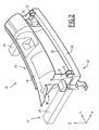
- FIGS. 1 and 2 illustrate, in a simplified manner, a part of a front bumper 10 intended to be mounted on a structure 12 of a motor vehicle.
- the bumper 10 comprises a bumper reinforcement 14 extending substantially transversely to the vehicle and having a first lower portion 16 and a second upper portion 18.
- the lower part 16 is equipped, on either side of the frame 14, with a compensating part 20 mounted on the frame 14.
- the structure 12 comprises a base 22 whose front part comprises among others two side members 24 interconnected by means of a transverse beam 26, the latter being screwed to the front end of each side member 24.
- the front part of the underframe 22 also comprises mounting brackets 28 for fixing the bumper 10 to the structure 12. On either side of the base 22, on each spar 24 is fixed a fixing support 28.
- the fastening supports 28 constitute precise geometrical references for positioning and fixing the bumper 10 on the structure 12. Each support 28 is accurately positioned on the underbody 22 at a manufacturing stage where the geometry of the vehicle is stabilized. .
- the beam 26 constitutes, by its attachment to the longitudinal members 24, a non-specific geometric reference, as will be explained in more detail later.
- the upper portion 18 of the frame 14 is adapted to be fixed on the fixing brackets 28 by a zone 30 for positioning and fixing.
- the lower part 16 is able to rest on the beam 26 via the compensation parts 20.
- each piece 20 has a substantially U-shaped coated, and is slidably mounted on the frame 14 in a substantially vertical direction.
- a slot 32 of oblong shape is formed in the U core of the part 20 and extends in the vertical direction.
- a system 34 for example a screw-nut assembly, makes it possible to guide the vertical sliding of the part 20 and also makes it possible to lock the part 20 in position by clamping.
- a notched system can participate in the locking of the part 20 on the frame 14.
- the light 32 comprises a succession of notches which are intended to cooperate with the clamping screw.
- the part of the part 20 intended to bear against the reinforcement 14 and / or the zone of the armature 14 bearing against this compensation part 20 comprise ribs and or grooves forming a detent, which allows a quick adjustment of the position of the compensation part 20 against the beam 26.
- a quarter turn assembly is used, which allows a quick adjustment of the position of the compensation part 20 against the beam 26, which allows a quick fixing of the compensation part 20 against the beam 26.
- the piece 20 has a substantially L-shaped shape, the slot 32 being provided in the vertical leg of L.
- the upper part 18 of the armature 14 is positioned and fixed on the fixing supports 28 at the zones 30.
- the lower part 16 of the armature 14 does not rest on the beam 26; there is a clearance between the compensation parts 20 and the upper surface 36 of the beam 26.
- the installation of the armature 14 on the structure 12 is then completed by moving, more precisely by sliding vertically, the parts 20 so as to bring them in contact with the surface 36, position shown in phantom on the Figures 3 and 4 .
- the invention therefore makes it possible to have a minimum of geometrical references upstream of the mounting stage of the bumper on the structure of the vehicle, and to adapt the other references as a function of the geometry of the various elements; the aesthetics of the vehicle is improved.
Description
La présente invention concerne un procédé de montage d'un pare-chocs sur une structure de véhicule automobile, le pare-chocs comprenant une armature de pare-chocs et la structure comprenant un soubassement formé d'une poutre transversale, de longerons et de supports de fixation portés par les longerons, procédé du type selon lequel on positionne et on fixe l'armature sur la structure par rapport à des références géométriques prédéterminées dont certaines sont solidaires des supports de fixation tandis que d'autres sont solidaires de la poutre.
On connait par les documents
We know from the documents
Aujourd'hui, ces références, c'est-à-dire les éléments tels que les indexages et les fixations qui permettent la mise en place du pare-chocs sur la structure du véhicule, sont créées très tôt dans le synoptique du montage et à des stades d'assemblage différents, ce qui engendre des dispersions géométriques entre elles.Today, these references, that is to say elements such as indexings and fixings that allow the installation of the bumper on the vehicle structure, are created very early in the synoptic of the assembly and to different assembly stages, which generates geometrical dispersions between them.
Toutefois, une fois l'armature agencée sur la structure, il convient que le pare-chocs respecte certaines cotations, comme par exemple sa position par rapport aux éléments de carrosserie environnants. Les jeux et affleurements entre le pare-chocs et l'aile, le capot moteur ou un bloc optique par exemple, doivent être maîtrisés afin de garantir une certaine qualité perçue.However, once the armature is arranged on the structure, it is appropriate that the bumper respects certain dimensions, such as its position relative to the surrounding bodywork elements. Games and outcrops between the bumper and the wing, the bonnet or an optical block for example, must be controlled to ensure a certain perceived quality.
De plus, le pare-chocs ainsi que certains éléments de la structure ont également leurs propres dispersions géométriques.In addition, the bumper and some elements of the structure also have their own geometric dispersions.
L'invention a pour but de proposer un procédé simple et peu coûteux de montage du pare-chocs sur la structure qui permette de prendre en considération les différentes dispersions géométriques et donc d'améliorer l'esthétique du véhicule en terme de qualité perçue.The invention aims to provide a simple and inexpensive method of mounting the bumper on the structure that allows to take into account the different geometric dispersions and thus improve the aesthetics of the vehicle in terms of perceived quality.
A cet effet, l'invention a pour objet un procédé du type précité, caractérisé en ce que :
- on équipe une première partie de l'armature de pièces de compensation montées réglables sur l'armature ;
- on fixe une deuxième partie de l'armature sur les supports de fixation, la position des pièces de compensation étant telle qu'elles sont espacées de la poutre lorsque ladite fixation a été réalisée ; et
- on complète la mise en place de l'armature sur la structure en déplaçant les pièces de compensation de manière à les amener en contact avec la poutre.
- a first part of the frame is fitted with adjustable compensation pieces mounted on the frame;
- attaching a second part of the frame to the mounting brackets, the position of the compensation parts being such that they are spaced from the beam when said fixing has been made; and
- it completes the establishment of the frame on the structure by moving the compensation parts so as to bring them into contact with the beam.
Le procédé selon l'invention peut comporter une ou plusieurs des caractéristiques suivantes :
- les pièces de compensation sont montées coulissantes sur l'armature ; et
- les pièces de compensation sont montées coulissantes sur l'armature suivant une direction sensiblement verticale.
- the compensation parts are slidably mounted on the frame; and
- the compensation parts are slidably mounted on the frame in a substantially vertical direction.
L'invention a également pour objet un pare-chocs destiné à être monté sur une structure de véhicule automobile, du type comprenant une armature de pare-chocs, la structure comprenant un soubassement formé d'une poutre transversale, de longerons et de supports de fixation portés par les longerons, caractérisé en ce que ladite armature de pare-chocs (14) comprend une première partie (16) équipée de pièces de compensation (20) montées réglables sur l'armature (14) et propres à être amenées d'une première position où elles sont espacées de ladite poutre (26) après la fixation d'une deuxième partie (18) de l'armature (14) sur lesdits supports de fixation (28) à une seconde position où elles sont en contact avec ladite poutre (26). The invention also relates to a bumper intended to be mounted on a motor vehicle structure, of the type comprising a bumper reinforcement, the structure comprising a base formed of a transverse beam, longitudinal members and support brackets. fixation carried by the side members, characterized in that said bumper frame (14) comprises a first portion (16) equipped with compensation pieces (20) mounted to be adjustable on the frame (14) and adapted to be brought from a first position where they are spaced from said beam (26) after attaching a second portion (18) of the frame (14) to said attachment brackets (28) at a second position where they are in contact with said beam (26).
Le pare-chocs selon l'invention peut comporter une ou plusieurs des caractéristiques suivantes :
- les pièces de compensation sont montées coulissantes sur l'armature ;
- les pièces de compensation sont montées coulissantes sur l'armature suivant une direction sensiblement verticale ; et
- les pièces de compensation présentent une forme sensiblement en U ou en L.
- the compensation parts are slidably mounted on the frame;
- the compensation parts are slidably mounted on the armature in a substantially vertical direction; and
- the compensation parts have a substantially U-shaped or L-shaped.
L'invention a en outre pour objet un véhicule automobile, du type comportant une structure comprenant un soubassement formé d'une poutre transversale, de longerons et de supports de fixation portés par les longerons, caractérisé en ce qu'il comporte un pare-chocs tel que décrit précédemment, fixé sur les supports de fixation et en appui sur la poutre.The invention further relates to a motor vehicle, of the type comprising a structure comprising a base formed of a transverse beam, longitudinal members and mounting brackets carried by the side members, characterized in that it comprises a bumper as described above, fixed on the mounting brackets and supported on the beam.
Le véhicule automobile selon l'invention peut comporter la caractéristique selon laquelle le pare-chocs est un pare-chocs avant.The motor vehicle according to the invention may include the characteristic that the bumper is a front bumper.
L'invention sera mieux comprise à la lecture de la description qui va suivre, donnée uniquement à titre d'exemple et faite en se référant aux dessins annexés, sur lesquels :
- la
Figure 1 est une vue en perspective montrant un pare-chocs selon l'invention avant son montage sur une structure de véhicule automobile ; - la
Figure 2 est une vue similaire à celle de laFigure 1 montrant une étape intermédiaire du montage ; - la
Figure 3 est une vue en perspective agrandie montrant une pièce de compensation selon un premier mode de réalisation de l'invention et lors de l'étape finale du montage ; et - la
Figure 4 est une vue similaire à celle de laFigure 3 montrant une pièce de compensation selon un deuxième mode de réalisation de l'invention.
- the
Figure 1 is a perspective view showing a bumper according to the invention before it is mounted on a motor vehicle structure; - the
Figure 2 is a view similar to that of theFigure 1 showing an intermediate stage of assembly; - the
Figure 3 is an enlarged perspective view showing a compensation part according to a first embodiment of the invention and during the final stage of assembly; and - the
Figure 4 is a view similar to that of theFigure 3 showing a compensation part according to a second embodiment of the invention.
Afin de simplifier la description qui va suivre, les Figures ont été orientées suivant le système d'axes X, Y, Z définissant l'orientation usuelle d'un véhicule automobile, et dans lequel :
- l'axe X est l'axe longitudinal du véhicule, orienté d'arrière en avant ;
- l'axe Y est l'axe transversal orienté de droite à gauche ; et
- l'axe Z est l'axe vertical orienté du bas vers le haut.
- the X axis is the longitudinal axis of the vehicle, oriented from rear to front;
- the Y axis is the transverse axis oriented from right to left; and
- the Z axis is the vertical axis oriented from bottom to top.
Les termes de position et d'orientation qui sont utilisés par la suite s'entendent par rapport à ce système d'axes.The terms of position and orientation that are used subsequently agree with respect to this axis system.
Les
Le pare-chocs 10 comprend une armature de pare-chocs 14 s'étendant sensiblement transversalement par rapport au véhicule et comportant une première partie inférieure 16 et une deuxième partie supérieure 18.The
La partie inférieure 16 est équipée, de part et d'autre de l'armature 14, d'une pièce de compensation 20 montée réglable sur l'armature 14.The
La structure 12 comprend un soubassement 22 dont la partie avant comporte entre autres deux longerons 24 reliés entre eux au moyen d'une poutre transversale 26, cette dernière étant montée par vissage à l'extrémité avant de chaque longeron 24.The
La partie avant du soubassement 22 comprend également des supports de fixation 28 destinés à la fixation du pare-chocs 10 sur la structure 12. De part et d'autre du soubassement 22, sur chaque longeron 24 est fixé un support de fixation 28.The front part of the
Les supports de fixation 28 constituent des références géométriques précises pour le positionnement et la fixation du pare-chocs 10 sur la structure 12. Chaque support 28 est positionné de façon précise sur le soubassement 22 à un stade de fabrication où la géométrie du véhicule est stabilisée. A contrario, la poutre 26 constitue, de par sa fixation sur les longerons 24, une référence géométrique non précise, comme cela sera expliqué plus en détail ultérieurement.The fastening supports 28 constitute precise geometrical references for positioning and fixing the
La partie supérieure 18 de l'armature 14 est adaptée pour être fixée sur les supports de fixation 28 par une zone 30 de positionnement et de fixation.The
La partie inférieure 16 est propre à s'appuyer sur la poutre 26 par l'intermédiaire des pièces de compensation 20.The
Comme on le voit mieux sur la
Pour cela, une lumière 32 de forme oblongue est ménagée dans l'âme du U de la pièce 20 et s'étend dans la direction verticale.For this, a
Un système 34, par exemple un ensemble vis-écrou, permet de guider le coulissement vertical de la pièce 20 et permet également de verrouiller par serrage la pièce 20 en position.A
Selon une variante de réalisation du système 34, non représentée mais donnée à titre d'exemple non limitatif, un système cranté peut participer au verrouillage de la pièce 20 sur l'armature 14. Pour cela, la lumière 32 comprend une succession de crans qui sont destinés à coopérer avec la vis de serrage. Dans un autre mode de réalisation du système de crantage, la partie de la pièce 20 destinée à venir en appui contre l'armature 14 et/ou la zone de l'armature 14 venant en appui contre cette pièce de compensation 20 comprennent des nervures et/ou rainures formant crantage, ce qui permet un réglage rapide de la position de la pièce de compensation 20 contre la poutre 26.According to an alternative embodiment of the
Selon une variante de réalisation du moyen de serrage de la pièce 20 contre l'armature 14, un ensemble quart de tour est utilisé, ce qui permet un réglage rapide de la position de la pièce de compensation 20 contre la poutre 26, ce qui permet une fixation rapide de la pièce de compensation 20 contre la poutre 26.According to an alternative embodiment of the clamping means of the
En variante et comme illustré sur la
Lors du montage du pare-chocs 10 sur la structure 12, on positionne et on fixe la partie supérieure 18 de l'armature 14 sur les supports de fixation 28 au niveau des zones 30.During assembly of the
Dans cette position et suite aux dispersions géométriques subies par les différents éléments, la partie inférieure 16 de l'armature 14 ne repose pas sur la poutre 26 ; il y a un jeu entre les pièces de compensation 20 et la surface supérieure 36 de la poutre 26.In this position and following the geometrical dispersions experienced by the various elements, the
Cette position des pièces 20 espacées de la poutre 26 est représentée en traits pleins sur les
On complète alors la mise en place de l'armature 14 sur la structure 12 en déplaçant, plus précisément en faisant coulisser verticalement, les pièces 20 de manière à les amener en contact avec la surface 36, position représentée en traits mixtes sur les
Ainsi, le jeu entre les pièces 20 et la poutre 26 est rattrapé et la partie inférieure 16 de l'armature 14 est en appui sur la poutre 26.Thus, the clearance between the
L'invention permet donc de disposer d'un minimum de références géométriques en amont du stade de montage du pare-chocs sur la structure du véhicule, et d'adapter les autres références en fonction de la géométrie des différents éléments ; l'esthétique du véhicule s'en trouve améliorée.The invention therefore makes it possible to have a minimum of geometrical references upstream of the mounting stage of the bumper on the structure of the vehicle, and to adapt the other references as a function of the geometry of the various elements; the aesthetics of the vehicle is improved.
Claims (8)
- A method for mounting a bumper (10) on a structure (12) of an automobile, the bumper (10) including a bumper armature (14) and the structure (12) including an understructure (22) formed by a transverse beam (26), side rails (24) and attachment supports (28) carried by the side rails (24), a method of the type according to which the armature (14) is positioned and fixed on the structure (12) with respect to predetermined geometrical references, some of which are integral with the attachment supports (28) whereas others are integral with the beam (26), characterized in that:- a first portion (16) of the armature (14) is equipped with compensation parts (20) adjustably mounted on the armature (14);- a second portion (18) of the armature (14) is fixed on the attachment supports (28), the position of the compensation parts (20) being such that they are spaced from the beam (26) when the said attachment has been carried out; and- the placing of the armature (14) on the structure (12) is completed by moving the compensation parts (20) so as to bring them in contact with the beam (26).
- The method according to Claim 1, characterized in that the compensation parts (20) are slidably mounted on the armature (14).
- The method according to Claim 2, characterized in that the compensation parts (20) are slidably mounted on the armature (14) along a substantially vertical direction.
- An automobile comprising a structure (12) including an understructure (22) formed by a transverse beam (26), side rails (24) and attachment supports (28) carried by the side rails (24), and a bumper (10) fixed on the attachment supports (28) and resting on the beam (26) and including a bumper armature (14), characterized in that the said bumper armature (14) includes a first portion (16) equipped with compensation parts (20) adjustably mounted on the armature (14) and suited to be brought from a first position in which they are spaced from the said beam (26) after the attaching of a second portion (18) of the armature (14) on the said attachment supports (28) to a second position in which they are in contact with the said beam (26).
- The automobile according to Claim 4, characterized in that the compensation parts (20) are slidably mounted on the armature (14).
- The automobile according to Claim 5, characterized in that the compensation parts (20) are slidably mounted on the armature (14) along a substantially vertical direction.
- The automobile according to any one of Claims 4 to 6, characterized in that the compensation parts (20) have substantially a U or L shape.
- The automobile according to any one of Claims 4 to 7, characterized in that the bumper (10) is a front bumper.
Applications Claiming Priority (2)
| Application Number | Priority Date | Filing Date | Title |
|---|---|---|---|
| FR0756751A FR2919263B1 (en) | 2007-07-26 | 2007-07-26 | METHOD FOR MOUNTING A BUMPER ON A MOTOR VEHICLE STRUCTURE |
| PCT/FR2008/050876 WO2009013416A1 (en) | 2007-07-26 | 2008-05-21 | Method for mounting a bumper on the structure of an automobile |
Publications (2)
| Publication Number | Publication Date |
|---|---|
| EP2170685A1 EP2170685A1 (en) | 2010-04-07 |
| EP2170685B1 true EP2170685B1 (en) | 2013-07-10 |
Family
ID=39165805
Family Applications (1)
| Application Number | Title | Priority Date | Filing Date |
|---|---|---|---|
| EP08805822.7A Not-in-force EP2170685B1 (en) | 2007-07-26 | 2008-05-21 | Method for mounting a bumper on the structure of an automobile |
Country Status (6)
| Country | Link |
|---|---|
| EP (1) | EP2170685B1 (en) |
| CN (1) | CN101765536B (en) |
| BR (1) | BRPI0811654A2 (en) |
| FR (1) | FR2919263B1 (en) |
| RU (1) | RU2457972C2 (en) |
| WO (1) | WO2009013416A1 (en) |
Families Citing this family (10)
| Publication number | Priority date | Publication date | Assignee | Title |
|---|---|---|---|---|
| FR2900617A1 (en) * | 2006-05-04 | 2007-11-09 | Peugeot Citroen Automobiles Sa | VEHICLE COMPRISING AN ARMATURE AS A SUPPORT FOR A BUMPER |
| FR2941899B1 (en) * | 2009-02-06 | 2012-08-10 | Peugeot Citroen Automobiles Sa | STRUCTURE OF THE FRONT OF THE BODY OF A MOTOR VEHICLE AND VEHICLE COMPRISING SUCH A STRUCTURE |
| FR2943609B1 (en) * | 2009-03-25 | 2011-06-10 | Renault Sas | ARRANGEMENT FOR A FRONT PART OF A MOTOR VEHICLE |
| FR2952027B1 (en) * | 2009-11-05 | 2012-04-27 | Peugeot Citroen Automobiles Sa | VEHICLE STRUCTURE ELEMENT FOR HOLDING A BUMPER FRAME |
| FR2959202B1 (en) * | 2010-04-27 | 2012-04-27 | Peugeot Citroen Automobiles Sa | FIXING METHOD FOR RACK SUPPORT ON A BUMPER BEAM |
| JP6070393B2 (en) * | 2013-05-07 | 2017-02-01 | スズキ株式会社 | Vehicle front structure |
| FR3071035B1 (en) * | 2017-09-12 | 2019-08-23 | Psa Automobiles Sa | OPTICAL VEHICLE BLOCK WITH TRANSLUCENT SCREEN SUSPENDED WITH A MASK |
| CN108639152B (en) * | 2018-04-09 | 2020-07-07 | 吉利汽车研究院(宁波)有限公司 | Automobile front end assembly mounting method and automobile front end assembly |
| FR3121093B1 (en) * | 2021-03-26 | 2023-02-10 | Psa Automobiles Sa | ATTACHMENT INTERFACE OF AN EXTERIOR VEHICLE EQUIPMENT |
| FR3133809B1 (en) * | 2022-03-24 | 2024-02-09 | Psa Automobiles Sa | VEHICLE FRONT FACADE WITH SIMPLIFIED COUPLING OF THE BUMPER FRAME |
Family Cites Families (8)
| Publication number | Priority date | Publication date | Assignee | Title |
|---|---|---|---|---|
| FR2615156B1 (en) * | 1987-05-13 | 1989-08-18 | Peugeot Aciers Et Outillage | MODULAR STRUCTURE FOR VEHICLE AND ITS APPLICATION TO THE AUTOMATIC ASSEMBLY THEREOF |
| JP2508639Y2 (en) * | 1990-07-17 | 1996-08-28 | スズキ株式会社 | Automotive bumper mounting structure |
| JP2000016206A (en) * | 1998-07-03 | 2000-01-18 | Suzuki Motor Corp | Bumper mounting structure |
| US6282769B1 (en) * | 1998-07-15 | 2001-09-04 | Cosma International Inc. | Motor vehicle end module assembly |
| FR2816273B1 (en) * | 2000-11-06 | 2003-02-28 | Valeo Thermique Moteur Sa | FRONT PANEL OF MOTOR VEHICLE INCLUDING A BUMPER BEAM |
| JP4762444B2 (en) * | 2001-06-15 | 2011-08-31 | 富士重工業株式会社 | Vehicle front-end structure |
| RU33069U1 (en) * | 2003-04-28 | 2003-10-10 | Открытое акционерное общество "АВТОВАЗ" | ENERGY-ABSORBING PART OF THE CAR |
| FR2890621B1 (en) * | 2005-09-09 | 2007-10-19 | Valeo Systemes Thermiques | FRONT PANEL FOR MOTOR VEHICLE |
-
2007
- 2007-07-26 FR FR0756751A patent/FR2919263B1/en not_active Expired - Fee Related
-
2008
- 2008-05-21 WO PCT/FR2008/050876 patent/WO2009013416A1/en active Application Filing
- 2008-05-21 BR BRPI0811654-7A2A patent/BRPI0811654A2/en not_active IP Right Cessation
- 2008-05-21 CN CN2008801004943A patent/CN101765536B/en active Active
- 2008-05-21 EP EP08805822.7A patent/EP2170685B1/en not_active Not-in-force
- 2008-05-21 RU RU2010107053/11A patent/RU2457972C2/en active
Also Published As
| Publication number | Publication date |
|---|---|
| WO2009013416A1 (en) | 2009-01-29 |
| EP2170685A1 (en) | 2010-04-07 |
| CN101765536B (en) | 2012-08-22 |
| RU2010107053A (en) | 2011-09-10 |
| RU2457972C2 (en) | 2012-08-10 |
| FR2919263B1 (en) | 2009-11-13 |
| FR2919263A1 (en) | 2009-01-30 |
| CN101765536A (en) | 2010-06-30 |
| BRPI0811654A2 (en) | 2015-02-10 |
Similar Documents
| Publication | Publication Date | Title |
|---|---|---|
| EP2170685B1 (en) | Method for mounting a bumper on the structure of an automobile | |
| EP0720935B1 (en) | Device for precise positioning of a bumper to a vehicle fender portion | |
| FR2783797A1 (en) | MOTOR VEHICLE, FRONT BLOCK FOR THIS VEHICLE AND METHOD OF MOUNTING THE VEHICLE | |
| EP2914476B1 (en) | Device for attaching two structural parts to each other, comprising a floating positioning element | |
| WO2014057217A1 (en) | Method for producing and installing a front end of a motor vehicle | |
| FR2930203A1 (en) | Slide for seat of motor vehicle, has projecting member comprising retaining element supported on lower surface of core and locking orifice in which stamping portion integrated to side flank of central part of movable profile is inserted | |
| FR2916167A3 (en) | Mounting rail for e.g. rear left seat in motor coach, has longitudinal hollow wall to rigidly associate and connect two guides that support and guide seat, where one guide is parallel to other guide and transversally moved from latter guide | |
| EP2062804B1 (en) | Device and method for attaching a wing assembly to an automobile body shell wall | |
| EP1916152B2 (en) | Front-end structure of a vehicle and associated automobile | |
| EP2132055B1 (en) | Method for mounting a transverse understructure member and a technical front panel | |
| EP3433161B1 (en) | Lateral assembly with doors opening for motor vehicle and associated assembly method | |
| FR2977841A3 (en) | CENTER CONSOLE FOR MOTOR VEHICLE | |
| FR3097484A1 (en) | System including a vehicle seat slide and bracket | |
| EP2734396B1 (en) | Simply articulated fuel flap and method of mounting it to a vehicle | |
| FR2921040A1 (en) | Rear bumper skin assembling method for motor vehicle, involves positioning support on each side of opening for rear bumper skin, fixing supports on bodies of motor vehicle, and fixing rear bumper skin on supports | |
| EP1610005B1 (en) | Clip for the attachment of a screw to parts of an automobile | |
| EP3452359B1 (en) | Interface for mounting a steering column and associated mounting method | |
| EP4147894A1 (en) | Positioning and holding arrangement for a sliding door of a vehicle | |
| EP2045171B1 (en) | Front module for motor vehicles and related assembling method | |
| WO2015082793A1 (en) | Motor vehicle comprising a chassis delimited by horizontal and vertical side flanks and an associated valance | |
| FR3079173A1 (en) | METHOD AND DEVICE FOR MOUNTING A GEARBOX CONTROL ON A VEHICLE | |
| FR2928128A1 (en) | FRONT ASSEMBLY OF A MOTOR VEHICLE COMPRISING A FRONT PROJECTOR | |
| FR2999490A1 (en) | SLIDING ASSEMBLY FOR A VEHICLE SEAT AND VEHICLE SEAT COMPRISING SUCH AN ASSEMBLY | |
| FR2665125A1 (en) | Device for fixing and method for mounting a motor vehicle sliding seat | |
| FR2920741A1 (en) | Front right headlamp, front right wing and front bumper assembly for motor vehicle, has headlamp fixed to respective edges of front right wing and front bumper, and support piece supported against projection of headlamp |
Legal Events
| Date | Code | Title | Description |
|---|---|---|---|
| PUAI | Public reference made under article 153(3) epc to a published international application that has entered the european phase |
Free format text: ORIGINAL CODE: 0009012 |
|
| 17P | Request for examination filed |
Effective date: 20091217 |
|
| AK | Designated contracting states |
Kind code of ref document: A1 Designated state(s): AT BE BG CH CY CZ DE DK EE ES FI FR GB GR HR HU IE IS IT LI LT LU LV MC MT NL NO PL PT RO SE SI SK TR |
|
| AX | Request for extension of the european patent |
Extension state: AL BA MK RS |
|
| RIN1 | Information on inventor provided before grant (corrected) |
Inventor name: LEPINE, ARNAUD Inventor name: REMY, STEPHANE |
|
| 17Q | First examination report despatched |
Effective date: 20100610 |
|
| DAX | Request for extension of the european patent (deleted) | ||
| GRAP | Despatch of communication of intention to grant a patent |
Free format text: ORIGINAL CODE: EPIDOSNIGR1 |
|
| GRAS | Grant fee paid |
Free format text: ORIGINAL CODE: EPIDOSNIGR3 |
|
| GRAA | (expected) grant |
Free format text: ORIGINAL CODE: 0009210 |
|
| AK | Designated contracting states |
Kind code of ref document: B1 Designated state(s): AT BE BG CH CY CZ DE DK EE ES FI FR GB GR HR HU IE IS IT LI LT LU LV MC MT NL NO PL PT RO SE SI SK TR |
|
| REG | Reference to a national code |
Ref country code: GB Ref legal event code: FG4D Free format text: NOT ENGLISH |
|
| REG | Reference to a national code |
Ref country code: AT Ref legal event code: REF Ref document number: 620800 Country of ref document: AT Kind code of ref document: T Effective date: 20130715 Ref country code: CH Ref legal event code: EP |
|
| REG | Reference to a national code |
Ref country code: IE Ref legal event code: FG4D Free format text: LANGUAGE OF EP DOCUMENT: FRENCH |
|
| REG | Reference to a national code |
Ref country code: DE Ref legal event code: R096 Ref document number: 602008025955 Country of ref document: DE Effective date: 20130905 |
|
| PG25 | Lapsed in a contracting state [announced via postgrant information from national office to epo] |
Ref country code: SI Free format text: LAPSE BECAUSE OF FAILURE TO SUBMIT A TRANSLATION OF THE DESCRIPTION OR TO PAY THE FEE WITHIN THE PRESCRIBED TIME-LIMIT Effective date: 20130710 |
|
| REG | Reference to a national code |
Ref country code: AT Ref legal event code: MK05 Ref document number: 620800 Country of ref document: AT Kind code of ref document: T Effective date: 20130710 |
|
| REG | Reference to a national code |
Ref country code: NL Ref legal event code: VDEP Effective date: 20130710 |
|
| REG | Reference to a national code |
Ref country code: LT Ref legal event code: MG4D |
|
| PG25 | Lapsed in a contracting state [announced via postgrant information from national office to epo] |
Ref country code: HR Free format text: LAPSE BECAUSE OF FAILURE TO SUBMIT A TRANSLATION OF THE DESCRIPTION OR TO PAY THE FEE WITHIN THE PRESCRIBED TIME-LIMIT Effective date: 20130710 Ref country code: CY Free format text: LAPSE BECAUSE OF FAILURE TO SUBMIT A TRANSLATION OF THE DESCRIPTION OR TO PAY THE FEE WITHIN THE PRESCRIBED TIME-LIMIT Effective date: 20130821 Ref country code: NO Free format text: LAPSE BECAUSE OF FAILURE TO SUBMIT A TRANSLATION OF THE DESCRIPTION OR TO PAY THE FEE WITHIN THE PRESCRIBED TIME-LIMIT Effective date: 20131010 Ref country code: SE Free format text: LAPSE BECAUSE OF FAILURE TO SUBMIT A TRANSLATION OF THE DESCRIPTION OR TO PAY THE FEE WITHIN THE PRESCRIBED TIME-LIMIT Effective date: 20130710 Ref country code: IS Free format text: LAPSE BECAUSE OF FAILURE TO SUBMIT A TRANSLATION OF THE DESCRIPTION OR TO PAY THE FEE WITHIN THE PRESCRIBED TIME-LIMIT Effective date: 20131110 Ref country code: PT Free format text: LAPSE BECAUSE OF FAILURE TO SUBMIT A TRANSLATION OF THE DESCRIPTION OR TO PAY THE FEE WITHIN THE PRESCRIBED TIME-LIMIT Effective date: 20131111 Ref country code: AT Free format text: LAPSE BECAUSE OF FAILURE TO SUBMIT A TRANSLATION OF THE DESCRIPTION OR TO PAY THE FEE WITHIN THE PRESCRIBED TIME-LIMIT Effective date: 20130710 Ref country code: LT Free format text: LAPSE BECAUSE OF FAILURE TO SUBMIT A TRANSLATION OF THE DESCRIPTION OR TO PAY THE FEE WITHIN THE PRESCRIBED TIME-LIMIT Effective date: 20130710 |
|
| PG25 | Lapsed in a contracting state [announced via postgrant information from national office to epo] |
Ref country code: FI Free format text: LAPSE BECAUSE OF FAILURE TO SUBMIT A TRANSLATION OF THE DESCRIPTION OR TO PAY THE FEE WITHIN THE PRESCRIBED TIME-LIMIT Effective date: 20130710 Ref country code: ES Free format text: LAPSE BECAUSE OF FAILURE TO SUBMIT A TRANSLATION OF THE DESCRIPTION OR TO PAY THE FEE WITHIN THE PRESCRIBED TIME-LIMIT Effective date: 20131021 Ref country code: GR Free format text: LAPSE BECAUSE OF FAILURE TO SUBMIT A TRANSLATION OF THE DESCRIPTION OR TO PAY THE FEE WITHIN THE PRESCRIBED TIME-LIMIT Effective date: 20131011 Ref country code: PL Free format text: LAPSE BECAUSE OF FAILURE TO SUBMIT A TRANSLATION OF THE DESCRIPTION OR TO PAY THE FEE WITHIN THE PRESCRIBED TIME-LIMIT Effective date: 20130710 Ref country code: NL Free format text: LAPSE BECAUSE OF FAILURE TO SUBMIT A TRANSLATION OF THE DESCRIPTION OR TO PAY THE FEE WITHIN THE PRESCRIBED TIME-LIMIT Effective date: 20130710 Ref country code: LV Free format text: LAPSE BECAUSE OF FAILURE TO SUBMIT A TRANSLATION OF THE DESCRIPTION OR TO PAY THE FEE WITHIN THE PRESCRIBED TIME-LIMIT Effective date: 20130710 |
|
| PG25 | Lapsed in a contracting state [announced via postgrant information from national office to epo] |
Ref country code: CY Free format text: LAPSE BECAUSE OF FAILURE TO SUBMIT A TRANSLATION OF THE DESCRIPTION OR TO PAY THE FEE WITHIN THE PRESCRIBED TIME-LIMIT Effective date: 20130710 |
|
| PG25 | Lapsed in a contracting state [announced via postgrant information from national office to epo] |
Ref country code: DK Free format text: LAPSE BECAUSE OF FAILURE TO SUBMIT A TRANSLATION OF THE DESCRIPTION OR TO PAY THE FEE WITHIN THE PRESCRIBED TIME-LIMIT Effective date: 20130710 Ref country code: SK Free format text: LAPSE BECAUSE OF FAILURE TO SUBMIT A TRANSLATION OF THE DESCRIPTION OR TO PAY THE FEE WITHIN THE PRESCRIBED TIME-LIMIT Effective date: 20130710 Ref country code: EE Free format text: LAPSE BECAUSE OF FAILURE TO SUBMIT A TRANSLATION OF THE DESCRIPTION OR TO PAY THE FEE WITHIN THE PRESCRIBED TIME-LIMIT Effective date: 20130710 Ref country code: CZ Free format text: LAPSE BECAUSE OF FAILURE TO SUBMIT A TRANSLATION OF THE DESCRIPTION OR TO PAY THE FEE WITHIN THE PRESCRIBED TIME-LIMIT Effective date: 20130710 Ref country code: RO Free format text: LAPSE BECAUSE OF FAILURE TO SUBMIT A TRANSLATION OF THE DESCRIPTION OR TO PAY THE FEE WITHIN THE PRESCRIBED TIME-LIMIT Effective date: 20130710 |
|
| PLBE | No opposition filed within time limit |
Free format text: ORIGINAL CODE: 0009261 |
|
| STAA | Information on the status of an ep patent application or granted ep patent |
Free format text: STATUS: NO OPPOSITION FILED WITHIN TIME LIMIT |
|
| PG25 | Lapsed in a contracting state [announced via postgrant information from national office to epo] |
Ref country code: IT Free format text: LAPSE BECAUSE OF FAILURE TO SUBMIT A TRANSLATION OF THE DESCRIPTION OR TO PAY THE FEE WITHIN THE PRESCRIBED TIME-LIMIT Effective date: 20130710 |
|
| 26N | No opposition filed |
Effective date: 20140411 |
|
| REG | Reference to a national code |
Ref country code: DE Ref legal event code: R097 Ref document number: 602008025955 Country of ref document: DE Effective date: 20140411 |
|
| REG | Reference to a national code |
Ref country code: DE Ref legal event code: R084 Ref document number: 602008025955 Country of ref document: DE |
|
| REG | Reference to a national code |
Ref country code: GB Ref legal event code: 746 Effective date: 20140805 |
|
| REG | Reference to a national code |
Ref country code: DE Ref legal event code: R084 Ref document number: 602008025955 Country of ref document: DE Effective date: 20140801 |
|
| PG25 | Lapsed in a contracting state [announced via postgrant information from national office to epo] |
Ref country code: LU Free format text: LAPSE BECAUSE OF FAILURE TO SUBMIT A TRANSLATION OF THE DESCRIPTION OR TO PAY THE FEE WITHIN THE PRESCRIBED TIME-LIMIT Effective date: 20140521 |
|
| REG | Reference to a national code |
Ref country code: CH Ref legal event code: PL |
|
| PG25 | Lapsed in a contracting state [announced via postgrant information from national office to epo] |
Ref country code: MC Free format text: LAPSE BECAUSE OF FAILURE TO SUBMIT A TRANSLATION OF THE DESCRIPTION OR TO PAY THE FEE WITHIN THE PRESCRIBED TIME-LIMIT Effective date: 20130710 Ref country code: CH Free format text: LAPSE BECAUSE OF NON-PAYMENT OF DUE FEES Effective date: 20140531 Ref country code: LI Free format text: LAPSE BECAUSE OF NON-PAYMENT OF DUE FEES Effective date: 20140531 |
|
| REG | Reference to a national code |
Ref country code: IE Ref legal event code: MM4A |
|
| PG25 | Lapsed in a contracting state [announced via postgrant information from national office to epo] |
Ref country code: IE Free format text: LAPSE BECAUSE OF NON-PAYMENT OF DUE FEES Effective date: 20140521 |
|
| PG25 | Lapsed in a contracting state [announced via postgrant information from national office to epo] |
Ref country code: MT Free format text: LAPSE BECAUSE OF FAILURE TO SUBMIT A TRANSLATION OF THE DESCRIPTION OR TO PAY THE FEE WITHIN THE PRESCRIBED TIME-LIMIT Effective date: 20130710 |
|
| REG | Reference to a national code |
Ref country code: FR Ref legal event code: PLFP Year of fee payment: 9 |
|
| PG25 | Lapsed in a contracting state [announced via postgrant information from national office to epo] |
Ref country code: BG Free format text: LAPSE BECAUSE OF FAILURE TO SUBMIT A TRANSLATION OF THE DESCRIPTION OR TO PAY THE FEE WITHIN THE PRESCRIBED TIME-LIMIT Effective date: 20130710 |
|
| PG25 | Lapsed in a contracting state [announced via postgrant information from national office to epo] |
Ref country code: BE Free format text: LAPSE BECAUSE OF FAILURE TO SUBMIT A TRANSLATION OF THE DESCRIPTION OR TO PAY THE FEE WITHIN THE PRESCRIBED TIME-LIMIT Effective date: 20140531 Ref country code: TR Free format text: LAPSE BECAUSE OF FAILURE TO SUBMIT A TRANSLATION OF THE DESCRIPTION OR TO PAY THE FEE WITHIN THE PRESCRIBED TIME-LIMIT Effective date: 20130710 Ref country code: HU Free format text: LAPSE BECAUSE OF FAILURE TO SUBMIT A TRANSLATION OF THE DESCRIPTION OR TO PAY THE FEE WITHIN THE PRESCRIBED TIME-LIMIT; INVALID AB INITIO Effective date: 20080521 |
|
| REG | Reference to a national code |
Ref country code: FR Ref legal event code: PLFP Year of fee payment: 10 |
|
| PGFP | Annual fee paid to national office [announced via postgrant information from national office to epo] |
Ref country code: GB Payment date: 20170426 Year of fee payment: 10 |
|
| REG | Reference to a national code |
Ref country code: FR Ref legal event code: PLFP Year of fee payment: 11 |
|
| REG | Reference to a national code |
Ref country code: FR Ref legal event code: CA Effective date: 20180312 Ref country code: FR Ref legal event code: CD Owner name: PEUGEOT CITROEN AUTOMOBILES SA, FR Effective date: 20180312 |
|
| GBPC | Gb: european patent ceased through non-payment of renewal fee |
Effective date: 20180521 |
|
| PG25 | Lapsed in a contracting state [announced via postgrant information from national office to epo] |
Ref country code: GB Free format text: LAPSE BECAUSE OF NON-PAYMENT OF DUE FEES Effective date: 20180521 |
|
| PGFP | Annual fee paid to national office [announced via postgrant information from national office to epo] |
Ref country code: FR Payment date: 20210421 Year of fee payment: 14 |
|
| PGFP | Annual fee paid to national office [announced via postgrant information from national office to epo] |
Ref country code: DE Payment date: 20220420 Year of fee payment: 15 |
|
| PG25 | Lapsed in a contracting state [announced via postgrant information from national office to epo] |
Ref country code: FR Free format text: LAPSE BECAUSE OF NON-PAYMENT OF DUE FEES Effective date: 20220531 |
|
| REG | Reference to a national code |
Ref country code: DE Ref legal event code: R119 Ref document number: 602008025955 Country of ref document: DE |