EP2170667B1 - Verfahren zum bemessen des vordrucks an einem analogisierten, elektromagnetisch angesteuerten hydraulikventil - Google Patents
Verfahren zum bemessen des vordrucks an einem analogisierten, elektromagnetisch angesteuerten hydraulikventil Download PDFInfo
- Publication number
- EP2170667B1 EP2170667B1 EP08750294A EP08750294A EP2170667B1 EP 2170667 B1 EP2170667 B1 EP 2170667B1 EP 08750294 A EP08750294 A EP 08750294A EP 08750294 A EP08750294 A EP 08750294A EP 2170667 B1 EP2170667 B1 EP 2170667B1
- Authority
- EP
- European Patent Office
- Prior art keywords
- valve
- pressure
- hydraulic
- tappet
- pump
- Prior art date
- Legal status (The legal status is an assumption and is not a legal conclusion. Google has not performed a legal analysis and makes no representation as to the accuracy of the status listed.)
- Not-in-force
Links
- 238000000034 method Methods 0.000 title claims abstract description 23
- 230000001105 regulatory effect Effects 0.000 claims abstract description 6
- 230000004907 flux Effects 0.000 claims description 6
- 230000006698 induction Effects 0.000 claims description 4
- 230000004913 activation Effects 0.000 claims 1
- 238000010079 rubber tapping Methods 0.000 claims 1
- 238000002955 isolation Methods 0.000 description 5
- 230000033228 biological regulation Effects 0.000 description 3
- 238000009530 blood pressure measurement Methods 0.000 description 3
- 230000001419 dependent effect Effects 0.000 description 2
- 238000011156 evaluation Methods 0.000 description 2
- 239000012530 fluid Substances 0.000 description 2
- 238000004519 manufacturing process Methods 0.000 description 2
- 238000005259 measurement Methods 0.000 description 2
- 230000010349 pulsation Effects 0.000 description 2
- 230000001276 controlling effect Effects 0.000 description 1
- 238000013461 design Methods 0.000 description 1
- 238000012544 monitoring process Methods 0.000 description 1
- 238000011144 upstream manufacturing Methods 0.000 description 1
Images

Classifications
-
- B—PERFORMING OPERATIONS; TRANSPORTING
- B60—VEHICLES IN GENERAL
- B60T—VEHICLE BRAKE CONTROL SYSTEMS OR PARTS THEREOF; BRAKE CONTROL SYSTEMS OR PARTS THEREOF, IN GENERAL; ARRANGEMENT OF BRAKING ELEMENTS ON VEHICLES IN GENERAL; PORTABLE DEVICES FOR PREVENTING UNWANTED MOVEMENT OF VEHICLES; VEHICLE MODIFICATIONS TO FACILITATE COOLING OF BRAKES
- B60T8/00—Arrangements for adjusting wheel-braking force to meet varying vehicular or ground-surface conditions, e.g. limiting or varying distribution of braking force
- B60T8/32—Arrangements for adjusting wheel-braking force to meet varying vehicular or ground-surface conditions, e.g. limiting or varying distribution of braking force responsive to a speed condition, e.g. acceleration or deceleration
- B60T8/34—Arrangements for adjusting wheel-braking force to meet varying vehicular or ground-surface conditions, e.g. limiting or varying distribution of braking force responsive to a speed condition, e.g. acceleration or deceleration having a fluid pressure regulator responsive to a speed condition
- B60T8/36—Arrangements for adjusting wheel-braking force to meet varying vehicular or ground-surface conditions, e.g. limiting or varying distribution of braking force responsive to a speed condition, e.g. acceleration or deceleration having a fluid pressure regulator responsive to a speed condition including a pilot valve responding to an electromagnetic force
- B60T8/3615—Electromagnetic valves specially adapted for anti-lock brake and traction control systems
- B60T8/3655—Continuously controlled electromagnetic valves
-
- B—PERFORMING OPERATIONS; TRANSPORTING
- B60—VEHICLES IN GENERAL
- B60T—VEHICLE BRAKE CONTROL SYSTEMS OR PARTS THEREOF; BRAKE CONTROL SYSTEMS OR PARTS THEREOF, IN GENERAL; ARRANGEMENT OF BRAKING ELEMENTS ON VEHICLES IN GENERAL; PORTABLE DEVICES FOR PREVENTING UNWANTED MOVEMENT OF VEHICLES; VEHICLE MODIFICATIONS TO FACILITATE COOLING OF BRAKES
- B60T8/00—Arrangements for adjusting wheel-braking force to meet varying vehicular or ground-surface conditions, e.g. limiting or varying distribution of braking force
- B60T8/32—Arrangements for adjusting wheel-braking force to meet varying vehicular or ground-surface conditions, e.g. limiting or varying distribution of braking force responsive to a speed condition, e.g. acceleration or deceleration
- B60T8/34—Arrangements for adjusting wheel-braking force to meet varying vehicular or ground-surface conditions, e.g. limiting or varying distribution of braking force responsive to a speed condition, e.g. acceleration or deceleration having a fluid pressure regulator responsive to a speed condition
- B60T8/40—Arrangements for adjusting wheel-braking force to meet varying vehicular or ground-surface conditions, e.g. limiting or varying distribution of braking force responsive to a speed condition, e.g. acceleration or deceleration having a fluid pressure regulator responsive to a speed condition comprising an additional fluid circuit including fluid pressurising means for modifying the pressure of the braking fluid, e.g. including wheel driven pumps for detecting a speed condition, or pumps which are controlled by means independent of the braking system
- B60T8/404—Control of the pump unit
- B60T8/4059—Control of the pump unit involving the rate of delivery
-
- B—PERFORMING OPERATIONS; TRANSPORTING
- B60—VEHICLES IN GENERAL
- B60T—VEHICLE BRAKE CONTROL SYSTEMS OR PARTS THEREOF; BRAKE CONTROL SYSTEMS OR PARTS THEREOF, IN GENERAL; ARRANGEMENT OF BRAKING ELEMENTS ON VEHICLES IN GENERAL; PORTABLE DEVICES FOR PREVENTING UNWANTED MOVEMENT OF VEHICLES; VEHICLE MODIFICATIONS TO FACILITATE COOLING OF BRAKES
- B60T8/00—Arrangements for adjusting wheel-braking force to meet varying vehicular or ground-surface conditions, e.g. limiting or varying distribution of braking force
- B60T8/32—Arrangements for adjusting wheel-braking force to meet varying vehicular or ground-surface conditions, e.g. limiting or varying distribution of braking force responsive to a speed condition, e.g. acceleration or deceleration
- B60T8/34—Arrangements for adjusting wheel-braking force to meet varying vehicular or ground-surface conditions, e.g. limiting or varying distribution of braking force responsive to a speed condition, e.g. acceleration or deceleration having a fluid pressure regulator responsive to a speed condition
- B60T8/48—Arrangements for adjusting wheel-braking force to meet varying vehicular or ground-surface conditions, e.g. limiting or varying distribution of braking force responsive to a speed condition, e.g. acceleration or deceleration having a fluid pressure regulator responsive to a speed condition connecting the brake actuator to an alternative or additional source of fluid pressure, e.g. traction control systems
- B60T8/4809—Traction control, stability control, using both the wheel brakes and other automatic braking systems
- B60T8/4827—Traction control, stability control, using both the wheel brakes and other automatic braking systems in hydraulic brake systems
- B60T8/4863—Traction control, stability control, using both the wheel brakes and other automatic braking systems in hydraulic brake systems closed systems
- B60T8/4872—Traction control, stability control, using both the wheel brakes and other automatic braking systems in hydraulic brake systems closed systems pump-back systems
Definitions
- the invention relates to a method according to the preamble of claim 1 and its use.
- ACC longitudinal control
- an analogously regulating, electrically controllable hydraulic isolation valve is used, this permitting, in contrast to a control with an analogously controlled intake valve, a brake circuit-comprehensive pressure control.
- the hydraulic valves used for pressure control are usually conventional solenoid-operated seat valves, which are designed for switching. However, if these are controlled by means of a pulse-width-modulated current (PWM) in such a way that the valve tappet assumes a floating position, an analog control of the flow is also possible.
- PWM pulse-width-modulated current
- the WO 2007/025951 (P 11192) describes a method for determining a prevailing between a master cylinder and an intake valve of a wheel brake cylinder of a motor vehicle brake form which the form under consideration of the course of a tracking voltage of a clocked motor of a pump, which for the return promotion of brake fluid from a low-pressure accumulator in the master cylinder is used, determined.
- electrical characteristics of the voltage curve are measured and used in each case for determining a form pressure value.
- this method it is still not possible to determine with sufficient accuracy the pressure caused by the pump.
- P 10991 is a method for determining the pressure of a fluid or of the present at an electromagnetically controllable control valve differential pressure is known in which the pressure control valve is used for pressure measurement.
- the pressure control valve comprises the usual components of an electrohydraulic pressure control valve, such as exciter coil, valve tappets, valve domes, etc.
- the pressure measurement takes place via an electronic control loop, which regulates the position of the valve actuator or the magnetic force.
- the quantity used for regulation which is used as the actual value, represents the hydraulic force acting on the valve stem.
- the measurement of this force is carried out by measuring the corresponding magnetic force, which can be determined from the voltage induced in the region of the exciter coil.
- the object of the present invention is now an electronic pressure control device with functional components to operate particularly economically and quietly for an active pressure build-up.
- the invention is based on the idea to set the best possible form in the valve control in the analogized valve control.
- the admission pressure is higher by a certain amount than the pressure at the outlet side of the valve.
- the overflow pressure refers to the pressure which is produced during an active pressure build-up by a motor pump assembly in front of the isolation valve on the side upstream of the pump outlet and the wheel inlet valves, for example during a distance control (ACC).
- ACC distance control
- the admission pressure or overflow pressure in an isolation valve control is therefore determined essentially by the speed and duty cycle of the pump motor and the opening position of the isolation valve.
- a setpoint value for the motor of the motor pump unit is preferably predetermined according to the invention, wherein an electrical value is determined when determining the desired value Signal from the ram position loop is included.
- the admission pressure is set by electronic evaluation of the plunger reaction of a valve.
- the term "plunger reaction” is intended to include, besides the case of a plunger movement caused by a pressure change, also the case where only the drive electronics of the corresponding valve respond to a pressure change on the valve by a current change without the plunger position changing appreciably. So it is also possible that only the balance of power changes, since, for example, due to a higher pressure difference, a larger valve current must be set.
- An evaluation of the plunger reaction is preferably possible with the control loop described above when the plunger is in or near an equilibrium of forces between the magnetic force (minus or plus the valve spring force) and the hydraulic force. If the forces are far apart, the ram can not react to a pressure change.
- the ram reaction can be observed at the valve where the pre-pressure is to be determined or at another valve.
- any electromagnetically controlled hydraulic valve can be used for this purpose, provided that this is connected to the output side of the motor pump unit via pressure line.
- the plunger reaction in particular the plunger position or the hydraulic force, is preferably determined by means of an electric plunger position control loop.
- TPM Transpet Position Monitoring
- a measurement of the differential pressure at the metering valve is performed.
- the TPM (Tapet Position Monitoring) method makes it possible to move the plunger in one position set electromagnetically controlled valve or acting on the plunger of the valve force by means of a scheme and in particular to measure.
- the invention also relates to an electronically controlled motor vehicle brake pressure control device according to claim 10.
- Tandem master cylinder 5 is connected to hydraulic unit 6 (HCU) of an electronic vehicle brake system.
- Electronic unit 7 comprises a microprocessor / controllerystem with which the actuators and sensors contained in the valve block can be electronically controlled or measured.
- Hydraulic unit 6 is divided into two brake circuits I and II.
- each of the brake circuits comprises two wheel pressure circuits (A, B or C, D), each with an inlet 3 or 3 'and an outlet valve 4 or 4'.
- the electronics of the ECU 7 comprises a multi-channel current regulator which allows independent control of the currents through the coils of the isolation valves 2, 2 'and the inlet valves 3, 3'.
- Reference numerals 8 and 8 ' denote normally closed electronic switching valves.
- hydraulic line 8 In the leading to the master cylinder 5 hydraulic line 8 is an input pressure sensor 9.
- Motor-pump unit 1 or 1 ' is used for the active pressure build-up in ACC, TCS and ESP regulations and for the return promotion of the leaking at the exhaust pressure means, which is in low-pressure accumulator 16 or 16'.
- pump 1 When pump 1 is turned on, this pressure volume promotes in the direction of line 13, so that the pre-pressure increases. Due to the structure of the pump, the pressure at the outlet of the pump pulsates in a dependent on the structure of the hydraulic components pressure range.
- pump 1 When carrying out the admission pressure measurement, pump 1 is initially controlled with a suitable PWM current to generate pressure pulsations.
- the analogously operated inlet valve 3 results in at least qualitatively measurable differential pressure due to the pressure pulsations occurring during the delivery of pressure medium by means of the hydraulic pump.
- a quantitative pressure determination is in principle also possible with the TPM method and therefore alternatively preferred.
- the PWM current for the pump is set by means of a controller which uses the measured differential pressure as the actual value or at least incorporates it into the control.
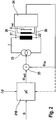
- the microcontroller system 218 in FIG Fig. 2 performs all the control tasks of the braking device and is within ECU 7 ( Fig. 1 ) arranged.
- current source 23 this controls the coil of the solenoid-operated valve 21 at.
- current source 3 the coil current I can be individually set and pulse width modulated for each valve.
- a wire loop or auxiliary coil 22 is provided, whose terminals are connected to measuring device 24.
- the auxiliary coil is arranged to detect the effective magnetic flux through the yoke and armature of the coil.
- Measuring device 24 includes a circuit with which the voltage applied to the measuring coil or wire loop induction voltage U ind can be measured.
- the tap of the induced voltage can also be carried out directly on the valve coil, as shown by dashed lines 26.
- a signal ⁇ is available via the magnetic flux, which is proportional to the integral of the induced voltage U ind (t).
- the signal generated by the tap means 22, 24 over time to determine a magnitude which is proportional to the magnetic flux or the magnetic force. This can then be concluded taking into account the spring force of the valve on the hydraulic force, from which then the differential pressure can be determined on the valve. Taking into account the production-dependent valve properties, the admission pressure for the purpose of regulating the overflow pressure can be measured directly in this way.
Description
- Die Erfindung betrifft ein Verfahren gemäß Oberbegriff von Anspruch 1 sowie dessen Verwendung.
- Aus der
DE 103 41 027 A1 ist ein Verfahren zur Längsregelung (ACC) bekannt, welches in bzw. mit einem verbreitet eingesetzten zweikreisigen ABS/ESP-Kraftfahrzeugbremsensteuergerät mit Pumpe durchführbar ist. Zur Dosierung des hydraulischen Bremsdrucks wird ein analog regelndes, elektrisch ansteuerbares hydraulisches Trennventil eingesetzt, wobei dieses im Gegensatz zu einer Regelung mit einem analog angesteuerten Einlassventil eine bremskreisübergreifende Druckregelung zulässt. Die zur Druckregelung eingesetzten Hydraulikventile sind in der Regel herkömmliche elektromagnetisch betriebene Sitzventile, welche zum Schalten konstruiert sind. Werden diese allerdings mittels eines pulsweitenmodulierten Stroms (PWM) in der Weise angesteuert, dass der Ventilstößel eine Schwimmstellung einnimmt, ist auch ein Analogregelung des Durchflusses möglich. Hierzu muss aber die Stromregelung sehr genau und reproduzierbar durchgeführt werden. Dies ist in der Regel dann ohne größere Probleme möglich, wenn der einzuregelnde Druck über einen Drucksensor in Verbindung mit einer Regelschleife eingeregelt werden kann. Erheblich schwieriger ist es, ein entsprechendes Analogregelverfahren ohne einen Drucksensor im zu regelnden Druckkreis vorzunehmen. In diesem Fall wird häufig auf gespeicherte Ventilkennlinien zurückgegriffen, welche in Verbindung mit an sich bekannten Regelverfahren eine Druckeinstellung im Rad ohne zusätzliche Raddrucksensoren erlauben. Die vorstehend erwähnte Ventilkennlinie erlaubt also eine Druckeinstellung durch das Ventil nach Maßgabe einer dem Regler als Eingangsgröße vorliegenden Druckanforderung. - Die
WO 2007/025951 (P 11192) beschreibt ein Verfahren zur Bestimmung eines zwischen einem Hauptbremszylinder und einem Einlassventil eines Radbremszylinders einer Kraftfahrzeug-Bremsanlage herrschenden Vordrucks, welches den Vordruck unter Berücksichtigung des Verlaufs einer Nachlaufspannung eines getaktet betriebenen Motors einer Pumpe, welche zur Rückförderung von Bremsflüssigkeit aus einem Niederdruckspeicher in den Hauptbremszylinder verwendet wird, bestimmt. Zur Bestimmung des Vordrucks werden elektrische Kenngrößen des Spannungsverlaufs gemessen und jeweils zur Bestimmung eines Vordruckwertes herangezogen. Mit dieser Methode kann aber immer noch nicht mit ausreichender Genauigkeit der durch die Pumpe hervorgerufene Druck bestimmt werden. - Aus der
WO 2005/012056 A1 (P 10991) ist ein Verfahren zur Bestimmung des Drucks eines Fluids oder des an einem elektromagnetisch ansteuerbaren Regelventil vorliegenden Differenzdrucks bekannt, bei dem zur Druckmessung das Druckregelventil herangezogen wird. Das Druckregelventil umfasst die üblichen Komponenten eines elektrohydraulischen Druckregelventils, wie Erregerspule, Ventilstößel, Ventildome etc.. Die Druckmessung erfolgt über einen elektronischen Regelkreis, der die Position des Ventilbetätigungseinrichtung oder die magnetische Kraft einregeregelt. Die zur Regelung verwendete Größe, die als Istwert herangezogen wird, repräsentiert die auf den Ventilstößel wirkende hydraulische Kraft. Die Messung dieser Kraft erfolgt durch Messung der entsprechenden magnetischen Kraft, welche sich aus der im Bereich der Erregerspule induzierten Spannung ermitteln lässt. - Die Aufgabe der vorliegenden Erfindung besteht nun darin, eine elektronische Druckregelvorrichtung mit Funktionskomponenten für einen aktiven Druckaufbau besonders ökonomisch und geräuscharm zu betreiben.
- Diese Aufgabe wird erfindungsgemäß gelöst durch das Verfahren gemäß Anspruch 1.
- Der Erfindung liegt der Gedanke zu Grunde, bei der analogisierten Ventilregelung einen möglichst optimalen Vordruck bei der Ventilregelung einzustellen. In der Regel ist der Vordruck um ein bestimmtes Maß höher, als der Druck an der Auslassseite des Ventils. Im beispielhaften Falle einer Regelung mit einem Trennventil wird der Vordruck auch als sogenannter Überstömdruck bezeichnet. Der Überströmdruck bezeichnet den Druck, der bei einem aktiven Druckaufbau durch ein Motorpumpenaggregat vor dem Trennventil auf der dem Pumpenausgang und den Radeinlassventilen vorgeschalteten Seite hervorgerufen wird, zum Beispiel während einer Abstandsregelung (ACC). Der Vordruck oder Überströmdruck bei einer Trennventilregelung wird also im wesentlichen durch die Drehzahl und Einschaltdauer des Pumpenmotors und der Öffnungsstellung des Trennventils bestimmt. Es wird aus Komfort-, Geräusch- und ökonomischen Gründen angestrebt, den am geregelten Ventil anliegenden Differenzdruck, insbesondere den Überströmdruck, möglichst gering zu halten. In heutigen Bremsanlagen ist dies aber auf Grund von Fertigungsstreuungen in der Kette Motor/Pumpe nicht optimal möglich, da durch die elektronische Ansteuerung immer ein ausreichender Offset für die Pumpenansteuerung vorgesehen werden muss, damit auch bei Bremsensteuergeräten mit schwächeren Motorpumpenaggregaten noch ein ausreichendes Überströmen sichergestellt ist.
- Zur Bemessung des Vordrucks wird erfindungsgemäß bevorzugt ein Sollwert für den Motor des Motorpumpenaggregats vorgegeben, wobei bei der Ermittlung des Sollwerts ein elektrisches Signal aus dem Stößelstellungsregelkreis einbezogen wird.
- Nach der Erfindnug wird der Vordruck durch elektronische Auswertung der Stößelreaktion eines Ventils eingestellt. Der Begriff "Stößelreaktion" soll neben dem Fall einer durch eine Druckänderung hervorgerufenen Stößelbewegung auch den Fall umfassen, bei dem lediglich die Ansteuerelektronik des entsprechenden Ventils auf eine Druckänderung am Ventil durch eine Stromänderung reagiert, ohne dass sich die Stößelposition merklich ändert. Es ist also auch möglich, dass sich dabei nur die Kräfteverhältnisse ändern, da beispielsweise auf Grund einer höheren Druckdifferenz ein größerer Ventilstrom eingestellt werden muss. Eine Auswertung der Stößelreaktion ist bevorzugt mit dem oben beschriebenen Regelkreis dann möglich, wenn sich der Stößel im oder in der Nähe eines Kräftegleichgewichts zwischen der Magnetkraft (abzüglich oder zuzüglich der Ventilfederkraft) und der hydraulischen Kraft befindet. Liegen die Kräfte weit auseinander, kann der Stößel nicht auf eine Druckänderung reagieren.
- Die Stößelreaktion kann an dem Ventil, an dem der Vordruck bestimmt werden soll, oder an einem weiteren Ventil beobachtet werden. Prinzipiell kann jedes elektromagnetisch angesteuerte Hydraulikventil für diesen Zweck herangezogen werden, sofern dieses mit der Ausgangsseite des Motorpumpenaggregats über Druckleitung verbunden ist. Die Stößelreaktion, insbesondere die Stößelstellung oder die hydraulische Kraft, wird bevorzugt mittels eines elektrischen Stößelstellungsregelkreises bestimmt.
- Vorzugsweise wird auf Grundlage der Stößelreaktion mittels des sogenannten TPM-Verfahrens ein Messung des Differenzdrucks am Messventil durchgeführt. Das TPM-Verfahren (Tapet Position Monitoring) ermöglicht, die Stößelstellung in einem elektromagnetisch angesteuerten Ventil oder die auf den Stößel des Ventils wirkende Kraft mittels einer Regelung einzustellen und insbesondere zu messen.
- Die Erfindung betrifft auch eine elektronisch gesteuerte Kraftfahrzeugbremsdruckregelvorrichtung gemäß Anspruch 10.
- Weitere bevorzugte Ausführungsformen ergeben sich aus den Unteransprüchen und der nachfolgenden Beschreibung eines Ausführungsbeispiels an Hand von Figuren.
- Es zeigen
- Fig. 1
- eine schematische Darstellung einer Bremsvorrichtung für ABS- und ESP-Regelvorgänge und
- Fig. 2
- eine schematische Darstellung eines Regelkreises zum Regeln des Magnetflusses mit Messspule.
- In
Fig. 1 ist Tandemhauptzylinder 5 mit Hydraulikeinheit 6 (HCU) eines elektronischen Kraftfahrzeugbremssystems verbunden. Elektronikeinheit 7 (ECU) umfasst ein Mikroprozessor/controllersystem, mit dem die im Ventilblock enthaltenen Aktuatoren und Sensoren elektronisch gesteuert bzw. ausgemessen werden können. Hydraulikeinheit 6 ist in zwei Bremskreise I und II aufgeteilt. Ferner umfasst jeder der Bremskreise je zwei Raddruckkreise (A, B bzw. C, D) mit jeweils einem Einlass- 3 bzw. 3' und einem Auslassventil 4 bzw. 4'. Die Elektronik der ECU 7 umfasst einen mehrkanaligen Stromregler, welcher eine unabhängige Regelung der Ströme durch die Spulen der Trennventile 2, 2' und der Einlassventile 3, 3' erlaubt. Bezugszeichen 8 bzw. 8' bezeichnen stromlos geschlossene elektronische Umschaltventile. In der zu Hauptzylinder 5 führenden Hydraulikleitung 8 befindet sich ein Eingangsdrucksensor 9. Das dargestellte Bremssystem umfasst in den Raddruckkreisen selbst keine weiteren Drucksensoren. Motor-Pumpenaggregat 1 bzw. 1' dient dem aktiven Druckaufbau bei ACC-, TCS- und ESP-Regelungen sowie zur Rückförderung des an den Auslassventilen ausgetretenen Druckmittels, welches sich in Niederdruckspeicher 16 bzw. 16' befindet. Wenn Pumpe 1 angeschaltet ist, fördert diese Druckvolumen in Richtung von Leitung 13, so dass sich der Vordruck erhöht. Auf Grund des Aufbaus der Pumpe pulsiert der Druck am Ausgang der Pumpe in einem vom Aufbau der hydraulischen Komponenten abhängigen Druckbereich. - Bei der Durchführung der Vordruckbemessung wird Pumpe 1 zur Erzeugung von Druckpulsationen zunächst mit einem geeigneten PWM-Strom angesteuert. Am analogisiert betriebenen Einlassventil 3 ergibt sich durch die während der Förderung von Druckmittel mittels der Hydraulikpumpe auftretenden Druckpulsationen ein zumindest qualitativ messbarer Differenzdruck. Eine qantitative Druckbestimmung ist mit dem TPM-Verfahren prinzipiell ebenfalls möglich und daher alternativ bevorzugt. Der PWM-Strom für die Pumpe wird über einen Regler eingestellt, der als Istwert den gemessenen Differenzdruck nutzt oder diesen zumindest in die Regelung miteinbezieht.
- Das Mikrocontrollersystem 218 in
Fig. 2 führt alle Regelungsaufgaben der Bremsvorrichtung durch und ist innerhalb von ECU 7 (Fig. 1 ) angeordnet. Über Stromquelle 23 steuert diese die Spule des elektromagnetisch betriebenen Ventils 21 an. Der Einfachheit halber ist nur eine Ventil-Verstärker Kombination dargestellt. Mit Stromquelle 3 kann der Spulenstrom I individuell für jedes Ventil pulsweitenmoduliert eingestellt und auch gemessen werden. In obiger Bremsvorrichtung sind für jedes Ventil entsprechende Ventiltreiber vorgesehen, die mittels individuell ansteuerbarer PWM-Treiberstufen realisiert sind. Im Bereich des Spulenmagnetfelds ist eine Drahtschleife oder Hilfsspule 22 vorgesehen, deren Anschlussklemmen mit Messeinrichtung 24 verbunden ist. Die Hilfsspule ist insbesondere so angeordnet, dass sie den wirksamen magnetischen Fluss durch Joch und Anker der Spule erfasst. Messeinrichtung 24 enthält eine Schaltung, mit der die an der Messpule bzw. Drahtscheife anliegende Induktionsspannung Uind gemessen werden kann. Prinzipiell kann der Abgriff der induzierten Spannung auch direkt an der Ventilspule erfolgen, wie dies durch gestrichelte Leitungen 26 gezeigt ist. Am Ausgang von Messeinrichtung 4 steht ein Signal Φist über den magnetischen Fluss zur Verfügung, welches proportional zum Integral über die induzierte Spannung Uind(t) ist. - Bei einer von außen oder durch den Verstärker hervorgerufenen Bewegung des Ventilstößels ergibt sich eine Änderung des magnetischen Flusses Φ in Ventilspule 21, welche durch die Messeinrichtung 24 über Induktionsspannung Uind gemessen werden kann. Messeinrichtung 24 bildet das zeitliche Integral über den Verlauf der induzierten Spannung Uind und führt das integrierte Signal dem Mikrocontroller 218 oder einem zusätzlichen Regler 25 zu. Durch die Rückführung des Signals der Messeinrichtung in den Mikrocontroller lässt sich demzufolge eine Stößelhubregelung oder eine Stößelkraftregelung realisieren.
- Gemäß einer bevorzugten Ausführungsform ist vorgesehen, das durch die Abgriffeinrichtung 22, 24 erzeugte Signal über die Zeit aufzuintegrieren, um eine Größe zu ermitteln, die zum magnetischen Fluss oder der magnetischen Kraft proportional ist. Damit kann dann unter Berücksichtigung der Federkraft des Ventils auf die hydraulische Kraft geschlossen werden, aus der sich dann der Differenzdruck am Ventil ermitteln lässt. Unter Berücksichtigung der fertigungsabhängigen Ventileigenschafen lässt sich auf diese Weise der Vordruck zum Zwecke des Einregelns des Überströmdrucks direkt messen.
Claims (9)
- Verfahren zum Bemessen des Vordrucks an einem ersten analogisierten, elektromagnetisch angesteuerten Hydraulikventil (2, 2') zum feinfühligen Regeln des Drucks in einem Druckkreis (13), bei dem der Vordruck am ersten Ventil über die Förderleistung eines Motorpumpenaggregats (1, 1') einstellbar ist, das mit dem ersten Ventil über eine pumpenausgangsseitige Druckleitung (13) verbunden ist, wobei zur Bemessung des Vordrucks ein Sollwert für den Motor des Motorpumpenaggregats vorgegeben wird, insbesondere in einer hydraulischen Kraftfahrzeugbremsanlage, dadurch gekennzeichnet, dass der Vordruck durch elektronische Auswertung der Stößelreaktion des ersten Ventils (2, 2') oder eines weiteren ebenfalls elektromagnetisch angesteuerten und mit der pumpenausgangsseitigen Druckleitung (13) verbunden Hydraulikventils (3,3') eingestellt wird, wobei die Stößelreaktion mittels eines elektrischen Stößelstellungsregelkreises bestimmt wird und wobei bei der Ermittlung des Sollwerts ein elektrisches Signal aus dem Stößelstellungsregelkreis einbezogen wird.
- Verfahren nach Anspruch 1, dadurch gekennzeichnet, dass die hydraulische Bremsanlage mehrere jeweils den Raddruckkreisen zugeordnete Ein- (3, 3') und Auslassventile (4, 4') umfasst und dass das erste oder das weitere Ventil ein analog ansteuerbares Trennventil (2, 2') zum Abtrennen der Bremsbetätigungseinheit (5) von den Einlassventilen der Radbremskreise ist.
- Verfahren nach Anspruch 2, dadurch gekennzeichnet, dass das erste oder das weitere Ventil mit einer elektrischen Abgriffeinrichtung (22, 24) versehen ist, welches eine elektronische Bestimmung der Stößelstellung erlaubt.
- Verfahren nach mindestens einem der Ansprüche 1 bis 3, dadurch gekennzeichnet, dass die Stößelstellung oder die hydraulische Kraft mittels eines elektrischen Stößelstellungsregelkreises bestimmt wird.
- Verfahren nach Anspruch 3 oder 4, dadurch gekennzeichnet, dass durch die Abgriffeinrichtung die Induktionsspannung oder der Induktionsstrom bei einer Stößelbewegung bestimmt wird, entweder durch Abgriff an der Ventilspule selbst oder mit Hilfe einer zusätzlichen
Drahtschleife oder -spule im Bereich des Magnetkreises des Magnetventils. - Verfahren nach mindestens einem der Ansprüche 1 bis 5, dadurch gekennzeichnet, dass das erste oder weitere Ventil durch eine geeignete Stromeinstellung in oder in die Nähe eines Kräftegleichgewichts eingestellt wird, so dass dieses für Druckänderungen empfindlich ist.
- Verfahren nach mindestens einem der Ansprüche 1 bis 6, dadurch gekennzeichnet, dass das erste oder weitere Ventil zur Bestimmung des am Ventil anliegenden Differenzdruck herangezogen wird.
- Verfahren nach mindestens einem der Ansprüche 3 bis 7, dadurch gekennzeichnet, dass das durch die Abgriffeinrichtung (22, 24) erzeugte Signal über die Zeit aufintegriert wird, um eine Größe zu ermitteln, die zum magnetischen Fluss oder der magnetischen Kraft proportional ist, und damit unter Berücksichtigung der Federkraft des Ventils auf die hydraulische Kraft geschlossen wird, aus der sich dann der Differenzdruck am Ventil ermitteln lässt.
- Elektronisch gesteuerte Kraftfahrzeugbremsdruckregelvorrichtung mit zumindest einem ABS-Regler, insbesondere auch einem ESP-Regler, umfassend ein Druckerzeugungsmittel (5) mit dem vom Fahrerwunsch abhängig Druckmittel über Druckleitungen in ein Hydraulikaggregat (6) eingesteuert werden kann, mit Trennventilen (2, 2') zum Abtrennen der Raddruckkreise (A....D) vom Druckerzeugungsmittel (5) sowie Einlassventilen (3, 3'), welche mit den Trennventilen und den Raddruckkreisen hydraulisch verbunden sind, umfassend weiterhin Mittel für einen aktiven Druckaufbau (8, 8', 1, 1'), dadurch gekennzeichnet, dass die elektronische Steuerung der Vorrichtung so eingerichtet ist, dass diese bei Bedarf ein Verfahren gemäß mindestens einem der Ansprüche 1 bis 8 durchführen kann.
Applications Claiming Priority (2)
| Application Number | Priority Date | Filing Date | Title |
|---|---|---|---|
| DE102007032950A DE102007032950A1 (de) | 2007-07-14 | 2007-07-14 | Verfahren zum Bemessen des Vordrucks an einem analogisierten, elektromagnetisch angesteuerten Hydraulikventil |
| PCT/EP2008/055938 WO2009010319A2 (de) | 2007-07-14 | 2008-05-15 | Verfahren zum bemessen des vordrucks an einem analogisierten, elektromagnetisch angesteuerten hydraulikventil |
Publications (2)
| Publication Number | Publication Date |
|---|---|
| EP2170667A2 EP2170667A2 (de) | 2010-04-07 |
| EP2170667B1 true EP2170667B1 (de) | 2012-04-25 |
Family
ID=40121544
Family Applications (1)
| Application Number | Title | Priority Date | Filing Date |
|---|---|---|---|
| EP08750294A Not-in-force EP2170667B1 (de) | 2007-07-14 | 2008-05-15 | Verfahren zum bemessen des vordrucks an einem analogisierten, elektromagnetisch angesteuerten hydraulikventil |
Country Status (5)
| Country | Link |
|---|---|
| US (1) | US8789897B2 (de) |
| EP (1) | EP2170667B1 (de) |
| AT (1) | ATE554979T1 (de) |
| DE (1) | DE102007032950A1 (de) |
| WO (1) | WO2009010319A2 (de) |
Families Citing this family (4)
| Publication number | Priority date | Publication date | Assignee | Title |
|---|---|---|---|---|
| DE102010028083A1 (de) * | 2009-04-23 | 2010-11-11 | Continental Teves Ag & Co. Ohg | Verfahren zur Kalibrierung eines Pumpenmotors in einer Druckregelanlage |
| DE102012224030A1 (de) * | 2012-12-20 | 2014-06-26 | Continental Teves Ag & Co. Ohg | Verfahren zur beschleunigten Ermittlung eines Korrekturwerts für eine drucksensorlose Bestimmung eines hydraulischen Drucks in einem hydraulischen Bremssystem sowie hydraulisches Bremssystem und Verwendung des Bremssystems |
| DE102015221228A1 (de) * | 2015-01-21 | 2016-07-21 | Continental Teves Ag & Co. Ohg | Bremsensteuervorrichtung für eine hydraulische Kraftfahrzeug-Bremsanlage sowie Bremsanlage |
| CN115493740B (zh) * | 2022-11-14 | 2023-02-28 | 长江勘测规划设计研究有限责任公司 | 利用机器视觉测量水轮机内部流道压力脉动的方法及系统 |
Family Cites Families (23)
| Publication number | Priority date | Publication date | Assignee | Title |
|---|---|---|---|---|
| DE3511975A1 (de) * | 1985-04-02 | 1986-10-09 | Daimler-Benz Ag, 7000 Stuttgart | Hydraulischer bremskraftverstaerker |
| DE3730523A1 (de) * | 1987-09-11 | 1989-03-30 | Bosch Gmbh Robert | Verfahren und einrichtung zur detektion der schaltzeiten von magnetventilen |
| US5628550A (en) * | 1991-10-18 | 1997-05-13 | Itt Automotive Europe Gmbh | Anti-lock hydraulic brake system |
| DE4303206C2 (de) * | 1993-02-04 | 2002-08-08 | Continental Teves Ag & Co Ohg | Verfahren und Schaltungsanordnung zum Bestimmen der Pedalkraft als Regelgröße für eine Bremsanlage mit Blockierschutzregelung |
| DE4438336A1 (de) * | 1994-10-27 | 1996-05-02 | Bosch Gmbh Robert | Magnetventil mit Druckbegrenzung für schlupfgeregelte Kraftfahrzeug-Bremsanlagen |
| DE19508329A1 (de) * | 1995-03-09 | 1996-09-12 | Teves Gmbh Alfred | Bremsdruckregelanlage |
| GB9515542D0 (en) * | 1995-07-28 | 1995-09-27 | Lucas Ind Plc | Accumulator pressure control in vehicle brake systems |
| DE19528697A1 (de) * | 1995-08-04 | 1997-02-06 | Bosch Gmbh Robert | Verfahren und Vorrichtung zur Ermittlung einer Druckgröße |
| US6293237B1 (en) * | 1997-12-11 | 2001-09-25 | Diesel Engine Retarders, Inc. | Variable lost motion valve actuator and method |
| JP2002533263A (ja) * | 1998-12-28 | 2002-10-08 | ロベルト・ボッシュ・ゲゼルシャフト・ミト・ベシュレンクテル・ハフツング | ブレーキ装置内の圧力の決定方法および装置 |
| DE19946777B4 (de) * | 1999-09-29 | 2008-01-10 | Robert Bosch Gmbh | Verfahren und Vorrichtung zur Abschätzung eines Vordrucks bei einer Kraftfahrzeug-Bremsanlage |
| EP1132274B1 (de) * | 2000-02-26 | 2004-04-07 | WABCO GmbH & CO. OHG | Bremsdruckmodulator für elektronische Bremsanlage |
| WO2001098124A1 (de) * | 2000-06-20 | 2001-12-27 | Continental Teves Ag & Co. Ohg | Verfahren und regelsystem zur ansteuerung eines elektronisch regelbaren bremsbetätigungssystems |
| EP1167148B1 (de) * | 2000-07-01 | 2008-02-06 | Robert Bosch GmbH | Verfahren und Gerät zur Berechnung der Ansteuerung einer hydraulischen FDR/ESP Unterbaugruppe zur Reduzierung hydraulischer Geräusche |
| EP1478557B1 (de) * | 2002-02-14 | 2015-01-28 | Continental Teves AG & Co. oHG | Verfahren zum einregeln eines vorgegebenen veränderlichen bremsdruckes |
| DE10341027A1 (de) | 2002-09-06 | 2004-03-25 | Continental Teves Ag & Co. Ohg | Verfahren und Vorrichtung zur Regelung einer Bremsanlage für Kraftfahrzeuge |
| CA2634470C (en) * | 2003-01-24 | 2013-05-14 | Pratt & Whitney Canada Corp. | Method and system for trend detection and analysis |
| US20070158607A1 (en) * | 2003-07-31 | 2007-07-12 | Continental Teves Ag & Co. Ohg | Method for determining the drive current for an actuator |
| JP4994838B2 (ja) | 2003-07-31 | 2012-08-08 | コンティネンタル・テーベス・アクチエンゲゼルシヤフト・ウント・コンパニー・オッフェネ・ハンデルスゲゼルシヤフト | 制御装置によって油圧を測定する方法及び装置 |
| US20050067895A1 (en) * | 2003-09-25 | 2005-03-31 | Marathe Sameer S. | Apparatus and method of monitoring braking system pressure |
| DE502004004396D1 (de) * | 2003-11-26 | 2007-08-30 | Bosch Gmbh Robert | Verfahren zum ansteuern eines zweistufigen schaltventils |
| DE102005055751B4 (de) * | 2005-04-21 | 2018-09-06 | Ipgate Ag | Druckmodulatorsteuerung |
| DE102005041556A1 (de) | 2005-09-01 | 2007-03-08 | Continental Teves Ag & Co. Ohg | Verfahren zur Bestimmung eines Vordrucks in einer Kraftfahrzeug-Bremsanlage |
-
2007
- 2007-07-14 DE DE102007032950A patent/DE102007032950A1/de not_active Withdrawn
-
2008
- 2008-05-15 EP EP08750294A patent/EP2170667B1/de not_active Not-in-force
- 2008-05-15 WO PCT/EP2008/055938 patent/WO2009010319A2/de active Application Filing
- 2008-05-15 AT AT08750294T patent/ATE554979T1/de active
- 2008-05-15 US US12/668,945 patent/US8789897B2/en not_active Expired - Fee Related
Also Published As
| Publication number | Publication date |
|---|---|
| ATE554979T1 (de) | 2012-05-15 |
| US8789897B2 (en) | 2014-07-29 |
| US20100201184A1 (en) | 2010-08-12 |
| EP2170667A2 (de) | 2010-04-07 |
| DE102007032950A1 (de) | 2009-01-15 |
| WO2009010319A2 (de) | 2009-01-22 |
| WO2009010319A3 (de) | 2009-04-16 |
Similar Documents
| Publication | Publication Date | Title |
|---|---|---|
| EP1876078B1 (de) | Verfahren zum Ermitteln des Ansteuerstroms eines elektrischen Stellgeräts | |
| EP2822824B1 (de) | Verfahren zum betreiben einer bremsanlage für kraftfahrzeuge sowie bremsanlage | |
| DE19654427B4 (de) | Verfahren und Vorrichtung zur Regelung des Drucks in wenigstens einer Radbremse | |
| EP2238001B1 (de) | Verfahren zur konditionierung eines regelventils | |
| EP1478557B1 (de) | Verfahren zum einregeln eines vorgegebenen veränderlichen bremsdruckes | |
| EP2528789B1 (de) | Elektronisches steuergerät für ein bremssystem | |
| DE102007032949B4 (de) | Verfahren zur Bestimmung der Förderleistung oder der Betätigungshäufigkeit einer Fluidpumpe, insbesondere in einem elektronischen Kraftfahrzeugbremssystem | |
| DE102007010514A1 (de) | Verfahren zur Kalibrierung von analogisierten Ventilen in einer Druckregelvorrichtung | |
| DE102012205117A1 (de) | Fluiddruckverstärker und diesen aufweisende Fluiddruckbremsvorrichtung | |
| EP2170667B1 (de) | Verfahren zum bemessen des vordrucks an einem analogisierten, elektromagnetisch angesteuerten hydraulikventil | |
| EP1937529B1 (de) | Verfahren zur bestimmung des raddrucks in einem elektronisch ansteuerbaren kraftfahrzeugbremsenregelungssystem | |
| EP2739513B1 (de) | Verfahren zur optimierung der druckstellgenauigkeit | |
| DE102008036607A1 (de) | Verfahren und Vorrichtung zur hydraulischen Bremsdruckverstärkung | |
| DE19923689A1 (de) | Elektrohydraulisches Bremssystem und Verfahren zu seiner Steuerung | |
| DE102007018515B4 (de) | Vorrichtung zur Bremsdruckregelung mit Blockierschutzfunktion und weiteren Regelungen | |
| EP1651486B1 (de) | Verfahren und vorrichtung zum messen eines fluiddrucks mittels eines stellgeräts | |
| DE102007034113A1 (de) | Verfahren zur Kalibrierung einer Hydraulikpumpe | |
| DE19956553B4 (de) | Verfahren zum Abschätzen des Druckes in einem Radbremszylinder und Steuereinheit zur Durchführung des Verfahrens | |
| DE10012041B4 (de) | Verfahren zum Bestimmen von Kenngrößen | |
| DE10021436B4 (de) | Verfahren und Einrichtung zum Ermitteln einer Stellgröße eines Ventils und Verfahren und Einrichtung zum Ermitteln einer die Bewegungsgeschwindigkeit eines Aktuators eines Ventils wiedergebenden Größe | |
| DE102009034333B4 (de) | Verfahren zur Beeinflussung des Drehverhaltens einer Fluid-Pumpe in einem Kraftfahrzeugbremssystem | |
| DE102008036216B4 (de) | Druckregelverfahren für Kraftfahrzeugbrems- und Abstandsregelungssysteme | |
| DE102021211245A1 (de) | Radbremsen Differenzdruckregelung | |
| DE102007008908A1 (de) | Kraftfahrzeugbremssystem und Verfahren zur verbesserten ABS-Regelung | |
| DE102011086737A1 (de) | Verfahren zur Verbesserung einer Vordruckschätzung in einem Hydraulikstrang einer schlupfgeregelten Kraftfahrzeugbremsanlage und Hydraulikstrang einer schlupfgeregelten Kraftfahrzeugbremsanlage |
Legal Events
| Date | Code | Title | Description |
|---|---|---|---|
| PUAI | Public reference made under article 153(3) epc to a published international application that has entered the european phase |
Free format text: ORIGINAL CODE: 0009012 |
|
| 17P | Request for examination filed |
Effective date: 20100215 |
|
| AK | Designated contracting states |
Kind code of ref document: A2 Designated state(s): AT BE BG CH CY CZ DE DK EE ES FI FR GB GR HR HU IE IS IT LI LT LU LV MC MT NL NO PL PT RO SE SI SK TR |
|
| 17Q | First examination report despatched |
Effective date: 20110429 |
|
| GRAP | Despatch of communication of intention to grant a patent |
Free format text: ORIGINAL CODE: EPIDOSNIGR1 |
|
| GRAC | Information related to communication of intention to grant a patent modified |
Free format text: ORIGINAL CODE: EPIDOSCIGR1 |
|
| DAX | Request for extension of the european patent (deleted) | ||
| RAP1 | Party data changed (applicant data changed or rights of an application transferred) |
Owner name: CONTINENTAL TEVES AG & CO. OHG |
|
| GRAS | Grant fee paid |
Free format text: ORIGINAL CODE: EPIDOSNIGR3 |
|
| GRAA | (expected) grant |
Free format text: ORIGINAL CODE: 0009210 |
|
| AK | Designated contracting states |
Kind code of ref document: B1 Designated state(s): AT BE BG CH CY CZ DE DK EE ES FI FR GB GR HR HU IE IS IT LI LT LU LV MC MT NL NO PL PT RO SE SI SK TR |
|
| REG | Reference to a national code |
Ref country code: GB Ref legal event code: FG4D Free format text: NOT ENGLISH |
|
| REG | Reference to a national code |
Ref country code: CH Ref legal event code: EP |
|
| REG | Reference to a national code |
Ref country code: AT Ref legal event code: REF Ref document number: 554979 Country of ref document: AT Kind code of ref document: T Effective date: 20120515 |
|
| REG | Reference to a national code |
Ref country code: IE Ref legal event code: FG4D Free format text: LANGUAGE OF EP DOCUMENT: GERMAN |
|
| REG | Reference to a national code |
Ref country code: DE Ref legal event code: R096 Ref document number: 502008007062 Country of ref document: DE Effective date: 20120621 |
|
| REG | Reference to a national code |
Ref country code: NL Ref legal event code: VDEP Effective date: 20120425 |
|
| LTIE | Lt: invalidation of european patent or patent extension |
Effective date: 20120425 |
|
| PG25 | Lapsed in a contracting state [announced via postgrant information from national office to epo] |
Ref country code: PL Free format text: LAPSE BECAUSE OF FAILURE TO SUBMIT A TRANSLATION OF THE DESCRIPTION OR TO PAY THE FEE WITHIN THE PRESCRIBED TIME-LIMIT Effective date: 20120425 Ref country code: IS Free format text: LAPSE BECAUSE OF FAILURE TO SUBMIT A TRANSLATION OF THE DESCRIPTION OR TO PAY THE FEE WITHIN THE PRESCRIBED TIME-LIMIT Effective date: 20120825 Ref country code: NO Free format text: LAPSE BECAUSE OF FAILURE TO SUBMIT A TRANSLATION OF THE DESCRIPTION OR TO PAY THE FEE WITHIN THE PRESCRIBED TIME-LIMIT Effective date: 20120725 Ref country code: FI Free format text: LAPSE BECAUSE OF FAILURE TO SUBMIT A TRANSLATION OF THE DESCRIPTION OR TO PAY THE FEE WITHIN THE PRESCRIBED TIME-LIMIT Effective date: 20120425 Ref country code: LT Free format text: LAPSE BECAUSE OF FAILURE TO SUBMIT A TRANSLATION OF THE DESCRIPTION OR TO PAY THE FEE WITHIN THE PRESCRIBED TIME-LIMIT Effective date: 20120425 Ref country code: CY Free format text: LAPSE BECAUSE OF FAILURE TO SUBMIT A TRANSLATION OF THE DESCRIPTION OR TO PAY THE FEE WITHIN THE PRESCRIBED TIME-LIMIT Effective date: 20120425 Ref country code: SE Free format text: LAPSE BECAUSE OF FAILURE TO SUBMIT A TRANSLATION OF THE DESCRIPTION OR TO PAY THE FEE WITHIN THE PRESCRIBED TIME-LIMIT Effective date: 20120425 |
|
| BERE | Be: lapsed |
Owner name: CONTINENTAL TEVES A.G. & CO. OHG Effective date: 20120531 |
|
| PG25 | Lapsed in a contracting state [announced via postgrant information from national office to epo] |
Ref country code: HR Free format text: LAPSE BECAUSE OF FAILURE TO SUBMIT A TRANSLATION OF THE DESCRIPTION OR TO PAY THE FEE WITHIN THE PRESCRIBED TIME-LIMIT Effective date: 20120425 Ref country code: SI Free format text: LAPSE BECAUSE OF FAILURE TO SUBMIT A TRANSLATION OF THE DESCRIPTION OR TO PAY THE FEE WITHIN THE PRESCRIBED TIME-LIMIT Effective date: 20120425 Ref country code: PT Free format text: LAPSE BECAUSE OF FAILURE TO SUBMIT A TRANSLATION OF THE DESCRIPTION OR TO PAY THE FEE WITHIN THE PRESCRIBED TIME-LIMIT Effective date: 20120827 Ref country code: GR Free format text: LAPSE BECAUSE OF FAILURE TO SUBMIT A TRANSLATION OF THE DESCRIPTION OR TO PAY THE FEE WITHIN THE PRESCRIBED TIME-LIMIT Effective date: 20120726 Ref country code: LV Free format text: LAPSE BECAUSE OF FAILURE TO SUBMIT A TRANSLATION OF THE DESCRIPTION OR TO PAY THE FEE WITHIN THE PRESCRIBED TIME-LIMIT Effective date: 20120425 |
|
| PG25 | Lapsed in a contracting state [announced via postgrant information from national office to epo] |
Ref country code: MC Free format text: LAPSE BECAUSE OF NON-PAYMENT OF DUE FEES Effective date: 20120531 |
|
| REG | Reference to a national code |
Ref country code: CH Ref legal event code: PL |
|
| PG25 | Lapsed in a contracting state [announced via postgrant information from national office to epo] |
Ref country code: CZ Free format text: LAPSE BECAUSE OF FAILURE TO SUBMIT A TRANSLATION OF THE DESCRIPTION OR TO PAY THE FEE WITHIN THE PRESCRIBED TIME-LIMIT Effective date: 20120425 Ref country code: SK Free format text: LAPSE BECAUSE OF FAILURE TO SUBMIT A TRANSLATION OF THE DESCRIPTION OR TO PAY THE FEE WITHIN THE PRESCRIBED TIME-LIMIT Effective date: 20120425 Ref country code: CH Free format text: LAPSE BECAUSE OF NON-PAYMENT OF DUE FEES Effective date: 20120531 Ref country code: DK Free format text: LAPSE BECAUSE OF FAILURE TO SUBMIT A TRANSLATION OF THE DESCRIPTION OR TO PAY THE FEE WITHIN THE PRESCRIBED TIME-LIMIT Effective date: 20120425 Ref country code: RO Free format text: LAPSE BECAUSE OF FAILURE TO SUBMIT A TRANSLATION OF THE DESCRIPTION OR TO PAY THE FEE WITHIN THE PRESCRIBED TIME-LIMIT Effective date: 20120425 Ref country code: LI Free format text: LAPSE BECAUSE OF NON-PAYMENT OF DUE FEES Effective date: 20120531 Ref country code: NL Free format text: LAPSE BECAUSE OF FAILURE TO SUBMIT A TRANSLATION OF THE DESCRIPTION OR TO PAY THE FEE WITHIN THE PRESCRIBED TIME-LIMIT Effective date: 20120425 Ref country code: EE Free format text: LAPSE BECAUSE OF FAILURE TO SUBMIT A TRANSLATION OF THE DESCRIPTION OR TO PAY THE FEE WITHIN THE PRESCRIBED TIME-LIMIT Effective date: 20120425 |
|
| REG | Reference to a national code |
Ref country code: IE Ref legal event code: MM4A |
|
| PG25 | Lapsed in a contracting state [announced via postgrant information from national office to epo] |
Ref country code: IT Free format text: LAPSE BECAUSE OF FAILURE TO SUBMIT A TRANSLATION OF THE DESCRIPTION OR TO PAY THE FEE WITHIN THE PRESCRIBED TIME-LIMIT Effective date: 20120425 Ref country code: BE Free format text: LAPSE BECAUSE OF NON-PAYMENT OF DUE FEES Effective date: 20120531 |
|
| PLBE | No opposition filed within time limit |
Free format text: ORIGINAL CODE: 0009261 |
|
| REG | Reference to a national code |
Ref country code: FR Ref legal event code: ST Effective date: 20130131 |
|
| STAA | Information on the status of an ep patent application or granted ep patent |
Free format text: STATUS: NO OPPOSITION FILED WITHIN TIME LIMIT |
|
| GBPC | Gb: european patent ceased through non-payment of renewal fee |
Effective date: 20120725 |
|
| 26N | No opposition filed |
Effective date: 20130128 |
|
| PG25 | Lapsed in a contracting state [announced via postgrant information from national office to epo] |
Ref country code: IE Free format text: LAPSE BECAUSE OF NON-PAYMENT OF DUE FEES Effective date: 20120515 Ref country code: ES Free format text: LAPSE BECAUSE OF FAILURE TO SUBMIT A TRANSLATION OF THE DESCRIPTION OR TO PAY THE FEE WITHIN THE PRESCRIBED TIME-LIMIT Effective date: 20120805 Ref country code: GB Free format text: LAPSE BECAUSE OF NON-PAYMENT OF DUE FEES Effective date: 20120725 Ref country code: FR Free format text: LAPSE BECAUSE OF NON-PAYMENT OF DUE FEES Effective date: 20120625 |
|
| REG | Reference to a national code |
Ref country code: DE Ref legal event code: R097 Ref document number: 502008007062 Country of ref document: DE Effective date: 20130128 |
|
| PG25 | Lapsed in a contracting state [announced via postgrant information from national office to epo] |
Ref country code: BG Free format text: LAPSE BECAUSE OF FAILURE TO SUBMIT A TRANSLATION OF THE DESCRIPTION OR TO PAY THE FEE WITHIN THE PRESCRIBED TIME-LIMIT Effective date: 20120725 Ref country code: MT Free format text: LAPSE BECAUSE OF FAILURE TO SUBMIT A TRANSLATION OF THE DESCRIPTION OR TO PAY THE FEE WITHIN THE PRESCRIBED TIME-LIMIT Effective date: 20120425 |
|
| PG25 | Lapsed in a contracting state [announced via postgrant information from national office to epo] |
Ref country code: TR Free format text: LAPSE BECAUSE OF FAILURE TO SUBMIT A TRANSLATION OF THE DESCRIPTION OR TO PAY THE FEE WITHIN THE PRESCRIBED TIME-LIMIT Effective date: 20120425 |
|
| PG25 | Lapsed in a contracting state [announced via postgrant information from national office to epo] |
Ref country code: LU Free format text: LAPSE BECAUSE OF NON-PAYMENT OF DUE FEES Effective date: 20120515 |
|
| REG | Reference to a national code |
Ref country code: AT Ref legal event code: MM01 Ref document number: 554979 Country of ref document: AT Kind code of ref document: T Effective date: 20130515 |
|
| PG25 | Lapsed in a contracting state [announced via postgrant information from national office to epo] |
Ref country code: HU Free format text: LAPSE BECAUSE OF FAILURE TO SUBMIT A TRANSLATION OF THE DESCRIPTION OR TO PAY THE FEE WITHIN THE PRESCRIBED TIME-LIMIT Effective date: 20080515 |
|
| PG25 | Lapsed in a contracting state [announced via postgrant information from national office to epo] |
Ref country code: AT Free format text: LAPSE BECAUSE OF NON-PAYMENT OF DUE FEES Effective date: 20130515 |
|
| REG | Reference to a national code |
Ref country code: DE Ref legal event code: R084 Ref document number: 502008007062 Country of ref document: DE |
|
| PGFP | Annual fee paid to national office [announced via postgrant information from national office to epo] |
Ref country code: DE Payment date: 20200531 Year of fee payment: 13 |
|
| REG | Reference to a national code |
Ref country code: DE Ref legal event code: R119 Ref document number: 502008007062 Country of ref document: DE |
|
| PG25 | Lapsed in a contracting state [announced via postgrant information from national office to epo] |
Ref country code: DE Free format text: LAPSE BECAUSE OF NON-PAYMENT OF DUE FEES Effective date: 20211201 |