EP2170210B1 - Selbstligierende orthodontische Klammmer - Google Patents
Selbstligierende orthodontische Klammmer Download PDFInfo
- Publication number
- EP2170210B1 EP2170210B1 EP08772143.7A EP08772143A EP2170210B1 EP 2170210 B1 EP2170210 B1 EP 2170210B1 EP 08772143 A EP08772143 A EP 08772143A EP 2170210 B1 EP2170210 B1 EP 2170210B1
- Authority
- EP
- European Patent Office
- Prior art keywords
- bracket
- ligating slide
- slot
- pin
- bracket body
- Prior art date
- Legal status (The legal status is an assumption and is not a legal conclusion. Google has not performed a legal analysis and makes no representation as to the accuracy of the status listed.)
- Active
Links
Images


Classifications
-
- A—HUMAN NECESSITIES
- A61—MEDICAL OR VETERINARY SCIENCE; HYGIENE
- A61C—DENTISTRY; APPARATUS OR METHODS FOR ORAL OR DENTAL HYGIENE
- A61C7/00—Orthodontics, i.e. obtaining or maintaining the desired position of teeth, e.g. by straightening, evening, regulating, separating, or by correcting malocclusions
- A61C7/12—Brackets; Arch wires; Combinations thereof; Accessories therefor
- A61C7/28—Securing arch wire to bracket
- A61C7/287—Sliding locks
-
- A—HUMAN NECESSITIES
- A61—MEDICAL OR VETERINARY SCIENCE; HYGIENE
- A61C—DENTISTRY; APPARATUS OR METHODS FOR ORAL OR DENTAL HYGIENE
- A61C7/00—Orthodontics, i.e. obtaining or maintaining the desired position of teeth, e.g. by straightening, evening, regulating, separating, or by correcting malocclusions
- A61C7/12—Brackets; Arch wires; Combinations thereof; Accessories therefor
- A61C7/14—Brackets; Fixing brackets to teeth
- A61C7/146—Positioning or placement of brackets; Tools therefor
Definitions
- the invention relates generally to orthodontic brackets and, more particularly, to self-ligating orthodontic brackets having movable closure members such as slides or latches and related tools for deploying the same.
- Orthodontic brackets represent a principal component of all corrective orthodontic treatments devoted to improving a patient's occlusion.
- an orthodontist or an assistant affixes brackets to the patient's teeth and engages an archwire into a slot of each bracket.
- the archwire applies corrective forces that coerce the teeth to move into correct positions.
- Traditional ligatures such as small elastomeric O-rings or fine metal wires, are employed to retain the archwire within each bracket slot. Due to difficulties encountered in applying an individual ligature to each bracket, self-ligating orthodontic brackets have been developed that eliminate the need for ligatures by relying on a movable portion or member, such as a latch or slide, for retaining the archwire within the bracket slot.
- EP 0623320 discloses an orthodontic bracket for coupling an archwire with a tooth, comprising an orthodontic bracket for coupling an archwire with a tooth, comprising a bracket body configured to be mounted to the tooth, the bracket body including an archwire slot adapted to receive the archwire therein a movable member engaged with the bracket body and movable relative thereto between an opened position in which the archwire is insertable into the archwire slot, and a closed position in which the movable member retains the archwire in the archwire slot; and a securing mechanism configured to secure the movable member in at least the closed position, the securing mechanism including a projecting portion in one of the bracket body and the movable member, and a receiving portion in the other of the bracket body and the movable member, wherein at least a portion of the projecting portion is capable of moving between an expanded state and a contracted state, the projecting portion defining a first cross dimension in the expanded state and a second cross dimension less than the first cross dimension in the contracted state, the projecting portion in
- the invention provides an orthodontic bracket which is characterized in that at least a portion of spring pin has a first effective diameter or radius of curvature in the expanded state and is capable of being flexed so as to have a second effective diameter or radius of curvature in the contracted state smaller than the first effective diameter or radius of curvature.
- the elongate pin may be tubular and/or may include a slot that extends for at least a portion of a length of the pin so as to facilitate a radial expansion and contraction of the pin.
- the projecting portion may be associated with the bracket body and the receiving portion associated with the movable member, which may be, for example, a ligating slide.
- the receiving portion includes a retaining slot adapted to receive the projecting member, such as the elongate pin.
- the retaining slot may include a first enlarged portion at a first end of the retaining slot having a first cross dimension.
- a straight segment portion is in communication with the first enlarged portion and includes a second cross dimension less than the first cross dimension to define at least one protrusion at the transition therebetween.
- the at least one protrusion provides resistance to movement of the movable member away from the closed position.
- the retaining slot may further include a second enlarged portion at a second end thereof. The second enlarged portion is in communication with the straight segment portion and has a third cross dimension that is larger than the second cross dimension of the straight segment portion to define at least one protrusion at the transition therebetween.
- This at least one protrusion provides resistance to movement of the movable member away from the opened position.
- the straight segment portion may be tapered so as to vary the sliding force for moving the movable member between the opened and closed positions.
- the retaining slot may include at least one offset portion at an end thereof defining a first centerline, and a straight segment portion communicating with the offset portion and defining a second centerline spaced from the first centerline to define at least one protrusion at the transition therebetween.
- the movable member may include a pushing element adjacent an end thereof for guiding the archwire into the archwire slot as the movable member is moved toward the closed position.
- the pushing element may include a chamfer formed adjacent a leading edge of the movable member.
- the chamfer may be uniform across the width of the movable member or may be non-uniform, such as being adjacent the side edges of the movable member and away from its central region.
- the projecting portion may be oriented so as to be substantially perpendicular to the archwire slot of the bracket. In other embodiments, however, the projecting portion may be oriented so as to be substantially parallel to the archwire slot.
- the securing mechanism may be further configured to prevent the movable member from disengaging the bracket body.
- the elongate pin may engage a first end of the retaining slot when the movable member is in the opened position to thereby prevent the movable member from disengaging the bracket body.
- the bracket body further includes a confronting side adapted to confront teeth on an opposing jaw when mounted to the tooth.
- the confronting side includes a contoured shape so as to prevent occlusal interference with teeth on the opposing jaw.
- a cutout is formed in the confronting side of the bracket body and adapted to receive a connecting member for coupling the bracket to orthodontic devices on adjacent teeth.
- the cutout includes at least one bounding surface that limits movement of the connecting member in a direction generally perpendicular to the archwire slot and away from the tooth on which the bracket is mounted.
- the bracket may be a molar bracket and/or a self-ligating bracket and lack conventional tie wings.
- the bracket includes a smooth generally arcuate outer surface adapted to confront and engage tissue in the oral cavity (e.g., cheek tissue).
- the movable member includes an outer contoured portion that forms a substantial portion of the arcuate surface of the bracket.
- the arcuate surface may be characterized by one or more relatively large radii of curvature in, for example, a gingival-occlusal direction and/or a mesial-distal direction.
- a first slot is formed in the bracket body and adapted to receive a first orthodontic device.
- the first slot may extend in a direction generally parallel to the archwire slot.
- the bracket body may further include a second slot adapted to receive a second orthodontic device, the second slot extending in a direction generally perpendicular to the archwire slot.
- the first and second slots do not intersect one another.
- the orthodontic bracket includes a bracket body configured to be mounted to a tooth, an archwire slot adapted to receive an archwire therein, and a slot formed in the bracket body and extending in a direction generally parallel to the archwire slot, includes mounting the bracket to a tooth and coupling a temporary attachment device to the bracket using the slot.
- the tooth may be coupled to a jaw bone of a patient and the method may further include anchoring a temporary anchoring device to the jaw bone to establish a fixed spacial point, and coupling the temporary anchoring device to the bracket using the slot so as to move the tooth relative to the fixed spacial point.
- an orthodontic assembly includes the orthodontic bracket, the bracket including a bonding surface adapted to be coupled to the tooth, and an alignment device releasably coupled to the orthodontic bracket and configured for deploying the orthodontic bracket onto the tooth.
- the alignment device includes a first portion adapted to releasably coupled to the orthodontic bracket and a second portion offset from the first portion and adapted to be adjacent a surface of the tooth when the bonding surface of the bracket is positioned on the surface of the tooth.
- the second portion may include a plurality of markers to facilitate positioning of the bracket on the tooth, such as by using a fixed reference point on the tooth.
- the coupled orthodontic bracket and alignment device may be pre-packaged for delivery to a doctor's office. In this way, the problems associated with field assembly may be avoided. Additionally, the alignment device may be disposable.
- the alignment device includes a first coupling feature and the orthodontic bracket includes a second coupling feature that cooperates with the first coupling feature to restrict movement of the orthodontic bracket relative to the alignment device in a direction generally parallel to the archwire slot.
- the first coupling feature may include a projecting tab on the alignment device and the second coupling feature may include a recess in the bracket body.
- the recess may be, for example, a tool receptacle used for opening a self-ligating orthodontic bracket with an opening tool.
- an orthodontic bracket 10 includes a bracket body 12 and a movable closure member coupled to the bracket body 12.
- the movable closure member may include a ligating slide 14 slidably coupled with the bracket body 12.
- the bracket body 12 includes an archwire slot 16 formed therein adapted to receive an archwire 18 (shown in phantom) for applying corrective forces to the teeth.
- the ligating slide 14 is movable between an opened position ( Fig. 1 ) in which the archwire 18 is insertable into the archwire slot 16 and a closed position ( Fig. 2 ) in which the archwire 18 is retained within the archwire slot 16.
- the bracket body 12 and ligating slide 14 collectively form an orthodontic bracket 10 for use in corrective orthodontic treatments.
- the movable closure member is described herein as a ligating slide, the invention is not so limited as the movable closure member may include other movable structures (e.g., latch, spring clip, door, etc.) that are capable of moving between an opened and closed position.
- bracket 10 unless otherwise indicated, is described herein using a reference frame attached to a labial surface of a tooth on the lower jaw. Consequently, as used herein, terms such as labial, lingual, mesial, distal, occlusal, and gingival used to describe bracket 10 are relative to the chosen reference frame. The embodiments of the invention, however, are not limited to the chosen reference frame and descriptive terms, as the orthodontic bracket 10 may be used on other teeth and in other orientations within the oral cavity. For example, the bracket 10 may also be coupled to the lingual surface of the tooth and be within the scope of the invention. Those of ordinary skill in the art will recognize that the descriptive terms used herein may not directly apply when there is a change in reference frame.
- embodiments of the invention are intended to be independent of location and orientation within the oral cavity and the relative terms used to describe embodiments of the orthodontic bracket are to merely provide a clear description of the embodiments in the drawings.
- the relative terms labial, lingual, mesial, distal, occlusal, and gingival are in no way limiting the invention to a particular location or orientation.
- the bracket body 12 When mounted to the labial surface of a tooth carried on the patient's lower jaw, the bracket body 12 has a lingual side 20, an occlusal side 22, a gingival side 24, a mesial side, 26, a distal side 28 and a labial side 30.
- the lingual side 20 of the bracket body 12 is configured to be secured to the tooth in any conventional manner, such as for example, by an appropriate orthodontic cement or adhesive or by a band around an adjacent tooth.
- the lingual side 20 may further be provided with a pad 32 defining a bonding base that is secured to the surface of the tooth ( Fig. 12 ).
- the pad 32 may be coupled to the bracket body 12 as a separate piece or element, or alternatively, the pad 32 may be integrally formed with the bracket body 12.
- a coupling element in the form of, for example, an orthodontic hook having a shaft 33a and bulbous end 33b may extend from the bracket body 12 and facilitate coupling of the bracket body 12 with other orthodontic elements such as bands or other hooks on adjacent teeth.
- the bracket body 12 includes a base surface 34 and a pair of opposed slot surfaces 36, 38 projecting labially from the base surface 34 that collectively define the archwire slot 16 extending in a mesial-distal direction from mesial side 26 to distal side 28.
- the slot surfaces 36, 38 and base surface 34 are substantially encapsulated or embedded within the material of the bracket body 12.
- the archwire slot 16 of the bracket body 12 may be designed to receive the orthodontic archwire 18 in any suitable manner.
- the bracket body 12 further includes a generally planar support surface 40 extending in a generally gingival-occlusal direction from slot surface 38.
- a pair of opposed guides 42, 44 are carried by support surface 40 and are positioned on respective mesial and distal sides 26, 28 of bracket body 12.
- the guides 42, 44 are generally L-shaped and each includes a first leg projecting from support surface 40 generally in the labial direction.
- Guide 42 has a second leg projecting in the distal direction while guide 44 has a second leg projecting in the mesial direction so that collectively, guides 42, 44 partially overlie support surface 40 in a spaced relation.
- Planar support surface 40 and guides 42, 44 collectively define a slide engagement track 46 for supporting and guiding ligating slide 14 within bracket body 12.
- the ligating slide 14 is a generally planar structure comprising a mesial portion 48, a distal portion 50, and a central portion 52 intermediate the mesial and distal portions 48, 50.
- Guides 42, 44 overlie mesial and distal portions 48, 50, respectively, and central portion 52 projects in the labial direction such that the labial side of central portion 52 is substantially flush with the labial side of guides 42, 44 ( Fig. 2 ).
- Such a configuration essentially defines gingival-occlusal directed tracks or grooves 54, 56 in the labial side of the ligating slide 14 along which guides 42, 44 move as the ligating slide 14 is moved between the opened and closed positions.
- the gingival ends 58 of grooves 54, 56 may include stop portions 60 extending in the labial direction and closing off grooves 54, 56.
- the stop portions 60 are adapted to be adjacent or even abut a gingival end 62 of the guides 42, 44 ( Fig. 3 ) when the ligating slide 14 is in the closed position ( Fig. 2 ).
- the orthodontic bracket 10 includes a securing mechanism that secures the ligating slide 14 in at least the closed position.
- the securing mechanism includes a projecting portion in one of the bracket body 12 or ligating slide 14 and a receiving portion in the other of the bracket body 12 or ligating slide 14 that cooperate to keep the ligating slide 14 in at least the closed position, and may further prevent the ligating slide 14 from detaching from the bracket body 12.
- the securing mechanism includes a generally elongated cylindrical, tubular spring pin 66 ( Fig. 3 ) coupled to the bracket body 12 and a retaining slot 68 ( Fig. 4B ) formed in the ligating slide 14.
- the spring pin 66 extends along a central axis 69 and includes a first portion (not shown) received within a bore 70 formed in support surface 40 and a second portion that projects therefrom in a direction generally perpendicular to archwire slot 16, such as, for example, in a generally labial direction (e.g., the spring pin 66 projects generally in a labial-lingual direction).
- the spring pin 66 includes a cutout or slit 72, the purpose of which is described below, formed in the sidewall thereof and extends along at least a portion of the length of the spring pin 66.
- the slit 72 may extend for the full length of the spring pin 66.
- the slit 72 may extend for at least the length of the second portion of the spring pin 66 which projects from support surface 40.
- Other slit configurations may also be possible.
- the spring pin 66 may be formed, for example, through a rolling process so as to define the slit 72, or alternatively, may be formed by cutting a tubular member to form slit 72. Additionally, the spring pin 66 may be formed from materials including stainless steel, titanium alloys, NiTi-type superelastic materials, or other suitable materials. During assembly, the spring pin 66 may be press fit or slip fit into bore 70, and/or may be secured thereto to prevent relative movement therebetween using various processes including staking, tack welding, laser welding, adhesives, or other suitable methods.
- the retaining slot 68 may be formed in the lingual side 74 of the ligating slide 14 and extends generally in the gingival-occlusal direction due to the general gingival-occlusal movement of ligating slide 14.
- the retaining slot 68 may be formed so as to extend completely through the ligating slide 14 in the labial-lingual direction (not shown), or formed so as to extend only partially through the slide 14, and therefore not be visible from the labial side 76 of the slide 14 (i.e., a blind slot), as shown in Figs. 4A and 4B .
- Such a blind slot configuration reduces the sites on the labial side 30 of the bracket 10 where food or other material from the oral cavity could collect, thereby improving overall hygiene.
- the retaining slot 68 has a first enlarged portion 78 at the gingival end 79 of the slot 68 in communication with a straight segment portion 80 having a closed occlusal end 82.
- the enlarged portion 78 may be generally circular, as shown, or have other suitable shapes.
- the cross dimension of the enlarged portion 78 is larger than the cross dimension of the straight segment portion 80 to define a pair of opposed protrusions 88 at the transition therebetween.
- the spring pin 66 When the ligating slide 14 is coupled to the bracket body 12, the spring pin 66 is received in retaining slot 68, which moves relative to the spring pin 66 as the ligating slide 14 is moved between the opened and closed positions.
- the spring pin/retaining slot securing mechanism provides for securing the ligating slide 14 in at least the closed position.
- the slit 72 in the spring pin 66 allows at least the slit portion to be generally radially flexed or elastically deformed relative to its central axis 69.
- radially flexed includes not only uniform radial changes, but also includes non-uniform or partial radial changes, such as that which occurs during squeezing of a resilient C clip.
- spring pin 66 has a first effective diameter or radius of curvature (such as in an unbiased state) but is capable of being flexed, such as by squeezing the spring pin 66, so as to have a second effective diameter or radius of curvature smaller than the first effective diameter or radius of curvature.
- the spring pin 66 is capable of radially expanding and contracting depending on the force being imposed thereon. While the slit 72 in spring pin 66 allows for radial contraction/expansion, such movement may be achieved in other ways.
- the spring pin may be a thin-walled tubular member without such a slit yet still be capable of radial contraction/expansion. Those of ordinary skill in the art may recognize additional configurations that provide such radial contraction and expansion of spring pin 66.
- the spring pin 66 In operation, when the ligating slide 14 is in the closed position ( Fig. 2 ), the spring pin 66 is disposed in the enlarged portion 78 of retaining slot 68 and is permitted to radially expand such that the spring pin 66 engages the wall of circular portion 78.
- the spring pin 66 does not have to engage the wall of circular portion 78, but must at least have a cross dimension (e.g., diameter) when radially expanded that is larger than the cross dimension of the straight segment portion 80.
- the protrusions 88 provide a threshold level of resistance to any movement of the ligating slide 14 away from the closed position and toward the opened position.
- the interaction between the retaining slot 68 and spring pin 66 causes the pin 66 to radially contract (due to the squeezing imposed by the slot 68) so that the spring pin 66 moves past the protrusions 88 and into the straight segment portion 80 of the retaining slot 68.
- the spring pin 66 bears against the walls thereof such that a threshold sliding force, which may be less than, and perhaps significantly less than the opening force, must be imposed to overcome the drag and move the ligating slide 14 relative to the bracket body 12 as spring pin 66 traverses straight segment portion 80.
- a threshold sliding force which may be less than, and perhaps significantly less than the opening force, must be imposed to overcome the drag and move the ligating slide 14 relative to the bracket body 12 as spring pin 66 traverses straight segment portion 80.
- the ligating slide 14 does not just freely slide or drop to the fully opened position, but must be purposefully moved toward the opened position. If the ligating slide 14 is only partially opened, the slide 14 may be configured to maintain its position relative to the bracket body 12 (due to the friction forces) until the threshold sliding force is imposed to continue moving the slide 14 toward the opened position.
- Such a configuration reduces the likelihood of unintentionally closing the slide during, for example, an orthodontic treatment.
- the spring pin 66 recovers or snaps back to its radially expanded position as the spring pin 66 enters the enlarged portion 78 to once again secure the ligating slide 14 in the closed position.
- the amount of force required to overcome the threshold sliding force as the spring pin 66 moves relative to the straight segment portion 80 may vary during movement between the opened and closed positions of ligating slide 14.
- the straight segment portion 80 may be slightly tapered so that the cross dimension of straight segment portion 80 increases in the direction of the occlusal end 82 of the retaining slot 68.
- Such a configuration is shown in phantom in Fig. 4B . Accordingly, the sliding force required for relative movement between the spring pin 66 and the retaining slot 68 of ligating slide 14 decreases as the ligating slide 14 is moved toward the opened position and increases as the ligating slide 14 is moved toward the closed position.
- a variable sliding force may be achieved by varying the depth of the retaining slot 68 in the ligating slide 14 so as to interact with the terminating end of spring pin 66 (not shown).
- the depth of retaining slot 64 may be smaller adjacent the gingival end 79 as compared to the depth of the retaining slot 68 adjacent the occlusal end 82. Due to the interaction between the terminating end of the spring pin 66 and the bottom or base surface of retaining slot 68, the sliding force required for relative movement between the spring pin 66 and the retaining slot 68 decreases as the ligating slide 14 is moved toward the opened position and increases as the ligating slide 14 is moved toward the closed position.
- the above-described methods for varying the sliding force are exemplary and those of ordinary skill in the art may recognize other ways to vary the sliding force of the ligating slide 14 as the slide is moved between the opened and closed positions.
- the retaining slot 68 shown in Fig. 4B includes enlarged portion 78 at the gingival end 79 of retaining slot 68 that operates to secure the ligating slide 14 in the closed position.
- the occlusal end 82 of the retaining slot 68 does not include such an enlarged portion, but instead terminates in a closed end to straight segment portion 80.
- ligating slide 14a may include a retaining slot 68a that also includes an enlarged portion 90 (similar to enlarged portion 78) at the occlusal end 82 of retaining slot 68a.
- the enlarged portion 90 defines protrusions 92 at the transition between straight segment portion 80 and enlarged portion 90.
- the ligating slide 14a may be secured in both the closed and opened positions so as to require a sufficiently high opening or closing force to initiate movement of the ligating slide 14a away from the closed or opened positions, respectively.
- the spring pin 66 when the ligating slide 14a is in the closed position, the spring pin 66 is disposed in the enlarged portion 78 and a sufficiently large opening force must be applied to the ligating slide 14a in the gingival direction to contract spring pin 66 and allow the pin 66 to move past the protrusions 88 and into the straight segment portion 80. As the ligating slide 14a is moved further toward the opened position, the spring pin 66 snaps back to its radially expanded position as the spring pin 66 enters the enlarged portion 90 at the occlusal end 82 of the retaining slot 68a.
- the protrusions 92 provide a threshold level of resistance to any movement of the ligating slide 14a away from the opened position and toward the closed position. Only after a sufficiently large closing force is applied to the ligating slide 14a in, for example, the occlusal direction, will the spring pin 66 radially contract so that spring pin 66 moves past the protrusions 92 and into the straight segment portion 80 of the retaining slot 68a. Such a configuration may further prevent or reduce the likelihood of inadvertently closing the ligating slide 14a during treatment, such as when changing the archwires.
- the spring pin/retaining slot securing mechanism may also prevent or reduce accidental or unintentional detachment of the ligating slide 14 from the bracket body 12 during use, such as when the ligating slide 14 is in the opened position.
- the length of the retaining slot 68 may limit the gingival-occlusal travel of ligating slide 14 relative to the bracket body 12.
- the spring pin 66 may abut the occlusal end 82 of the retaining slot 68 when the ligating slide 14 is in the fully opened position. Because the occlusal end 82 closes the retaining slot 68, further movement of the ligating slide 14 in a gingival direction relative to bracket body 12 is prohibited, and ligating slide 14 cannot become separated or detached from bracket body 12.
- the spring pin 66 is positioned in the enlarged portion 78 at the gingival end 79 of the retaining slot 68, which may prohibit further movement of the ligating slide 14 in the occlusal direction relative to the bracket body 12.
- the orthodontic bracket 10 may include other features that, in lieu of or in addition to, the spring pin/retaining slot securing mechanism prevents movement of the ligating slide 14 in the occlusal direction relative to the bracket body 12. Accordingly, the securing mechanism may operate for the dual function of securing the ligating slide 14 in the closed position (and possibly the opened position as well) and for retaining the ligating slide 14 with the bracket body 12. Such a dual-functioning securing mechanism may provide certain benefits not heretofore observed in brackets that utilize separate mechanisms for each of these functions.
- Figs. 6 and 7 in which like reference numerals refer to like features in Figs. 1-4 , illustrate an alternative securing mechanism that secures the ligating slide 14b in at least the closed position.
- the securing mechanism includes a solid generally elongated cylindrical retaining pin 94 coupled to the bracket body 12 and a retaining slot 96 formed in the ligating slide 14b.
- this embodiment is described with the retaining pin 94 associated with the bracket body 12 and the retaining slot 96 associated with the ligating slide 14b, those of ordinary skill in the art will recognize that the invention is not so limited.
- the retaining pin 94 may be coupled to the ligating slide 14b and the retaining slot 96 formed in the bracket body 12.
- the retaining pin 94 extends along a central axis 97 and includes a first portion (not shown) received within the bore 70 formed in support surface 40 and a second portion that projects therefrom in a generally labial direction.
- the retaining pin 94 does not radially contract and expand, but instead is capable of lateral flexing or bending relative to its central axis 97 such that the retaining pin 94 is no longer straight, for example, but is slightly curved (not shown).
- the retaining pin 94 may be formed from materials including stainless steel, titanium alloys, NiTi-type superelastic materials, or other suitable materials. Additionally, during assembly, the retaining pin 94 may be press fit or slip fit into bore 70, and/or may be secured thereto to prevent any relative movement therebetween using various processes, including staking, tack welding, laser welding, adhesives, or other suitable methods.
- the retaining slot 96 is formed in the lingual side 74 of the ligating slide 14b and extends generally in the gingival-occlusal direction. As in the previous embodiments, the retaining slot 96 may extend completely through the ligating slide 14b or be formed as a blind slot and therefore not be visible from the labial side 76 of the ligating slide 14b (e.g., similar to Fig. 4A ). In this embodiment, the retaining slot 96 includes an offset portion 98 at the gingival end 99 of the slot 96 in communication with a straight segment portion 100 having a closed occlusal end 102.
- a centerline C 1 of the offset portion 98 is displaced in the mesial-distal direction (distal displacement shown in Fig. 7 ) relative to a centerline C 2 of the straight segment portion 100 to form a protrusion 104 at the transition therebetween.
- the retaining pin 94 When the ligating slide 14b is coupled to the bracket body 12, the retaining pin 94 is received in retaining slot 96, which moves relative to the retaining pin 94 as the ligating slide 14b is moved between the opened and closed positions.
- the retaining pin/retaining slot securing mechanism provides for securing the ligating slide 14b in at least the closed position.
- the retaining pin 94 is capable of laterally flexing along its central axis 97.
- the retaining pin 94 has a first position (which may be an unbiased position wherein the retaining pin 94 is essentially straight) and is capable of being flexed out of the first position away from its central axis 97 so as to be slightly curved.
- the retaining pin 94 In operation, when the ligating slide 14b is in the closed position, the retaining pin 94 is disposed in the offset portion 98 and in its first position (e.g., relatively straight and unflexed). When so disposed in the offset portion 98, the protrusion 104 and/or the retaining pin 94 provides a threshold level of resistance to any movement of the ligating slide 14b away from the closed position and toward the opened position.
- the retaining pin 94 is biased to return to its unbiased (or less biased first position) and thus bears against the mesial side wall of the retaining slot 96 such that a threshold sliding force, which may be less than, and perhaps significantly less than the opening force, must be imposed to overcome the drag and move the ligating slide 14b relative to the bracket body 12 as retaining pin 94 traverses straight segment portion 100.
- a threshold sliding force which may be less than, and perhaps significantly less than the opening force
- the slide 14b may be configured to maintain its position relative to the bracket body 12 (due to the friction forces) until the threshold sliding force is imposed to continue moving it toward the opened position.
- the retaining pin 94 recovers or snaps back to its first position as the retaining pin 94 enters the offset portion 98 to once again secure the ligating slide 14b in the closed position.
- the retaining slot 96 may also be configured so as to provide a variable sliding force as the ligating slide 14b moves between the opened and closed positions.
- the ligating slide 14b may include an offset portion at both the gingival and occlusal ends 99, 102 of the slot 96. In this way, the ligating slide 14b may be sufficiently secured in both the opened and closed positions in a similar manner to that described above in reference to Fig. 5 .
- the retaining pin/retaining slot configuration may also prevent accidental or unintentional detachment of the ligating slide 14b from the bracket body 12 during use.
- the length of the retaining slot 96 may limit the gingival-occlusal travel of ligating slide 14b relative to bracket body 12.
- the retaining pin 94 may abut the occlusal end 102 of the slot 96 when the ligating slide 14b is in the fully opened position. Because the occlusal end 102 of slot 96 is closed, further movement of the ligating slide 14b in the gingival direction relative to bracket body 12 is prohibited, and ligating slide 14b cannot become separated or detached from bracket body 12.
- the retaining pin 94 may be positioned in the offset portion 98 at the gingival end 99 of the retaining slot 96, and further movement of the ligating slide 14b in the occlusal direction relative to the bracket body 12 may be prohibited.
- the bracket 10 may include other features that, in lieu of or in addition to, the retaining pin/retaining slot securing mechanism prevents movement of the ligating slide 14b in the occlusal direction relative to the bracket body 12. Accordingly, the securing mechanism may operate for the dual function of securing the ligating slide 14b in the closed position (and possibly the opened position as well) and for retaining the ligating slide 14b with the bracket body 12.
- Figs. 8 and 9 in which like reference numerals refer to like features in Figs. 1-4 , illustrate an alternative securing mechanism that secures the ligating slide 14 in at least the closed position.
- the securing mechanism includes a spring bar 106 coupled to the bracket body 12 and the retaining slot 68 formed in the ligating slide 14, as shown in Fig. 4B .
- this embodiment is described with the spring bar 106 associated with the bracket body 12 and the retaining slot 68 associated with the ligating slide 14, those of ordinary skill in the art will recognize that, although not shown, the spring bar 106 may be coupled to the ligating slide 14 and the retaining slot 68 formed in the bracket body 12.
- the spring bar 106 includes a first portion (not shown) received within the bore 70 formed in support surface 40 and a second portion that projects therefrom in a generally labial direction.
- the second portion of spring bar 106 is configured as a pair of spring arms 110, 112 having opposed contacting end surfaces 114, 116 that are capable of being flexed toward each other, such as by squeezing the end surfaces 114, 116 toward each other.
- the spring bar 106 may be formed from materials including stainless steel, titanium alloys, NiTi-type superelastic materials, or other suitable materials.
- the spring bar 106 may be press fit or slip fit into bore 70, and/or may be secured thereto to prevent any relative movement therebetween using various processes including staking, tack welding, laser welding, adhesives, or other suitable methods. As shown in Fig. 9 , the spring bar 106 may be oriented within bore 70 so that the end surfaces 114, 116 face in the mesial-distal direction so as to operate with retaining slot 68, as is described in more detail below.
- the spring bar 106 When the ligating slide 14 is coupled to the bracket body 12, the spring bar 106 is received in retaining slot 68, which moves relative to the spring bar 106 as the ligating slide 14 is moved between the opened and closed positions.
- the spring bar/retaining slot securing mechanism provides for securing the ligating slide 14 in at least the closed position.
- the spring arms 110, 112 of spring bar 106 are capable of resiliently flexing so as to vary a dimension between end surfaces 114, 116 (e.g., expanding and contracting).
- the spring bar 106 defines a first dimension (such as in an unbiased state) and is capable of being flexed, such as by squeezing the end surfaces 114, 116 together, to define a second dimension less than the first dimension.
- the spring bar 106 is capable of expanding and contracting in a dimension (e.g., the mesial-distal dimension) depending on the bias being imposed thereon.
- the spring bar 106 is disposed in the enlarged portion 78 of retaining slot 68 and is permitted to expand such that the end surfaces 114, 116 of spring arms 110, 112 engage the wall of enlarged portion 78.
- the end surfaces 114, 116 do not have to engage the wall of enlarged portion 78, but must at least have a dimension that is larger than the cross dimension of the straight segment portion 80.
- the protrusions 88 provide a threshold level of resistance to movement of the ligating slide 14 away from the closed position and toward the opened position.
- the interaction between the retaining slot 68 and spring bar 106 causes the dimension between the end surfaces 114, 116 to decrease or contract (due to the squeezing imposed by contact with the slot 68 at protrusions 88) so that the spring bar 106 moves past the protrusions 88 and into the straight segment portion 80 of the retaining slot 68.
- the end surfaces 114, 116 bear against the walls thereof such that a threshold sliding force, which is less than, and perhaps significantly less than the opening force, must be imposed to overcome the drag and move the ligating slide 14 relative to the bracket body 12 as spring bar 106 traverses straight segment portion 80.
- a threshold sliding force which is less than, and perhaps significantly less than the opening force, must be imposed to overcome the drag and move the ligating slide 14 relative to the bracket body 12 as spring bar 106 traverses straight segment portion 80.
- the ligating slide 14 does not just freely slide or drop to the fully opened position, but must be purposefully moved toward the opened position. If the ligating slide 14 is only partially opened, the slide 14 may be configured to maintain its position relative to the bracket body 12 (due to the friction forces) until the threshold sliding force is imposed to continue moving it toward the opened position.
- the retaining slot 68 may be configured so as to provide a variable sliding force as the ligating slide 14 moves between the opened and closed positions.
- the ligating slide 14 may provide an enlarged portion at both the gingival and occlusal ends thereof. In this way, the ligating slide 14 may be secured in both the opened and closed positions in a similar manner to that described above.
- the spring bar/retaining slot securing mechanism may also prevent accidental or unintentional detachment of the ligating slide 14 from the bracket body 12 during use.
- the length of retaining slot 68 may limit the gingival-occlusal travel of the ligating slide 14 relative to the bracket body 12.
- the spring bar 106 may abut the occlusal end 82 of the slot 68 when the ligating slide 14 is in the fully opened position. Because the slot 68 is closed at the occlusal end 82, further movement of the ligating slide 14 in a gingival direction relative to bracket body 12 is prohibited, and ligating slide 14 cannot become separated or detached from bracket body 12.
- the spring bar 106 may be positioned in the circular portion 78 at the gingival end 79 of the retaining slot 68, and further movement of the ligating slide 14 in the occlusal direction relative to the bracket body 12 may be prohibited.
- the bracket 10 may include other features that, in lieu of or in addition to, the spring bar/retaining slot securing mechanism prevents movement of the ligating slide 14 in the occlusal direction relative to the bracket body 12. Accordingly, the securing mechanism may operate for the dual function of securing the ligating slide 14 in the closed position (and possibly the opened position as well) and for retaining the ligating slide 14 with the bracket body 12.
- self-ligating brackets allow the movable member (e.g., slide, latch, spring clip, etc.) to move independently of the bracket body to achieve proper operation of the bracket
- many conventional self-ligating brackets provide one mechanism to secure or lock the movable member in the closed position and thereby retain the archwire in the archwire slot, and further provide a second mechanism, typically separate from and different than the first mechanism, to prevent the movable member from disengaging from the bracket body. While utilizing separate mechanisms to perform these aspects results in orthodontic brackets that operate for their intended purpose, it is desirable to have a single, compact mechanism that performs both a locking function (i.e., maintains the movable member in at least the closed position) and prevents the movable member from disengaging from the bracket body.
- Such a design may provide certain benefits not heretofore found using current self-ligating brackets.
- one benefit from such a compact, dual-function design may be that the overall size of the orthodontic bracket is reduced. This in turn improves the appearance of the orthodontia by reducing the "metal mouth" appearance in a patient. Additionally, the number of parts and/or assembly steps may be reduced with such a design, which may reduce the overall manufacturing costs of the bracket.
- certain embodiments encompassed herein include a dual-function mechanism that may provide the benefits described above.
- orthodontic bracket 10 may include several other features that provide benefits to the design of the bracket and/or to the implementation of the bracket during orthodontic treatment.
- the archwire may slightly protrude from the archwire slot of the brackets.
- the orthodontist has to push the archwire into the archwire slot, such as with a separate tool using one hand, and then close the movable member using the other hand.
- Such a process may become burdensome or cumbersome, especially when repeated for all the brackets in the oral cavity.
- the ligating slide 14 may include a pushing element for guiding the archwire into the archwire slot.
- ligating slide 14 may include a chamfer 117 formed on lingual side 74 of the ligating slide 14 and adjacent the occlusal edge 118 (e.g., leading edge).
- the chamfer 117 is configured to guide or push the archwire 18 into the archwire slot 16 as the ligating slide 14 is moved toward the closed position.
- the process of closing the ligating slide 14 also positions (e.g., pushes) the archwire 18 within the archwire slot 16.
- a single operation e.g., closing the ligating slide
- the chamfer 117 may be uniform and extend across the full extent of the occlusal edge 118 of the ligating slide 14, such as shown in Fig. 4B . However, in alternative embodiments, the chamfer may be non-uniformly formed along at least a portion of the occlusal edge 118.
- a chamfer 117a may include mesial and distal portions 117b, 117c, respectively, having a first chamfer configuration, and a central portion 117d having a second chamfer configuration, which may be different than the first chamfer configuration.
- the chamfer configurations (which include very small chamfers or even no chamfer at all) on the mesial, distal, and central portions 117b-117d may each be different from the other depending on the specific application.
- pushing of the archwire 18 into the archwire slot 16 may be achieved via a chamfer, as shown in the figures, other pushing elements are possible.
- the occlusal edge 118 of the ligating slide 14 may include a rounded or radiused portion (not shown) to guide the archwire 18 into the archwire slot 16 as the ligating slide 14 is moved to the closed position.
- Another feature which may improve the manufacturing aspects of orthodontic bracket 10 includes a matching feature between the ligating slide 14 and the bracket body 12. As best illustrated in Fig. 3 , the ligating slide 14 engages the bracket body 12 with a particular angle. As shown in Fig. 15 (in reference to a molar bracket), this angle may be quantified using the base surface 34 of the archwire slot 16 and the support surface 40 that defines at least in part the slide engagement track 46. Depending on where the orthodontic bracket 10 is located in the oral cavity, this angle may vary. By way of example, in one embodiment, this angle may be anywhere from approximately two degrees to approximately ten degrees for anterior teeth orthodontic brackets.
- bracket body 12 and ligating slide 14 are typically made in separate manufacturing processes, it is desirable to ensure that a bracket body 12 having a particular angled design matches with a ligating slide 14 having the same angled design (e.g., a two degree bracket is matched with a two degree ligating slide).
- the lingual surface 74 of the ligating slide 14 may include one or more ribs 119a extending, for example, in a occlusal-gingival direction ( Figs. 4B and 5 ).
- the support surface 40 of the bracket body 12 may include a corresponding number of grooves 119b formed therein configured to receive the ribs 119a when the ligating slide 14 is engaged with the bracket body 12 ( Fig. 3 ).
- the number of ribs 119a and location of the ribs on the ligating slide 14 (and thus the location of grooves 119b on the bracket body 12) may vary for the different angles.
- a ligating slide having the same angled design as the bracket body can mate with the bracket body during assembly.
- a two-degree ligating slide will be matched with a two-degree bracket body and the problems associated with mismatched ligating slides and bracket bodies may be avoided.
- Those of ordinary skill in the art may recognize other matching systems to ensure that the proper ligating slide corresponds to a particular bracket body.
- bracket 10 Another aspect or feature which may enhance the functionality and use of orthodontic bracket 10 includes indicia for indicating the amount of torque provided by the bracket.
- the amount of torque applied to the tooth by the archwire is controlled by the configuration of the bracket body 12.
- the torque may be controlled by manipulating the angle between the lingual side 20 of the bracket (or the pad 32) and the base surface 34 of the archwire slot 16.
- Brackets may be provided to orthodontists in various delineated categories.
- brackets may be supplied to orthodontists having a: i) low torque; ii) standard torque; or iii) high torque.
- the amount of torque depends on the specific treatment and is thus made by the orthodontist on a case-by-case basis.
- current brackets provide no marking thereon to indicate which torque category the bracket belongs. Thus, such a determination is typically made by a visual inspection of the bracket, which may be difficult and may lead to the incorrect or undesired bracket being used for treatment.
- the orthodontic bracket 10 may include indicia 120 that indicates the torque category of the bracket 10.
- the indicia may include a plus sign (+) for a high torque bracket; a minus sign (-) for a low torque bracket; and no indicating mark for a standard torque bracket.
- the plus and minus signs are discussed herein, the invention is not so limited as any set of symbols (or the lack of a symbol) may be used to indicate to the orthodontist the torque category of the bracket.
- letters may be used that are indicative of the torque category.
- the use of letters for indicating torque H for high torque; L for low torque
- the orthodontist may easily determine the torque category and avoid the costs and aggravation of replacing brackets due to incorrect torque determinations.
- bracket body 12 may include a horizontal slot 122 generally aligned parallel to the archwire slot 16 and configured for receiving temporary attachment devices, such as, for example, a removable hook (not shown).
- slots typically vertical slots
- the horizontal slot 122 extends from the mesial side 26 to the distal side 28 of the bracket body 12 to form one continuous horizontal slot.
- a first slot may be open to the mesial side 26 of the bracket body 12 and a second slot open to the distal side 28 of the bracket body 12 without communication therebetween.
- the horizontal slot 122 may provide additional advantages in regard to temporary anchoring devices.
- a recent trend in orthodontic treatment is to establish a fixed reference point within the oral cavity and use the reference point to apply forces to the teeth so as to effect treatment thereof.
- the fixed reference point may be established by a temporary anchoring device, which includes an anchor, such as a bone screw, that is removably coupled to the mandibular and/or maxillary jaw, depending on which dental arch is being treated.
- the anchor fixes the location of the temporary anchoring device within the oral cavity.
- the temporary anchoring device is then coupled to other orthodontic devices, such as brackets, to move the teeth into a desired position and/or orientation.
- connection between the temporary anchoring device and an orthodontic bracket is sometimes difficult and may entail an ad hoc approach to achieve the connection.
- the horizontal slot 122 in the bracket body 12 provides a convenient manner in which to couple the orthodontic bracket 10 to a temporary anchoring device.
- the use of a horizontal slot 122 in the bracket 10 to achieve such a connection with a temporary anchoring device has heretofore not been recognized or appreciated in the art.
- Such a connection overcomes many of the problems and ad hoc approaches associated with using such temporary anchoring devices.
- orthodontic brackets may include tie wings, which typically extend from the occlusal and/or gingival sides of the bracket body 12, that facilitate coupling of the bracket to other adjacent orthodontic devices using ligatures, elastic bands, or other connecting members known in the art. Reducing the size of the bracket may potentially reduce the height or extent of the tie wing so that the ability to secure a ligature or other connecting member to the tie wing becomes problematic.
- the functional aspects of the tie wings may be retained while achieving a reduction in the size of the bracket, such as in the gingival-occlusal direction.
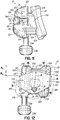
- the lingual side 20 of the bracket body 12 includes a projecting portion 124 that couples to a tooth (not shown) or pad 32, as shown in Fig. 11 .
- the projecting portion 124 includes an occlusal surface 126, a gingival surface 128, a mesial surface 130, a distal surface 132, and a lingual surface 134 that couples to pad 32, for example.
- the projecting portion 124 is configured to allow effective use of tie wings 136, as shown in Fig. 12 .
- the gingival-occlusal extent or height of the projecting portion 124 may be varied in a mesial-distal direction to facilitate use of the tie wings 136.
- the projecting portion 124 has a mesial-distal dimension substantially equal to the mesial-distal dimension of a more labial portion of the bracket body 12.
- the mesial side 26 of the bracket body 12, which includes mesial surface 130 of the projecting portion 124, is generally smooth and continuous.
- the distal side 28 of the bracket body 12, which includes distal surface 132, is also generally smooth and continuous ( Fig. 11 ).
- tie wings 136 are located along the occlusal and gingival sides 22, 24 of the bracket body 12 and generally extend therefrom, there is a reduction in the gingival-occlusal dimension of the projecting portion 124 relative to the more labial portion of the bracket body 12 having tie wings 136, as shown in Fig. 11 .
- Such a reduction, indicated by R 1 in Fig. 12 is due to the nature of a tie wing based orthodontic bracket.
- typical tie wing brackets generally position the tie wings adjacent the mesial and distal sides of the bracket body.
- the gingival-occlusal dimension of the projecting portion 124 adjacent the mesial and distal surfaces 130, 132 may be further reduced so as to effectively increase the working height of the tie wings 136. This further reduction is indicated by R 2 in Fig. 12 .
- projecting portion 124 has a gingival-occlusal dimension A intermediate the mesial and distal surfaces 130, 132 and a gingival-occlusal dimension B adjacent the mesial and distal surfaces 130, 132 that is less than the dimension A.
- the dimension A may be determined by design considerations such as strength, rigidity, structural integrity, or other factors. As further illustrated in Fig. 12 , however, the reduction to dimension B adjacent the mesial and distal surfaces 130, 132 relative to the intermediate dimension A provides an effective increase in the working height W of the tie wings 136 thereby providing enhanced functionality thereof.
- such an increase in the working height W of the tie wings 136 may be achieved by forming chamfers in the occlusal and gingival surfaces 126, 128.
- the occlusal surface 126 of projecting portion 124 may slope in a gingival direction from a mesial-distal intermediate location to the mesial-distal surfaces 130, 132 thereof to form chamfers 138.
- the gingival surface 128 of projecting portion 124 may slope in an occlusal direction from a mesial-distal intermediate location to the mesial-distal surfaces 130, 132 thereof to form chamfers 140.
- chamfers 140 may vary (together or relative to each other) depending on the specific application.
- Those of ordinary skill in the art will further recognize other configurations that reduce the gingival-occlusal dimension relative to an intermediate dimension so as to increase the working height W of the tie wings 136.
- the spring pin 66 is inserted into the bore 70 such that the slit 72 therein is aligned with the flat 142, as shown in Fig. 12 . Consequently, attempts to rotate the spring pin 66 relative to the bore 70 results in the edges that define slit 72 contacting the flat 142, thus preventing any relative rotation therebetween.
- a further feature which may enhance the functionality and use of orthodontic bracket 10 includes a tool receptacle that cooperates with a tool for moving the ligating slide 14 away from the closed position and toward the opened position in an improved manner.
- the labial side 30 of bracket body 12 may include a tool receptacle 144 defining an occlusal wall 146, a mesial wall 148, and a distal wall 150.
- the receptacle 144 is open along a gingival end thereof so as to be accessible to at least a portion of ligating slide 14.
- the tool receptacle 144 may be open to the occlusal edge 118 of ligating slide 14.
- the tool receptacle 144 may be configured to receive the tip 154 of a tool 156 that facilitates opening the ligating slide 14 in a manner described below.
- the tip 154 of the tool 156 is inserted into the tool receptacle 144 and rotated in either the clockwise or counter clockwise direction (clockwise shown in Fig. 13 ).
- a portion of the tip 154 bears against the occlusal wall 146 of the receptacle 144 and another portion of the tip 154 bears against the occlusal edge 118 of the ligating slide 14.
- the torque applied to the tool 156 is sufficient to overcome the opening force imposed by the securing mechanisms, as described above, such that the ligating slide 14 moves in the gingival direction relative to the bracket body 12 toward the opened position.
- the tool 156 may continue moving the ligating slide 14 until the tool 156 has been rotated about ninety degrees from its original position within receptacle 144.
- the maximum length 158 of the tip 154 of tool 156 should not exceed the length of travel of the ligating slide 14 relative to the bracket body 12.
- the length 158 of tip 154 should not exceed the length of the retaining slot 68 in the ligating slide 14, for example.
- the tool receptacle 144 may be formed substantially within the bracket body 12, the invention is not so limited.
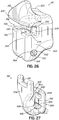
- the tool receptacle may be formed substantially within the ligating slide such that, for example, the occlusal end of the tool receptacle is open and a tool inserted therein may contact a gingival edge of the bracket body 12 (e.g., see Fig. 27 ).
- part of the tool receptacle may be formed in the bracket body and part of the tool receptacle may be formed in the ligating slide (not shown).
- the tool receptacle 144 as described above may provide some advantages.
- the orthodontic bracket 10 including a tool receptacle 144 as described above, and methods of using tool 156 for opening the ligating slide 14 may permit a decrease in the force transmitted to the tooth of the patient.
- the tool receptacle 144 results in contact of the opening tool 156 with both the ligating slide 14 and the bracket body 12, forces that would otherwise be transmitted to the tooth of the patient may be transmitted to the bracket body 12.
- the forces applied to the orthodontic bracket 10 as a whole during the opening of the ligating slide 14 effectively cancel each other out so that a negligible net force is transmitted to the tooth of the patient.
- Such a balancing out of the forces applied during opening of the ligating slide 14 prevents or reduces the discomfort associated with the transmission of a force to the tooth of the patient.
- the ligating slide 14 may be configured to "overshoot" the archwire slot 16, and in particular, overshoot slot surface 36.
- a cutout 160 may be formed in the labial side 30 of the bracket body 12 adjacent slot surface 36 that defines a ledge 162 which extends above slot surface 36 and which is configured to engage the lingual side 74 of ligating slide 14 when the ligating slide 14 is in the closed position.
- the occlusal side of the bracket may be contoured or profiled such that as the teeth are brought together, there is no interference between the bracket and the teeth on the opposing jaw.
- the bracket may be desirable to couple the molar bracket to adjacent orthodontic devices using ligature wire, elastic bands, or other connecting members known in the art.
- tie wings are typically omitted from molar brackets. Accordingly, the bracket as a whole may be used to secure the ligature, band, etc. thereto.
- brackets may lack suitable attachment points for receiving the ligature or elastic band and for maintaining the ligature or band at a relatively fixed location relative to the bracket. This may particularly be the case, for example, along the occlusal side of the molar bracket.
- the occlusal side of molar self-ligating brackets may be contoured, such as by being directed downwardly in a gingival direction (when carried on the lower jaw, for example), to avoid contact with the teeth on the opposing jaw. While effective to avoid contact with the opposing teeth, such contouring may allow a ligature or band secured around the bracket to slide along the occlusal side of the bracket. Such movement of the ligature or band may be undesirable and may diminish the effectiveness of the treatment.
- a self-ligating molar bracket 210 has features similar to that shown in Figs. 1-4 and those features have similar reference numbers but are preceded by the number 2.
- the ligating slide 214 moves along a slide engagement track 246 that is angled relative to the base surface 234 of the archwire slot 216.
- engagement track 246 extends generally along a translation plane 246a that is angled relative to a base plane 234a associated with the base surface 234.
- occlusal side 222 of the bracket body 212 may be generally contoured by directing at least a portion of the occlusal side 222 in a labial-gingival direction (i.e., slopes downwardly in reference frame of drawing).
- the occlusal side 222 of the bracket body 212 may include a cutout 300 adjacent the lingual side 220 thereof.
- the cutout 300 defines a groove 302 configured to receive a connecting member, such as a ligature or band 304, schematically shown in phantom in Fig. 15 .
- the groove 302 is bounded in the labial-lingual direction so as to prevent or reduce the likelihood of movement of the ligature or band 304 relative to the bracket body 212 during use.
- the groove 302 may be V-shaped, U-shaped, or have some other shape that facilitates the capture of a ligature or band therein.
- the groove 302 may be bounded in the labial direction by a sloped bounding surface 306 of the occlusal side 222, and may be bounded by the pad 232 in the lingual direction.
- the bounding surface 306 may be angled so as to generally face the tooth (i.e., has a surface normal that points toward the tooth) while the remainder of the occlusal side 222 generally faces away from the tooth (i.e., has a surface normal that points away from the tooth).
- Such a configuration maintains the ligature or band 304 in a relatively fixed location relative to the bracket body 212 and, in particular, prevents the ligature or band 304 from sliding in a labial direction along the occlusal side 222 of the bracket 210 and away from the tooth during use.
- the orthodontic bracket 210 may incorporate other features as disclosed in the previous embodiments.
- the bracket 210 may incorporate one of the securing mechanisms described above, the torque indicia, the horizontal slot, the tool receptacle, the chamfer or radiused feature at the occlusal end of the ligating slide, the matching system between ligating slide and bracket body, and/or other features described more fully above.
- aspects described for orthodontic bracket 10 may also provide benefits to molar brackets.
- ligating slide 214 may include other features more fully disclosed in U.S. Patent No. 7,267,545 .
- the lingual side 274 of ligating slide 214 may be angled adjacent the occlusal edge so that the archwire slot 216 more closely conforms to the cross-sectional shape of the archwire (now shown).
- ligating slide 214 cooperates with bracket body 212 to define a generally rectangular archwire slot 216 when the ligating slide 214 is in the closed position.
- brackets include labial surfaces that are irregular or discontinuous. In some situations, these irregularities may cause discomfort to the patient as, for example, soft oral tissue repeatedly engages the labial surface of the bracket. This discomfort or irritation may be particularly acute for rear portions of the oral cavity (e.g., brackets on the molar teeth) as oral tissue is generally tighter relative to more anterior portions of the oral cavity.
- many conventional brackets include regular, generally planar exterior surfaces. During mastication, food or other material in the oral cavity impacts against these surfaces. These surfaces are arranged such that, instead of deflecting the material away from the bracket, a substantial portion of the mastication force is transferred to the orthodontic bracket. The increased forces transferred to the bracket increase the chances of breaking the bracket or otherwise preventing proper operation thereof.
- Fig. 16 illustrates an orthodontic bracket 410 designed to address these and other shortcomings.
- the bracket 410 has features similar to that shown in Figs. 1-4 and those features have similar reference numerals but are preceded by the number 4.
- the bracket 410 as shown in the figures is configured and described for an upper molar tooth. However, as discussed above, those of ordinary skill in the art will appreciate that features of the bracket 410, as described below, may apply to brackets on other teeth, in different orientations, and/or in different areas of the oral cavity.
- the labial side 430 of the orthodontic bracket 410 is configured to be relatively smooth and continuous.
- a smooth and continuous feature to bracket 410 may be accomplished using generally large radius of curvature surfaces and/or transitions between adjacent sides of the bracket 410.
- Such a configuration may be achieved primarily by modifying the design of the ligating slide 414.
- the design of the bracket body 412 may also be modified to achieve improved comfort.
- the bracket body 412 generally includes a planar support surface 440 and a pair of opposed guides 442, 444 that collectively define a T-shaped slide engagement track 446 for ligating slide 414.
- the guides 442, 444 do not overlie the labial surface 476 of ligating slide 414 (e.g., contrast Figs. 1 and 16 , for example).
- the ligating slide 414 has an engagement portion 500 for engaging the bracket body 412 and an outer contoured portion 502 that forms a significant portion of the labial side 430 of the orthodontic bracket 410.
- the engagement portion 500 has a T-shaped configuration defining a head 504 having a mesial-distal cross dimension that is slightly less than a mesial-distal cross dimension of the slide engagement track 446 in bracket body 412 so as to be movable therein.
- Engagement portion 500 further includes a neck 506 that has a mesial-distal cross dimension less than the mesial-distal cross dimension of head 504 and is slightly less than the mesial-distal spacing between the guides 442, 444 so as to be movable therein.
- the contoured portion 502 has a mesial-distal cross dimension larger than that of neck 506 and which extends substantially from the mesial side 426 to the distal side 428 of bracket body 412.
- a lingual side 508 of contoured portion 502 overlies the guides 442, 444 so that the guides 442, 444 are not visible as viewed from the labial side 430 of bracket 410 ( Fig. 16 ).
- Contoured portion 502 further includes labial side 476 that is generally smooth and contoured, which is in contrast to the irregular configuration of conventional brackets.
- the labial side 476 may be generally arcuate and characterized by a relatively large radius of curvature.
- the relatively large radius of curvature may be directed to the mesial-distal curvature and/or the occlusal-gingival curvature.
- the radius of curvature for a substantial portion of labial side 476 in the mesial-distal direction may have a single value from mesial side 426 to distal side 428 (e.g., forms a portion of a circle).
- the radius of curvature may range between approximately 0.125 inches and approximately 0.375 inches.
- the radius of curvature may be approximately 0.200 inches.
- the radius of curvature in the mesial-distal direction may include a plurality of discrete values, with each value being relatively large, such as in the range provided above.
- the radius of curvature in the gingival-occlusal direction may also include one or more values.
- the labial side 476 may include generally flat portion 520 (e.g., very large radius of curvature) adjacent the gingival edge 522 and a transition portion 524 having a radius of curvature of between approximately 0.020 inches and approximately 0.075 inches.
- the generally flat portion in view of Fig. 20 ) may alternatively be formed as a curved or arcuate surface having a radius of curvature as provided above for the mesial-distal direction, for example.
- the primary labial surface as well as the transitions (if any) from the mesial and distal sides 426, 428 and/or the occlusal and gingival side 422, 424 of the bracket 410 to the labial side 430 of the bracket 410 are not sharp or irregular, but are smooth and gradual.
- Such a configuration eliminates or reduces the sources of discomfort to the patient when oral tissue contacts the bracket 410, and further facilitates movement of soft oral tissue over the bracket 410 resulting in an overall improvement to the comfort of the orthodontic bracket 410.
- the occlusal side 530 of ligating slide 414 may include a generally flat portion 532 (e.g., a very large radius of curvature) which transitions smoothly with the labial side 476 of the ligating slide 414, such as at transition portion 524 described above.
- the occlusal side 530 may be angled or sloped generally in the gingival direction and relative to the occlusal plane of the teeth (not shown).
- the occlusal side 422 of the bracket body 412 may also be sloped or contoured in the gingival direction so that the ligating slide 414 and bracket body 412 are relatively flush or smooth along occlusal side 422 when the ligating slide 414 is in the closed position.
- the occlusal side 530 of slide 414 has been described as having generally flat portion 532, this portion may also be curved in one or both of the mesial-distal direction or the gingival-occlusal direction.
- the orthodontic bracket 410 may incorporate other features as disclosed in the previous embodiments.
- the bracket 410 may incorporate one of the securing mechanisms described above, the torque indicia, the horizontal slot, the tool receptacle, the chamfer or radiused feature at the end of the ligating slide, the matching system between ligating slide and bracket body, and/or other features described more fully above.
- the orthodontic bracket 410 may include a securing mechanism including a spring pin 466 associated with bracket body 412 and a retaining slot 468 formed in the ligating slide 414. Due to size constraints and other design considerations, the retaining slot 468 may be formed in the lingual side 508 of the contoured portion 502 of ligating slide 414. Because the retaining slot 468 extends into the engagement portion 500 ( Fig. 19 ), the engagement portion 500 includes a U-shaped cutout 540 thereby allowing the spring pin 466 to access the retaining slot 468.
- the bracket body 412 may include a boss or pin support 542 that extends labially from the support surface 440.
- the pin support 542 has a shape corresponding to cutout 540 and is received in the U-shaped cutout 540 as the ligating slide 414 is moved between the opened and closed positions.
- the spring pin 466 and retaining slot 468 operate in basically the same manner described above to secure the ligating slide 414 in at least the closed position. Additionally, the spring pin 466 and retaining slot 468 may prevent the ligating slide 414 from disengaging from the bracket body 412, as described more fully above.
- the orthodontic bracket 10 shown in Figs. 1-3 may include another feature that improves the use and functionality of the bracket.
- bracket 10 includes a horizontally-oriented slot 122 (e.g., directed generally in the mesial-distal direction) for securing various orthodontic devices.
- slot 122 e.g., directed generally in the mesial-distal direction
- the orthodontic bracket 10 may include a vertical slot 600 (e.g., directed generally in the gingival-occlusal direction).
- the vertical slot 600 may be configured, for example, to receive a variety of temporary attachment devices, such as, for example, removable hook 602, as illustrated in Fig. 21 .
- temporary attachment devices such as, for example, removable hook 602
- Those of ordinary skill in the art will recognize other permanent or temporary orthodontic devices that may be used with vertical slot 600 to effectuate orthodontic treatment.
- Horizontal and vertical slots 122, 600 may be configured so as not to interfere with each other when both are utilized on orthodontic bracket 10.
- the horizontal slot 122 may be disposed adjacent tie wings 136
- the vertical slot 600 may be disposed in projecting portion 124.
- projecting portion 124 includes a generally gingival-occlusal directed passage 604 having a first opening (not shown) in the occlusal side 126 of projecting portion 124 and a second opening 606 in the gingival side 128 of projecting portion 124.
- vertical slot 600 may be disposed adjacent the lingual side 20 of the bracket body 12 such that passage 604 is at least partially defined or bounded by pad 32.
- vertical slot 600 may instead be disposed in other portions of the bracket body 12 and/or not necessarily be defined by any portion of the pad 32.
- additional slots may be formed in orthodontic bracket 10.
- additional vertical slots (not shown) may be formed in projecting portion 124.
- Orthodontic treatment of teeth may be enhanced by properly locating the brackets on the surface of the teeth.
- properly locating the brackets on the teeth in the gingival-occlusal direction is desirable. This may be done, for example, by using a fixed reference point on the tooth and basing various measurements to ensure proper positioning of a bracket from this fixed reference point.
- the occlusal edge of the tooth is used as the fixed reference point.
- a tool is used to position the brackets on the teeth relative to the fixed reference point.
- the tool is typically a separate component supplied to the orthodontist independent of the orthodontic brackets.
- the orthodontist must, in some fashion, and in the office environment, couple the bracket to the tool so as to properly position the bracket on the surface of the tooth. This type of field assembly process can be difficult, frustrating, tedious, and time consuming.
- an orthodontic assembly 650 includes an alignment device 652 coupled to a self-ligating orthodontic bracket 10 to facilitate deployment and installation thereof onto a tooth 654.
- the assembly 650 may, for example, be pre-packaged and provided to the orthodontist in a coupled or assembled condition (as shown).
- the alignment device 652 may be designed so as to be disposable.
- the alignment device 652 may be separated from the bracket 10 and simply discarded.
- the alignment device 652 may be formed in a cost-effective manner that makes its disposal feasible.
- alignment device 652 includes an elongate handle portion 656 and a bracket coupling portion 658 offset from and extending from the handle portion 656.
- Handle portion 656 facilitates deployment of the bracket 10 onto a tooth 654 by providing a gripping portion that an orthodontist may utilize to grasp the assembly 650 and deploy the bracket 10 into a patient's mouth and onto tooth 654.
- handle portion 656 facilitates positioning of the bracket 10 in the occlusal-gingival direction relative to tooth 654.
- handle portion 656 includes one or more marking elements, for example, in the form of ribs 660, which allow the user to precisely place the bracket 10 in a desired occlusal-gingival position on the tooth 654.
- the exemplary ribs 660 are spaced from one another by predetermined distances (e.g., 1 mm) and each is also spaced from a central axis 662 of the archwire slot 16 by a predetermined distance. Accordingly, a user may, for example, place the bracket 10 in an occlusal-gingival position such that one of the ribs 660 is in alignment with the occlusal edge 664 of tooth 654. This positioning, in turn, gives the user certainty as to the occlusal-gingival position of the bracket 10 relative to the tooth 654.
- predetermined distances e.g. 1 mm
- handle portion 656 facilitates the positioning described above. More specifically, the handle portion 656 is designed such that, when bracket coupling portion 658 is coupled to a bracket 10 having a bonding surface and the bonding surface engages the surface of the tooth 654, handle portion 656 also lies adjacent the surface of tooth 654. For example, the offset relationship between the handle portion 656 and bracket coupling portion 658 facilitates positioning of handle portion 656 adjacent tooth 654 during use. This configuration allows the user to more precisely ascertain the position of the ribs 660 relative to the tooth 654. In this regard, the design of handle portion 656 facilitates the reduction or prevention of parallax errors during deployment of orthodontic bracket 10 onto tooth 654, especially, for example, in the rear of the oral cavity.
- the alignment device 652 may be configured for secured coupling with the bracket 10.
- the alignment device 652 may be configured to prevent or reduce relative movement between the bracket 10 and alignment device 652 in the mesial-distal direction.
- the alignment device 652 may include a first coupling feature that cooperates with a second coupling feature on the bracket 10 to prevent relative movement in the mesial-distal direction.
- the first coupling feature may include a tab 666 and the second coupling feature may include a recess, such as, for example, the tool receptacle 144 ( Fig. 21 ).
- the tab 666 When the alignment device 652 is coupled to orthodontic bracket 10, the tab 666 fits tightly within the tool receptacle 144 of the bracket 10. Accordingly, the mesial and distal walls 148, 150 of tool receptacle 144 may abut exposed surfaces of tab 666 to limit or restrict mesial-distal movement of the alignment device 652 relative to orthodontic bracket 10. This type of coupling permits deployment of the bracket 10 onto the tooth 654 without a concern for mesial-distal shifting of the alignment device 652 and bracket 10 relative to one another. Moreover, the coupling of tab 666 of the alignment device 652 with tool receptacle 144 permits coupling of device 652 with bracket 10 in only one orientation and position, which may be desirable, for example, during assembly of orthodontic assembly 650.
- the alignment device 652 may be further configured to prevent or reduce relative movement between the bracket 10 and alignment device 652 in the gingival-occlusal direction.
- the bracket coupling portion 658 includes a leg 668 that extends for at least a portion of the length of the archwire slot 16 and fits tightly therein to facilitate frictional engagement of bracket 10 with alignment device 652.
- Leg 668 includes an occlusal surface 670 that abuts slot surface 36 of archwire slot 16, and a gingival surface 672 that abuts the opposed slot surface 38 of archwire slot 16.
- the gingival and occlusal surfaces 670, 672 may include ribs 674 for enhancing the frictional engagement of these surfaces with slot surfaces 36, 38 respectively, of archwire slot 16.
- bracket 10 may be deployed on the tooth 654 without a concern for gingival-occlusal shifting of the alignment device 652 and bracket 10 relative to one another.
- the alignment device 652 may be formed from a suitable plastic material and through, for example, a molding process.
- the alignment device may be molded from polymers, including, for example, polypropylene.
- the material may be selected such that at least leg 668 is somewhat deformable or compressible. In this way, for example, leg 668 may be slightly deformed or compressed when in archwire slot 16 to facilitate the coupling between alignment device 652 and bracket 10.
- the alignment device 652 may have visual features that permit a user or manufacturer to identify a unique type of bracket 10 to which device 652 may be coupled.
- alignment device 652 may have a color that corresponds to a specific type of bracket 10.
- the alignment device 652 may include indicia (e.g., alphanumeric, symbolic, etc.) that match indicia on the orthodontic bracket 10.
- the spring pin 66 was oriented generally perpendicular to the archwire slot 16.
- the spring pin 66 generally projected in the labial-lingual direction.
- the spring pin 66 may be oriented in a direction that is generally parallel to the archwire slot 16.
- Figures 24 and 25 in which features similar to that shown in Figs. 1-4 have similar reference numerals but are preceded by the number 7, illustrate a self-ligating bracket 710 having a spring pin 766 oriented in a generally mesial-distal direction.
- orthodontic bracket 710 includes a bracket body 712 including a pair of guides 742, 744 that overlie in spaced relation a support surface 740 that defines a slide engagement track 746 for receiving a ligating slide 714.
- Each of the guides 742, 744 includes a bore 800, 802, respectively, that receives a portion of spring pin 766 therein such that the spring pin 766 is generally parallel to the archwire slot 716 and extends across the slide engagement track 746. While the embodiment shown in Fig. 24 shows the spring pin 766 extending into both guides 742, 744, it should be recognized that in alternative embodiments, the spring pin 766 may extend from only one of the guides 742, 744. At least one of the bores 800, 802 may be open at the mesial or distal sides 726, 728 for inserting the spring pin 766 within bores 800, 802 during assembly.
- a retaining slot 804 may be formed in the lingual side 774 of the ligating slide 714 and extends generally in the gingival-occlusal direction. In one embodiment, the retaining slot 804 also extends across the mesial-distal extent of the ligating slide 714. In alternative embodiments, however, the retaining slot 804 may extend for a portion of the mesial-distal extent of ligating slide 714.
- the retaining slot 804 is shaped in the gingival-occlusal direction so as to cooperate with spring pin 766 and secure the ligating slide 714 in at least the closed position relative to bracket body 714.
- retaining slot 804 includes a first arcuately shaped recess 806 adjacent the gingival end 779, and a second arcuately shaped recess 808 adjacent the occlusal end 782.
- a raised ridge portion 810 is intermediate the first and second arcuately shaped recesses 806, 808.
- the spring pin 766 (e.g., a lateral surface thereof) is disposed in the first arcuately shaped recess 806 of retaining slot 804 and is permitted to radially expand such that the spring pin 766 engages the wall of recess 806.
- the spring pin 766 does not have to engage the wall of first arcuately shaped recess 806, but must at least have a cross dimension when radially expanded such that the spring pin 766 engages the ridge portion 810 as the ligating slide 714 is moved toward the opened position.
- the raised ridge 810 When so disposed in the first arcuately shaped recess 806, the raised ridge 810 provides a threshold level of resistance to any movement of the ligating slide 714 away from the closed position and toward the opened position. However, if a sufficiently large opening force is applied to ligating slide 714 in, for example, the gingival direction, the interaction between the retaining slot 804 and spring pin 766 causes the pin 766 to radially contract (due to squeezing imposed by raised ridge 810) so that spring pin 766 moves along raised ridge 810.
- the spring pin 766 bears against a lingual surface thereof such that a threshold sliding force, which is less than, and perhaps significantly less than the opening force, must be imposed to overcome the drag and move the ligating slide 714 relative to the bracket body 712 as spring pin 766 traverses raised ridge 810.
- a threshold sliding force which is less than, and perhaps significantly less than the opening force, must be imposed to overcome the drag and move the ligating slide 714 relative to the bracket body 712 as spring pin 766 traverses raised ridge 810.
- the ligating slide 714 does not just freely slide or drop to the fully opened position, but must be purposefully moved toward the opened position. If the ligating slide 714 is only partially opened, the slide 714 may be configured to maintain its position relative to the bracket body 712 (due to the friction forces) until the threshold sliding force is imposed to continue moving the slide 714 toward the opened position.
- the spring pin 766 recovers or snaps back to its radially expanded position as the spring pin 766 enters the first arcuately shaped recess 806 to once again secure the ligating slide 714 in the closed position.
- the amount of force required to overcome the threshold sliding force as the spring pin 766 moves relative to the raised ridge portion 810 may vary during movement between the opened and closed positions of ligating slide 714.
- the raised ridge portion 810 may have a height that slightly tapers so as to increase in the direction of the occlusal end 782 of the retaining slot 804 (not shown). Accordingly, the sliding force required for relative movement between the spring pin 766 and the retaining slot 804 of ligating slide 714 decreases as the ligating slide 714 is moved toward the opened position and increases as the ligating slide 714 is moved toward the closed position.
- Those of ordinary skill in the art may recognize other ways to vary the sliding force of the ligating slide 714 as the slide is moved between the opened and closed positions.
- the embodiment shown in Fig. 25 includes second arcuately shaped recess 808 adjacent the occlusal end 782.
- the ligating slide 714 may be secured in the opened position so as to require a sufficiently high closing force to initiate movement of the ligating slide 714 away from the opened position and toward the closed position.
- the spring pin 766 is disposed in the first arcuately shaped recess 806 and a sufficiently large opening force must be applied to the ligating slide 714 in the gingival direction to contract spring pin 766 and allow the pin 766 to move onto raised ridge portion 810.
- the spring pin 766 snaps back to its radially expanded position as the spring pin 766 enters second arcuately shaped recess 808 at the occlusal end 782 of the retaining slot 804.
- the raised ridge portion 810 provides a threshold level of resistance to any movement of the ligating slide 714 away from the opened position and toward the closed position. Only after a sufficiently large closing force is applied to the ligating slide 714 in the occlusal direction, will the spring pin 766 radially contract so that the spring pin 766 moves onto the raised ridge portion 810 of the retaining slot 804.
- orthodontic bracket 910 includes a bracket body 912 including a pair of guides 942, 944 that overlie in spaced relation to a support surface 940 that defines a slide engagement track 946 for receiving a ligating slide 914.
- Each of the guides 942, 944 includes a bore 1002 (one shown) that receives a portion of spring pin 966 therein such that the spring pin 966 is generally parallel to the archwire slot 916 and extends across the slide engagement track 946. While the embodiment shown in Fig.
- the spring pin 966 may extend from only one of the guides 942, 944. At least one of the bores in guides 942, 944 may be open at the mesial or distal sides 926, 928 for inserting the spring pin 966 therein during assembly.
- the ligating slide 914 includes an engagement portion 1004 for engaging bracket body 912 and an outer portion 1006 that forms a portion of the labial side 930 of the orthodontic bracket 910.
- the engagement portion 1004 has a T-shaped configuration defining a head 1008 having a mesial-distal cross dimension that is slightly less than a mesial-distal cross dimension of the slide engagement track 946 in bracket body 912 so as to be movable therein.
- Engagement portion 1004 further includes a neck 1010 that has a mesial-distal cross dimension less than the mesial-distal cross dimension of head 1008 and is slightly less than the mesial-distal spacing between the guides 942, 944 so as to be movable therein.
- the outer portion 1006 has a Y-shaped configuration configured to cover a substantial portion of the archwire slot 916 in the mesial-distal direction as well as to define a tool receptacle 1011 for receiving a tool and opening the ligating slide 914 in accordance with that discussed above.
- a retaining slot 1012 is formed in the ligating slide 914 and extends generally in the gingival-occlusal direction.
- the retaining slot 1012 may be positioned at least in the neck 1010 of engagement portion 1004 and may be formed as a through slot, e.g., extending from the mesial side of the neck 1010 to the distal side of the neck 1010.
- the retaining slot 1012 may also be formed in the neck 1010 as a blind slot.
- the retaining slot 1012 is shaped so as to cooperate with spring pin 966 and secure the ligating slide 914 in at least the closed position relative to bracket body 912.
- retaining slot 1012 includes a first enlarged portion 1014 adjacent the gingival end 1016 of retaining slot 1012 in communication with a straight segment portion 1018 similar to that shown in Fig. 4B .
- the retaining slot 1012 may further include a second enlarged portion 1020 adjacent an occlusal end 1022, similar to that shown in Fig. 5 .
- the spring pin 966 (e.g., a lateral surface thereof) is disposed in the first enlarged portion 1014 of retaining slot 1012 and is permitted to radially expand such that the spring pin 966 engages the wall of enlarged portion 1014.
- the spring pin 966 does not have to engage the wall of first enlarged portion 1014, but must at least have a cross dimension when radially expanded that is larger than the cross dimension of the straight segment portion 1018.
- the protrusions at the transition between the first enlarged portion 1014 and straight segment portion 1018 provide a threshold level of resistance to any movement of the ligating slide 914 away from the closed position and toward the opened position.
- the interaction between the retaining slot 1012 and spring pin 966 causes the pin 966 to radially contract (due to squeezing imposed by the slot) so that spring pin 966 moves past the protrusions and into the straight segment portion 1018.
- the spring pin 966 bears against the walls thereof such that a threshold sliding force, which is less than, and perhaps significantly less than the opening force, must be imposed to overcome the drag and move the ligating slide 914 relative to the bracket body 912 as spring pin 966 traverses straight segment portion 1018.
- a threshold sliding force which is less than, and perhaps significantly less than the opening force, must be imposed to overcome the drag and move the ligating slide 914 relative to the bracket body 912 as spring pin 966 traverses straight segment portion 1018.
- the ligating slide 914 does not just freely slide or drop to the fully opened position, but must be purposefully moved toward the opened position. If the ligating slide 914 is only partially opened, the slide 914 may be configured to maintain its position relative to the bracket body 912 (due to the friction forces) until the threshold sliding force is imposed to continue moving the slide 914 toward the opened position.
- the spring pin 966 recovers or snaps back to its radially expanded position as the spring pin 966 enters the enlarged portion
- the amount of force required to overcome the threshold sliding force as the spring pin 966 moves relative to the straight segment portion 1018 may vary during movement between the opened and closed positions of ligating slide 914, such as by varying the cross dimension of straight segment portion 1018.
- Those of ordinary skill in the art may recognize other ways to vary the sliding force of the ligating slide 914 as the slide is moved between the opened and closed positions.
- the embodiment shown in Fig. 27 includes second enlarged portion 1020 adjacent the occlusal end 1022.
- the ligating slide 914 may be secured in the opened position so as to require a sufficiently high closing force to initiate movement of the ligating slide 914 away from the opened position and toward the closed position.
- the spring pin 966 is disposed in the first enlarged portion 1012 and a sufficiently large opening force must be applied to the ligating slide 914 in the gingival direction to contract spring pin 966 and allow pin 966 to move into straight segment portion 1018.
- the spring pin 966 snaps back to its radially expanded position as the spring pin 966 enters second enlarged portion 1020 at the occlusal end 1022 of the retaining slot 1012.
- the protrusions at the transition between the second enlarged portion 1020 and straight segment portion 1018 provide a threshold level of resistance to any movement of the ligating slide 914 away from the opened position and toward the closed position. Only after a sufficiently large closing force is applied to the ligating slide 914 in, for example, the occlusal direction, will the spring pin 966 radially contract so that the spring pin 966 moves into straight segment portion 1018 of the retaining slot 1012.
Applications Claiming Priority (3)
| Application Number | Priority Date | Filing Date | Title |
|---|---|---|---|
| US94684207P | 2007-06-28 | 2007-06-28 | |
| US2257008P | 2008-01-22 | 2008-01-22 | |
| PCT/US2008/068545 WO2009006286A2 (en) | 2007-06-28 | 2008-06-27 | Self-ligating orthodontic bracket and devices for deploying same |
Publications (2)
| Publication Number | Publication Date |
|---|---|
| EP2170210A2 EP2170210A2 (en) | 2010-04-07 |
| EP2170210B1 true EP2170210B1 (en) | 2018-08-15 |
Family
ID=39735046
Family Applications (1)
| Application Number | Title | Priority Date | Filing Date |
|---|---|---|---|
| EP08772143.7A Active EP2170210B1 (en) | 2007-06-28 | 2008-06-27 | Selbstligierende orthodontische Klammmer |
Country Status (12)
| Country | Link |
|---|---|
| US (1) | US8033824B2 (zh) |
| EP (1) | EP2170210B1 (zh) |
| JP (4) | JP5215391B2 (zh) |
| KR (1) | KR101183406B1 (zh) |
| CN (2) | CN101815478B (zh) |
| AU (1) | AU2008270025A1 (zh) |
| BR (1) | BRPI0813295B8 (zh) |
| DE (3) | DE202008018568U1 (zh) |
| ES (1) | ES2684539T3 (zh) |
| MX (1) | MX2010000077A (zh) |
| RU (1) | RU2010102724A (zh) |
| WO (1) | WO2009006286A2 (zh) |
Families Citing this family (117)
| Publication number | Priority date | Publication date | Assignee | Title |
|---|---|---|---|---|
| US7267545B2 (en) | 2005-01-11 | 2007-09-11 | Ormco Corporation | Self-ligating orthodontic bracket |
| US7704072B2 (en) | 2006-04-19 | 2010-04-27 | Ormco Corporation | Orthodontic bracket |
| US20090155734A1 (en) * | 2006-04-19 | 2009-06-18 | Damon Dwight H | Orthodontic bracket |
| US9554875B2 (en) | 2006-09-07 | 2017-01-31 | Rmo, Inc. | Method for producing a customized orthodontic appliance |
| US8251697B2 (en) | 2006-09-07 | 2012-08-28 | Rmo, Inc. | Reduced-friction buccal tube and method of use |
| US8979528B2 (en) | 2006-09-07 | 2015-03-17 | Rmo, Inc. | Customized orthodontic appliance method and system |
| US8469704B2 (en) * | 2007-06-28 | 2013-06-25 | Ormco Corporation | Self-ligating orthodontic bracket and devices for deploying same |
| EP2008611A1 (en) * | 2007-06-28 | 2008-12-31 | Ormco Corporation | Orthodontic hand tools for use with a self-ligating orthodontic bracket, methods for using such orthodontic hand tools, self-ligating orthodontic brackets, and orthodontic bracket systems |
| MX367577B (es) * | 2008-08-13 | 2019-08-27 | Ormco Corp | Soporte de ortodoncia estetico y metodo para elaborar el mismo. |
| AU2009238317B2 (en) | 2008-11-14 | 2011-10-06 | Ormco Corporation | Surface treated polycrystalline ceramic orthodontic bracket and method of making same |
| DE102008060820A1 (de) * | 2008-12-05 | 2010-06-10 | Bernhard Förster Gmbh | Selbstligierendes Bracket für die Orthodontie |
| JP2012515067A (ja) * | 2009-01-16 | 2012-07-05 | オルムコ コーポレイション | 転位歯を矯正する歯科矯正ブラケットおよび方法 |
| CH700504A2 (de) * | 2009-03-10 | 2010-09-15 | Dominik A Troester Dr | Nicht-ligierendes Bracket für die linguale Orthodontie. |
| WO2010107567A1 (en) | 2009-03-16 | 2010-09-23 | Rmo, Inc. | Orthodontic bracket having an archwire channel and archwire retaining mechanism |
| US11219507B2 (en) | 2009-03-16 | 2022-01-11 | Orthoamerica Holdings, Llc | Customized orthodontic appliance and method |
| WO2010117927A1 (en) * | 2009-04-10 | 2010-10-14 | Ultradent Products, Inc. | Integral machined orthodontic bracket having hook with circular cross-sectioned shank |
| US20100285420A1 (en) * | 2009-05-07 | 2010-11-11 | Ormco Corporation | Orthodontic bracket having a lingually biased closure member and associated method |
| ITVI20090191A1 (it) * | 2009-07-27 | 2011-01-28 | Hdc S R L | Dispositivo ortodontico con un sistema di fissaggio auto-legante per apparecchi ortodontici con una parte filiforme |
| US9345558B2 (en) * | 2010-09-03 | 2016-05-24 | Ormco Corporation | Self-ligating orthodontic bracket and method of making same |
| CN101947138B (zh) * | 2010-09-10 | 2012-08-29 | 广州瑞通生物科技有限公司 | 一种通用舌侧托槽系统 |
| US9615897B2 (en) | 2010-09-10 | 2017-04-11 | Ormco Corporation | Self-ligating orthodontic bracket |
| EP3345567B1 (en) | 2010-12-08 | 2023-08-02 | Strite Industries Ltd. | Orthodontic gripping device |
| DE102010054006A1 (de) | 2010-12-09 | 2012-06-14 | Rehau Ag + Co. | Verfahren zur Verbesserung der Wärmedämmung eines Hohlkammerprofils sowie Hohlkammerprofil |
| CN102274081A (zh) * | 2011-05-09 | 2011-12-14 | 杭州西湖生物材料有限公司 | 牙用正畸自锁托槽系统 |
| WO2012154190A1 (en) | 2011-05-12 | 2012-11-15 | Rmo, Inc. | Orthodontic appliance with encoded information formed in the base |
| USD660436S1 (en) * | 2011-05-13 | 2012-05-22 | Rmo, Inc. | Orthodontic bracket |
| USD660968S1 (en) * | 2011-05-13 | 2012-05-29 | Rmo, Inc. | Orthodontic bracket |
| CN102228397B (zh) * | 2011-06-23 | 2012-12-05 | 广州瑞通生物科技有限公司 | 一种带正轴功能的个性化正畸矫治器 |
| USD847349S1 (en) | 2011-09-22 | 2019-04-30 | Rmo, Inc. | Orthodontic lock with flange |
| WO2013052691A1 (en) * | 2011-10-04 | 2013-04-11 | F-Cube, Ltd. | Method of making self-ligating orthodontic brackets and component parts |
| US20130224676A1 (en) * | 2012-02-27 | 2013-08-29 | Ormco Corporation | Metallic glass orthodontic appliances and methods for their manufacture |
| TWM444154U (zh) * | 2012-06-08 | 2013-01-01 | Micro Art Technology Co Ltd | 牙齒矯正器之自鎖定位裝置 |
| CN104822339B (zh) * | 2012-07-23 | 2018-03-27 | 3M创新有限公司 | 自锁正畸托槽 |
| CN102908196B (zh) * | 2012-08-27 | 2018-08-17 | 北京圣玛特科技有限公司 | 一种带有滑盖的自锁托槽 |
| US9427291B2 (en) | 2012-10-30 | 2016-08-30 | University Of Southern California | Orthodontic appliance with snap fitted, non-sliding archwire |
| US9364298B2 (en) * | 2012-11-08 | 2016-06-14 | Ormco Corporation | Orthodontic bracket having a biased slide member |
| US8992214B2 (en) * | 2012-11-13 | 2015-03-31 | Mem Dental Technology Co., Ltd. | Orthodontic self-ligating brackets |
| US9089386B2 (en) | 2012-11-16 | 2015-07-28 | World Class Technology Corporation | Self-ligating bracket with sliding cover |
| CN103027755A (zh) * | 2012-12-13 | 2013-04-10 | 广州瑞通生物科技有限公司 | 一种个性化舌侧自锁矫治器 |
| USD726318S1 (en) | 2013-01-17 | 2015-04-07 | Rmo, Inc. | Dental instrument for a self-ligating orthodontic clip |
| US9814543B2 (en) | 2013-02-16 | 2017-11-14 | Ormco Corporation | Methods for fabrication of orthodontic appliances and orthodontic appliances made thereby |
| US9468505B2 (en) | 2013-03-15 | 2016-10-18 | American Orthodontics Corporation | Self-ligating bracket |
| US9949806B2 (en) | 2013-03-15 | 2018-04-24 | Christopher C. Cosse | Orthodontic bracket assemblies with torque-adjusting drums |
| CN105102021B (zh) | 2013-04-10 | 2019-11-29 | 赛诺菲 | 药物输送装置的驱动机构 |
| CN105358090B (zh) * | 2013-06-14 | 2018-08-03 | 奥姆科公司 | 具有可旋转闭合件的自锁正畸托槽 |
| US10945815B2 (en) | 2013-08-19 | 2021-03-16 | Premier Orthodontics Designs, Lllp | Orthodontic bracket |
| US9198740B2 (en) | 2013-08-19 | 2015-12-01 | Premier Orthodontic Designs, Lllp | Orthodontic bracket |
| CA2955936C (en) | 2013-09-20 | 2017-09-12 | Brandon OWEN | Bracket system |
| US9844423B2 (en) * | 2013-10-03 | 2017-12-19 | Brandon Owen | Bracket extension system |
| US9861453B2 (en) * | 2013-10-03 | 2018-01-09 | Brandon Owen | Bracket extension system |
| USD721811S1 (en) | 2013-10-29 | 2015-01-27 | Rmo, Inc. | Orthodontic bracket |
| BR202013028685U2 (pt) * | 2013-11-07 | 2015-10-20 | Tecnident Equipamentos Ortodônticos Ltda | disposição construtiva aplicada em bráquete autoligado |
| US10456219B2 (en) | 2014-01-09 | 2019-10-29 | Ortho Solutions, LC | Orthodonic post and pin assembly |
| US9901420B2 (en) | 2014-02-25 | 2018-02-27 | Ormco Corporation | Orthodontic appliances including ferromagnetic shape memory alloys and methods of orthodontic treatment using same |
| TWI535425B (zh) * | 2014-05-15 | 2016-06-01 | Densmart Dental Co Ltd | 牙科矯正器用植體定位裝置 |
| US20160051343A1 (en) * | 2014-08-20 | 2016-02-25 | Orthoarm, Inc. | Kit of self-ligating brackets |
| WO2016043446A1 (ko) * | 2014-09-15 | 2016-03-24 | 휴비트 주식회사 | 치열교정용 브래킷 |
| KR102307454B1 (ko) * | 2014-10-27 | 2021-10-06 | 오스템올소돈틱스 주식회사 | 치열교정용 브래킷 |
| US10111731B2 (en) | 2014-11-18 | 2018-10-30 | American Orthodontics Corporation | Self-ligating bracket |
| US20160175072A1 (en) * | 2014-12-19 | 2016-06-23 | Ormco Corporation | Self-ligating orthodontic bracket with rotatable closure member |
| CN104526156A (zh) * | 2014-12-19 | 2015-04-22 | 上海埃蒙迪材料科技股份有限公司 | 一种分体正畸托槽半自动化激光焊接装置 |
| US9943383B2 (en) | 2014-12-19 | 2018-04-17 | Ormco Corporation | Biased pivoting slide orthodontic bracket |
| CN204468308U (zh) * | 2015-01-12 | 2015-07-15 | 梁甲兴 | 带状直丝弓托槽 |
| CN105982745B (zh) | 2015-01-29 | 2018-11-09 | 吉利 | 牵引托槽与正畸矫正系统及其矫正方法 |
| CN107530152B (zh) * | 2015-05-04 | 2021-02-09 | 第一齿科正畸设计公司 | 正畸托槽 |
| WO2016200944A1 (en) | 2015-06-08 | 2016-12-15 | American Orthodontics Corporation | Self-ligating bracket |
| CN104970890B (zh) * | 2015-06-24 | 2018-03-09 | 浙江普特医疗器械有限公司 | 一种牙齿正畸用锁片式自锁托槽 |
| US20170000588A1 (en) * | 2015-07-01 | 2017-01-05 | Ormco Corporation | Self-ligating orthodontic bracket with an external rotatable closure member |
| WO2017008183A1 (zh) * | 2015-07-10 | 2017-01-19 | 杭州星辰三比齿科器材有限公司 | 一种被动自锁托槽 |
| US10039618B2 (en) | 2015-09-04 | 2018-08-07 | Ormco Corporation | Orthodontic brackets |
| US10182885B2 (en) | 2015-10-29 | 2019-01-22 | Mem Dental Technology Co., Ltd | Self-ligating bracket |
| US10085824B2 (en) | 2015-10-30 | 2018-10-02 | Ortho Organizers, Inc. | Self ligating orthodontic bracket |
| US10660729B2 (en) * | 2015-11-18 | 2020-05-26 | Alexandre Gallo Lopes | Self-ligating bracket with cantilever locking beam mechanism and other locking elements for ligating sliding members, and methods of making and use thereof |
| KR20170076259A (ko) * | 2015-12-24 | 2017-07-04 | 휴비트 주식회사 | 치열교정용 브래킷 |
| CN117695035A (zh) * | 2016-04-18 | 2024-03-15 | 斯威夫特健康系统有限公司 | 具有非滑动的绑扎弓丝的牙齿正畸矫正器 |
| ITUA20164093A1 (it) * | 2016-06-03 | 2017-12-03 | Giovanbattista Pagnotta | Dispositivo ortodontico |
| KR101729995B1 (ko) * | 2016-06-10 | 2017-05-11 | 주식회사 바이오세텍 | 자가 결찰식 치열교정 브래킷 조립체 |
| USD804037S1 (en) | 2016-08-02 | 2017-11-28 | Henry Schein, Inc. | Self-ligating orthodontic bracket |
| CN106236296B (zh) * | 2016-08-23 | 2019-02-15 | 杭州西湖生物材料有限公司 | 一种双辅助孔低摩擦滑动自锁托槽 |
| JP6185130B1 (ja) * | 2016-09-10 | 2017-08-23 | 医療法人クリエイティングスマイルズ | 歯列矯正用インプラント装置 |
| KR102181459B1 (ko) * | 2016-09-21 | 2020-11-23 | 프리미어 오소돈틱 디자인스 엘엘엘피 | 치열 교정용 브래킷 |
| EP3547951A4 (en) | 2016-12-02 | 2020-07-01 | Swift Health Systems Inc. | SYSTEM FOR INDIRECT ORTHODONTIC BINDING AND METHOD FOR BRACKET PLACEMENT |
| US10881489B2 (en) | 2017-01-31 | 2021-01-05 | Swift Health Systems Inc. | Hybrid orthodontic archwires |
| USD958373S1 (en) | 2017-03-22 | 2022-07-19 | World Class Technology Corporation | Ligating member for an orthodontic bracket |
| US11612457B2 (en) | 2017-03-22 | 2023-03-28 | World Class Technology Corporation | Adjustable hook for orthodontic brackets |
| USD926993S1 (en) | 2017-11-21 | 2021-08-03 | World Class Technology Corporation | Ligating member for an orthodontic bracket |
| CA3055785C (en) * | 2017-03-22 | 2024-01-16 | World Class Technology Corporation | Adjustable hook for orthodontic brackets |
| US11612458B1 (en) | 2017-03-31 | 2023-03-28 | Swift Health Systems Inc. | Method of tongue preconditioning in preparation for lingual orthodontic treatment |
| EP3612129B1 (en) | 2017-04-21 | 2023-10-11 | Swift Health Systems Inc. | Indirect bonding tray having several handles |
| CN107019569A (zh) * | 2017-05-19 | 2017-08-08 | 吉利 | 自锁托槽及其开启方法 |
| AU2018299419B2 (en) * | 2017-07-11 | 2023-05-18 | Stewart Cullen | Mandibular advancement splint |
| US10575928B2 (en) | 2017-09-21 | 2020-03-03 | Brandon Owen | Orthodontic bracket retention anchor |
| US10779910B2 (en) * | 2017-09-25 | 2020-09-22 | Ormco Corporation | Orthodontic bracket axis indicator |
| CN109549721A (zh) * | 2017-09-25 | 2019-04-02 | 金华市柯帝夫医疗器械科技有限公司 | 一种自锁托槽 |
| CN107874850A (zh) * | 2017-10-31 | 2018-04-06 | 陈建文 | 一种牙齿矫正自锁托槽 |
| CN107714206B (zh) * | 2017-11-09 | 2021-05-14 | 广州欧欧医疗科技有限责任公司 | 正畸托槽及其生产加工方法 |
| JP7326300B2 (ja) * | 2018-02-02 | 2023-08-15 | スリーエム イノベイティブ プロパティズ カンパニー | 高い唇側引張強度を有するセラミック自己結紮式ブラケット |
| US11331165B2 (en) | 2018-03-27 | 2022-05-17 | Klowen Braces, Inc. | Orthodontic treatment system |
| CN108464871A (zh) * | 2018-04-27 | 2018-08-31 | 杭州新亚齿科材料有限公司 | 一种自锁式的传动托槽 |
| KR20200063732A (ko) * | 2018-11-28 | 2020-06-05 | 주식회사 메디센 | 전방 치아교정 기구 및 이를 갖는 치아 교정장치 |
| EP3673865A1 (en) * | 2018-12-24 | 2020-07-01 | Orthodontic Research and Development, S.L. | Orthodontic device and tool for positioning the device |
| CN109998708A (zh) * | 2019-04-02 | 2019-07-12 | 广州医科大学附属口腔医院(广州医科大学羊城医院) | 一种正畸微种植钉 |
| EP3962403A4 (en) | 2019-05-02 | 2023-05-17 | World Class Technology Corporation | ORTHODONTIC BRACE WITH PRELOADED LIGATION ELEMENT |
| CN110478062B (zh) * | 2019-07-31 | 2021-06-29 | 浙江新亚医疗科技股份有限公司 | 结构可靠的托槽 |
| WO2021046416A1 (en) * | 2019-09-05 | 2021-03-11 | Ortho Mogul, LLC | Orthodontic appliance with increased torsional control |
| CN111134877B (zh) * | 2020-01-19 | 2022-02-15 | 广州创启医疗科技有限公司 | 一种消除余隙正畸托槽 |
| US11147653B2 (en) * | 2020-02-11 | 2021-10-19 | Tp Orthodontics Inc. | Orthodontic bracket having a movable ligating door |
| CN111185663B (zh) * | 2020-04-10 | 2020-11-03 | 宁波谱泰克科学仪器有限公司 | 一种用于齿科托槽双边激光焊的夹具 |
| US20210330429A1 (en) * | 2020-04-25 | 2021-10-28 | Premier Orthodontic Designs, Lllp | Passive Self-Ligation Bracket Assembly |
| CN111700693A (zh) * | 2020-06-23 | 2020-09-25 | 青岛市口腔医院 | 一种正畸托槽组件及应用所述托槽的正畸智能修复系统 |
| KR102230273B1 (ko) * | 2021-01-11 | 2021-03-19 | 주식회사 바이오세텍 | 자가결찰 교정용 브라켓 |
| WO2023003080A1 (ko) * | 2021-07-23 | 2023-01-26 | 주식회사 디오 | 치열교정용 디지털 브라켓 |
| CN114081646B (zh) * | 2021-11-24 | 2023-11-28 | 重庆医科大学附属第二医院 | 一种利于多维控制的自锁矫治系统 |
| KR102455441B1 (ko) | 2021-12-15 | 2022-10-18 | 주식회사 지앤드아이 | 슬라이드형 자가 결찰 치열 교정 브래킷 조립체 |
| CN114209457B (zh) * | 2022-01-19 | 2024-03-22 | 浙江益可森医疗科技有限公司 | 一种自带支抗作用的双槽沟自锁托槽 |
| BR102022007855A2 (pt) * | 2022-04-25 | 2023-10-31 | Orthometric - Indústria E Comércio De Produtos Médicos E Odontológicos Ltda | Bracket ortodôntico |
| KR102644312B1 (ko) * | 2023-12-14 | 2024-03-06 | 주식회사 지앤드아이 | 클립 감춤형 치열 교정 브래킷 조립체 |
Citations (1)
| Publication number | Priority date | Publication date | Assignee | Title |
|---|---|---|---|---|
| US5466151A (en) * | 1993-04-08 | 1995-11-14 | Damon Family Limited Partnership | Spring-locked orthodontic bracket |
Family Cites Families (87)
| Publication number | Priority date | Publication date | Assignee | Title |
|---|---|---|---|---|
| US2549528A (en) * | 1949-08-12 | 1951-04-17 | Baker & Co Inc | Orthodontic device |
| US2671964A (en) * | 1952-12-10 | 1954-03-16 | Russell Harry John | Orthodontic appliance |
| US2686365A (en) * | 1953-03-10 | 1954-08-17 | Joseph G Schurter | Orthodontic device |
| US3087244A (en) * | 1961-06-28 | 1963-04-30 | Robert J Huettner | Orthodontic attachment device |
| US3438132A (en) * | 1966-05-02 | 1969-04-15 | James M Rubin | Orthodontic method and apparatus |
| USRE28889E (en) * | 1969-09-12 | 1976-07-06 | Consyne Corporation | Method and apparatus for orthodontic treatment |
| US3780437A (en) * | 1972-03-02 | 1973-12-25 | Consyne Corp | Orthodontic bracket |
| US3772787A (en) * | 1972-03-17 | 1973-11-20 | G Hanson | Orthodontic bracket |
| US3748740A (en) * | 1972-05-05 | 1973-07-31 | Consyne Corp | Orthodontic bracket |
| US3750288A (en) * | 1972-05-09 | 1973-08-07 | F Culbreth | Orthodontic arch wire bracket assembly |
| US3946488A (en) * | 1974-10-25 | 1976-03-30 | Miller Frank R | Removable orthodontic appliance |
| US4077126A (en) * | 1976-07-06 | 1978-03-07 | Pletcher Erwin Carroll | Orthodontic bracket |
| US4144642A (en) * | 1976-07-26 | 1979-03-20 | Melvin Wallshein | Retainer members for orthodontic brackets |
| JPS5378699A (en) * | 1976-12-23 | 1978-07-12 | Kinya Fujita | Dental corrector |
| US4878840B1 (en) * | 1978-08-03 | 1995-06-13 | Class One Orthodontics Inc | Orthodontic appliance |
| US4248588A (en) * | 1979-04-27 | 1981-02-03 | Hanson Gustaf H | Orthodontic bracket and arch wire |
| JPS56112238A (en) * | 1980-02-08 | 1981-09-04 | Kinya Fujita | Dental orthodontic apparatus |
| US4419078A (en) * | 1981-05-20 | 1983-12-06 | Pletcher Erwin Carroll | Orthodontic bracket |
| US4371337A (en) * | 1981-05-20 | 1983-02-01 | Pletcher Erwin Carroll | Orthodontic bracket |
| US4559012A (en) * | 1984-12-06 | 1985-12-17 | Pletcher Erwin Carroll | Orthodontic bracket |
| JPS61103111U (zh) * | 1984-12-13 | 1986-07-01 | ||
| US4799882A (en) * | 1987-11-17 | 1989-01-24 | Tp Orthodontics, Inc. | Edgewise bracket |
| US5474444A (en) * | 1988-09-26 | 1995-12-12 | Wildman; Alexander J. | Multiwire arch system |
| US5295886A (en) * | 1988-09-26 | 1994-03-22 | Wildman Alexander J | Orthodontic archwire shaping method and archwire-segment forming templates |
| US5094614A (en) * | 1991-03-08 | 1992-03-10 | Wildman Alexander J | Miniature self-locking labial bracket |
| US5791897A (en) * | 1992-02-26 | 1998-08-11 | Wildman; Alexander J. | Multiwire arch system with improved interarch connector |
| US5269681A (en) * | 1992-05-15 | 1993-12-14 | Degnan Edward V | Integrated ligature and orthodontic bracket |
| GR930100254A (el) * | 1992-07-23 | 1994-03-31 | Erwin C Pletcher | Oρ?οδοντικό υποστήριγμα. |
| US5322435A (en) * | 1992-07-23 | 1994-06-21 | Pletcher Erwin Carroll | Orthodontic bracket |
| US5630715A (en) * | 1993-01-21 | 1997-05-20 | Voudouris; John C. | Orthodontic bracket with an engagement mechanism for retaining an archwire |
| US5439378A (en) * | 1993-04-08 | 1995-08-08 | Damon Family Limited Partnership | Orthodontic bracket assembly and method of installation |
| CA2160130C (en) * | 1993-04-08 | 2004-08-10 | Dwight H. Damon | Orthodontic bracket assembly and method of installation |
| US5275557A (en) * | 1993-04-08 | 1994-01-04 | Damon Dwight H | Self-locking orthodontic bracket |
| US5429500A (en) * | 1993-04-08 | 1995-07-04 | Damon Family Limited Partnership | Self-locking orthodontic bracket |
| US5511976A (en) * | 1993-09-14 | 1996-04-30 | Wildman; Alexander J. | Lingual bracket with hinged camming closure |
| US5913680A (en) * | 1994-03-07 | 1999-06-22 | Voudouris; John C. | Orthodontic bracket |
| US5474445A (en) * | 1994-03-07 | 1995-12-12 | John Voudouris | Self-engaging twin edge-wise orthodontic bracket with pivotal latch |
| US5908293A (en) * | 1994-03-07 | 1999-06-01 | Voudouris; John C. | Orthodontic bracket |
| US5857850A (en) * | 1994-03-07 | 1999-01-12 | Voudouris; John C. | Orthodontic appliance |
| US5474446A (en) * | 1994-07-06 | 1995-12-12 | Wildman; Alexander J. | Miniature self-locking labial bracket with cam-release closure member |
| JPH08150152A (ja) * | 1994-11-29 | 1996-06-11 | Sankin Kogyo Kk | 歯列矯正具 |
| US5700145A (en) * | 1995-06-05 | 1997-12-23 | Wildman; Alexander J. | Lingual bracket with hinged camming closure and releasable lock |
| US5630716A (en) * | 1995-12-29 | 1997-05-20 | Hanson; G. Herbert | Self-ligating orthodontic brackets |
| US5863198A (en) * | 1996-09-23 | 1999-01-26 | Doyle; Walter A. | Orthodontic bracket placement jig |
| US5857849A (en) * | 1996-12-06 | 1999-01-12 | Kurz; Craven | Self-ligating low profile orthodontic bracket |
| US5873716A (en) * | 1997-05-06 | 1999-02-23 | Tp Orthodontics, Inc. | Orthodontic hook assembly and appliance |
| US20020006595A1 (en) * | 1997-10-20 | 2002-01-17 | Voudouris John C. | Orthodontic tools |
| US6168428B1 (en) * | 1997-11-12 | 2001-01-02 | John C. Voudouris | Orthodontic bracket |
| US6071118A (en) * | 1998-02-17 | 2000-06-06 | Damon Family Limited Partnership | Self-ligating orthodontic bracket |
| WO1999040871A1 (en) * | 1998-02-17 | 1999-08-19 | Damon Family Limited Partnership | Self-ligating orthodontic bracket |
| US5890893A (en) * | 1998-02-26 | 1999-04-06 | Heiser; Wolfgang | Orthodontic bracket |
| US5906486A (en) * | 1998-05-07 | 1999-05-25 | Hanson; G. Herbert | Self-ligating orthodontic brackets |
| DE19856794A1 (de) * | 1998-12-09 | 2000-06-21 | Norbert Abels | Verschlußmechanismus für eine Bracketanordnung für Zahnspangen |
| US6071119A (en) * | 1998-12-22 | 2000-06-06 | 3M Innovative Properties Company | Dual mode self-ligating orthodontic bracket |
| JP3059430B1 (ja) * | 1999-01-28 | 2000-07-04 | 均 篠倉 | 歯科矯正装置 |
| US6193508B1 (en) * | 1999-03-25 | 2001-02-27 | 3M Innovative Properties Company | Self-ligating orthodontic bracket with enhanced rotation control |
| JP4444410B2 (ja) | 1999-10-08 | 2010-03-31 | トミー株式会社 | 歯列矯正ブラケットおよび歯列矯正ブラケット用ツール |
| WO2001043655A2 (en) * | 1999-11-15 | 2001-06-21 | Lingual Orthodontics, Ltd. | Lingual orthodontic bracket, bracket adapter, and methods |
| US6247923B1 (en) * | 2000-05-24 | 2001-06-19 | Nikhil Shankarlal Vashi | Self-locking orthodontic bracket |
| JP2005502388A (ja) * | 2001-02-15 | 2005-01-27 | ノルベルト アベルズ | 安全ロック機構を備えた結紮カバーを含む自己結紮歯列矯正ブラケット |
| US6428314B1 (en) * | 2001-04-20 | 2002-08-06 | Rmo, Inc. | Convertible buccal tube |
| US6632088B2 (en) * | 2001-04-25 | 2003-10-14 | Orthoarm, Inc. | Powered orthodontic bracket |
| JP2003240983A (ja) * | 2002-02-14 | 2003-08-27 | Fujitsu Ltd | 導波路型光デバイス及び光スイッチ |
| US6726474B2 (en) * | 2002-07-19 | 2004-04-27 | William A. Spencer | Removable self-ligating module for orthodontic brackets |
| US7419375B2 (en) * | 2002-08-19 | 2008-09-02 | Ormco Corporation | Aesthetic self-ligating orthodontic bracket |
| ES2204333B1 (es) * | 2002-10-10 | 2005-04-01 | Luis Carriere Llunch | Perfeccionamientos en los soportes de ortodoncia aplicables a las piezas dentales. |
| US7621743B2 (en) * | 2002-11-26 | 2009-11-24 | Orthodontic Research And Development, S.L. | Orthodontic bracket |
| JP4421354B2 (ja) * | 2003-04-18 | 2010-02-24 | デンツプライ三金株式会社 | 歯列矯正用ワイヤー結紮部材 |
| US20050019718A1 (en) * | 2003-07-22 | 2005-01-27 | Hanson G. Herbert | Orthodontic devices for use with arch wires |
| US20070160949A1 (en) * | 2004-03-08 | 2007-07-12 | Voudouris John C | Orthodontic bracket |
| US20070178422A1 (en) * | 2004-03-08 | 2007-08-02 | Ceramic Sciences, Inc. | Orthodontic bracket |
| US7396230B2 (en) * | 2004-04-30 | 2008-07-08 | Norbert Abels | Molar orthodontic brackets having a hinged bracket cover |
| US7153130B2 (en) * | 2004-06-10 | 2006-12-26 | 3M Innovative Properties Company | Orthodontic appliance with removable insert |
| ATE439813T1 (de) * | 2004-10-29 | 2009-09-15 | Euroortodoncia S L | Selbstligierendes bracket mit seitlichen schiebern |
| US7267545B2 (en) * | 2005-01-11 | 2007-09-11 | Ormco Corporation | Self-ligating orthodontic bracket |
| US20060228662A1 (en) * | 2005-04-08 | 2006-10-12 | Lokar Robert R | Low profile self-ligating bracket assembly and method of use |
| US20060263737A1 (en) * | 2005-05-20 | 2006-11-23 | Ormco Corporation | Orthodontic brackets and appliances and methods of making and using orthodontic brackets |
| CN2817754Y (zh) * | 2005-09-02 | 2006-09-20 | 北京大学口腔医学院 | 结扎滑动托槽 |
| WO2007038737A2 (en) * | 2005-09-28 | 2007-04-05 | American Orthodontics Corporation | Self-ligating bracket system |
| US7674110B2 (en) * | 2006-03-23 | 2010-03-09 | Ormco Corporation | Low profile self-ligating orthodontic brackets and methods of using such orthodontic brackets |
| US20070243497A1 (en) * | 2006-04-18 | 2007-10-18 | Ceramic Sciences Incorporated | Orthodontic bracket assembly |
| US20090155734A1 (en) * | 2006-04-19 | 2009-06-18 | Damon Dwight H | Orthodontic bracket |
| US7704072B2 (en) * | 2006-04-19 | 2010-04-27 | Ormco Corporation | Orthodontic bracket |
| US7585171B2 (en) * | 2006-05-04 | 2009-09-08 | World Class Technology Corporation | Orthodontic bracket with rotary ligating cover |
| US7780443B2 (en) * | 2006-05-04 | 2010-08-24 | World Class Technology Corporation | Self-ligating bracket with rotary cover |
| DE102006053215B4 (de) * | 2006-11-11 | 2009-10-22 | Bernhard Förster Gmbh | Selbstligierendes Bracket für die Orthodontie |
| US8469704B2 (en) * | 2007-06-28 | 2013-06-25 | Ormco Corporation | Self-ligating orthodontic bracket and devices for deploying same |
-
2008
- 2008-06-27 DE DE202008018568.8U patent/DE202008018568U1/de not_active Expired - Lifetime
- 2008-06-27 DE DE202008018571.8U patent/DE202008018571U1/de not_active Expired - Lifetime
- 2008-06-27 MX MX2010000077A patent/MX2010000077A/es active IP Right Grant
- 2008-06-27 AU AU2008270025A patent/AU2008270025A1/en not_active Abandoned
- 2008-06-27 CN CN200880100542.9A patent/CN101815478B/zh active Active
- 2008-06-27 KR KR1020107001753A patent/KR101183406B1/ko active IP Right Grant
- 2008-06-27 JP JP2010515176A patent/JP5215391B2/ja active Active
- 2008-06-27 WO PCT/US2008/068545 patent/WO2009006286A2/en active Application Filing
- 2008-06-27 CN CN201410369794.9A patent/CN104188728B/zh active Active
- 2008-06-27 US US12/147,877 patent/US8033824B2/en active Active
- 2008-06-27 ES ES08772143.7T patent/ES2684539T3/es active Active
- 2008-06-27 BR BRPI0813295A patent/BRPI0813295B8/pt active Search and Examination
- 2008-06-27 RU RU2010102724/14A patent/RU2010102724A/ru unknown
- 2008-06-27 EP EP08772143.7A patent/EP2170210B1/en active Active
- 2008-06-27 DE DE202008018544.0U patent/DE202008018544U1/de not_active Expired - Lifetime
-
2012
- 2012-09-13 JP JP2012201275A patent/JP5745481B2/ja active Active
-
2014
- 2014-12-05 JP JP2014246675A patent/JP2015083153A/ja active Pending
-
2016
- 2016-03-07 JP JP2016043189A patent/JP6403707B2/ja active Active
Patent Citations (1)
| Publication number | Priority date | Publication date | Assignee | Title |
|---|---|---|---|---|
| US5466151A (en) * | 1993-04-08 | 1995-11-14 | Damon Family Limited Partnership | Spring-locked orthodontic bracket |
Also Published As
| Publication number | Publication date |
|---|---|
| RU2010102724A (ru) | 2011-08-10 |
| WO2009006286A3 (en) | 2009-03-12 |
| ES2684539T3 (es) | 2018-10-03 |
| EP2170210A2 (en) | 2010-04-07 |
| CN101815478B (zh) | 2014-09-03 |
| MX2010000077A (es) | 2010-03-17 |
| KR20100022122A (ko) | 2010-02-26 |
| DE202008018568U1 (de) | 2015-11-17 |
| CN104188728A (zh) | 2014-12-10 |
| DE202008018544U1 (de) | 2015-11-10 |
| JP2015083153A (ja) | 2015-04-30 |
| BRPI0813295A2 (pt) | 2014-12-30 |
| BRPI0813295B8 (pt) | 2021-06-22 |
| JP2016137268A (ja) | 2016-08-04 |
| BRPI0813295B1 (pt) | 2019-09-24 |
| US8033824B2 (en) | 2011-10-11 |
| CN104188728B (zh) | 2018-06-08 |
| JP5215391B2 (ja) | 2013-06-19 |
| JP2013039382A (ja) | 2013-02-28 |
| CN101815478A (zh) | 2010-08-25 |
| KR101183406B1 (ko) | 2012-09-14 |
| AU2008270025A1 (en) | 2009-01-08 |
| JP5745481B2 (ja) | 2015-07-08 |
| JP2010531717A (ja) | 2010-09-30 |
| JP6403707B2 (ja) | 2018-10-10 |
| US20090004619A1 (en) | 2009-01-01 |
| WO2009006286A2 (en) | 2009-01-08 |
| DE202008018571U1 (de) | 2015-11-17 |
Similar Documents
| Publication | Publication Date | Title |
|---|---|---|
| EP2170210B1 (en) | Selbstligierende orthodontische Klammmer | |
| US8469704B2 (en) | Self-ligating orthodontic bracket and devices for deploying same | |
| AU2020200762B2 (en) | Self-ligating orthodontic bracket | |
| EP1836990B1 (en) | Low profile self-ligating orthodontic brackets | |
| EP2269537B1 (en) | Orthodontic bracket having a lingually biased closure member | |
| US6193508B1 (en) | Self-ligating orthodontic bracket with enhanced rotation control | |
| CA2573881C (en) | Orthodontic bracket system | |
| US20160367340A1 (en) | Orthodontic bracket and method of correcting malpositioned teeth | |
| WO2019150257A1 (en) | Ceramic self-ligating bracket with high labial pull strength | |
| WO2021224712A1 (en) | Self-ligating orthodontic bracket |
Legal Events
| Date | Code | Title | Description |
|---|---|---|---|
| PUAI | Public reference made under article 153(3) epc to a published international application that has entered the european phase |
Free format text: ORIGINAL CODE: 0009012 |
|
| 17P | Request for examination filed |
Effective date: 20100119 |
|
| AK | Designated contracting states |
Kind code of ref document: A2 Designated state(s): AT BE BG CH CY CZ DE DK EE ES FI FR GB GR HR HU IE IS IT LI LT LU LV MC MT NL NO PL PT RO SE SI SK TR |
|
| AX | Request for extension of the european patent |
Extension state: AL BA MK RS |
|
| DAX | Request for extension of the european patent (deleted) | ||
| 17Q | First examination report despatched |
Effective date: 20150330 |
|
| GRAP | Despatch of communication of intention to grant a patent |
Free format text: ORIGINAL CODE: EPIDOSNIGR1 |
|
| STAA | Information on the status of an ep patent application or granted ep patent |
Free format text: STATUS: GRANT OF PATENT IS INTENDED |
|
| INTG | Intention to grant announced |
Effective date: 20180307 |
|
| GRAS | Grant fee paid |
Free format text: ORIGINAL CODE: EPIDOSNIGR3 |
|
| GRAA | (expected) grant |
Free format text: ORIGINAL CODE: 0009210 |
|
| STAA | Information on the status of an ep patent application or granted ep patent |
Free format text: STATUS: THE PATENT HAS BEEN GRANTED |
|
| AK | Designated contracting states |
Kind code of ref document: B1 Designated state(s): AT BE BG CH CY CZ DE DK EE ES FI FR GB GR HR HU IE IS IT LI LT LU LV MC MT NL NO PL PT RO SE SI SK TR |
|
| REG | Reference to a national code |
Ref country code: CH Ref legal event code: EP Ref country code: GB Ref legal event code: FG4D Ref country code: AT Ref legal event code: REF Ref document number: 1028851 Country of ref document: AT Kind code of ref document: T Effective date: 20180815 |
|
| REG | Reference to a national code |
Ref country code: IE Ref legal event code: FG4D |
|
| REG | Reference to a national code |
Ref country code: DE Ref legal event code: R096 Ref document number: 602008056511 Country of ref document: DE |
|
| REG | Reference to a national code |
Ref country code: ES Ref legal event code: FG2A Ref document number: 2684539 Country of ref document: ES Kind code of ref document: T3 Effective date: 20181003 |
|
| REG | Reference to a national code |
Ref country code: NL Ref legal event code: MP Effective date: 20180815 |
|
| REG | Reference to a national code |
Ref country code: LT Ref legal event code: MG4D |
|
| REG | Reference to a national code |
Ref country code: AT Ref legal event code: MK05 Ref document number: 1028851 Country of ref document: AT Kind code of ref document: T Effective date: 20180815 |
|
| PG25 | Lapsed in a contracting state [announced via postgrant information from national office to epo] |
Ref country code: GR Free format text: LAPSE BECAUSE OF FAILURE TO SUBMIT A TRANSLATION OF THE DESCRIPTION OR TO PAY THE FEE WITHIN THE PRESCRIBED TIME-LIMIT Effective date: 20181116 Ref country code: FI Free format text: LAPSE BECAUSE OF FAILURE TO SUBMIT A TRANSLATION OF THE DESCRIPTION OR TO PAY THE FEE WITHIN THE PRESCRIBED TIME-LIMIT Effective date: 20180815 Ref country code: NL Free format text: LAPSE BECAUSE OF FAILURE TO SUBMIT A TRANSLATION OF THE DESCRIPTION OR TO PAY THE FEE WITHIN THE PRESCRIBED TIME-LIMIT Effective date: 20180815 Ref country code: IS Free format text: LAPSE BECAUSE OF FAILURE TO SUBMIT A TRANSLATION OF THE DESCRIPTION OR TO PAY THE FEE WITHIN THE PRESCRIBED TIME-LIMIT Effective date: 20181215 Ref country code: SE Free format text: LAPSE BECAUSE OF FAILURE TO SUBMIT A TRANSLATION OF THE DESCRIPTION OR TO PAY THE FEE WITHIN THE PRESCRIBED TIME-LIMIT Effective date: 20180815 Ref country code: NO Free format text: LAPSE BECAUSE OF FAILURE TO SUBMIT A TRANSLATION OF THE DESCRIPTION OR TO PAY THE FEE WITHIN THE PRESCRIBED TIME-LIMIT Effective date: 20181115 Ref country code: AT Free format text: LAPSE BECAUSE OF FAILURE TO SUBMIT A TRANSLATION OF THE DESCRIPTION OR TO PAY THE FEE WITHIN THE PRESCRIBED TIME-LIMIT Effective date: 20180815 Ref country code: LT Free format text: LAPSE BECAUSE OF FAILURE TO SUBMIT A TRANSLATION OF THE DESCRIPTION OR TO PAY THE FEE WITHIN THE PRESCRIBED TIME-LIMIT Effective date: 20180815 Ref country code: BG Free format text: LAPSE BECAUSE OF FAILURE TO SUBMIT A TRANSLATION OF THE DESCRIPTION OR TO PAY THE FEE WITHIN THE PRESCRIBED TIME-LIMIT Effective date: 20181115 |
|
| PG25 | Lapsed in a contracting state [announced via postgrant information from national office to epo] |
Ref country code: HR Free format text: LAPSE BECAUSE OF FAILURE TO SUBMIT A TRANSLATION OF THE DESCRIPTION OR TO PAY THE FEE WITHIN THE PRESCRIBED TIME-LIMIT Effective date: 20180815 Ref country code: LV Free format text: LAPSE BECAUSE OF FAILURE TO SUBMIT A TRANSLATION OF THE DESCRIPTION OR TO PAY THE FEE WITHIN THE PRESCRIBED TIME-LIMIT Effective date: 20180815 |
|
| PG25 | Lapsed in a contracting state [announced via postgrant information from national office to epo] |
Ref country code: PL Free format text: LAPSE BECAUSE OF FAILURE TO SUBMIT A TRANSLATION OF THE DESCRIPTION OR TO PAY THE FEE WITHIN THE PRESCRIBED TIME-LIMIT Effective date: 20180815 Ref country code: CZ Free format text: LAPSE BECAUSE OF FAILURE TO SUBMIT A TRANSLATION OF THE DESCRIPTION OR TO PAY THE FEE WITHIN THE PRESCRIBED TIME-LIMIT Effective date: 20180815 Ref country code: RO Free format text: LAPSE BECAUSE OF FAILURE TO SUBMIT A TRANSLATION OF THE DESCRIPTION OR TO PAY THE FEE WITHIN THE PRESCRIBED TIME-LIMIT Effective date: 20180815 Ref country code: EE Free format text: LAPSE BECAUSE OF FAILURE TO SUBMIT A TRANSLATION OF THE DESCRIPTION OR TO PAY THE FEE WITHIN THE PRESCRIBED TIME-LIMIT Effective date: 20180815 |
|
| REG | Reference to a national code |
Ref country code: DE Ref legal event code: R097 Ref document number: 602008056511 Country of ref document: DE |
|
| PG25 | Lapsed in a contracting state [announced via postgrant information from national office to epo] |
Ref country code: SK Free format text: LAPSE BECAUSE OF FAILURE TO SUBMIT A TRANSLATION OF THE DESCRIPTION OR TO PAY THE FEE WITHIN THE PRESCRIBED TIME-LIMIT Effective date: 20180815 Ref country code: DK Free format text: LAPSE BECAUSE OF FAILURE TO SUBMIT A TRANSLATION OF THE DESCRIPTION OR TO PAY THE FEE WITHIN THE PRESCRIBED TIME-LIMIT Effective date: 20180815 |
|
| PLBE | No opposition filed within time limit |
Free format text: ORIGINAL CODE: 0009261 |
|
| STAA | Information on the status of an ep patent application or granted ep patent |
Free format text: STATUS: NO OPPOSITION FILED WITHIN TIME LIMIT |
|
| 26N | No opposition filed |
Effective date: 20190516 |
|
| PG25 | Lapsed in a contracting state [announced via postgrant information from national office to epo] |
Ref country code: SI Free format text: LAPSE BECAUSE OF FAILURE TO SUBMIT A TRANSLATION OF THE DESCRIPTION OR TO PAY THE FEE WITHIN THE PRESCRIBED TIME-LIMIT Effective date: 20180815 |
|
| PG25 | Lapsed in a contracting state [announced via postgrant information from national office to epo] |
Ref country code: MC Free format text: LAPSE BECAUSE OF FAILURE TO SUBMIT A TRANSLATION OF THE DESCRIPTION OR TO PAY THE FEE WITHIN THE PRESCRIBED TIME-LIMIT Effective date: 20180815 |
|
| REG | Reference to a national code |
Ref country code: CH Ref legal event code: PL |
|
| REG | Reference to a national code |
Ref country code: BE Ref legal event code: MM Effective date: 20190630 |
|
| PG25 | Lapsed in a contracting state [announced via postgrant information from national office to epo] |
Ref country code: TR Free format text: LAPSE BECAUSE OF FAILURE TO SUBMIT A TRANSLATION OF THE DESCRIPTION OR TO PAY THE FEE WITHIN THE PRESCRIBED TIME-LIMIT Effective date: 20180815 |
|
| PG25 | Lapsed in a contracting state [announced via postgrant information from national office to epo] |
Ref country code: IE Free format text: LAPSE BECAUSE OF NON-PAYMENT OF DUE FEES Effective date: 20190627 |
|
| PG25 | Lapsed in a contracting state [announced via postgrant information from national office to epo] |
Ref country code: CH Free format text: LAPSE BECAUSE OF NON-PAYMENT OF DUE FEES Effective date: 20190630 Ref country code: BE Free format text: LAPSE BECAUSE OF NON-PAYMENT OF DUE FEES Effective date: 20190630 Ref country code: LU Free format text: LAPSE BECAUSE OF NON-PAYMENT OF DUE FEES Effective date: 20190627 Ref country code: LI Free format text: LAPSE BECAUSE OF NON-PAYMENT OF DUE FEES Effective date: 20190630 |
|
| PG25 | Lapsed in a contracting state [announced via postgrant information from national office to epo] |
Ref country code: PT Free format text: LAPSE BECAUSE OF FAILURE TO SUBMIT A TRANSLATION OF THE DESCRIPTION OR TO PAY THE FEE WITHIN THE PRESCRIBED TIME-LIMIT Effective date: 20181215 |
|
| PG25 | Lapsed in a contracting state [announced via postgrant information from national office to epo] |
Ref country code: CY Free format text: LAPSE BECAUSE OF FAILURE TO SUBMIT A TRANSLATION OF THE DESCRIPTION OR TO PAY THE FEE WITHIN THE PRESCRIBED TIME-LIMIT Effective date: 20180815 |
|
| PG25 | Lapsed in a contracting state [announced via postgrant information from national office to epo] |
Ref country code: HU Free format text: LAPSE BECAUSE OF FAILURE TO SUBMIT A TRANSLATION OF THE DESCRIPTION OR TO PAY THE FEE WITHIN THE PRESCRIBED TIME-LIMIT; INVALID AB INITIO Effective date: 20080627 Ref country code: MT Free format text: LAPSE BECAUSE OF FAILURE TO SUBMIT A TRANSLATION OF THE DESCRIPTION OR TO PAY THE FEE WITHIN THE PRESCRIBED TIME-LIMIT Effective date: 20180815 |
|
| P01 | Opt-out of the competence of the unified patent court (upc) registered |
Effective date: 20230526 |
|
| PGFP | Annual fee paid to national office [announced via postgrant information from national office to epo] |
Ref country code: IT Payment date: 20230510 Year of fee payment: 16 Ref country code: FR Payment date: 20230510 Year of fee payment: 16 Ref country code: DE Payment date: 20230502 Year of fee payment: 16 |
|
| PGFP | Annual fee paid to national office [announced via postgrant information from national office to epo] |
Ref country code: GB Payment date: 20230504 Year of fee payment: 16 Ref country code: ES Payment date: 20230712 Year of fee payment: 16 |