EP2169332A2 - Oil separator for separating refrigerant and oil - Google Patents
Oil separator for separating refrigerant and oil Download PDFInfo
- Publication number
- EP2169332A2 EP2169332A2 EP09012117A EP09012117A EP2169332A2 EP 2169332 A2 EP2169332 A2 EP 2169332A2 EP 09012117 A EP09012117 A EP 09012117A EP 09012117 A EP09012117 A EP 09012117A EP 2169332 A2 EP2169332 A2 EP 2169332A2
- Authority
- EP
- European Patent Office
- Prior art keywords
- refrigerant
- oil separator
- lead
- oil
- pipe
- Prior art date
- Legal status (The legal status is an assumption and is not a legal conclusion. Google has not performed a legal analysis and makes no representation as to the accuracy of the status listed.)
- Withdrawn
Links
Images




Classifications
-
- F—MECHANICAL ENGINEERING; LIGHTING; HEATING; WEAPONS; BLASTING
- F25—REFRIGERATION OR COOLING; COMBINED HEATING AND REFRIGERATION SYSTEMS; HEAT PUMP SYSTEMS; MANUFACTURE OR STORAGE OF ICE; LIQUEFACTION SOLIDIFICATION OF GASES
- F25B—REFRIGERATION MACHINES, PLANTS OR SYSTEMS; COMBINED HEATING AND REFRIGERATION SYSTEMS; HEAT PUMP SYSTEMS
- F25B43/00—Arrangements for separating or purifying gases or liquids; Arrangements for vaporising the residuum of liquid refrigerant, e.g. by heat
- F25B43/02—Arrangements for separating or purifying gases or liquids; Arrangements for vaporising the residuum of liquid refrigerant, e.g. by heat for separating lubricants from the refrigerant
-
- F—MECHANICAL ENGINEERING; LIGHTING; HEATING; WEAPONS; BLASTING
- F25—REFRIGERATION OR COOLING; COMBINED HEATING AND REFRIGERATION SYSTEMS; HEAT PUMP SYSTEMS; MANUFACTURE OR STORAGE OF ICE; LIQUEFACTION SOLIDIFICATION OF GASES
- F25B—REFRIGERATION MACHINES, PLANTS OR SYSTEMS; COMBINED HEATING AND REFRIGERATION SYSTEMS; HEAT PUMP SYSTEMS
- F25B2400/00—Component parts or details not otherwise provided for in this subclass
- F25B2400/02—Centrifugal separation of gas, liquid or oil
Definitions
- the present invention relates to an oil separator for separating oil in refrigerant.
- a refrigerant circuit of an air conditioner or the like has an oil separator, and oil contained in refrigerant discharged from a compressor is separated from the refrigerant by using this oil separator.
- This type oil separator is generally constructed so that refrigerant containing oil is made to flow from the side of the oil separator into the oil separator to separate the oil from the refrigerant and the separated oil is discharged from the lower portion of the oil separator while the separated gas refrigerant is discharged from the upper portion of the oil separator (see JP-A-2008-101831 and JP-A-Hei-5-296610 , for example).
- a lead-out pipe for leading out the separated gas refrigerant to the outside is provided to the upper portion of the oil separator, so that a piping space is required to be provided at the upper side of the oil separator.
- some layout of an air conditioner needs to draw a lead-out pipe for separated gas refrigerant out of the lower portion of the oil separator.
- the lead-out pipe must be piped and connected from the lower portion of the oil separator to a four-way valve as a connection destination of the lead-out pipe in consideration of the structure of the four-way valve.
- the lead-out pipe for the separated gas refrigerant When the installation position of the lead-out pipe for the separated gas refrigerant is shifted from the upper portion of the oil separator to the lower portion of the oil separator, the lead-out pipe is required to extend upwardly to some degree in the oil separator because some level of oil pool (stock) must be secured at the inner lower portion of the oil separator. Accordingly, when the oil separator is transported, vibration under the transport may induce core misalignment to the lead-out pipe, so that it may be impossible to secure sufficient oil separation performance.
- the present invention has an object to provide an oil separator which enables a lead-out pipe for gas refrigerant to be drawn out from the lower portion of the oil separator and also can secure the separation performance of oil and prevent core misalignment of the lead-out pipe for the gas refrigerant.
- an oil separator (4) that separates oil contained in refrigerant discharged from a compressor (3) and has an oil separator main body (50) comprising a body portion (52) and upper and lower end plates (53, 54) secured to both the ends of the body portion (52), the oil separator main body being vertically installed in an erected state, is characterized by further comprising: a refrigerant lead-in pipe (60) that is secured to the oil separator main body so as to extend along a tangential direction of the inner peripheral surface of the oil separator main body and opened at one end thereof so that the opened one end of the refrigerant lead-in pipe faces the inner peripheral surface of the oil separator main body; and a gas refrigerant lead-out pipe (70) that penetrates through the lower end plate (54) in the vertical direction of the oil separator main body and extends along an axial line of the oil separator main body while one end portion thereof is supported by the lower endplate (54), wherein a
- the above oil separator according to claim 1 may further comprise a support member (65) having a through hole (65A) through which the one endportion of the gas refrigerant lead-out pipe penetrates, wherein the support member is provided at the inside of the boundary between the upper end plate and the body portion, the refrigerant lead-in pipe is secured to an upper area of the body portion so as to extend along a tangential direction of the inner peripheral surface of the body portion, and the one end of the refrigerant lead-in pipe is opened to face the inner peripheral surface of the body portion.
- the refrigerant gas lead-out opening portion corresponds to the opened one end (71) of the refrigerant gas lead-out pipe (70) at the upper end plate side.
- an annular space in which centrifugal force is applied to the refrigerant flowing from the refrigerant lead-in pipe while the refrigerant swirls in the annular space is formed between the innerperipheral surface of thebodyportion and the outerperipheral surface of the refrigerant lead-out pipe, the oil and the gas refrigerant are separated from each other in the annular space by the centrifugal force concerned, the separated oil pools in a lower area of the body portion, and the separated gas refrigerant moves upward in the annular space, passes through the support member (65), and flows through the opening portion (71) into the refrigerant lead-out pipe, whereby the gas refrigerant is led out to the lower side of the oil separator main body.
- the oil separator may further comprises an oil pipe (80) that penetrates from the inside of the oil separator main body through the lower end plate and extends to the outside of the oil separator main body, wherein the oil pooling in the lower area of the body portion is passed through the oil pipe and led out to the lower side of the oil separator main body.
- an oil pipe (80) that penetrates from the inside of the oil separator main body through the lower end plate and extends to the outside of the oil separator main body, wherein the oil pooling in the lower area of the body portion is passed through the oil pipe and led out to the lower side of the oil separator main body.
- the support member (65) comprises a mesh-shaped cover member (65B) covering the boundary between the upper end plate and the body portion and cut and raised portions (65D) obtained by cutting and raising a part of the mesh-shaped cover member downwardly.
- the refrigerant lead-in pipe is secured to the upper end plate so as to extend along a tangential direction of the inner peripheral surface of the upper end plate, the one end of the refrigerant lead-in pipe is opened to face the inner peripheral surface of the upper end plate, the gas refrigerant lead-out pipe is fixed to the upper end plate while the opened one end of the gas refrigerant lead-out pipe is closed by the inner surface of the upper end plate, and the refrigerant gas lead-out opening portion (72) is provided in the center area of the refrigerant lead-out pipe.
- the refrigerant gas lead-out opening portion (72) comprises plural gas refrigerant lead-out holes (72), and a cap member (75) is fixed to the outer peripheral portion of the refrigerant gas lead-out pipe so as to cover the gas refrigerant lead-out holes.
- an annular space in which centrifugal force is applied to the refrigerant flowing from the refrigerant lead-in pipe while the refrigerant swirls in the annular space is formed between the inner peripheral surface of the body portion and the outer peripheral surface of the refrigerant lead-out pipe, the oil and the gas refrigerant are separated from each other in the annular space by the centrifugal force concerned, the separated oil pools in a lower area of the body portion, and the separated gas refrigerant flows through the opening portion covered by the cap member into the refrigerant gas lead-out pipe, whereby the refrigerant gas is led out to the lower side of the oil separator main body.
- the oil separator may further comprise an oil pipe (80) that penetrates from the inside of the oil separator main body through the lower end plate and extends to the outside of the oil separator main body, wherein the oil pooling in the lower area of the body portion is passed through the oil pipe and led out to the lower side of the oil separator main body.
- an oil pipe (80) that penetrates from the inside of the oil separator main body through the lower end plate and extends to the outside of the oil separator main body, wherein the oil pooling in the lower area of the body portion is passed through the oil pipe and led out to the lower side of the oil separator main body.
- the oil separator main body comprises the body portion and the upper and lower end plates and is disposed in an erected state.
- the refrigerant lead-in pipe is secured to the upper area of the body portion along the tangential direction of the body portion, and one end thereof is opened to face the inner peripheral surface of the body portion.
- the support member is provided at the inside of the boundary between the upper end plate and the body portion, the gas refrigerant lead-out pipe penetrates through the lower end plate while supported at one end portion thereof by the lower end plate, extends along the axial line of the body portion in the oil separator, penetrates through the upper end plate while supported at the other end portion thereof by the upper end plate, and opened at one end thereof so as to face the inner surface of the upper end plate, thereby serving as the refrigerant gas take-in port. Therefore, the refrigerant gas lead-out pipe can be supported at both the end portions thereof in the vertical direction, and also oil, dust, etc. other than upwardly-ascending gas refrigerant can be prevented from invading into the gas refrigerant lead-out pipe.
- oil and gas refrigerant can be efficiently separated from each other by centrifugal separation, and thus the oil separation performance can be enhanced. Still furthermore, the oil separation performance can be ensured and the core misalignment of the gas refrigerant lead-out pipe can be prevented even when the gas refrigerant lead-out pipe can be drawn out from the lower side of the oil separator.
- the upward movement of foreign materials other than the gas refrigerant can be prevented by the mesh-shaped cover member and the cut and raised portions, and even when the mesh-shaped cover member clogs, the passing path through which the gas refrigerant can pass can be ensured by the opening portions which are generated by the cut and raised portions.
- the oil separator main body comprises the body portion and the upper and lower end plates and is disposed in an erected state, and the refrigerant lead-in pipe is secured to the upper end plate so as to extend along the tangential direction of the inner peripheral surface of the upper end plate, and one end of the refrigerant lead-in pipe is opened to face the inner peripheral surface of the end plate.
- the gas refrigerant lead-out pipe penetrates through the lower end plate while one end portion thereof is supported by the lower end plate, extends along the axial line of the body portion, and one end of the gas refrigerant lead-out pipe is fixed to the inner surface of the upper end plate while closed by the inner surface of the upper end plate, whereby the gas refrigerant lead-out pipe is supported at the other end portion thereof by the upper end plate. Accordingly, the gas refrigerant lead-out pipe can be supported at both the end portions thereof by the upper and lower end plates.
- the gas refrigerant lead-out pipe is equipped with the gas refrigerant lead-out holes in the center area thereof, and the cap member is fixed to the gas refrigerant lead-out pipe so as to surround (cover) the gas refrigerant lead-out holes. Accordingly, oil and gas refrigerant can be efficiently separated from each other by centrifugal separation, and the oil can be prevented from directly invading into the gas refrigerant lead-out holes by the cap member. Therefore, the oil separation performance can be ensured and the core misalignment of the gas refrigerant lead-out pipe can be prevented even when the gas refrigerant lead-out pipe is drawn out from the lower side of the oil separator.
- Fig. 1 is a diagram showing an embodiment of an air conditioner using an oil separator according to the present invention.
- Fig. 1 also shows the internal circuit construction of an outdoor unit 100 used in a gas heat pump (GHP) type air conditioner.
- the air conditioner of this embodiment contains a refrigerant circuit 110 represented by a solid line and a cooling water circuit 120 represented by a heavy solid line.
- GHP means that a compressor is driven by a gas engine.
- the refrigerant circuit 110 of the outdoor unit 100 contains a gas engine 1, a compressor 3 connected to the gas engine 1 through a V belt 2, an oil separator 4, a four-way valve 5, an outdoor heat exchanger 6 cooled by air sucked by fans 17, an electrically-driven valve 7, a plate heat exchanger 36 and an accumulator 11 which are connected to one another from the compressor 3 through a refrigerant pipe in a clockwise direction, and the accumulator 11 is connected to the compressor, whereby refrigerant is circulated in the refrigerant circuit 110.
- An indoor unit (not shown) is provided at the left side of Fig. 1 , and the refrigerant pipe is connected to the indoor unit through opening/closing valves 9 and 10.
- solid-line arrows in Fig. 1 represent the flow of refrigerant in a refrigeration (cooling) cycle
- dashed-line arrows in Fig. 1 represent the flow of refrigerant in a heating cycle.
- the refrigerant circuit 110 is equipped with a bypass valve 12 as an electrically-driven valve, a liquid valve 13 as an electrically-driven valve, a pressure switch 14, a high-pressure side pressure sensor 15, a low-pressure side pressure sensor 16, a check valve 18, a sub cooler 19 and a dry core 8.
- the cooling water circuit 120 in the outdoor unit 100 contains a hot water three-way valve 37 (which is also called as an electrically-driven cooler three-way valve), a cooling water three-way valve 20, a radiator 39, an electrically-driven valve 40, a reservoir tank 22 and a cooling water pump 21 which are successively connected from the gas engine 1 through a cooling water pipe, and the cooing water pump 21 is connected to an exhaust gas heat exchanger 23 of the gas engine 1, whereby cooing water is circulated in the cooling water circuit 120.
- Reference numeral 38 represents a buffer tank connected to the exhaust gas heat exchanger 23.
- an exhaust muffler 24 is connected to the exhaust gas heat exchanger 23, and an exhaust top 25 and a drain filter 26 are connected to the exhaust muffler 24.
- the gas engine 1 is connected to combustion gas shutoff valves 27, a zero governor 28, a fuel adjusting valve 29 as an electrically-driven valve, an air cleaner 30, a stepping motor 31, a sub oil pan 32 containing an oil level switch 33, an oil pump 34 and an oil catcher 35.
- Gas as fuel is supplied into the gas engine 1 by the opening/closing operation of the combustion gas shutoff valve 27 and the motion of the stepping motor 31.
- the heavy solid-line arrows in Fig. 1 represent the flow of the cooling water under refrigeration cycle.
- the cooling water flowing out from the gas engine 1 flows through the hot water three-way valve 37 and the cooling water three-way valve 20, and further flows to the radiator 39 to be cooled. Then, the cooling water is passed through the electrically-driven valve 40, and pumped back to the cooling water pump 21.
- the dashed-line arrows in Fig. 1 represent the flow of the cooling water during heating cycle.
- a flow amount of 90% or more of cooling water flowing out from the gas engine 1 is pumped back from the hot-water three-way valve 37 to the cooling water pump 21 by the cooling water pump 21.
- the refrigerant discharged from the compressor 3 contains lubrication oil for the compressor 3.
- the oil separator 4 is disposed at the discharge side of the compressor 3 in the refrigerant circuit 110.
- the oil separator 4 separates the oil from the refrigerant which is discharged from the compressor 3 and contains the oil, returns the separated oil to the suction side of the compressor 3 and supplies the four-way valve 5 with gas refrigerant from which the oil is removed.
- Fig. 2 is a side sectional view of the oil separator 4, and Fig. 3 is a cross-sectional view of III-III of Fig. 2 .
- the oil separator 4 has an oil separator main body as a cylindrical container, a refrigerant introducing pipe 60 for introducing oil discharged from the compressor 3 into the oil separator main body 50, a gas refrigerant lead-out pipe 70 for leading out gas refrigerant in the oil separator main body 50 to the outside of the oil separator 4, and an oil pipe 80 (see Fig. 3 ) for leading out the oil in the oil separator main body 50 to the outside of the oil separator.
- the oil separator main body 50 is provided with a pair of right and left leg portions 51, and the oil separator main body 50 is disposed in vertical position by the leg portions 51 so as to stand erect and be spaced from the ground plane (the bottom plate of the outdoor unit 100).
- This oil separator main body 50 is constructed by a cylindrical body portion 52, and a pair of upper and lower end covers 53 and 54 which close the upper and lower openings of the body portion 52.
- the pair of right and left leg portions 51 are joined to the outer peripheral portion of the end cover 54 at the lower end by welding or the like.
- the refrigerant introducing pipe 60 is secured to an upper area of the body portion 52, and introduces refrigerant from the upper side of the oil separator 4 into the upper portion of the inside of the oil separator main body 50.
- the refrigerant introducing pipe 60 straightly penetrates through the end cover 53 along the tangent direction of the wall of the body portion 52, and one end side thereof is opened at a position proximate to a predetermined area on the inner surface of the end cover 53. In side view, it is fixed to the body portion 52 so as to penetrate through the body portion 52 in a substantially horizontal direction as shown in Fig. 2 . Accordingly, as shown in Fig.
- the refrigerant lead-in pipe 60 is disposed in the neighborhood of the inner peripheral surface of the body portion 52 so as to avoid the axial line L0 of the oil separator main body 50 (which is coincident with the axial line of the body portion 52), and leads high-pressure refrigerant (refrigerant containing oil) discharged from the compressor 3 along the inner peripheral surface of the body portion 52 into the oil separator main body 50.
- one end portion (opening portion) 62 of the refrigerant lead-in pipe 60 inside the body portion 52 is designed to be downwardly inclined (as if it is obliquely cut) in top view so that the opening edge 60A of the opening portion 62 which is nearer to the axial line L0 is longer in pipe length than the opening edge 60B of the opening portion 62 which is farther from the axial line L0 (nearer to the inner surface of the body portion 52), whereby the opening portion 62 of the refrigerant lead-in pipe 60 is oriented along the inner peripheral surface of the body portion 52.
- the refrigerant lead-in pipe 60 when refrigerant is discharged from the refrigerant lead-in pipe 60, the refrigerant does spread to the axial line L0 side, and thus the refrigerant can be introduced into the oil separator main body 50 while flowing along the inner peripheral surface of the body portion 52.
- the exterior portion (upstream portion) of the refrigerant lead-in pipe 60 at the outside of the body portion 52 is designed to be bent substantially in L-shape and then extend upwardly as shown in Fig. 2 , whereby the refrigerant lead-in pipe 60 can be connected to the discharge side of the compressor 3 at the upper side of the oil separator 4.
- the gas refrigerant lead-out pipe 70 is a pipe for leading out from the lower portion of the oil separator 4 gas refrigerant from which oil is separated in the oil separator main body 50. As shown in Fig. 2 , the gas refrigerant lead-out pipe 70 upwardly penetrates through the lower end plate 54 from the just lower side of the oil separator main body 50, extends along the axial line L0 of the body portion 52, penetrates through a support member 65 supported on the inner surface at the boundary between the body portion 52 and the upper end plate 53 so as to be supported by the support member 65 and extends to the top surface (inner surface) 53H of the upper end plate 53.
- One opened end of the gas refrigerant lead-out pipe 70 at the upper end plate 53 serves as a refrigerant gas take-in port 71.
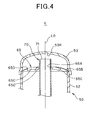
- Fig. 4 is a side sectional view showing the support member 65 together with the peripheral construction thereof
- Fig. 5 is a cross-sectional view of V-V of Fig. 2 , that is, shows the support member 65 together with the peripheral construction thereof from the upper side.
- the support member 65 has a through hole 65A at the center thereof, and the refrigerant lead-in pipe 60 penetrates through the through hole and is held there.
- the support member 65 is formed of a rigid member which evaginates upwardly (for example, like a dome) and is substantially disc-shaped. In this embodiment, it is formed of a mesh member obtained by knitting a wire rod such as a metal wire (for example, stainless wire or the like) having resistance to corrosion like a net.
- This support member 65 has a mesh-shaped cover member 65B which expands around the through hole 65A to cover the boundary between the body portion 52 of the oil separator main body 50 and the upper end plate 53, and plural cut and raised portions 65c formed in the mesh-shaped cover member 65B.
- the outer diameter of the mesh-shaped cover member 65B is set to such a value that the mesh-shaped cover member can be sandwiched between the body portion 52 of the oil separator main body 50 and the end plate 53 (the outer diameter of the mesh-shaped cover member 65B is between the inner and outer diameters of the body portion 52). That is, the mesh-shaped cover member 65B is put on the upper end face of the body portion 52, and the upper end plate 53 is covered on the upper end face of the body portion 52, whereby the outer peripheral edge of the mesh-shaped cover member 65B is sandwiched between the body portion 52 and the upper end plate 53. Accordingly, the support member 65 can be easily supported in the oil separator main body 50 without moving the support member 65 in the up-and-down direction and right-and-left direction.
- the mesh-shaped cover member 65B is designed to be upwardly convexed around the axial line L0, and thus has a convex shape, whereby the strength of the support member 65 can be more enhanced as compared with a case where it is designed to be flat.
- the enhancement of the strength of the support member 65 can ensure sufficient support strength of the support member 65 to the oil separator main body 50, and also sufficient support strength of the gas refrigerant lead-out pipe 70 to the support member 65 can be ensure.
- the upward convex shape as described above increases the surface area of the mesh-shaped cover member 65B.
- the mesh-shaped cover member 65B functions as a filter for passing gas refrigerant therethrough to the upper side and preventing other contents (oil, dust, etc. contained in refrigerant) frompassing therethrough, and thus the filter area canbe also increased by increasing the surface area of the mesh-shaped cover member 65B.
- the plural cut and raised portions 6C is formed integrally with the mesh-shaped cover member 65B by cutting and raising a part of the mesh-shaped cover member 65B downwardly. As described in detail, these cut and raised portions 65C are formed at a predetermined angular interval along the peripheral direction around the axial line L0. In this embodiment, they are formed at an angular interval of 22.5°, thereby forming eight cut and raised portions 65C.
- the cut and raised portions 65C are cut and raised so as to face the flow (the flow indicated by arrows in Fig. 5 ) of the refrigerant which is discharged from the gas refrigerant lead-in pipe 70 and flows along the inner peripheral surface of the oil separator main body 50, whereby the refrigerant is prevented from moving to the space above the support member 65.
- the mesh-shaped cover member 65B is cut and downwardly raised, and thus plural (eight in this embodiment) opening portions 65D opened in the vertical direction are formed at the cut and raised portions, so that upward flow of gas refrigerant in the oil separator main body 50 is not disturbed, and thus the gas refrigerant can be smoothly moved through the opening portions 65D into the space above the support member 65.
- Refrigerant discharged from the compressor while containing oil flows through the refrigerant lead-in pipe 60 into the upper area of the body portion 52 of the oil separator main body 50 in the oil separator 4 (see Fig. 2 ).
- the refrigerant discharged from the compressor 3 is high-pressure refrigerant, and also the refrigerant lead-in pipe 60 introduces the refrigerant along the inner peripheral surface of the body portion 52. Therefore, the refrigerant flows while swirling along the inner peripheral surface of the oil separator main body 50 (the flow indicated by an arrow of Fig. 3 ), and thus some of the refrigerant upwardly ascends while violently swirling.
- the oil contained in the refrigerant spatters outwardly in the radial direction by centrifugal force due to the difference in density between the refrigerant and the oil, whereby the gas refrigerant and the oil are separated from each other.
- the oil separator 4 is constructed as a so-called cyclone type oil separator for separating refrigerant and oil from each other by centrifugal separation.
- the gas refrigerant lead-out pipe 70 is disposed along the axial line L0 of the oil separator main body 50. Accordingly, the inner peripheral surface of the oil separator main body 50 and the outer peripheral surface of the gas refrigerant lead-out pipe 70 are disposed concentrically with each other (see Fig. 4 ), and the interval between the inner peripheral surface and the outer peripheral surface can be made uniform in the peripheral direction. Therefore, the passage width of an annular space in which the refrigerant swirls can be made uniform, and thus the flow of the refrigerant is not disturbed.
- the centrifugally separated oil is basically liquid. Therefore, it drops downwardly due to its own weight and pools at the bottom portion of the oil separator main body 50.
- the oil pooling at the bottom portion of the oil separator main body 50 is passed through an oil pipe 80 provided at the bottom portion, and returned to the suction side of the compressor 3.
- the gas refrigerant from which the oil is separated in the oil separator 4 is gas. Therefore, it flows to a higher side than the oil, passes through the support member 65, enters the space between the support member 65 and the upper end plate 53, enters the open end of the gas refrigerant lead-out pipe 70 which is upwardly opened in this space, and then is supplied to the four-way valve 5.
- the refrigerant discharged from the compressor is high-pressure refrigerant. Therefore, there is a case where the refrigerant which enters the oil separator main body 50 through the refrigerant lead-in pipe 60 impinges against the inner peripheral surface of the oil separator main body 50 and thus a part of the refrigerant (oil, dust, etc. other than the refrigerant) spatters upwardly, or there is a case where a part of the refrigerant spatters upwardly due to vigorous flow caused swirling in the oil separator main body 50.
- the oil separator is provided with the support member 65 covering the boundary portion between the upper end plate 53 and the body portion 52 of the oil separator main body 50, and the support member 65 is formed of the net-like mesh-shaped cover member 65B. Therefore, the support member 65 can be made to function as a filter for allowing only the gas refrigerant to pass upwardly therethrough and preventing the other contents (oil, dust, etc.) from passing therethrough.
- the plural cut and raised portions 65C are formed integrally with the mesh-shaped cover member 65B of the support member 65. Therefore, the refrigerant is guided downwardly by the cut and raised portions 65C and thus the oil, etc. can be prevented from moving upwardly. Furthermore, the vertically-penetrating opening portions 65D are formed by forming the cut and raised portions 65C. Therefore, even when the mesh-shaped cover member 65B clogs due to long-term use or the like, the passage route of the gas refrigerant can be continually ensured, and the lifetime of the oil separator 4 can be increased.
- the refrigerant lead-in pipe 60 is secured to the upper area of the body portion 52 so as to extend along the tangential direction of the body portion 52, and the pipe line thereof is designed so as to be opened to face the inner peripheral surface of the body portion 52.
- the support member 65 is provided at the inside of the boundary between the upper end plate 53 and the body portion 52.
- the gas refrigerant lead-out pipe 70 penetrates through the lower end plate 54, extends along the axial line L0 of the body portion 52, and penetrates through the support member 65 while supported by the support member 65, and the pipe line of the gas refrigerant lead-out pipe 70 is opened to face the top surface (inner surface) 53H of the upper end plate 53 and serve as the refrigerant gas take-in port. Accordingly, the lower portion of the gas refrigerant lead-out pipe 70 is supported by the lower end plate 54, and also the upper portion of the gas lead-out pipe 70 is supported by the support member 65 between the upper end plate 53 and the body portion 52, whereby the gas refrigerant lead-out pipe 70 can be supported at both the ends thereof.
- the lead-out pipe 70 must be designed to be long so that it is drawn out from the lower portion of the oil separator, the sufficient support strength of the gas refrigerant lead-out pipe 70 can be ensured, and the situation that coremisalignment or the like occurs due to impact, engine vibration or the like during transport can be surely prevented.
- the gas refrigerant lead-out pipe 70 penetrate through the lower end plate 54, extends along the axial line L0 of the body portion 52, penetrates through the support member 65 while supported by the support member 65, and is opened to face the top surface (inner surface) 53H of the upper end plate and serve as the refrigerant gas take-in port. Therefore, the annular space having an uniform width in which the refrigerant discharged from the refrigerant exit of the refrigerant lead-in pipe 60 swirls can be continuously ensured, and also oil, dust, etc. other than upwardly-ascending gas refrigerant can be prevented from entering the gas refrigerant lead-out pipe 70, so that the oil separation performance can be enhanced.
- the gas refrigerant lead-out pipe 70 is drawn out from the lower portion of the oil separator, and the sufficient oil separation performance ca be ensured.
- the height difference between the refrigerant gas take-in port 71 of the gas refrigerant lead-out pipe 70 (or the support member 60) and the opening portion 62 serving as the refrigerant discharge port of the refrigerant lead-in pipe 60 is set to such a proper distance that the refrigerant discharged from the opening portion 62 can be centrifugally separated above the opening portion 62 to some degree and also upwardly spattering oil, dust, etc. can be prevented from invading into the take-in port 71.
- This distance can be easily adjusted by changing the securing position of the refrigerant lead-in pipe 60 to the body portion 52 or the like.
- refrigerant flowing from the refrigerant lead-in pipe 60 flows into the annular space between the inner peripheral surface of the body portion 52 and the outer peripheral surface of the refrigerant flow-in pipe 60, and centrifugal force is applied to the refrigerant concerned, so that the oil and the refrigerant are separated from each other. Therefore, the oil and the refrigerant can be efficiently separated from each other by centrifugal separation.
- the support member 65 has the mesh-shaped cover member 65B covering the boundary between the upper end plate 53 and the body portion 52 and the cut and raised portions 65C obtained by cutting and downwardly raising a part of the mesh-shaped cover member 65B. Therefore, the upward movement of contents contained in the refrigerant other than the gas refrigerant can be interrupted by the mesh-shaped cover portion 65B. In addition, even when the mesh-shaped cover member 65B clogs, the passage route through which the gas refrigerant passes can be ensured by the opening portions 65D opened by the cut and raised portions 65C can be ensured. Furthermore, the upward movement of the contents other than the gas refrigerant can be also interrupted by the cut and raised portions 65C, so that the filter performance of the support member 65 can be enhanced.
- both the refrigerant lead-in pipe 60 and the gas refrigerant lead-out pipe 70 of the oil separator 4 are disposed at the upper portion of the oil separator, the pipes are concentrated in the upper space.
- the refrigerant lead-in pipe 60 and the gas refrigerant lead-out pipe 70 are disposed while sorted to the upper and lower sides. Therefore, layout of pipes can be performed without concentrating the locating positions of the pipes.
- it is effective to separately dispose the pipes at the upper and lower sides in consideration of the weight balance of the oil separator 4 as a single body.
- Fig. 6 is a side view of the oil separator 400 of the second embodiment.
- Fig. 7 is a III-III cross-sectional view of fig. 6
- Fig. 8 is a IV-IV cross-sectional view of Fig. 6 .
- the basic construction of the oil separator 400 is the same as the oil separator 4 of the first embodiment, and thus different constructions will be mainly described hereunder.
- the refrigerant lead-in pipe 60 is secured to the upper end plate 53, thereby forming a pipe line for introducing refrigerant from the upper side of the oil separator 400 into the upper portion inside the oil separator main body 50.
- the refrigerant lead-in pipe 60 straightly penetrates through the upper end plate 53 along the tangential direction of the wall of the upper end plate 53 and one end side thereof is opened in the neighborhood of a predetermined area of the inner peripheral surface of the end plate 53 in top view.
- the refrigerant lead-in pipe 60 is fixed to the upper end plate 53 so as to penetrate through the end plate 53 substantially in the horizontal direction in side view.
- the refrigerant lead-in pipe 60 avoids the axial line L0 of the oil separator main body 50 (which is coincident with the axial line of the body portion 52) and is disposed in the neighborhood of the inner peripheral surface of the upper end plate 53, whereby high-pressure refrigerant (refrigerant containing oil) discharged from the compressor 3 can be introduced along the inner peripheral surface of the end plate 53 into the oil separator main body 50.
- the opening portion 62 of the refrigerant lead-in pipe 60 inside the end plate 53 is obliquely cut in top view so that the opening edge 60A of the opening portion 62 which is nearer to the axial line L0 is longer in pipe length than the opening edge 60B of the opening portion 62 which is farther from the axial line L0 (nearer to the inner surface of the body portion 52), whereby the opening portion 62 of the refrigerant lead-in pipe 60 is oriented along the inner peripheral surface of the body portion 52.
- the refrigerant lead-in pipe 60 when refrigerant is discharged from the refrigerant lead-in pipe 60, the refrigerant does not spread to the axial line L0 side, and the refrigerant can be introduced into the oil separator main body 50 along the inner peripheral surface of the end plate 63. Furthermore, at the outside (upstream side) of the end plate 53, the refrigerant lead-in pipe 60 is upwardly bent to be substantially L-shaped as shown in Fig. 7 , and it can be connected to the discharge side of the compressor 3 at the upper side of the oil separator 400.
- the gas refrigerant lead-out pipe 70 is a pipe for leading out from the lower portion of the oil separator 4 gas refrigerant from which oil is separated in the oil separator main body 50. As shown in Figs. 6 and 7 , the gas refrigerant lead-out pipe 70 upwardly penetrates through the lower end plate 54 from the just lower side of the oil separator main body 50, extends along the axial line L0 of the body portion 52 until it abuts against the inner surface of the upper end plate 53, and is closed in pipe line by the top surface (inner surface) 53H of the upper end plate 53.
- plural (two in this embodiment) refrigerant lead-out holes (opening portions) 72 for leading out refrigerant gas into the gas refrigerant lead-out pipe 70 are formed substantially in the center area of the vertically-extending gas refrigerant lead-out pipe 70 in the oil separator main body 50 so as to be located at an angular interval of 180°, and also a cap member 75 is fixed to the gas refrigerant lead-out pipe 70 so as to surround the refrigerant gas lead-out holes 72.
- This cap member 75 is fixed while the gas refrigerant lead-out pipe 70 is inserted in the cap member 75. It is designed in such a cap-like (umbrella-like) shape as to annularly extend in the peripheral direction around the axial line (coincident with the axial line L0) of the gas refrigerant lead-out pipe 70 under this state (see Fig. 8 ), the inner diameter 75A of the upper portion of the cap member 75 is set to the same diameter as the outer diameter of the gas refrigerant lead-out 70, and thus the cap member 75 is supported by the gas refrigerant lead-out pipe 70 under the state that no gap exists between the cap member 75 and the gas refrigerant lead-out pipe 70.
- the cap member has such a diameter expansion shape that the diameter thereof is gradually increased toward the lower side thereof in side view. Accordingly, the gap between the outer surface of the cap member 75 and the inner peripheral surface of the oil separator main body 50 (the inner peripheral surface of the body portion 52) is gradually narrowed.
- the oil pipe 80 is a pipe for leading out the oil pooled in a lower area in the oil separator main body 50 from the lower portion of the oil separator 4, and a pipe which is remarkably small in diameter than the gas refrigerant lead-out pipe 70 is applied as the oil pipe 80 as shown in Figs. 6 and 8 .
- This oil pipe 80 penetrates through the lower end plate 54 so as to extend from the lower side to the upper side at a position far away from the gas refrigerant lead-out pipe 70, and it is fixed to the oil separator main body 50 while the upper end thereof is opened in the oil separator 50.
- Refrigerant containing oil which is discharged from the compressor 3 is flows into the upper end plate 53 of the oil separator main body 50 through the refrigerant lead-in pipe 60.
- the refrigerant discharged from the compressor 3 is high-pressure refrigerant, and the refrigerant is introduced along the inner peripheral surface of the end plate 53 by the refrigerant lead-in pipe 60. Therefore, the refrigerant flows while swirling along the inner peripheral surface of the oil separator main body 50 (the flow indicated by an arrow of Fig. 8 ), and thus it falls in the direction of gravitational force (downward) while violently swirling.
- the oil separator 400 is constructed as a so-called cyclone type oil separator for separating refrigerant and oil from each other by centrifugal separation.
- the gas refrigerant lead-out pipe 70 is disposed along the axial line L0 of the oil separator main body 50. Accordingly, the inner peripheral surface of the oil separator main body 50 and the outer peripheral surface of the gas refrigerant lead-out pipe 70 are disposed concentrically with each other (see Fig. 8 ), and the interval between the inner peripheral surface and the outer peripheral surface can be made uniform in the peripheral direction. Therefore, the passage width of an annular space in which the refrigerant swirls can be made uniform, and thus the flow of the refrigerant is not disturbed.
- the annular space (corresponding swirling passage) is narrowed in width along the outer peripheral surface of the cap member 75, so that the flow rate is increased by the amount corresponding to thenarrowedamount, and thus the centrifugal separationcanbepromoted. Furthermore, the cap member 75 covers the refrigerant lead-out holes 72 formed in the gas refrigerant lead-out pipe 70 from the upper side, and thus it can surely prevent the situation that refrigerant and oil spattered at the upper side of the cap member 75 directly enter the refrigerant'lead-out holes 72.
- the situation that the oil at the upper side of the cap member 75 enters the gas refrigerant lead-out pipe 70 can be prevented by the cap member 75, and also the situation that the oil at the lower side of the cap member 75 can be also prevented because the liquid oil hardly flow upwardly. Accordingly, the separated oil pools at the bottom portion of the oil separator main body 50, and it is passed through the oil pipe 80 provided at the bottom portion and returned to the suction side of the compressor 3.
- the gas refrigerant from which the oil is separated in the oil separator 400 is gas. Therefore, after the gas refrigerant flows downwardly to the lower side of the cap member 75, it easily flows upwardly and enters the cap member 75, so that the gas refrigerant can be passed through the lead-out holes 72 into the gas refrigerant lead-out pipe 70, and then supplied to the four-way valve 5.
- the refrigerant lead-in pipe 60 is secured to the upper end plate 53 so as to extend along the tangential direction of the upper end plate 53, and opened to the inner peripheral face of the end plate 53. Furthermore, the gas refrigerant lead-out pipe 70 penetrates through the lower end plate 54, extends along the axial line L0 of the body portion 52, and fixed to the top surface 53H as the inner peripheral surface of the upper end plate 53 while the pipe line thereof is closed by the top surface 53H.
- the refrigerant lead-out pipe 70 is provided with the refrigerant gas lead-out holes 72 substantially at the center portion thereof, and the lead-out holes 72 are surrounded by the cap member 75 fixed to the outer peripheral portion of the lead-out pipe 70.
- the gas refrigerant lead-out pipe 70 can be supported at both the ends thereof in the vertical direction (i.e., has a so-called center impeller structure), and thus the sufficient support strength of the gas refrigerant lead-out pipe 70 can be ensured. Therefore, even when the gas refrigerant lead-out pipe 70 is drawn out from the lower side and thus the gas refrigerant lead-out pipe 70 must be designed to be long, the support strength of the gas refrigerant lead-out pipe 70 can be sufficiently ensured. Therefore, the situation that core misalignment occurs due to impact, engine vibration or the like during transport can be surely prevented.
- the situation that oil directly enters the lead-out holes 72 can be prevented by the cap member 75 for covering the lead-out holes 72 from the upper side, and also the annular space having uniform width in which refrigerant swirls can be continuously ensured between the refrigerant outlet port of the refrigerant lead-in pipe 60 and the lead-out holes 72, and the oil separation performance can be enhanced.
- the sufficient oil separation performance can be ensured while the gas refrigerant lead-out pipe 70 is drawn out from the lower side of the oil separator 4.
- the height of the lead-out holes 72 or the like is adjusted, whereby the annular space length in which refrigerant swirls can be easily adjusted and the distance suitable for oil separation can be easily ensured. Furthermore, this distance can be also finely adjusted.
- the refrigerant flowing from the refrigerant lead-in pipe 60 flows into the annular space between the inner peripheral surface of the body portion 52 and the outer peripheral surface of the refrigerant lead-in pipe 60 and centrifugal force is applied to the refrigerant, so that gas refrigerant and oil are separated from each other. Therefore, oil and gas refrigerant can be efficiently separated from each other by centrifugal separation.
- both the refrigerant lead-in pipe 60 and the gas refrigerant lead-out pipe 70 of the oil separator 4 are piped at the upper side of the oil separator 4, the pipes are concentrated in the upper space.
- the refrigerant lead-in pipe 60 and the gas refrigerant lead-out pipe 70 are disposed while sorted to the upper and lower sides. Therefore, layout of pipes can be performed without concentrating the locating positions of the pipes.
- it is effective to separately dispose the pipes at the upper and lower sides in consideration of the weight balance of the oil separator 4 as a single body.
- the lead-out holes 72 are formed in the center area of the gas refrigerant lead-out pipe 70 so as to face each other.
- the formation position of the lead-out holes 72 is not necessarily set so that the lead-out holes 72 face each other.
- the lead-out holes 72 may be formed at any area other than the center area or they may be formed with setting a height difference therebetween insofar as foreign materials such as oil, dust, etc. can be prevented from invading into the lead-out holes 72.
- the present invention is not limited to the above-described embodiments, and various modifications and alterations can be made on the basis of the technical idea of the present invention.
- the present invention is applied to the oil separator used in the gas heat pump (GHP) type air conditioner.
- GFP gas heat pump
- the present invention is not limited to this type, but may be applied to an oil separator used in another type air conditioner or the like.
- each of the gas refrigerant take-in port (71) and the gas refrigerant lead-out holes 72 is independently provided to the gas refrigerant lead-out pipe 70.
- both the gas refrigerant take-in port (71) and the gas refrigerant lead-out pipes 72 may be provided to such an oil separator main body 50 as shown in Fig. 2 .
- the cap member is preferably provided at the lower side of the opening portion 62 of the refrigerant lead-in pipe 60.
Landscapes
- Engineering & Computer Science (AREA)
- Chemical & Material Sciences (AREA)
- Analytical Chemistry (AREA)
- Power Engineering (AREA)
- Physics & Mathematics (AREA)
- Mechanical Engineering (AREA)
- Thermal Sciences (AREA)
- General Engineering & Computer Science (AREA)
- Compressor (AREA)
- Applications Or Details Of Rotary Compressors (AREA)
Abstract
Description
- The present invention relates to an oil separator for separating oil in refrigerant.
- A refrigerant circuit of an air conditioner or the like has an oil separator, and oil contained in refrigerant discharged from a compressor is separated from the refrigerant by using this oil separator.
- This type oil separator is generally constructed so that refrigerant containing oil is made to flow from the side of the oil separator into the oil separator to separate the oil from the refrigerant and the separated oil is discharged from the lower portion of the oil separator while the separated gas refrigerant is discharged from the upper portion of the oil separator (see
JP-A-2008-101831 JP-A-Hei-5-296610 - In the oil separator as described above, a lead-out pipe for leading out the separated gas refrigerant to the outside is provided to the upper portion of the oil separator, so that a piping space is required to be provided at the upper side of the oil separator. On the other hand, there is a case where some layout of an air conditioner needs to draw a lead-out pipe for separated gas refrigerant out of the lower portion of the oil separator. For example, there is a case where the lead-out pipe must be piped and connected from the lower portion of the oil separator to a four-way valve as a connection destination of the lead-out pipe in consideration of the structure of the four-way valve.
- When the installation position of the lead-out pipe for the separated gas refrigerant is shifted from the upper portion of the oil separator to the lower portion of the oil separator, the lead-out pipe is required to extend upwardly to some degree in the oil separator because some level of oil pool (stock) must be secured at the inner lower portion of the oil separator. Accordingly, when the oil separator is transported, vibration under the transport may induce core misalignment to the lead-out pipe, so that it may be impossible to secure sufficient oil separation performance.
- Therefore, the present invention has an object to provide an oil separator which enables a lead-out pipe for gas refrigerant to be drawn out from the lower portion of the oil separator and also can secure the separation performance of oil and prevent core misalignment of the lead-out pipe for the gas refrigerant.
- In order to attain the above object, according to the present invention, an oil separator (4) that separates oil contained in refrigerant discharged from a compressor (3) and has an oil separator main body (50) comprising a body portion (52) and upper and lower end plates (53, 54) secured to both the ends of the body portion (52), the oil separator main body being vertically installed in an erected state, is characterized by further comprising: a refrigerant lead-in pipe (60) that is secured to the oil separator main body so as to extend along a tangential direction of the inner peripheral surface of the oil separator main body and opened at one end thereof so that the opened one end of the refrigerant lead-in pipe faces the inner peripheral surface of the oil separator main body; and a gas refrigerant lead-out pipe (70) that penetrates through the lower end plate (54) in the vertical direction of the oil separator main body and extends along an axial line of the oil separator main body while one end portion thereof is supported by the lower endplate (54), wherein a refrigerant gas lead-out opening portion (71, 72) for taking in gas refrigerant from which oil is separated in the oil separator main body is provided at at least one of a center area of the gas refrigerant lead-in pipe and the other end portion of the gas refrigerant lead-out pipe at the upper end plate (53) side.
- The above oil separator according to
claim 1 may further comprise a support member (65) having a through hole (65A) through which the one endportion of the gas refrigerant lead-out pipe penetrates, wherein the support member is provided at the inside of the boundary between the upper end plate and the body portion, the refrigerant lead-in pipe is secured to an upper area of the body portion so as to extend along a tangential direction of the inner peripheral surface of the body portion, and the one end of the refrigerant lead-in pipe is opened to face the inner peripheral surface of the body portion. - In the above oil separator, the refrigerant gas lead-out opening portion corresponds to the opened one end (71) of the refrigerant gas lead-out pipe (70) at the upper end plate side.
- In the above oil separator, an annular space in which centrifugal force is applied to the refrigerant flowing from the refrigerant lead-in pipe while the refrigerant swirls in the annular space is formed between the innerperipheral surface of thebodyportion and the outerperipheral surface of the refrigerant lead-out pipe, the oil and the gas refrigerant are separated from each other in the annular space by the centrifugal force concerned, the separated oil pools in a lower area of the body portion, and the separated gas refrigerant moves upward in the annular space, passes through the support member (65), and flows through the opening portion (71) into the refrigerant lead-out pipe, whereby the gas refrigerant is led out to the lower side of the oil separator main body.
- The oil separator may further comprises an oil pipe (80) that penetrates from the inside of the oil separator main body through the lower end plate and extends to the outside of the oil separator main body, wherein the oil pooling in the lower area of the body portion is passed through the oil pipe and led out to the lower side of the oil separator main body.
- In the above oil separator, the support member (65) comprises a mesh-shaped cover member (65B) covering the boundary between the upper end plate and the body portion and cut and raised portions (65D) obtained by cutting and raising a part of the mesh-shaped cover member downwardly.
- In the above oil separator, the refrigerant lead-in pipe is secured to the upper end plate so as to extend along a tangential direction of the inner peripheral surface of the upper end plate, the one end of the refrigerant lead-in pipe is opened to face the inner peripheral surface of the upper end plate, the gas refrigerant lead-out pipe is fixed to the upper end plate while the opened one end of the gas refrigerant lead-out pipe is closed by the inner surface of the upper end plate, and the refrigerant gas lead-out opening portion (72) is provided in the center area of the refrigerant lead-out pipe.
- In the above oil separator, the refrigerant gas lead-out opening portion (72) comprises plural gas refrigerant lead-out holes (72), and a cap member (75) is fixed to the outer peripheral portion of the refrigerant gas lead-out pipe so as to cover the gas refrigerant lead-out holes.
- In the above oil separator, an annular space in which centrifugal force is applied to the refrigerant flowing from the refrigerant lead-in pipe while the refrigerant swirls in the annular space is formed between the inner peripheral surface of the body portion and the outer peripheral surface of the refrigerant lead-out pipe, the oil and the gas refrigerant are separated from each other in the annular space by the centrifugal force concerned, the separated oil pools in a lower area of the body portion, and the separated gas refrigerant flows through the opening portion covered by the cap member into the refrigerant gas lead-out pipe, whereby the refrigerant gas is led out to the lower side of the oil separator main body.
- The oil separator may further comprise an oil pipe (80) that penetrates from the inside of the oil separator main body through the lower end plate and extends to the outside of the oil separator main body, wherein the oil pooling in the lower area of the body portion is passed through the oil pipe and led out to the lower side of the oil separator main body.
- According to the present invention, the oil separator main body comprises the body portion and the upper and lower end plates and is disposed in an erected state. The refrigerant lead-in pipe is secured to the upper area of the body portion along the tangential direction of the body portion, and one end thereof is opened to face the inner peripheral surface of the body portion. The support member is provided at the inside of the boundary between the upper end plate and the body portion, the gas refrigerant lead-out pipe penetrates through the lower end plate while supported at one end portion thereof by the lower end plate, extends along the axial line of the body portion in the oil separator, penetrates through the upper end plate while supported at the other end portion thereof by the upper end plate, and opened at one end thereof so as to face the inner surface of the upper end plate, thereby serving as the refrigerant gas take-in port. Therefore, the refrigerant gas lead-out pipe can be supported at both the end portions thereof in the vertical direction, and also oil, dust, etc. other than upwardly-ascending gas refrigerant can be prevented from invading into the gas refrigerant lead-out pipe.
- Furthermore, oil and gas refrigerant can be efficiently separated from each other by centrifugal separation, and thus the oil separation performance can be enhanced. Still furthermore, the oil separation performance can be ensured and the core misalignment of the gas refrigerant lead-out pipe can be prevented even when the gas refrigerant lead-out pipe can be drawn out from the lower side of the oil separator.
- In addition, the upward movement of foreign materials other than the gas refrigerant can be prevented by the mesh-shaped cover member and the cut and raised portions, and even when the mesh-shaped cover member clogs, the passing path through which the gas refrigerant can pass can be ensured by the opening portions which are generated by the cut and raised portions.
- Still furthermore, according to the present invention, the oil separator main body comprises the body portion and the upper and lower end plates and is disposed in an erected state, and the refrigerant lead-in pipe is secured to the upper end plate so as to extend along the tangential direction of the inner peripheral surface of the upper end plate, and one end of the refrigerant lead-in pipe is opened to face the inner peripheral surface of the end plate. The gas refrigerant lead-out pipe penetrates through the lower end plate while one end portion thereof is supported by the lower end plate, extends along the axial line of the body portion, and one end of the gas refrigerant lead-out pipe is fixed to the inner surface of the upper end plate while closed by the inner surface of the upper end plate, whereby the gas refrigerant lead-out pipe is supported at the other end portion thereof by the upper end plate. Accordingly, the gas refrigerant lead-out pipe can be supported at both the end portions thereof by the upper and lower end plates. The gas refrigerant lead-out pipe is equipped with the gas refrigerant lead-out holes in the center area thereof, and the cap member is fixed to the gas refrigerant lead-out pipe so as to surround (cover) the gas refrigerant lead-out holes. Accordingly, oil and gas refrigerant can be efficiently separated from each other by centrifugal separation, and the oil can be prevented from directly invading into the gas refrigerant lead-out holes by the cap member. Therefore, the oil separation performance can be ensured and the core misalignment of the gas refrigerant lead-out pipe can be prevented even when the gas refrigerant lead-out pipe is drawn out from the lower side of the oil separator.
-
-
Fig. 1 is a diagram showing an air conditioner using an oil separator according to the present invention; -
Fig. 2 is a sectional side view of an oil separator according to a first embodiment of the present invention; -
Fig. 3 is a cross-sectional view of III-III ofFig. 2 ; -
Fig. 4 is a sectional side view of a support member together with the peripheral construction thereof; -
Fig. 5 is a cross-sectional view of V-V ofFig. 2 ; -
Fig. 6 is a side view of an oil separator according to a second embodiment of the present invention; -
Fig. 7 is a cross-sectional view of III-III ofFig. 6 ; and -
Fig. 8 is a cross-sectional view of IV-IV ofFig. 6 . - Preferred embodiments according to the present invention will be described hereunder with reference to the accompanying drawings.
-
Fig. 1 is a diagram showing an embodiment of an air conditioner using an oil separator according to the present invention.Fig. 1 also shows the internal circuit construction of anoutdoor unit 100 used in a gas heat pump (GHP) type air conditioner. InFig. 1 , the air conditioner of this embodiment contains arefrigerant circuit 110 represented by a solid line and acooling water circuit 120 represented by a heavy solid line. Here, GHP means that a compressor is driven by a gas engine. - The
refrigerant circuit 110 of theoutdoor unit 100 contains agas engine 1, a compressor 3 connected to thegas engine 1 through aV belt 2, anoil separator 4, a four-way valve 5, anoutdoor heat exchanger 6 cooled by air sucked byfans 17, an electrically-drivenvalve 7, aplate heat exchanger 36 and anaccumulator 11 which are connected to one another from the compressor 3 through a refrigerant pipe in a clockwise direction, and theaccumulator 11 is connected to the compressor, whereby refrigerant is circulated in therefrigerant circuit 110. An indoor unit (not shown) is provided at the left side ofFig. 1 , and the refrigerant pipe is connected to the indoor unit through opening/closing valves - Furthermore, solid-line arrows in
Fig. 1 represent the flow of refrigerant in a refrigeration (cooling) cycle, and dashed-line arrows inFig. 1 represent the flow of refrigerant in a heating cycle. By switching the four-way valve 5, the cooling/heating operations can be switched to each other. - As shown in
Fig. 1 , therefrigerant circuit 110 is equipped with abypass valve 12 as an electrically-driven valve, aliquid valve 13 as an electrically-driven valve, apressure switch 14, a high-pressureside pressure sensor 15, a low-pressureside pressure sensor 16, acheck valve 18, asub cooler 19 and adry core 8. - The
cooling water circuit 120 in theoutdoor unit 100 contains a hot water three-way valve 37 (which is also called as an electrically-driven cooler three-way valve),a cooling water three-way valve 20, aradiator 39, an electrically-drivenvalve 40, areservoir tank 22 and acooling water pump 21 which are successively connected from thegas engine 1 through a cooling water pipe, and thecooing water pump 21 is connected to an exhaustgas heat exchanger 23 of thegas engine 1, whereby cooing water is circulated in thecooling water circuit 120.Reference numeral 38 represents a buffer tank connected to the exhaustgas heat exchanger 23. Furthermore, anexhaust muffler 24 is connected to the exhaustgas heat exchanger 23, and anexhaust top 25 and adrain filter 26 are connected to theexhaust muffler 24. - As shown in
Fig. 1 , thegas engine 1 is connected to combustiongas shutoff valves 27, a zerogovernor 28, afuel adjusting valve 29 as an electrically-driven valve, anair cleaner 30, astepping motor 31, asub oil pan 32 containing anoil level switch 33, anoil pump 34 and anoil catcher 35. Gas as fuel is supplied into thegas engine 1 by the opening/closing operation of the combustiongas shutoff valve 27 and the motion of the steppingmotor 31. - In the
cooling water circuit 120, the heavy solid-line arrows inFig. 1 represent the flow of the cooling water under refrigeration cycle. During refrigeration cycle, the cooling water flowing out from thegas engine 1 flows through the hot water three-way valve 37 and the cooling water three-way valve 20, and further flows to theradiator 39 to be cooled. Then, the cooling water is passed through the electrically-drivenvalve 40, and pumped back to the coolingwater pump 21. - The dashed-line arrows in
Fig. 1 represent the flow of the cooling water during heating cycle. During heating cycle, a flow amount of 90% or more of cooling water flowing out from thegas engine 1 is pumped back from the hot-water three-way valve 37 to the coolingwater pump 21 by the coolingwater pump 21. - Next, the
oil separator 4 used in the air conditioner will be described. - The refrigerant discharged from the compressor 3 contains lubrication oil for the compressor 3. As shown in
Fig. 1 , theoil separator 4 is disposed at the discharge side of the compressor 3 in therefrigerant circuit 110. Theoil separator 4 separates the oil from the refrigerant which is discharged from the compressor 3 and contains the oil, returns the separated oil to the suction side of the compressor 3 and supplies the four-way valve 5 with gas refrigerant from which the oil is removed. -
Fig. 2 is a side sectional view of theoil separator 4, andFig. 3 is a cross-sectional view of III-III ofFig. 2 . As shown inFig. 2 , theoil separator 4 has an oil separator main body as a cylindrical container, arefrigerant introducing pipe 60 for introducing oil discharged from the compressor 3 into the oil separatormain body 50, a gas refrigerant lead-outpipe 70 for leading out gas refrigerant in the oil separatormain body 50 to the outside of theoil separator 4, and an oil pipe 80 (seeFig. 3 ) for leading out the oil in the oil separatormain body 50 to the outside of the oil separator. - The oil separator
main body 50 is provided with a pair of right andleft leg portions 51, and the oil separatormain body 50 is disposed in vertical position by theleg portions 51 so as to stand erect and be spaced from the ground plane (the bottom plate of the outdoor unit 100). - This oil separator
main body 50 is constructed by acylindrical body portion 52, and a pair of upper and lower end covers 53 and 54 which close the upper and lower openings of thebody portion 52. The pair of right andleft leg portions 51 are joined to the outer peripheral portion of theend cover 54 at the lower end by welding or the like. - The
refrigerant introducing pipe 60 is secured to an upper area of thebody portion 52, and introduces refrigerant from the upper side of theoil separator 4 into the upper portion of the inside of the oil separatormain body 50. As described in more detail, as shown inFig. 3 , therefrigerant introducing pipe 60 straightly penetrates through theend cover 53 along the tangent direction of the wall of thebody portion 52, and one end side thereof is opened at a position proximate to a predetermined area on the inner surface of theend cover 53. In side view, it is fixed to thebody portion 52 so as to penetrate through thebody portion 52 in a substantially horizontal direction as shown inFig. 2 . Accordingly, as shown inFig. 3 , the refrigerant lead-inpipe 60 is disposed in the neighborhood of the inner peripheral surface of thebody portion 52 so as to avoid the axial line L0 of the oil separator main body 50 (which is coincident with the axial line of the body portion 52), and leads high-pressure refrigerant (refrigerant containing oil) discharged from the compressor 3 along the inner peripheral surface of thebody portion 52 into the oil separatormain body 50. - Furthermore, one end portion (opening portion) 62 of the refrigerant lead-in
pipe 60 inside thebody portion 52 is designed to be downwardly inclined (as if it is obliquely cut) in top view so that the openingedge 60A of the openingportion 62 which is nearer to the axial line L0 is longer in pipe length than the openingedge 60B of the openingportion 62 which is farther from the axial line L0 (nearer to the inner surface of the body portion 52), whereby the openingportion 62 of the refrigerant lead-inpipe 60 is oriented along the inner peripheral surface of thebody portion 52. - Accordingly, when refrigerant is discharged from the refrigerant lead-in
pipe 60, the refrigerant does spread to the axial line L0 side, and thus the refrigerant can be introduced
into the oil separatormain body 50 while flowing along the inner peripheral surface of thebody portion 52. The exterior portion (upstream portion) of the refrigerant lead-inpipe 60 at the outside of thebody portion 52 is designed to be bent substantially in L-shape and then extend upwardly as shown inFig. 2 , whereby the refrigerant lead-inpipe 60 can be connected to the discharge side of the compressor 3 at the upper side of theoil separator 4. - The gas refrigerant lead-out
pipe 70 is a pipe for leading out from the lower portion of theoil separator 4 gas refrigerant from which oil is separated in the oil separatormain body 50. As shown inFig. 2 , the gas refrigerant lead-outpipe 70 upwardly penetrates through thelower end plate 54 from the just lower side of the oil separatormain body 50, extends along the axial line L0 of thebody portion 52, penetrates through asupport member 65 supported on the inner surface at the boundary between thebody portion 52 and theupper end plate 53 so as to be supported by thesupport member 65 and extends to the top surface (inner surface) 53H of theupper end plate 53. One opened end of the gas refrigerant lead-outpipe 70 at theupper end plate 53 serves as a refrigerant gas take-inport 71. - Here,
Fig. 4 is a side sectional view showing thesupport member 65 together with the peripheral construction thereof, andFig. 5 is a cross-sectional view of V-V ofFig. 2 , that is, shows thesupport member 65 together with the peripheral construction thereof from the upper side. - As shown in
Figs. 4 and5 , thesupport member 65 has a throughhole 65A at the center thereof, and the refrigerant lead-inpipe 60 penetrates through the through hole and is held there. Thesupport member 65 is formed of a rigid member which evaginates upwardly (for example, like a dome) and is substantially disc-shaped. In this embodiment, it is formed of a mesh member obtained by knitting a wire rod such as a metal wire (for example, stainless wire or the like) having resistance to corrosion like a net. - This
support member 65 has a mesh-shapedcover member 65B which expands around the throughhole 65A to cover the boundary between thebody portion 52 of the oil separatormain body 50 and theupper end plate 53, and plural cut and raised portions 65c formed in the mesh-shapedcover member 65B. - The outer diameter of the mesh-shaped
cover member 65B is set to such a value that the mesh-shaped cover member can be sandwiched between thebody portion 52 of the oil separatormain body 50 and the end plate 53 (the outer diameter of the mesh-shapedcover member 65B is between the inner and outer diameters of the body portion 52). That is, the mesh-shapedcover member 65B is put on the upper end face of thebody portion 52, and theupper end plate 53 is covered on the upper end face of thebody portion 52, whereby the outer peripheral edge of the mesh-shapedcover member 65B is sandwiched between thebody portion 52 and theupper end plate 53. Accordingly, thesupport member 65 can be easily supported in the oil separatormain body 50 without moving thesupport member 65 in the up-and-down direction and right-and-left direction. - Furthermore, the mesh-shaped
cover member 65B is designed to be upwardly convexed around the axial line L0, and thus has a convex shape, whereby the strength of thesupport member 65 can be more enhanced as compared with a case where it is designed to be flat. The enhancement of the strength of thesupport member 65 can ensure sufficient support strength of thesupport member 65 to the oil separatormain body 50, and also sufficient support strength of the gas refrigerant lead-outpipe 70 to thesupport member 65 can be ensure. - Furthermore, the upward convex shape as described above increases the surface area of the mesh-shaped
cover member 65B. As described later, the mesh-shapedcover member 65B functions as a filter for passing gas refrigerant therethrough to the upper side and preventing other contents (oil, dust, etc. contained in refrigerant) frompassing therethrough, and thus the filter area canbe also increased by increasing the surface area of the mesh-shapedcover member 65B. - The plural cut and raised portions 6C is formed integrally with the mesh-shaped
cover member 65B by cutting and raising a part of the mesh-shapedcover member 65B downwardly. As described in detail, these cut and raisedportions 65C are formed at a predetermined angular interval along the peripheral direction around the axial line L0. In this embodiment, they are formed at an angular interval of 22.5°, thereby forming eight cut and raisedportions 65C. - As shown in
Fig. 5 , the cut and raisedportions 65C are cut and raised so as to face the flow (the flow indicated by arrows inFig. 5 ) of the refrigerant which is discharged from the gas refrigerant lead-inpipe 70 and flows along the inner peripheral surface of the oil separatormain body 50, whereby the refrigerant is prevented from moving to the space above thesupport member 65. - Furthermore, the mesh-shaped
cover member 65B is cut and downwardly raised, and thus plural (eight in this embodiment) openingportions 65D opened in the vertical direction are formed at the cut and raised portions, so that upward flow of gas refrigerant in the oil separatormain body 50 is not disturbed, and thus the gas refrigerant can be smoothly moved through the openingportions 65D into the space above thesupport member 65. - Next, an oil separating operation of the
oil separator 4 will be described. - Refrigerant discharged from the compressor while containing oil flows through the refrigerant lead-in
pipe 60 into the upper area of thebody portion 52 of the oil separatormain body 50 in the oil separator 4 (seeFig. 2 ). The refrigerant discharged from the compressor 3 is high-pressure refrigerant, and also the refrigerant lead-inpipe 60 introduces the refrigerant along the inner peripheral surface of thebody portion 52. Therefore, the refrigerant flows while swirling along the inner peripheral surface of the oil separator main body 50 (the flow indicated by an arrow ofFig. 3 ), and thus some of the refrigerant upwardly ascends while violently swirling. - As a result, the oil contained in the refrigerant spatters outwardly in the radial direction by centrifugal force due to the difference in density between the refrigerant and the oil, whereby the gas refrigerant and the oil are separated from each other. That is, the
oil separator 4 is constructed as a so-called cyclone type oil separator for separating refrigerant and oil from each other by centrifugal separation. - In this case, in the
oil separator 4, the gas refrigerant lead-outpipe 70 is disposed along the axial line L0 of the oil separatormain body 50. Accordingly, the inner peripheral surface of the oil separatormain body 50 and the outer peripheral surface of the gas refrigerant lead-outpipe 70 are disposed concentrically with each other (seeFig. 4 ), and the interval between the inner peripheral surface and the outer peripheral surface can be made uniform in the peripheral direction. Therefore, the passage width of an annular space in which the refrigerant swirls can be made uniform, and thus the flow of the refrigerant is not disturbed. - The centrifugally separated oil is basically liquid. Therefore, it drops downwardly due to its own weight and pools at the bottom portion of the oil separator
main body 50. The oil pooling at the bottom portion of the oil separatormain body 50 is passed through anoil pipe 80 provided at the bottom portion, and returned to the suction side of the compressor 3. - On the other hand, the gas refrigerant from which the oil is separated in the
oil separator 4 is gas. Therefore, it flows to a higher side than the oil, passes through thesupport member 65, enters the space between thesupport member 65 and theupper end plate 53, enters the open end of the gas refrigerant lead-outpipe 70 which is upwardly opened in this space, and then is supplied to the four-way valve 5. - The refrigerant discharged from the compressor is high-pressure refrigerant. Therefore, there is a case where the refrigerant which enters the oil separator
main body 50 through the refrigerant lead-inpipe 60 impinges against the inner peripheral surface of the oil separatormain body 50 and thus a part of the refrigerant (oil, dust, etc. other than the refrigerant) spatters upwardly, or there is a case where a part of the refrigerant spatters upwardly due to vigorous flow caused swirling in the oil separatormain body 50. - According to this embodiment, the oil separator is provided with the
support member 65 covering the boundary portion between theupper end plate 53 and thebody portion 52 of the oil separatormain body 50, and thesupport member 65 is formed of the net-like mesh-shapedcover member 65B. Therefore, thesupport member 65 can be made to function as a filter for allowing only the gas refrigerant to pass upwardly therethrough and preventing the other contents (oil, dust, etc.) from passing therethrough. - In addition, the plural cut and raised
portions 65C are formed integrally with the mesh-shapedcover member 65B of thesupport member 65. Therefore, the refrigerant is guided downwardly by the cut and raisedportions 65C and thus the oil, etc. can be prevented from moving upwardly. Furthermore, the vertically-penetratingopening portions 65D are formed by forming the cut and raisedportions 65C. Therefore, even when the mesh-shapedcover member 65B clogs due to long-term use or the like, the passage route of the gas refrigerant can be continually ensured, and the lifetime of theoil separator 4 can be increased. - As described above, according to the
oil separator 4 of this embodiment, the refrigerant lead-inpipe 60 is secured to the upper area of thebody portion 52 so as to extend along the tangential direction of thebody portion 52, and the pipe line thereof is designed so as to be opened to face the inner peripheral surface of thebody portion 52. Thesupport member 65 is provided at the inside of the boundary between theupper end plate 53 and thebody portion 52. Furthermore, the gas refrigerant lead-outpipe 70 penetrates through thelower end plate 54, extends along the axial line L0 of thebody portion 52, and penetrates through thesupport member 65 while supported by thesupport member 65, and the pipe line of the gas refrigerant lead-outpipe 70 is opened to face the top surface (inner surface) 53H of theupper end plate 53 and serve as the refrigerant gas take-in port. Accordingly, the lower portion of the gas refrigerant lead-outpipe 70 is supported by thelower end plate 54, and also the upper portion of the gas lead-outpipe 70 is supported by thesupport member 65 between theupper end plate 53 and thebody portion 52, whereby the gas refrigerant lead-outpipe 70 can be supported at both the ends thereof. - Therefore, even when the lead-out
pipe 70 must be designed to be long so that it is drawn out from the lower portion of the oil separator, the sufficient support strength of the gas refrigerant lead-outpipe 70 can be ensured, and the situation that coremisalignment or the like occurs due to impact, engine vibration or the like during transport can be surely prevented. - In addition, the gas refrigerant lead-out
pipe 70 penetrate through thelower end plate 54, extends along the axial line L0 of thebody portion 52, penetrates through thesupport member 65 while supported by thesupport member 65, and is opened to face the top surface (inner surface) 53H of the upper end plate and serve as the refrigerant gas take-in port. Therefore, the annular space having an uniform width in which the refrigerant discharged from the refrigerant exit of the refrigerant lead-inpipe 60 swirls can be continuously ensured, and also oil, dust, etc. other than upwardly-ascending gas refrigerant can be prevented from entering the gas refrigerant lead-outpipe 70, so that the oil separation performance can be enhanced. - That is, in the thus-constructed
oil separator 4, the gas refrigerant lead-outpipe 70 is drawn out from the lower portion of the oil separator, and the sufficient oil separation performance ca be ensured. - Furthermore, the height difference between the refrigerant gas take-in
port 71 of the gas refrigerant lead-out pipe 70 (or the support member 60) and the openingportion 62 serving as the refrigerant discharge port of the refrigerant lead-inpipe 60 is set to such a proper distance that the refrigerant discharged from the openingportion 62 can be centrifugally separated above the openingportion 62 to some degree and also upwardly spattering oil, dust, etc. can be prevented from invading into the take-inport 71. This distance can be easily adjusted by changing the securing position of the refrigerant lead-inpipe 60 to thebody portion 52 or the like. - According to the above construction, refrigerant flowing from the refrigerant lead-in
pipe 60 flows into the annular space between the inner peripheral surface of thebody portion 52 and the outer peripheral surface of the refrigerant flow-inpipe 60, and centrifugal force is applied to the refrigerant concerned, so that the oil and the refrigerant are separated from each other. Therefore, the oil and the refrigerant can be efficiently separated from each other by centrifugal separation. - According to the above construction, the
support member 65 has the mesh-shapedcover member 65B covering the boundary between theupper end plate 53 and thebody portion 52 and the cut and raisedportions 65C obtained by cutting and downwardly raising a part of the mesh-shapedcover member 65B. Therefore, the upward movement of contents contained in the refrigerant other than the gas refrigerant can be interrupted by the mesh-shapedcover portion 65B. In addition, even when the mesh-shapedcover member 65B clogs, the passage route through which the gas refrigerant passes can be ensured by the openingportions 65D opened by the cut and raisedportions 65C can be ensured. Furthermore, the upward movement of the contents other than the gas refrigerant can be also interrupted by the cut and raisedportions 65C, so that the filter performance of thesupport member 65 can be enhanced. - When both the refrigerant lead-in
pipe 60 and the gas refrigerant lead-outpipe 70 of theoil separator 4 are disposed at the upper portion of the oil separator, the pipes are concentrated in the upper space. However, in this construction, the refrigerant lead-inpipe 60 and the gas refrigerant lead-outpipe 70 are disposed while sorted to the upper and lower sides. Therefore, layout of pipes can be performed without concentrating the locating positions of the pipes. Furthermore, when attention is paid to the stress which is applied to the pipes due to vibration of thegas engine 1, it is effective to separately dispose the pipes at the upper and lower sides in consideration of the weight balance of theoil separator 4 as a single body. - Next, an
oil separator 400 according to a second embodiment used in the air conditioner will be described. Constituent elements having substantially the same functions as the first embodiment are represented by the same reference numerals. -
Fig. 6 is a side view of theoil separator 400 of the second embodiment.Fig. 7 is a III-III cross-sectional view offig. 6 , andFig. 8 is a IV-IV cross-sectional view ofFig. 6 . - As shown in
Figs. 6 and7 , the basic construction of theoil separator 400 is the same as theoil separator 4 of the first embodiment, and thus different constructions will be mainly described hereunder. - In this embodiment, the refrigerant lead-in
pipe 60 is secured to theupper end plate 53, thereby forming a pipe line for introducing refrigerant from the upper side of theoil separator 400 into the upper portion inside the oil separatormain body 50. In detail, as shown inFig. 8 , the refrigerant lead-inpipe 60 straightly penetrates through theupper end plate 53 along the tangential direction of the wall of theupper end plate 53 and one end side thereof is opened in the neighborhood of a predetermined area of the inner peripheral surface of theend plate 53 in top view. Furthermore, as shown inFig. 7 , the refrigerant lead-inpipe 60 is fixed to theupper end plate 53 so as to penetrate through theend plate 53 substantially in the horizontal direction in side view. Accordingly, the refrigerant lead-inpipe 60 avoids the axial line L0 of the oil separator main body 50 (which is coincident with the axial line of the body portion 52) and is disposed in the neighborhood of the inner peripheral surface of theupper end plate 53, whereby high-pressure refrigerant (refrigerant containing oil) discharged from the compressor 3 can be introduced along the inner peripheral surface of theend plate 53 into the oil separatormain body 50. - The opening
portion 62 of the refrigerant lead-inpipe 60 inside theend plate 53 is obliquely cut in top view so that the openingedge 60A of the openingportion 62 which is nearer to the axial line L0 is longer in pipe length than the openingedge 60B of the openingportion 62 which is farther from the axial line L0 (nearer to the inner surface of the body portion 52), whereby the openingportion 62 of the refrigerant lead-inpipe 60 is oriented along the inner peripheral surface of thebody portion 52. - Accordingly, when refrigerant is discharged from the refrigerant lead-in
pipe 60, the refrigerant does not spread to the axial line L0 side, and the refrigerant can be introduced into the oil separatormain body 50 along the inner peripheral surface of the end plate 63. Furthermore, at the outside (upstream side) of theend plate 53, the refrigerant lead-inpipe 60 is upwardly bent to be substantially L-shaped as shown inFig. 7 , and it can be connected to the discharge side of the compressor 3 at the upper side of theoil separator 400. - The gas refrigerant lead-out
pipe 70 is a pipe for leading out from the lower portion of theoil separator 4 gas refrigerant from which oil is separated in the oil separatormain body 50. As shown inFigs. 6 and7 , the gas refrigerant lead-outpipe 70 upwardly penetrates through thelower end plate 54 from the just lower side of the oil separatormain body 50, extends along the axial line L0 of thebody portion 52 until it abuts against the inner surface of theupper end plate 53, and is closed in pipe line by the top surface (inner surface) 53H of theupper end plate 53. - In this embodiment, plural (two in this embodiment) refrigerant lead-out holes (opening portions) 72 for leading out refrigerant gas into the gas refrigerant lead-out
pipe 70 are formed substantially in the center area of the vertically-extending gas refrigerant lead-outpipe 70 in the oil separatormain body 50 so as to be located at an angular interval of 180°, and also acap member 75 is fixed to the gas refrigerant lead-outpipe 70 so as to surround the refrigerant gas lead-out holes 72. - This
cap member 75 is fixed while the gas refrigerant lead-outpipe 70 is inserted in thecap member 75. It is designed in such a cap-like (umbrella-like) shape as to annularly extend in the peripheral direction around the axial line (coincident with the axial line L0) of the gas refrigerant lead-outpipe 70 under this state (seeFig. 8 ), theinner diameter 75A of the upper portion of thecap member 75 is set to the same diameter as the outer diameter of the gas refrigerant lead-out 70, and thus thecap member 75 is supported by the gas refrigerant lead-outpipe 70 under the state that no gap exists between thecap member 75 and the gas refrigerant lead-outpipe 70. - Furthermore, as shown in
Fig. 7 , the cap member has such a diameter expansion shape that the diameter thereof is gradually increased toward the lower side thereof in side view. Accordingly, the gap between the outer surface of thecap member 75 and the inner peripheral surface of the oil separator main body 50 (the inner peripheral surface of the body portion 52) is gradually narrowed. - Furthermore, the
oil pipe 80 is a pipe for leading out the oil pooled in a lower area in the oil separatormain body 50 from the lower portion of theoil separator 4, and a pipe which is remarkably small in diameter than the gas refrigerant lead-outpipe 70 is applied as theoil pipe 80 as shown inFigs. 6 and8 . Thisoil pipe 80 penetrates through thelower end plate 54 so as to extend from the lower side to the upper side at a position far away from the gas refrigerant lead-outpipe 70, and it is fixed to the oil separatormain body 50 while the upper end thereof is opened in theoil separator 50. - Next, the oil separating operation of the
oil separator 400 will be described. - Refrigerant containing oil which is discharged from the compressor 3 is flows into the
upper end plate 53 of the oil separatormain body 50 through the refrigerant lead-inpipe 60. The refrigerant discharged from the compressor 3 is high-pressure refrigerant, and the refrigerant is introduced along the inner peripheral surface of theend plate 53 by the refrigerant lead-inpipe 60. Therefore, the refrigerant flows while swirling along the inner peripheral surface of the oil separator main body 50 (the flow indicated by an arrow ofFig. 8 ), and thus it falls in the direction of gravitational force (downward) while violently swirling. - As a result, the oil contained in the refrigerant spatters outwardly in the radial direction by centrifugal force due to the difference in density between the refrigerant and the oil, whereby the gas refrigerant and the oil are separated from each other. That is, the
oil separator 400 is constructed as a so-called cyclone type oil separator for separating refrigerant and oil from each other by centrifugal separation. - In this case, in the
oil separator 400, the gas refrigerant lead-outpipe 70 is disposed along the axial line L0 of the oil separatormain body 50. Accordingly, the inner peripheral surface of the oil separatormain body 50 and the outer peripheral surface of the gas refrigerant lead-outpipe 70 are disposed concentrically with each other (seeFig. 8 ), and the interval between the inner peripheral surface and the outer peripheral surface can be made uniform in the peripheral direction. Therefore, the passage width of an annular space in which the refrigerant swirls can be made uniform, and thus the flow of the refrigerant is not disturbed. - When the refrigerant falls to the position of the
cap member 75, the annular space (corresponding swirling passage) is narrowed in width along the outer peripheral surface of thecap member 75, so that the flow rate is increased by the amount corresponding to thenarrowedamount, and thus the centrifugal separationcanbepromoted. Furthermore, thecap member 75 covers the refrigerant lead-outholes 72 formed in the gas refrigerant lead-outpipe 70 from the upper side, and thus it can surely prevent the situation that refrigerant and oil spattered at the upper side of thecap member 75 directly enter the refrigerant'lead-out holes 72. - In short, with respect to the oil separated in the
oil separator 400, the situation that the oil at the upper side of thecap member 75 enters the gas refrigerant lead-outpipe 70 can be prevented by thecap member 75, and also the situation that the oil at the lower side of thecap member 75 can be also prevented because the liquid oil hardly flow upwardly. Accordingly, the separated oil pools at the bottom portion of the oil separatormain body 50, and it is passed through theoil pipe 80 provided at the bottom portion and returned to the suction side of the compressor 3. - On the other hand, the gas refrigerant from which the oil is separated in the
oil separator 400 is gas. Therefore, after the gas refrigerant flows downwardly to the lower side of thecap member 75, it easily flows upwardly and enters thecap member 75, so that the gas refrigerant can be passed through the lead-outholes 72 into the gas refrigerant lead-outpipe 70, and then supplied to the four-way valve 5. - As described above, in the
oil separator 400 of this embodiment, the refrigerant lead-inpipe 60 is secured to theupper end plate 53 so as to extend along the tangential direction of theupper end plate 53, and opened to the inner peripheral face of theend plate 53. Furthermore, the gas refrigerant lead-outpipe 70 penetrates through thelower end plate 54, extends along the axial line L0 of thebody portion 52, and fixed to thetop surface 53H as the inner peripheral surface of theupper end plate 53 while the pipe line thereof is closed by thetop surface 53H. The refrigerant lead-outpipe 70 is provided with the refrigerant gas lead-outholes 72 substantially at the center portion thereof, and the lead-outholes 72 are surrounded by thecap member 75 fixed to the outer peripheral portion of the lead-outpipe 70. Therefore, the gas refrigerant lead-outpipe 70 can be supported at both the ends thereof in the vertical direction (i.e., has a so-called center impeller structure), and thus the sufficient support strength of the gas refrigerant lead-outpipe 70 can be ensured. Therefore, even when the gas refrigerant lead-outpipe 70 is drawn out from the lower side and thus the gas refrigerant lead-outpipe 70 must be designed to be long, the support strength of the gas refrigerant lead-outpipe 70 can be sufficiently ensured. Therefore, the situation that core misalignment occurs due to impact, engine vibration or the like during transport can be surely prevented. - Furthermore, the situation that oil directly enters the lead-out
holes 72 can be prevented by thecap member 75 for covering the lead-outholes 72 from the upper side, and also the annular space having uniform width in which refrigerant swirls can be continuously ensured between the refrigerant outlet port of the refrigerant lead-inpipe 60 and the lead-outholes 72, and the oil separation performance can be enhanced. - That is, in the
oil separator 4 of this construction, the sufficient oil separation performance can be ensured while the gas refrigerant lead-outpipe 70 is drawn out from the lower side of theoil separator 4. In this case, the height of the lead-outholes 72 or the like is adjusted, whereby the annular space length in which refrigerant swirls can be easily adjusted and the distance suitable for oil separation can be easily ensured. Furthermore, this distance can be also finely adjusted. - In the above construction, the refrigerant flowing from the refrigerant lead-in
pipe 60 flows into the annular space between the inner peripheral surface of thebody portion 52 and the outer peripheral surface of the refrigerant lead-inpipe 60 and centrifugal force is applied to the refrigerant, so that gas refrigerant and oil are separated from each other. Therefore, oil and gas refrigerant can be efficiently separated from each other by centrifugal separation. - Furthermore, when both the refrigerant lead-in
pipe 60 and the gas refrigerant lead-outpipe 70 of theoil separator 4 are piped at the upper side of theoil separator 4, the pipes are concentrated in the upper space. However, according to this embodiment, the refrigerant lead-inpipe 60 and the gas refrigerant lead-outpipe 70 are disposed while sorted to the upper and lower sides. Therefore, layout of pipes can be performed without concentrating the locating positions of the pipes. Furthermore, when attention is paid to the stress which is applied to the pipes due to vibration of thegas engine 1, it is effective to separately dispose the pipes at the upper and lower sides in consideration of the weight balance of theoil separator 4 as a single body. - In this embodiment, the lead-out
holes 72 are formed in the center area of the gas refrigerant lead-outpipe 70 so as to face each other. However, the formation position of the lead-outholes 72 is not necessarily set so that the lead-outholes 72 face each other. The lead-outholes 72 may be formed at any area other than the center area or they may be formed with setting a height difference therebetween insofar as foreign materials such as oil, dust, etc. can be prevented from invading into the lead-out holes 72. - The present invention is not limited to the above-described embodiments, and various modifications and alterations can be made on the basis of the technical idea of the present invention. For example, in these embodiments, the present invention is applied to the oil separator used in the gas heat pump (GHP) type air conditioner. However, the present invention is not limited to this type, but may be applied to an oil separator used in another type air conditioner or the like.
- In the above embodiments, each of the gas refrigerant take-in port (71) and the gas refrigerant lead-out
holes 72 is independently provided to the gas refrigerant lead-outpipe 70. However, both the gas refrigerant take-in port (71) and the gas refrigerant lead-outpipes 72 may be provided to such an oil separatormain body 50 as shown inFig. 2 . In this case, the cap member is preferably provided at the lower side of the openingportion 62 of the refrigerant lead-inpipe 60.
Claims (10)
- An oil separator (4) that separates oil contained in refrigerant discharged from a compressor (3) and has an oil separator main body (50) comprising a body portion (52) and upper and lower end plates (53, 54) secured to both the ends of the body portion (52), the oil separator main body being vertically installed in an erected state, characterized by further comprising:a refrigerant lead-in pipe (60) that is secured to the oil separator main body so as to extend along a tangential direction of the inner peripheral surface of the oil separator main body and opened at one end thereof so that the opened one end of the refrigerant lead-in pipe faces the inner peripheral surface of the oil separator main body; anda gas refrigerant lead-out pipe (70) that penetrates through the lower end plate (54) in the vertical direction of the oil separator main body and extends along an axial line of the oil separator main body while one end portion thereof is supported by the lower end plate (54), wherein a refrigerant gas lead-out opening portion (71, 72) for taking in gas refrigerant from which oil is separated in the oil separator main body is provided at at least one of a center area of the gas refrigerant lead-in pipe and the other end portion of the gas refrigerant lead-out pipe at the upper end plate (53) side.
- The oil separator according to claim 1, further comprising a support member (65) having a through hole (65A) through which the one end portion of the gas refrigerant lead-out pipe penetrates, wherein the support member is provided at the inside of the boundary between the upper end plate and the body portion, the refrigerant lead-in pipe is secured to an upper area of the body portion so as to extend along a tangential direction of the inner peripheral surface of the body portion, and the one end of the refrigerant lead-in pipe is opened to face the inner peripheral surface of the body portion.
- The oil separator according to claim 1, wherein the refrigerant gas lead-out opening portion corresponds to the opened one end (71) of the refrigerant gas lead-out pipe (70) at the upper end plate side.
- The oil separator according to claim 2, wherein an annular space in which centrifugal force is applied to the refrigerant flowing from the refrigerant lead-inpipe while the refrigerant swirls in the annular space is formed between the inner peripheral surface of the body portion and the outer peripheral surface of the refrigerant lead-out pipe, the oil and the gas refrigerant are separated from each other in the annular space by the centrifugal force concerned, the separated oil pools in a lower area of the body portion, and the separated gas refrigerant moves upward in the annular space, passes through the support member (65), and flows through the opening portion (71) into the refrigerant lead-out pipe, whereby the gas refrigerant is led out to the lower side of the oil separator main body.
- The oil separator according to claim 4, further comprising an oil pipe (80) that penetrates from the inside of the oil separator main body through the lower end plate and extends to the outside of the oil separator main body, wherein the oil pooling in the lower area of the body portion is passed through the oil pipe and led out to the lower side of the oil separator main body.
- The oil separator according to claim 2, wherein the support member (65) comprises a mesh-shaped cover member (65B) covering the boundary between the upper end plate and the body portion and cut and raised portions (65D) obtained by cutting and raising a part of the mesh-shaped cover member downwardly.
- The oil separator according to claim 1, wherein the refrigerant lead-in pipe is secured to the upper end plate so as to extend along a tangential direction of the inner peripheral surface of the upper end plate, the one end of the refrigerant lead-in pipe is opened to face the inner peripheral surface of the upper end plate, the gas refrigerant lead-out pipe is fixed to the upper end plate while the opened one end of the gas refrigerant lead-out pipe is closed by the inner surface of the upper end plate, and the refrigerant gas lead-out opening portion (72) is provided in the center area of the refrigerant lead-out pipe.
- The oil separator according to claim 1, wherein the refrigerant gas lead-out opening portion (72) comprises plural gas refrigerant lead-out holes (72), and a cap member (75) is fixed to the outer peripheral portion of the refrigerant gas lead-out pipe so as to cover the gas refrigerant lead-out holes.
- The oil separator according to claim 7, wherein an annular space in which centrifugal force is applied to the refrigerant flowing from the refrigerant lead-inpipewhile the refrigerant swirls in the annular space is formedbetween the inner peripheral surface of the body portion and the outer peripheral surface of the refrigerant lead-out pipe, the oil and the gas refrigerant are separated from each other in the annular space by the centrifugal force concerned, the separated oil pools in a lower area of the body portion, and the separated gas refrigerant flows through the opening portion covered by the cap member into the refrigerant gas lead-out pipe, whereby the refrigerant gas is led out to the lower side of the oil separator main body.
- The oil separator according to claim 9, further comprising an oil pipe (80) that penetrates from the inside of the oil separator main body through the lower end plate and extends to the outside of the oil separator main body, wherein the oil pooling in the lower area of the body portion is passed through the oil pipe and led out to the lower side of the oil separator main body.
Applications Claiming Priority (2)
| Application Number | Priority Date | Filing Date | Title |
|---|---|---|---|
| JP2008249605A JP2010078262A (en) | 2008-09-29 | 2008-09-29 | Oil separator |
| JP2008249606A JP5140532B2 (en) | 2008-09-29 | 2008-09-29 | Oil separator |
Publications (2)
| Publication Number | Publication Date |
|---|---|
| EP2169332A2 true EP2169332A2 (en) | 2010-03-31 |
| EP2169332A3 EP2169332A3 (en) | 2014-12-03 |
Family
ID=41510486
Family Applications (1)
| Application Number | Title | Priority Date | Filing Date |
|---|---|---|---|
| EP09012117.9A Withdrawn EP2169332A3 (en) | 2008-09-29 | 2009-09-23 | Oil separator for separating refrigerant and oil |
Country Status (1)
| Country | Link |
|---|---|
| EP (1) | EP2169332A3 (en) |
Cited By (6)
| Publication number | Priority date | Publication date | Assignee | Title |
|---|---|---|---|---|
| WO2013010583A1 (en) * | 2011-07-19 | 2013-01-24 | Carrier Corporation | Oil compensation in a refrigeration circuit |
| CN107642489A (en) * | 2017-09-13 | 2018-01-30 | 安徽博古特机电科技有限公司 | A kind of vehicle-mounted air compressor Oil-gas Separation attemperator |
| EP3254037A4 (en) * | 2015-02-06 | 2018-10-24 | Trane International Inc. | Lubricant separator |
| EP4112153A4 (en) * | 2020-02-25 | 2023-08-09 | Mayekawa Mfg. Co., Ltd. | GAS-LIQUID SEPARATOR |
| US11747064B2 (en) | 2020-03-30 | 2023-09-05 | Carrier Corporation | Integrated oil separator with flow management |
| CN117760136A (en) * | 2023-12-18 | 2024-03-26 | 珠海格力电器股份有限公司 | Control method, device, heat pump unit and storage medium of a heat pump unit |
Citations (2)
| Publication number | Priority date | Publication date | Assignee | Title |
|---|---|---|---|---|
| JPH05296610A (en) | 1992-04-13 | 1993-11-09 | Daikin Ind Ltd | Centrifugal oil separator |
| JP2008101831A (en) | 2006-10-18 | 2008-05-01 | Daikin Ind Ltd | Oil separator |
Family Cites Families (5)
| Publication number | Priority date | Publication date | Assignee | Title |
|---|---|---|---|---|
| DE1118814B (en) * | 1959-02-03 | 1961-12-07 | Karl Schmidt Dr Ing | Device for the separation of oil from the refrigerant of compression refrigeration machines flowing to the condenser |
| JPS568267B2 (en) * | 1973-08-11 | 1981-02-23 | ||
| JP2000179996A (en) * | 1998-12-16 | 2000-06-30 | Denso Corp | Centrifugal accumulator |
| JP4186343B2 (en) * | 1999-09-30 | 2008-11-26 | 株式会社富士通ゼネラル | Oil separator |
| JP2007162988A (en) * | 2005-12-12 | 2007-06-28 | Sanden Corp | Vapor compression refrigerating cycle |
-
2009
- 2009-09-23 EP EP09012117.9A patent/EP2169332A3/en not_active Withdrawn
Patent Citations (2)
| Publication number | Priority date | Publication date | Assignee | Title |
|---|---|---|---|---|
| JPH05296610A (en) | 1992-04-13 | 1993-11-09 | Daikin Ind Ltd | Centrifugal oil separator |
| JP2008101831A (en) | 2006-10-18 | 2008-05-01 | Daikin Ind Ltd | Oil separator |
Cited By (9)
| Publication number | Priority date | Publication date | Assignee | Title |
|---|---|---|---|---|
| WO2013010583A1 (en) * | 2011-07-19 | 2013-01-24 | Carrier Corporation | Oil compensation in a refrigeration circuit |
| CN103649654A (en) * | 2011-07-19 | 2014-03-19 | 开利公司 | Oil compensation in a refrigeration circuit |
| CN103649654B (en) * | 2011-07-19 | 2016-01-27 | 开利公司 | Oil subsidy in refrigerating circuit is repaid |
| US9970695B2 (en) | 2011-07-19 | 2018-05-15 | Carrier Corporation | Oil compensation in a refrigeration circuit |
| EP3254037A4 (en) * | 2015-02-06 | 2018-10-24 | Trane International Inc. | Lubricant separator |
| CN107642489A (en) * | 2017-09-13 | 2018-01-30 | 安徽博古特机电科技有限公司 | A kind of vehicle-mounted air compressor Oil-gas Separation attemperator |
| EP4112153A4 (en) * | 2020-02-25 | 2023-08-09 | Mayekawa Mfg. Co., Ltd. | GAS-LIQUID SEPARATOR |
| US11747064B2 (en) | 2020-03-30 | 2023-09-05 | Carrier Corporation | Integrated oil separator with flow management |
| CN117760136A (en) * | 2023-12-18 | 2024-03-26 | 珠海格力电器股份有限公司 | Control method, device, heat pump unit and storage medium of a heat pump unit |
Also Published As
| Publication number | Publication date |
|---|---|
| EP2169332A3 (en) | 2014-12-03 |
Similar Documents
| Publication | Publication Date | Title |
|---|---|---|
| JP4356214B2 (en) | Oil separator and outdoor unit | |
| JP2008202894A (en) | Oil separator | |
| JP4191847B2 (en) | Gas-liquid separator | |
| CN105371533B (en) | Conditioner | |
| US20020129586A1 (en) | Oil Separator | |
| JP2004211921A (en) | Receiver tank for refrigerating cycle, heat exchanger with receiver tank, and condenser for refrigerating cycle | |
| CN108619795B (en) | Gas-liquid separator, refrigeration device provided with gas-liquid separator, and fluid machinery device provided with gas-liquid separator | |
| JP6131621B2 (en) | Oil separator | |
| JP3593594B2 (en) | Gas-liquid separator | |
| CN103851846B (en) | Oil eliminator and comprise its air-conditioning system | |
| JP2017150717A (en) | Accumulator for air conditioner | |
| JP2019072688A (en) | Gas-liquid separator and hydraulic compressor | |
| US20060196219A1 (en) | Accumulator with full-flow filtering | |
| CN108168164A (en) | A kind of ammonia refrigeration system gas-liquid separation oil return equipment | |
| CN101413740A (en) | Liquid storing device | |
| JP5140532B2 (en) | Oil separator | |
| JP5074801B2 (en) | Oil separator | |
| JP6296322B2 (en) | Oil separator | |
| JP2010078262A (en) | Oil separator | |
| JPH10267472A (en) | Accumulator for refrigeration cycle | |
| CN215724325U (en) | Oil separator and refrigerating system | |
| US11306953B2 (en) | Compressor and refrigeration cycle apparatus | |
| JP2006284135A (en) | Refrigeration cycle equipment | |
| JP2005233470A (en) | Gas-liquid separator | |
| CN115540412A (en) | Oil separator and refrigerating system |
Legal Events
| Date | Code | Title | Description |
|---|---|---|---|
| PUAI | Public reference made under article 153(3) epc to a published international application that has entered the european phase |
Free format text: ORIGINAL CODE: 0009012 |
|
| 17P | Request for examination filed |
Effective date: 20090923 |
|
| AK | Designated contracting states |
Kind code of ref document: A2 Designated state(s): AT BE BG CH CY CZ DE DK EE ES FI FR GB GR HR HU IE IS IT LI LT LU LV MC MK MT NL NO PL PT RO SE SI SK SM TR |
|
| AX | Request for extension of the european patent |
Extension state: AL BA RS |
|
| PUAL | Search report despatched |
Free format text: ORIGINAL CODE: 0009013 |
|
| AK | Designated contracting states |
Kind code of ref document: A3 Designated state(s): AT BE BG CH CY CZ DE DK EE ES FI FR GB GR HR HU IE IS IT LI LT LU LV MC MK MT NL NO PL PT RO SE SI SK SM TR |
|
| AX | Request for extension of the european patent |
Extension state: AL BA RS |
|
| RIC1 | Information provided on ipc code assigned before grant |
Ipc: F25B 43/02 20060101AFI20141029BHEP |
|
| STAA | Information on the status of an ep patent application or granted ep patent |
Free format text: STATUS: THE APPLICATION HAS BEEN WITHDRAWN |
|
| 18W | Application withdrawn |
Effective date: 20150128 |