EP2169211B1 - Throttle body having fuel injection valve - Google Patents
Throttle body having fuel injection valve Download PDFInfo
- Publication number
- EP2169211B1 EP2169211B1 EP09171587.0A EP09171587A EP2169211B1 EP 2169211 B1 EP2169211 B1 EP 2169211B1 EP 09171587 A EP09171587 A EP 09171587A EP 2169211 B1 EP2169211 B1 EP 2169211B1
- Authority
- EP
- European Patent Office
- Prior art keywords
- throttle
- bank
- paired
- throttle body
- fuel injection
- Prior art date
- Legal status (The legal status is an assumption and is not a legal conclusion. Google has not performed a legal analysis and makes no representation as to the accuracy of the status listed.)
- Not-in-force
Links
Images


Classifications
-
- F—MECHANICAL ENGINEERING; LIGHTING; HEATING; WEAPONS; BLASTING
- F02—COMBUSTION ENGINES; HOT-GAS OR COMBUSTION-PRODUCT ENGINE PLANTS
- F02M—SUPPLYING COMBUSTION ENGINES IN GENERAL WITH COMBUSTIBLE MIXTURES OR CONSTITUENTS THEREOF
- F02M35/00—Combustion-air cleaners, air intakes, intake silencers, or induction systems specially adapted for, or arranged on, internal-combustion engines
- F02M35/10—Air intakes; Induction systems
- F02M35/104—Intake manifolds
- F02M35/116—Intake manifolds for engines with cylinders in V-arrangement or arranged oppositely relative to the main shaft
-
- F—MECHANICAL ENGINEERING; LIGHTING; HEATING; WEAPONS; BLASTING
- F02—COMBUSTION ENGINES; HOT-GAS OR COMBUSTION-PRODUCT ENGINE PLANTS
- F02D—CONTROLLING COMBUSTION ENGINES
- F02D9/00—Controlling engines by throttling air or fuel-and-air induction conduits or exhaust conduits
- F02D9/08—Throttle valves specially adapted therefor; Arrangements of such valves in conduits
- F02D9/10—Throttle valves specially adapted therefor; Arrangements of such valves in conduits having pivotally-mounted flaps
- F02D9/109—Throttle valves specially adapted therefor; Arrangements of such valves in conduits having pivotally-mounted flaps having two or more flaps
-
- F—MECHANICAL ENGINEERING; LIGHTING; HEATING; WEAPONS; BLASTING
- F02—COMBUSTION ENGINES; HOT-GAS OR COMBUSTION-PRODUCT ENGINE PLANTS
- F02M—SUPPLYING COMBUSTION ENGINES IN GENERAL WITH COMBUSTIBLE MIXTURES OR CONSTITUENTS THEREOF
- F02M35/00—Combustion-air cleaners, air intakes, intake silencers, or induction systems specially adapted for, or arranged on, internal-combustion engines
- F02M35/10—Air intakes; Induction systems
- F02M35/10006—Air intakes; Induction systems characterised by the position of elements of the air intake system in direction of the air intake flow, i.e. between ambient air inlet and supply to the combustion chamber
- F02M35/10078—Connections of intake systems to the engine
- F02M35/10085—Connections of intake systems to the engine having a connecting piece, e.g. a flange, between the engine and the air intake being foreseen with a throttle valve, fuel injector, mixture ducts or the like
-
- F—MECHANICAL ENGINEERING; LIGHTING; HEATING; WEAPONS; BLASTING
- F02—COMBUSTION ENGINES; HOT-GAS OR COMBUSTION-PRODUCT ENGINE PLANTS
- F02M—SUPPLYING COMBUSTION ENGINES IN GENERAL WITH COMBUSTIBLE MIXTURES OR CONSTITUENTS THEREOF
- F02M35/00—Combustion-air cleaners, air intakes, intake silencers, or induction systems specially adapted for, or arranged on, internal-combustion engines
- F02M35/10—Air intakes; Induction systems
- F02M35/10091—Air intakes; Induction systems characterised by details of intake ducts: shapes; connections; arrangements
- F02M35/10124—Ducts with special cross-sections, e.g. non-circular cross-section
-
- F—MECHANICAL ENGINEERING; LIGHTING; HEATING; WEAPONS; BLASTING
- F02—COMBUSTION ENGINES; HOT-GAS OR COMBUSTION-PRODUCT ENGINE PLANTS
- F02M—SUPPLYING COMBUSTION ENGINES IN GENERAL WITH COMBUSTIBLE MIXTURES OR CONSTITUENTS THEREOF
- F02M35/00—Combustion-air cleaners, air intakes, intake silencers, or induction systems specially adapted for, or arranged on, internal-combustion engines
- F02M35/10—Air intakes; Induction systems
- F02M35/1015—Air intakes; Induction systems characterised by the engine type
- F02M35/10177—Engines having multiple fuel injectors or carburettors per cylinder
-
- F—MECHANICAL ENGINEERING; LIGHTING; HEATING; WEAPONS; BLASTING
- F02—COMBUSTION ENGINES; HOT-GAS OR COMBUSTION-PRODUCT ENGINE PLANTS
- F02M—SUPPLYING COMBUSTION ENGINES IN GENERAL WITH COMBUSTIBLE MIXTURES OR CONSTITUENTS THEREOF
- F02M35/00—Combustion-air cleaners, air intakes, intake silencers, or induction systems specially adapted for, or arranged on, internal-combustion engines
- F02M35/10—Air intakes; Induction systems
- F02M35/10209—Fluid connections to the air intake system; their arrangement of pipes, valves or the like
- F02M35/10216—Fuel injectors; Fuel pipes or rails; Fuel pumps or pressure regulators
-
- F—MECHANICAL ENGINEERING; LIGHTING; HEATING; WEAPONS; BLASTING
- F02—COMBUSTION ENGINES; HOT-GAS OR COMBUSTION-PRODUCT ENGINE PLANTS
- F02M—SUPPLYING COMBUSTION ENGINES IN GENERAL WITH COMBUSTIBLE MIXTURES OR CONSTITUENTS THEREOF
- F02M35/00—Combustion-air cleaners, air intakes, intake silencers, or induction systems specially adapted for, or arranged on, internal-combustion engines
- F02M35/10—Air intakes; Induction systems
- F02M35/104—Intake manifolds
- F02M35/108—Intake manifolds with primary and secondary intake passages
- F02M35/1085—Intake manifolds with primary and secondary intake passages the combustion chamber having multiple intake valves
-
- F—MECHANICAL ENGINEERING; LIGHTING; HEATING; WEAPONS; BLASTING
- F02—COMBUSTION ENGINES; HOT-GAS OR COMBUSTION-PRODUCT ENGINE PLANTS
- F02M—SUPPLYING COMBUSTION ENGINES IN GENERAL WITH COMBUSTIBLE MIXTURES OR CONSTITUENTS THEREOF
- F02M69/00—Low-pressure fuel-injection apparatus ; Apparatus with both continuous and intermittent injection; Apparatus injecting different types of fuel
- F02M69/04—Injectors peculiar thereto
- F02M69/042—Positioning of injectors with respect to engine, e.g. in the air intake conduit
- F02M69/044—Positioning of injectors with respect to engine, e.g. in the air intake conduit for injecting into the intake conduit downstream of an air throttle valve
Definitions
- the present invention relates to an engine arrangement with the features of the preamble part of claim 1.
- a single fuel injection valve attached to the throttle body is designed to form, at the time of fuel injection, fuel spray forms directed in the two respective directions to paired branched paths of the intake port.
- fuel injection holes have to be processed with a high-level technology, for forming, by use of the single fuel injection valve, the fuel spray forms directed in the two respective directions, and causing the fuel spray forms to precisely be directed to the two branched paths.
- This high-level processing technology tends to increase costs.
- the conventional throttle body is not easily applied to a large-displacement engine.
- Japanese Patent No. 3724184 has disclosed an engine arrangement with another type of throttle body having fuel injection valves.
- This throttle body has paired fuel injection valves, which are arranged in parallel, attached thereto, and is capable of injecting a large amount of fuel to cope with a large-displacement engine.
- the throttle body having the cross-section of its intake passage complete round, makes it difficult to secure a space, which allows the two parallel fuel injection valves to attach thereto, in a sidewall of the throttle body. Accordingly, it is difficult to direct fuel injections of the two fuel injection valves toward two predetermined directions.
- US 5829408 A discloses an engine arrangement comprising an intake port having a downstream side formed into a pair of branched paths, a throttle body having paired fuel injection valves being adapted to inject fuel towards the pair of branched paths and a throttle valve with a throttle body and a valve shaft penetrating the throttle body perpendicular to the direction in which the pair of branched paths of the intake port are arranged.
- An object of the present invention is to provide an V-type engine arrangement wherein the throttle bodies are arranged in an efficient and space saving manner allowing a precise control of the fuel injection from a small flow amount to a large flow amount.
- the oblong circle includes an ellipse or an oval.
- the oblong circle is a flat circle formed of a combination of multiple arcs, or a combination of multiple arcs and multiple straight lines.
- the transverse cross-section of the intake passage of each of the throttle bodies is formed of an oblong circle having the long diameter extending in the direction in which the branched paths of the intake port are arranged, and the short diameter extending orthogonal to the long diameter. This secures a large flow passage area for the intake passage.
- any one of the sidewalls extending along the long diameter of the throttle bodies can have an attachment space wider than the sidewall of a throttle body which has a perfect circle cross-sectional shape and the same passage area.
- the paired fuel injection valves arranged along the long diameter are attached to one of the sidewalls. This enables the free arrangement of the two fuel injection valves, so that the two fuel injection valves can be arranged corresponding to the interval between the branched paths. Accordingly, it is possible to direct the conic spray forms, formed by fuel injected from the two respective fuel injection valves, to the respective branched paths appropriately. This prevents the injected fuel to attach to the inner surface of the intake port as few as possible, thereby leading to contributions to reduction in fuel consumption and exhaust emission.
- the oblong circle is formed by combining paired opposed short arcs with paired opposed long arcs or paired opposed straight lines, the paired short arcs extending in a direction of the short diameter, the paired long arcs or straight lines being longer than the short arcs and extending in a direction of the long diameter;
- the contour of each of the intake passage and the throttle valve which extends along the short diameter is formed by the short arcs. Therefore, when the throttle valve is opened from its closed position even slightly, a space is formed between end surfaces of the throttle valve extending along the direction of the short diameter and inner surfaces of the intake passage, which oppose to the end surfaces. This prevents friction between the end surfaces of the throttle valve and the inner surfaces of the intake passage, and accordingly allows smooth opening and closing of the throttle valve.
- a pair of the throttle bodies are respectively attached to sidewalls of first and second banks of a V-type engine, the sidewalls facing a valley between the two banks, and the throttle bodies are arranged so that the short diameters of the intake passages are directed in a direction in which the first and second banks are arranged, i.e. so that the short diameters are contained in a plane perpendicular to a crank shaft of the engine, said plane extending between the first bank and the second bank;.
- the first and second throttle bodies arranged over the valley between the first and second banks of the V-type engine are arranged in a flat form in the direction as the two banks are arranged. Accordingly, the first and second throttle bodies can be easily arranged over the narrow valley without interfering with each other.
- FIG. 1 shows an engine E mounted on a body of an automobile, a motorcycle or the like.
- the engine E includes a first bank B1 and a second bank B2 which project upward from a crank supporting part 2 to together form a V shape.
- the crank supporting part 2 supports a crank shaft 1.
- Each of the banks B1 and B2 includes a cylinder block 3 connected to the crank supporting part 2, and a cylinder head 4 connected to the upper end of the cylinder block 3.
- the cylinder block 3 includes a cylinder bore 6 in which a piston 5 reciprocates.
- the cylinder head 4 includes: a combustion chamber 7 communicating with the cylinder bore 6; an intake port 8 and an exhaust port 9 which are opened to this combustion chamber 7.
- the intake port 8 includes branched paths 8a and 8a into which the intake port 8 is branched from a longitudinal middle portion thereof and the branched paths 8a and 8a extend toward the combustion chamber 7 in a direction to which the crank shaft 1 extends.
- Paired intake valves 10 and 10 for opening and closing the respective branched paths 8a and 8a are installed in the cylinder head 4.
- the exhaust port 9 has a branched structure similar to that of the intake port 8.
- Paired exhaust valves 11 and 11 (only one of which is shown in FIG. 1 ) for opening and closing the exhaust port 9 are installed in the cylinder head 4 as well.
- the upstream ends of the intake ports 8 and 8 of the two banks B1 and B2 are opened to a valley 15 between the two banks B1 and B2.
- First and second throttle bodies T1 and T2 whose intake passages 17 and 17 communicate with the upstream ends of the intake ports 8 and 8 are attached to the first and second banks B1 and B2 with cylinder-shaped insulators 16 and 16 interposed in between, respectively.
- the first and second throttle bodies T1 and T2 are arranged symmetrically over the valley 15.
- the first and second throttle bodies T1 and T2 have the same structure. Therefore, taking the first throttle body T1 as a representative of these, descriptions will be provided referring to FIGS. 2 to 4 .
- the first throttle body T1 is simply referred to as a "throttle body T1.”
- the intake passage 17 of the throttle body T1 which communicates with the intake port 8 has a transverse cross-section formed of an oblong circle.
- the oblong circle has a long diameter L extending in a direction in which the paired branched paths 8a and 8a of the intake port 8 are arranged, and a short diameter S extending orthogonal to the long diameter L.
- the oblong circle shown in the drawings is formed of a combination of paired short arcs 20 and 20 and paired long arcs 21 and 21.
- the paired short arcs 20 and 20 extend along the short diameter S, and are opposed to each other.
- the paired long arcs 21 and 21 extend along the long diameter L, are opposed to each other, and are longer than the paired short arcs 20 and 20.
- Each corner portion is curved at which one of the short arcs 20 and the corresponding one of the long arcs 22 cross.
- a valve shaft 23 is rotatably supported by the throttle body T1.
- the valve shaft 23 penetrates a longitudinal middle portion of the throttle body T1 along the long diameter L.
- a butterfly-type throttle valve 24 which opens and closes the intake passage 17 according to rotation of the valve shaft 23 is fixedly attached to the valve shaft 23.
- This throttle valve 24 has an oblong-circle contour which matches the transverse cross-section of the intake passage 17 so as to come into close contact with the inner peripheral surface of the intake passage 17 when the throttle valve 24 is at the closing position.
- Paired attachment bosses 25 and 25 are integrally formed in a side surface, extending along the long diameter L, of the throttle body T1, particularly in the side surface closer to the middle of the valley 15.
- the paired attachment bosses 25 and 25 are arranged along the long diameter L, in other words, in a direction in which the branched paths 8a and 8a are arranged.
- Paired electromagnetic fuel injection valves 28 and 28 are fitted into the respective attachment bosses 25 and 25 with seal members 32 being interposed in between, respectively.
- a fuel joint 34 for enabling fuel to be supplied to these fuel injection valves 28 and 28 is fitted to the outer end portions of the fuel injection valves 28 and 28, respectively.
- the fuel joint 34 includes a supporting arm 34a.
- the fuel joint 34 is fixed to the throttle body T1, and concurrently holds the paired fuel injection valves 28 and 28.
- the attachment bosses 26 are formed in the side surface of the throttle body T1.
- Each fuel injection valve 28 includes a power supply coupler 28a which projects in a lateral direction.
- Positioning forks 34b are formed in the fuel joint 34. Each positioning fork 34b pinches the root of the corresponding coupler 28a to prevent the corresponding fuel injection valve 28 from rotating.
- the paired fuel injection valves 28 and 28 are arranged in a way that conic spray forms 29 and 29 formed by fuel injected from the fuel injection valves 28 and 28 are directed to the branched paths 8a and 8a, respectively.
- the first and second throttle bodies T1 and T2 mounted on the first and second banks B1 and B2 over the valley 15 between the first and second banks B 1 and B2 are arranged in a way that the short diameters S of the intake passages 17 are directed in a direction in which the first and second banks B1 and B2 are arranged, respectively.
- a fuel distributing block 36 to which the fuel is supplied from a fuel pump (not illustrated) through a fuel supplying pipe 37 is connected to the fuel joints 34 and 34 of the first and second throttle bodies T1 and T2, respectively.
- the transverse cross-section of the intake passage 17 of each of the first and second throttle bodies T 1 and T2 is formed of an oblong circle having a long diameter L extending in the direction in which the branched paths 8a and 8a of the intake port 8 are arranged, and a short diameter S extending orthogonal to the long diameter L. This secures a large flow passage area for the intake passage 17.
- any one of the sidewalls extending along the long diameter L of each of the throttle bodies T1 and T2 can have an attachment space wider than the sidewall of a throttle body which has a perfect circle cross-sectional shape and the same flow passage area.
- the paired fuel injection valves 28 and 28 arranged along the long diameter L are attached to one of the sidewalls. This enables the free arrangement of the two fuel injection valves 28 and 28, so that the two fuel injection valves 28 and 28 can be arranged corresponding to the interval between the branched paths 8a and 8a. Accordingly, it is possible to direct the conic spray forms 29 and 29, formed by fuel injected from the two respective fuel injection valves 28 and 28, to the respective branched paths 8a and 8a appropriately. This causes the injected fuel to attach to the inner surface of the intake port 8 as little as possible, thereby leading to contributions to reduction in fuel consumption and exhaust emission.
- each of the intake passage 17 and the throttle valve 24 which extends along the short diameter S is formed by the short arcs 20. Therefore, when the throttle valve 24 is opened from its closed position even slightly, a space is formed between the end surfaces of the throttle valve 24 extending along a direction of the short diameter S and inner surfaces of the intake passage 17, which oppose to the end surfaces. This prevents friction between the end surfaces of the throttle valve 24 and the inner surfaces of the intake passage 17, and accordingly allows smooth opening and closing of the throttle valve 24.
- first and second throttle bodies T1 and T2 are arranged over the valley 15 between the first and second banks B1 and B2 of the V-type engine E in a way that the short diameters S of their respective intake passages 17 are directed in the direction in which the first and second banks B1 and B2 are arranged. Accordingly, the first and second throttle bodies T1 and T2 are arranged in a flat form in the direction as the two banks B1 and B2 are arranged. Accordingly, the first and second throttle bodies T1 and T2 can be easily arranged over the narrow valley 15 without interfering with each other.
- FIG. 5 Next, a second embodiment of the present invention shown in FIG. 5 will be described.
- the engine arrangement according to the second embodiment is the same as the engine arrangement according to the above-described embodiment except for the following point.
- the transverse cross-section having an oblong circle of an intake passage 17 of each of first and second throttle bodies T1 and T2 is formed of a combination of paired opposed short arcs 20, extending along a direction of a short diameter S, and paired opposed straight lines 21' and 21' which are longer than the short arcs 20 and 20, and which extend along a direction of a long diameter L.
- parts corresponding to those of the previous embodiment will be denoted by the same reference numerals. Thereby, overlapped descriptions will be omitted.
- the second embodiment is capable of bringing about the same operation effect as the previous embodiment has.
- the present invention is not limited to the above-mentioned embodiments and may be modified in a variety of ways as long as the modifications do not depart from the gist of the present invention as described in the claims.
- the paired fuel injection valves 28 and 28 in each of the throttle bodies T1 and T2 can be arranged in parallel as shown in the illustrated examples, or in such a way as to tilt to each other, depending on the arrangement and/or shapes of the paired branched paths 8a and 8a at discretion.
- an intake passage (17) is formed to have a transverse cross-section thereof in an oblong circle having a long diameter (L) extending in a direction in which paired branched paths (8a, 8a), which are formed in downstream portions of an intake port (8) of an engine (E), are arranged, and a short diameter (S) extending orthogonal to the long diameter (L); and paired fuel injection valves (28, 28) are attached to a sidewall, extending along the long diameter (L), of the throttle body (T1, T2) so as to be arranged along the long diameter (L), and to be allowed to inject fuel toward the paired branched paths (8a, 8a), respectively. Accordingly it is possible to secure a wide attachment space in the sidewall of the throttle body, to easily attach the paired parallel fuel injection valves thereto, and cause the fuel injection valves to inject fuel in adequate directions to the respective paired intake passages.
Landscapes
- Engineering & Computer Science (AREA)
- Chemical & Material Sciences (AREA)
- Combustion & Propulsion (AREA)
- Mechanical Engineering (AREA)
- General Engineering & Computer Science (AREA)
- Control Of Throttle Valves Provided In The Intake System Or In The Exhaust System (AREA)
Description
- The present invention relates to an engine arrangement with the features of the preamble part of
claim 1. - An engine arrangement with a throttle body having a fuel injection valve, one having the following configuration has already been known as described in
Japanese Patent No. JP 4053048 B2 - An engine arrangement with the features of the preamble part of claim is disclosed in
US 5 720 259 A orEP 2169211 A1 . Similar toJP 4053048 B2 EP 2169211 Al is formed by a single fuel injection valve adapted to generate two spray cones, each spray cone directed to one of the branched paths. - In addition,
Japanese Patent No. 3724184 -
US 5829408 A discloses an engine arrangement comprising an intake port having a downstream side formed into a pair of branched paths, a throttle body having paired fuel injection valves being adapted to inject fuel towards the pair of branched paths and a throttle valve with a throttle body and a valve shaft penetrating the throttle body perpendicular to the direction in which the pair of branched paths of the intake port are arranged. - The present invention has been made with the foregoing conditions taken into consideration. An object of the present invention is to provide an V-type engine arrangement wherein the throttle bodies are arranged in an efficient and space saving manner allowing a precise control of the fuel injection from a small flow amount to a large flow amount.
- In order to achieve the object, according to a first feature of the present invention, there is provided an engine arrangement with the features of
claim 1. - Note that the oblong circle includes an ellipse or an oval. The oblong circle is a flat circle formed of a combination of multiple arcs, or a combination of multiple arcs and multiple straight lines.
- With the first feature of the present invention, the transverse cross-section of the intake passage of each of the throttle bodies is formed of an oblong circle having the long diameter extending in the direction in which the branched paths of the intake port are arranged, and the short diameter extending orthogonal to the long diameter. This secures a large flow passage area for the intake passage.
- In addition, any one of the sidewalls extending along the long diameter of the throttle bodies can have an attachment space wider than the sidewall of a throttle body which has a perfect circle cross-sectional shape and the same passage area. The paired fuel injection valves arranged along the long diameter are attached to one of the sidewalls. This enables the free arrangement of the two fuel injection valves, so that the two fuel injection valves can be arranged corresponding to the interval between the branched paths. Accordingly, it is possible to direct the conic spray forms, formed by fuel injected from the two respective fuel injection valves, to the respective branched paths appropriately. This prevents the injected fuel to attach to the inner surface of the intake port as few as possible, thereby leading to contributions to reduction in fuel consumption and exhaust emission. Furthermore, it is possible to finely control a total amount of injected fuel from small flow amount to large flow amount, by operating only one fuel injection valve or by operating the two fuel injection valves simultaneously. Concurrently, it is possible to secure a large flow passage area for the intake passage. These factors enable the throttle body to be applied to a large displacement engine.
- According to a second feature of the present invention, in addition to the first feature, the oblong circle is formed by combining paired opposed short arcs with paired opposed long arcs or paired opposed straight lines, the paired short arcs extending in a direction of the short diameter, the paired long arcs or straight lines being longer than the short arcs and extending in a direction of the long diameter;
- With the second feature of the present invention, the contour of each of the intake passage and the throttle valve which extends along the short diameter is formed by the short arcs. Therefore, when the throttle valve is opened from its closed position even slightly, a space is formed between end surfaces of the throttle valve extending along the direction of the short diameter and inner surfaces of the intake passage, which oppose to the end surfaces. This prevents friction between the end surfaces of the throttle valve and the inner surfaces of the intake passage, and accordingly allows smooth opening and closing of the throttle valve.
- According the present invention a pair of the throttle bodies are respectively attached to sidewalls of first and second banks of a V-type engine, the sidewalls facing a valley between the two banks, and the throttle bodies are arranged so that the short diameters of the intake passages are directed in a direction in which the first and second banks are arranged, i.e. so that the short diameters are contained in a plane perpendicular to a crank shaft of the engine, said plane extending between the first bank and the second bank;.
- The first and second throttle bodies arranged over the valley between the first and second banks of the V-type engine are arranged in a flat form in the direction as the two banks are arranged. Accordingly, the first and second throttle bodies can be easily arranged over the narrow valley without interfering with each other.
- The above description, other objects, characteristics and advantages of the present invention will be clear from detailed descriptions which will be provided for the preferred embodiments referring to the attached drawings.
-
-
FIG. 1 is a side view of an engine arrangement comprising a V-type engine for a vehicle, including a throttle body having fuel injection valves according to a first embodiment of the present invention; -
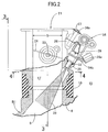
FIG. 2 is an enlarged cross-sectional view of apart 2 inFIG. 1 ; -
FIG. 3 is a cross-sectional view taken along a line 3-3 inFIG. 2 ; -
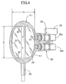
FIG. 4 is a cross-sectional view taken along a line 4-4 inFIG. 2 ; and -
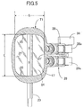
FIG. 5 is a view corresponding toFIG. 4 and showing important parts of a second embodiment of the present invention. - Embodiments of the present invention will be described below with reference to the attached drawings.
- Firstly,
FIG. 1 shows an engine E mounted on a body of an automobile, a motorcycle or the like. The engine E includes a first bank B1 and a second bank B2 which project upward from acrank supporting part 2 to together form a V shape. Thus, the engine E is formed in a V shape. Thecrank supporting part 2 supports acrank shaft 1. Each of the banks B1 and B2 includes acylinder block 3 connected to thecrank supporting part 2, and acylinder head 4 connected to the upper end of thecylinder block 3. Thecylinder block 3 includes a cylinder bore 6 in which apiston 5 reciprocates. Thecylinder head 4 includes: a combustion chamber 7 communicating with the cylinder bore 6; anintake port 8 and anexhaust port 9 which are opened to this combustion chamber 7. - As shown in
FIG. 3 , theintake port 8 includesbranched paths intake port 8 is branched from a longitudinal middle portion thereof and thebranched paths crank shaft 1 extends.Paired intake valves branched paths cylinder head 4. Theexhaust port 9 has a branched structure similar to that of theintake port 8.Paired exhaust valves 11 and 11 (only one of which is shown inFIG. 1 ) for opening and closing theexhaust port 9 are installed in thecylinder head 4 as well. - Returning to
FIG. 1 , the upstream ends of theintake ports valley 15 between the two banks B1 and B2. First and second throttle bodies T1 and T2 whoseintake passages intake ports shaped insulators valley 15. - Basically, the first and second throttle bodies T1 and T2 have the same structure. Therefore, taking the first throttle body T1 as a representative of these, descriptions will be provided referring to
FIGS. 2 to 4 . Hereinafter, the first throttle body T1 is simply referred to as a "throttle body T1." - As clearly shown in
FIG. 4 , theintake passage 17 of the throttle body T1 which communicates with theintake port 8 has a transverse cross-section formed of an oblong circle. The oblong circle has a long diameter L extending in a direction in which the paired branchedpaths intake port 8 are arranged, and a short diameter S extending orthogonal to the long diameter L. - Basically, the oblong circle shown in the drawings is formed of a combination of paired
short arcs short arcs short arcs short arcs 20 and the corresponding one of the long arcs 22 cross. - As shown in
FIGS. 2 to 4 , avalve shaft 23 is rotatably supported by the throttle body T1. Thevalve shaft 23 penetrates a longitudinal middle portion of the throttle body T1 along the long diameter L. A butterfly-type throttle valve 24 which opens and closes theintake passage 17 according to rotation of thevalve shaft 23 is fixedly attached to thevalve shaft 23. Thisthrottle valve 24 has an oblong-circle contour which matches the transverse cross-section of theintake passage 17 so as to come into close contact with the inner peripheral surface of theintake passage 17 when thethrottle valve 24 is at the closing position. - Paired
attachment bosses valley 15. The pairedattachment bosses paths fuel injection valves respective attachment bosses seal members 32 being interposed in between, respectively. Afuel joint 34 for enabling fuel to be supplied to thesefuel injection valves fuel injection valves fuel joint 34 includes a supportingarm 34a. By fixedly attaching this supportingarm 34a toattachment bosses 26 by use ofbolts 27, respectively, thefuel joint 34 is fixed to the throttle body T1, and concurrently holds the pairedfuel injection valves attachment bosses 26 are formed in the side surface of the throttle body T1. Eachfuel injection valve 28 includes apower supply coupler 28a which projects in a lateral direction. Positioningforks 34b are formed in thefuel joint 34. Eachpositioning fork 34b pinches the root of thecorresponding coupler 28a to prevent the correspondingfuel injection valve 28 from rotating. Thus, the pairedfuel injection valves fuel injection valves paths - Returning to
FIG. 1 , the first and second throttle bodies T1 and T2 mounted on the first and second banks B1 and B2 over thevalley 15 between the first andsecond banks B 1 and B2 are arranged in a way that the short diameters S of theintake passages 17 are directed in a direction in which the first and second banks B1 and B2 are arranged, respectively. In addition, afuel distributing block 36 to which the fuel is supplied from a fuel pump (not illustrated) through a fuel supplying pipe 37 is connected to the fuel joints 34 and 34 of the first and second throttle bodies T1 and T2, respectively. - Next, an operation of this embodiment will be described.
- The transverse cross-section of the
intake passage 17 of each of the first and secondthrottle bodies T 1 and T2 is formed of an oblong circle having a long diameter L extending in the direction in which the branchedpaths intake port 8 are arranged, and a short diameter S extending orthogonal to the long diameter L. This secures a large flow passage area for theintake passage 17. - In addition, any one of the sidewalls extending along the long diameter L of each of the throttle bodies T1 and T2 can have an attachment space wider than the sidewall of a throttle body which has a perfect circle cross-sectional shape and the same flow passage area. The paired
fuel injection valves fuel injection valves fuel injection valves branched paths fuel injection valves branched paths intake port 8 as little as possible, thereby leading to contributions to reduction in fuel consumption and exhaust emission. - Furthermore, it is possible to finely control a total amount of injected fuel from small flow amount to large flow amount, by operating only one
fuel injection valve 28 or by operating the twofuel injection valves intake passage 17. These factors enable the throttle body to be applied to a large displacement engine. - The contour of each of the
intake passage 17 and thethrottle valve 24 which extends along the short diameter S is formed by theshort arcs 20. Therefore, when thethrottle valve 24 is opened from its closed position even slightly, a space is formed between the end surfaces of thethrottle valve 24 extending along a direction of the short diameter S and inner surfaces of theintake passage 17, which oppose to the end surfaces. This prevents friction between the end surfaces of thethrottle valve 24 and the inner surfaces of theintake passage 17, and accordingly allows smooth opening and closing of thethrottle valve 24. - In addition, the first and second throttle bodies T1 and T2 are arranged over the
valley 15 between the first and second banks B1 and B2 of the V-type engine E in a way that the short diameters S of theirrespective intake passages 17 are directed in the direction in which the first and second banks B1 and B2 are arranged. Accordingly, the first and second throttle bodies T1 and T2 are arranged in a flat form in the direction as the two banks B1 and B2 are arranged. Accordingly, the first and second throttle bodies T1 and T2 can be easily arranged over thenarrow valley 15 without interfering with each other. - Next, a second embodiment of the present invention shown in
FIG. 5 will be described. - The engine arrangement according to the second embodiment is the same as the engine arrangement according to the above-described embodiment except for the following point. In the second embodiment, the transverse cross-section having an oblong circle of an
intake passage 17 of each of first and second throttle bodies T1 and T2 is formed of a combination of paired opposedshort arcs 20, extending along a direction of a short diameter S, and paired opposed straight lines 21' and 21' which are longer than theshort arcs FIG. 5 , parts corresponding to those of the previous embodiment will be denoted by the same reference numerals. Thereby, overlapped descriptions will be omitted. The second embodiment is capable of bringing about the same operation effect as the previous embodiment has. - The present invention is not limited to the above-mentioned embodiments and may be modified in a variety of ways as long as the modifications do not depart from the gist of the present invention as described in the claims. For instance, the paired
fuel injection valves paths - In a throttle body (T1) having fuel injection valves, an intake passage (17) is formed to have a transverse cross-section thereof in an oblong circle having a long diameter (L) extending in a direction in which paired branched paths (8a, 8a), which are formed in downstream portions of an intake port (8) of an engine (E), are arranged, and a short diameter (S) extending orthogonal to the long diameter (L); and paired fuel injection valves (28, 28) are attached to a sidewall, extending along the long diameter (L), of the throttle body (T1, T2) so as to be arranged along the long diameter (L), and to be allowed to inject fuel toward the paired branched paths (8a, 8a), respectively. Accordingly it is possible to secure a wide attachment space in the sidewall of the throttle body, to easily attach the paired parallel fuel injection valves thereto, and cause the fuel injection valves to inject fuel in adequate directions to the respective paired intake passages.
Claims (2)
- Engine arrangement comprising
a V-type engine (E) with a first bank (B1) and a second bank (B2) arranged in a V-shape,
each bank (B1, B2) comprising a combustion chamber (7) and an intake port (8) having a downstream side formed into a pair of branched paths (8a, 8a), the pair of branched paths (8a, 8a) opening towards the combustion chamber (7);
the engine arrangement furthermore comprising a first and a second throttle body arrangement associated to the first bank (B1) and to the second bank (B2) respectively,
each throttle body arrangement comprising:a throttle body (T1, T2) having an intake passage (17) communicating with an upstream end of the intake port (8) of the associated bank (B1, B2);
the intake passage (17) having a transverse cross-section in the form of an oblong circle having a long diameter (L) and a short diameter (S) extending orthogonal to the long diameter (L);
wherein the throttle body (T1,T2) is attached to the engine (E) so that the long diameter (L) extends in a direction in which the pair of branched paths (8a, 8a) of the intake port (8) of the associated bank (B1, B2) are arranged;a throttle valve (24) pivotally supported by the throttle body (T1, T2), the throttle valve (24) being adapted to open and close the intake passage (17);
the throttle valve (24) having the same contour as the oblong circle and being attached to a valve shaft (23) penetrating the throttle body (T1, T2) along the long diameter (L);a fuel injection valve arrangement (28, 28) being adapted to inject fuel towards the pair of branched paths (8a, 8a) of the intake port (8) of the associated bank (B1, B2) from a downstream side of the throttle valve (24),characterized in that the fuel injection valve arrangement (28, 28) is formed by a pair of fuel injection valves (28, 28) being fitted into respective paired attachment bosses (25, 25) each attachment boss (25) being integrally formed in a sidewall of the throttle body (T1, T2) that extends along a direction of the long diameter (L) and the pair of fuel injection valves (28, 28) being arranged in the direction of the long diameter (L),
wherein the throttle bodies (T1, T2) of the first and second throttle body arrangements are respectively attached to sidewalls of the first and second banks (B1, B2), the sidewalls facing a valley (15) between the two banks (B1, B2),
wherein the throttle bodies (B1, B2) are arranged so that the short diameters (S) of the cross-sections of the intake passages (17) are contained in a plane perpendicular to a crank shaft (1) of the engine (E), said plane extending between the first bank (B1) and the second bank (B2);
and wherein the sidewalls of the throttle bodies (T1, T2) in which the paired attachment bosses (25, 25) are integrally formed are those sidewalls of the throttle bodies (T1, T2) extending in the direction of the long diameter (L) that are closer to the middle of the valley (15). - Engine arrangement according to claim 1,
wherein the oblong circle is formed by combining paired opposed short arcs (20, 20) with paired opposed long arcs (21, 21) or paired opposed straight lines (21', 21'), the paired short arcs (20, 20) extending in a direction of the short diameter (S), the paired long arcs (21, 21) or straight lines (21', 21') being longer than the short arcs (20, 20) and extending in a direction of the long diameter (L).
Applications Claiming Priority (1)
| Application Number | Priority Date | Filing Date | Title |
|---|---|---|---|
| JP2008254841A JP2010084633A (en) | 2008-09-30 | 2008-09-30 | Throttle body having fuel injection valve |
Publications (2)
| Publication Number | Publication Date |
|---|---|
| EP2169211A1 EP2169211A1 (en) | 2010-03-31 |
| EP2169211B1 true EP2169211B1 (en) | 2016-02-10 |
Family
ID=41413835
Family Applications (1)
| Application Number | Title | Priority Date | Filing Date |
|---|---|---|---|
| EP09171587.0A Not-in-force EP2169211B1 (en) | 2008-09-30 | 2009-09-29 | Throttle body having fuel injection valve |
Country Status (2)
| Country | Link |
|---|---|
| EP (1) | EP2169211B1 (en) |
| JP (1) | JP2010084633A (en) |
Families Citing this family (6)
| Publication number | Priority date | Publication date | Assignee | Title |
|---|---|---|---|---|
| JP5802592B2 (en) * | 2012-03-29 | 2015-10-28 | 株式会社クボタ | Spark ignition engine |
| JP5893989B2 (en) * | 2012-03-29 | 2016-03-23 | 株式会社クボタ | Spark ignition engine |
| JP6395259B2 (en) * | 2014-10-14 | 2018-09-26 | ダイハツ工業株式会社 | Injector unit for internal combustion engine |
| CN105443290A (en) * | 2015-12-30 | 2016-03-30 | 无锡开普机械有限公司 | Oil sprayer assembly used for electronic injection digital generator set |
| JP7241235B2 (en) * | 2020-03-11 | 2023-03-16 | 本田技研工業株式会社 | Intake device for internal combustion engine for straddle-type vehicle |
| CN216811991U (en) * | 2022-01-14 | 2022-06-24 | 上海峰飞航空科技有限公司 | Engine and aircraft and air throttle thereof |
Family Cites Families (9)
| Publication number | Priority date | Publication date | Assignee | Title |
|---|---|---|---|---|
| JPS61261465A (en) | 1985-05-16 | 1986-11-19 | Natl Res Inst For Metals | Manufacture of compound superconductor |
| JPH0415937Y2 (en) * | 1985-10-14 | 1992-04-09 | ||
| JPS62206268A (en) * | 1986-03-05 | 1987-09-10 | Hitachi Ltd | Fuel injection device for internal combustion engine |
| JPH04128567A (en) * | 1990-09-20 | 1992-04-30 | Mazda Motor Corp | Intake device for engine |
| DE69217092T2 (en) * | 1991-02-22 | 1997-05-15 | Yamaha Motor Co Ltd | Intake system for an internal combustion engine with several valves |
| JP2591384B2 (en) * | 1991-10-07 | 1997-03-19 | 三菱自動車工業株式会社 | Engine intake system structure |
| JP3107489B2 (en) * | 1993-11-08 | 2000-11-06 | 株式会社日立製作所 | Air-fuel mixture forming device for internal combustion engine |
| JPH0914104A (en) * | 1995-06-26 | 1997-01-14 | Yamaha Motor Co Ltd | Fuel supply device for internal combustion engine |
| JP3724184B2 (en) | 1998-04-15 | 2005-12-07 | スズキ株式会社 | Fuel injection device |
-
2008
- 2008-09-30 JP JP2008254841A patent/JP2010084633A/en active Pending
-
2009
- 2009-09-29 EP EP09171587.0A patent/EP2169211B1/en not_active Not-in-force
Also Published As
| Publication number | Publication date |
|---|---|
| EP2169211A1 (en) | 2010-03-31 |
| JP2010084633A (en) | 2010-04-15 |
Similar Documents
| Publication | Publication Date | Title |
|---|---|---|
| US7707989B2 (en) | Intake port structure for engine | |
| JP4615535B2 (en) | Fuel injection control device | |
| JP4254865B2 (en) | Piston for internal combustion engine and internal combustion engine to which the piston is applied | |
| EP2169211A1 (en) | Throttle body having fuel injection valve | |
| WO2013146703A1 (en) | Air intake device for internal combustion engine | |
| US6526933B2 (en) | Multi-cylinder internal combustion engine | |
| JP2010281333A (en) | Fuel injection control device | |
| US7273032B2 (en) | Engine induction system | |
| US10968861B2 (en) | Cylinder head | |
| JP3433851B2 (en) | Engine intake control device | |
| JP2018048599A (en) | Rotary throttle device of internal combustion engine | |
| JP2005180309A (en) | Intake device for internal combustion engine | |
| JP7600426B2 (en) | Intake system for internal combustion engine | |
| EP1749997A2 (en) | Fuel injection type internal combustion engine | |
| US7137380B1 (en) | Internal combustion engine with ignition plug and vehicle provided with the same | |
| JPS6282222A (en) | Combustion chamber structure in engine | |
| JP3372378B2 (en) | Structure of spark ignition type internal combustion engine equipped with fuel injection valve | |
| US7270109B2 (en) | Internal combustion engine | |
| JP3687149B2 (en) | Direct injection diesel engine | |
| JPH10103196A (en) | Multi intake valve type engine | |
| JP2009228654A (en) | Intake device of multicylinder engine | |
| KR960034684A (en) | Direct injection diesel engine | |
| JP3885320B2 (en) | Engine intake port structure | |
| JP2971205B2 (en) | Intake control device for multi-valve engine | |
| JPH109050A (en) | Direct in-cylinder injection spark ignition engine |
Legal Events
| Date | Code | Title | Description |
|---|---|---|---|
| PUAI | Public reference made under article 153(3) epc to a published international application that has entered the european phase |
Free format text: ORIGINAL CODE: 0009012 |
|
| 17P | Request for examination filed |
Effective date: 20090929 |
|
| AK | Designated contracting states |
Kind code of ref document: A1 Designated state(s): AT BE BG CH CY CZ DE DK EE ES FI FR GB GR HR HU IE IS IT LI LT LU LV MC MK MT NL NO PL PT RO SE SI SK SM TR |
|
| 17Q | First examination report despatched |
Effective date: 20101102 |
|
| GRAP | Despatch of communication of intention to grant a patent |
Free format text: ORIGINAL CODE: EPIDOSNIGR1 |
|
| INTG | Intention to grant announced |
Effective date: 20150813 |
|
| GRAS | Grant fee paid |
Free format text: ORIGINAL CODE: EPIDOSNIGR3 |
|
| GRAA | (expected) grant |
Free format text: ORIGINAL CODE: 0009210 |
|
| AK | Designated contracting states |
Kind code of ref document: B1 Designated state(s): AT BE BG CH CY CZ DE DK EE ES FI FR GB GR HR HU IE IS IT LI LT LU LV MC MK MT NL NO PL PT RO SE SI SK SM TR |
|
| REG | Reference to a national code |
Ref country code: GB Ref legal event code: FG4D |
|
| REG | Reference to a national code |
Ref country code: AT Ref legal event code: REF Ref document number: 774781 Country of ref document: AT Kind code of ref document: T Effective date: 20160215 Ref country code: CH Ref legal event code: EP |
|
| REG | Reference to a national code |
Ref country code: IE Ref legal event code: FG4D |
|
| REG | Reference to a national code |
Ref country code: DE Ref legal event code: R096 Ref document number: 602009036157 Country of ref document: DE |
|
| REG | Reference to a national code |
Ref country code: LT Ref legal event code: MG4D |
|
| REG | Reference to a national code |
Ref country code: NL Ref legal event code: MP Effective date: 20160210 |
|
| REG | Reference to a national code |
Ref country code: AT Ref legal event code: MK05 Ref document number: 774781 Country of ref document: AT Kind code of ref document: T Effective date: 20160210 |
|
| PG25 | Lapsed in a contracting state [announced via postgrant information from national office to epo] |
Ref country code: NO Free format text: LAPSE BECAUSE OF FAILURE TO SUBMIT A TRANSLATION OF THE DESCRIPTION OR TO PAY THE FEE WITHIN THE PRESCRIBED TIME-LIMIT Effective date: 20160510 Ref country code: FI Free format text: LAPSE BECAUSE OF FAILURE TO SUBMIT A TRANSLATION OF THE DESCRIPTION OR TO PAY THE FEE WITHIN THE PRESCRIBED TIME-LIMIT Effective date: 20160210 Ref country code: HR Free format text: LAPSE BECAUSE OF FAILURE TO SUBMIT A TRANSLATION OF THE DESCRIPTION OR TO PAY THE FEE WITHIN THE PRESCRIBED TIME-LIMIT Effective date: 20160210 Ref country code: GR Free format text: LAPSE BECAUSE OF FAILURE TO SUBMIT A TRANSLATION OF THE DESCRIPTION OR TO PAY THE FEE WITHIN THE PRESCRIBED TIME-LIMIT Effective date: 20160511 Ref country code: ES Free format text: LAPSE BECAUSE OF FAILURE TO SUBMIT A TRANSLATION OF THE DESCRIPTION OR TO PAY THE FEE WITHIN THE PRESCRIBED TIME-LIMIT Effective date: 20160210 Ref country code: IT Free format text: LAPSE BECAUSE OF FAILURE TO SUBMIT A TRANSLATION OF THE DESCRIPTION OR TO PAY THE FEE WITHIN THE PRESCRIBED TIME-LIMIT Effective date: 20160210 |
|
| PG25 | Lapsed in a contracting state [announced via postgrant information from national office to epo] |
Ref country code: AT Free format text: LAPSE BECAUSE OF FAILURE TO SUBMIT A TRANSLATION OF THE DESCRIPTION OR TO PAY THE FEE WITHIN THE PRESCRIBED TIME-LIMIT Effective date: 20160210 Ref country code: PL Free format text: LAPSE BECAUSE OF FAILURE TO SUBMIT A TRANSLATION OF THE DESCRIPTION OR TO PAY THE FEE WITHIN THE PRESCRIBED TIME-LIMIT Effective date: 20160210 Ref country code: LV Free format text: LAPSE BECAUSE OF FAILURE TO SUBMIT A TRANSLATION OF THE DESCRIPTION OR TO PAY THE FEE WITHIN THE PRESCRIBED TIME-LIMIT Effective date: 20160210 Ref country code: NL Free format text: LAPSE BECAUSE OF FAILURE TO SUBMIT A TRANSLATION OF THE DESCRIPTION OR TO PAY THE FEE WITHIN THE PRESCRIBED TIME-LIMIT Effective date: 20160210 Ref country code: SE Free format text: LAPSE BECAUSE OF FAILURE TO SUBMIT A TRANSLATION OF THE DESCRIPTION OR TO PAY THE FEE WITHIN THE PRESCRIBED TIME-LIMIT Effective date: 20160210 Ref country code: IS Free format text: LAPSE BECAUSE OF FAILURE TO SUBMIT A TRANSLATION OF THE DESCRIPTION OR TO PAY THE FEE WITHIN THE PRESCRIBED TIME-LIMIT Effective date: 20160610 Ref country code: LT Free format text: LAPSE BECAUSE OF FAILURE TO SUBMIT A TRANSLATION OF THE DESCRIPTION OR TO PAY THE FEE WITHIN THE PRESCRIBED TIME-LIMIT Effective date: 20160210 Ref country code: PT Free format text: LAPSE BECAUSE OF FAILURE TO SUBMIT A TRANSLATION OF THE DESCRIPTION OR TO PAY THE FEE WITHIN THE PRESCRIBED TIME-LIMIT Effective date: 20160613 |
|
| PG25 | Lapsed in a contracting state [announced via postgrant information from national office to epo] |
Ref country code: DK Free format text: LAPSE BECAUSE OF FAILURE TO SUBMIT A TRANSLATION OF THE DESCRIPTION OR TO PAY THE FEE WITHIN THE PRESCRIBED TIME-LIMIT Effective date: 20160210 Ref country code: EE Free format text: LAPSE BECAUSE OF FAILURE TO SUBMIT A TRANSLATION OF THE DESCRIPTION OR TO PAY THE FEE WITHIN THE PRESCRIBED TIME-LIMIT Effective date: 20160210 |
|
| PGFP | Annual fee paid to national office [announced via postgrant information from national office to epo] |
Ref country code: DE Payment date: 20160920 Year of fee payment: 8 |
|
| REG | Reference to a national code |
Ref country code: DE Ref legal event code: R097 Ref document number: 602009036157 Country of ref document: DE |
|
| PG25 | Lapsed in a contracting state [announced via postgrant information from national office to epo] |
Ref country code: SM Free format text: LAPSE BECAUSE OF FAILURE TO SUBMIT A TRANSLATION OF THE DESCRIPTION OR TO PAY THE FEE WITHIN THE PRESCRIBED TIME-LIMIT Effective date: 20160210 Ref country code: CZ Free format text: LAPSE BECAUSE OF FAILURE TO SUBMIT A TRANSLATION OF THE DESCRIPTION OR TO PAY THE FEE WITHIN THE PRESCRIBED TIME-LIMIT Effective date: 20160210 Ref country code: SK Free format text: LAPSE BECAUSE OF FAILURE TO SUBMIT A TRANSLATION OF THE DESCRIPTION OR TO PAY THE FEE WITHIN THE PRESCRIBED TIME-LIMIT Effective date: 20160210 Ref country code: RO Free format text: LAPSE BECAUSE OF FAILURE TO SUBMIT A TRANSLATION OF THE DESCRIPTION OR TO PAY THE FEE WITHIN THE PRESCRIBED TIME-LIMIT Effective date: 20160210 |
|
| PLBE | No opposition filed within time limit |
Free format text: ORIGINAL CODE: 0009261 |
|
| STAA | Information on the status of an ep patent application or granted ep patent |
Free format text: STATUS: NO OPPOSITION FILED WITHIN TIME LIMIT |
|
| PG25 | Lapsed in a contracting state [announced via postgrant information from national office to epo] |
Ref country code: BE Free format text: LAPSE BECAUSE OF FAILURE TO SUBMIT A TRANSLATION OF THE DESCRIPTION OR TO PAY THE FEE WITHIN THE PRESCRIBED TIME-LIMIT Effective date: 20160210 |
|
| 26N | No opposition filed |
Effective date: 20161111 |
|
| PG25 | Lapsed in a contracting state [announced via postgrant information from national office to epo] |
Ref country code: SI Free format text: LAPSE BECAUSE OF FAILURE TO SUBMIT A TRANSLATION OF THE DESCRIPTION OR TO PAY THE FEE WITHIN THE PRESCRIBED TIME-LIMIT Effective date: 20160210 Ref country code: BG Free format text: LAPSE BECAUSE OF FAILURE TO SUBMIT A TRANSLATION OF THE DESCRIPTION OR TO PAY THE FEE WITHIN THE PRESCRIBED TIME-LIMIT Effective date: 20160510 |
|
| PG25 | Lapsed in a contracting state [announced via postgrant information from national office to epo] |
Ref country code: MC Free format text: LAPSE BECAUSE OF FAILURE TO SUBMIT A TRANSLATION OF THE DESCRIPTION OR TO PAY THE FEE WITHIN THE PRESCRIBED TIME-LIMIT Effective date: 20160210 |
|
| REG | Reference to a national code |
Ref country code: CH Ref legal event code: PL |
|
| GBPC | Gb: european patent ceased through non-payment of renewal fee |
Effective date: 20160929 |
|
| REG | Reference to a national code |
Ref country code: IE Ref legal event code: MM4A |
|
| REG | Reference to a national code |
Ref country code: FR Ref legal event code: ST Effective date: 20170531 |
|
| PG25 | Lapsed in a contracting state [announced via postgrant information from national office to epo] |
Ref country code: GB Free format text: LAPSE BECAUSE OF NON-PAYMENT OF DUE FEES Effective date: 20160929 Ref country code: LI Free format text: LAPSE BECAUSE OF NON-PAYMENT OF DUE FEES Effective date: 20160930 Ref country code: CH Free format text: LAPSE BECAUSE OF NON-PAYMENT OF DUE FEES Effective date: 20160930 Ref country code: FR Free format text: LAPSE BECAUSE OF NON-PAYMENT OF DUE FEES Effective date: 20160930 Ref country code: IE Free format text: LAPSE BECAUSE OF NON-PAYMENT OF DUE FEES Effective date: 20160929 |
|
| PG25 | Lapsed in a contracting state [announced via postgrant information from national office to epo] |
Ref country code: LU Free format text: LAPSE BECAUSE OF NON-PAYMENT OF DUE FEES Effective date: 20160929 |
|
| REG | Reference to a national code |
Ref country code: DE Ref legal event code: R119 Ref document number: 602009036157 Country of ref document: DE |
|
| PG25 | Lapsed in a contracting state [announced via postgrant information from national office to epo] |
Ref country code: HU Free format text: LAPSE BECAUSE OF FAILURE TO SUBMIT A TRANSLATION OF THE DESCRIPTION OR TO PAY THE FEE WITHIN THE PRESCRIBED TIME-LIMIT; INVALID AB INITIO Effective date: 20090929 Ref country code: CY Free format text: LAPSE BECAUSE OF FAILURE TO SUBMIT A TRANSLATION OF THE DESCRIPTION OR TO PAY THE FEE WITHIN THE PRESCRIBED TIME-LIMIT Effective date: 20160210 |
|
| PG25 | Lapsed in a contracting state [announced via postgrant information from national office to epo] |
Ref country code: MK Free format text: LAPSE BECAUSE OF FAILURE TO SUBMIT A TRANSLATION OF THE DESCRIPTION OR TO PAY THE FEE WITHIN THE PRESCRIBED TIME-LIMIT Effective date: 20160210 Ref country code: TR Free format text: LAPSE BECAUSE OF FAILURE TO SUBMIT A TRANSLATION OF THE DESCRIPTION OR TO PAY THE FEE WITHIN THE PRESCRIBED TIME-LIMIT Effective date: 20160210 Ref country code: MT Free format text: LAPSE BECAUSE OF NON-PAYMENT OF DUE FEES Effective date: 20160930 |
|
| PG25 | Lapsed in a contracting state [announced via postgrant information from national office to epo] |
Ref country code: DE Free format text: LAPSE BECAUSE OF NON-PAYMENT OF DUE FEES Effective date: 20180404 |