EP2168788A1 - Method and device for carrying out wheel stand regulation for commercial vehicles - Google Patents
Method and device for carrying out wheel stand regulation for commercial vehicles Download PDFInfo
- Publication number
- EP2168788A1 EP2168788A1 EP09008299A EP09008299A EP2168788A1 EP 2168788 A1 EP2168788 A1 EP 2168788A1 EP 09008299 A EP09008299 A EP 09008299A EP 09008299 A EP09008299 A EP 09008299A EP 2168788 A1 EP2168788 A1 EP 2168788A1
- Authority
- EP
- European Patent Office
- Prior art keywords
- compressed air
- adjusting means
- axles
- pressure
- valve
- Prior art date
- Legal status (The legal status is an assumption and is not a legal conclusion. Google has not performed a legal analysis and makes no representation as to the accuracy of the status listed.)
- Withdrawn
Links
- 238000000034 method Methods 0.000 title claims abstract description 16
- 230000033228 biological regulation Effects 0.000 title description 2
- 238000007599 discharging Methods 0.000 claims description 3
- 210000004712 air sac Anatomy 0.000 description 8
- 238000013022 venting Methods 0.000 description 6
- 238000013461 design Methods 0.000 description 5
- 239000000725 suspension Substances 0.000 description 4
- 230000008859 change Effects 0.000 description 3
- 238000010276 construction Methods 0.000 description 2
- 230000008878 coupling Effects 0.000 description 2
- 238000010168 coupling process Methods 0.000 description 2
- 238000005859 coupling reaction Methods 0.000 description 2
- 230000005283 ground state Effects 0.000 description 2
- 238000012423 maintenance Methods 0.000 description 2
- 230000008569 process Effects 0.000 description 2
- 238000009423 ventilation Methods 0.000 description 2
- 230000000740 bleeding effect Effects 0.000 description 1
- 230000007423 decrease Effects 0.000 description 1
- 230000001419 dependent effect Effects 0.000 description 1
- 238000011161 development Methods 0.000 description 1
- 238000006073 displacement reaction Methods 0.000 description 1
- 230000000694 effects Effects 0.000 description 1
- 230000014759 maintenance of location Effects 0.000 description 1
- 238000012986 modification Methods 0.000 description 1
- 230000004048 modification Effects 0.000 description 1
- 230000003287 optical effect Effects 0.000 description 1
- 238000009987 spinning Methods 0.000 description 1
- 230000037303 wrinkles Effects 0.000 description 1
Images


Classifications
-
- B—PERFORMING OPERATIONS; TRANSPORTING
- B60—VEHICLES IN GENERAL
- B60G—VEHICLE SUSPENSION ARRANGEMENTS
- B60G17/00—Resilient suspensions having means for adjusting the spring or vibration-damper characteristics, for regulating the distance between a supporting surface and a sprung part of vehicle or for locking suspension during use to meet varying vehicular or surface conditions, e.g. due to speed or load
- B60G17/02—Spring characteristics, e.g. mechanical springs and mechanical adjusting means
- B60G17/04—Spring characteristics, e.g. mechanical springs and mechanical adjusting means fluid spring characteristics
- B60G17/052—Pneumatic spring characteristics
- B60G17/0523—Regulating distributors or valves for pneumatic springs
-
- B—PERFORMING OPERATIONS; TRANSPORTING
- B60—VEHICLES IN GENERAL
- B60G—VEHICLE SUSPENSION ARRANGEMENTS
- B60G2300/00—Indexing codes relating to the type of vehicle
- B60G2300/04—Trailers
-
- B—PERFORMING OPERATIONS; TRANSPORTING
- B60—VEHICLES IN GENERAL
- B60G—VEHICLE SUSPENSION ARRANGEMENTS
- B60G2400/00—Indexing codes relating to detected, measured or calculated conditions or factors
- B60G2400/50—Pressure
- B60G2400/51—Pressure in suspension unit
- B60G2400/512—Pressure in suspension unit in spring
- B60G2400/5122—Fluid spring
- B60G2400/51222—Pneumatic
-
- B—PERFORMING OPERATIONS; TRANSPORTING
- B60—VEHICLES IN GENERAL
- B60G—VEHICLE SUSPENSION ARRANGEMENTS
- B60G2800/00—Indexing codes relating to the type of movement or to the condition of the vehicle and to the end result to be achieved by the control action
- B60G2800/21—Traction, slip, skid or slide control
- B60G2800/214—Traction, slip, skid or slide control by varying the load distribution
Definitions
- the present invention relates to a device for carrying out a wheelbase control for commercial vehicles comprising one or more axles with wheels, one or more acted upon by compressed air adjusting means for adjusting at least one of the axes relative to a structure and a pressure sensor for measuring the pressure of the compressed air in the adjusting means and for generating corresponding signals, as well as a corresponding method.
- the device relates to a commercial vehicle which has such a device and with which the method according to the invention can be carried out.
- Such devices, devices and methods for wheelbase control are known from the prior art.
- a construction will be understood as meaning all units of a utility vehicle which are carried by a chassis arrangement of the utility vehicle. This can be a body, a cargo bed or a cargo hold.
- Under wheelbase regulations are understood here all functions that are related to the raising or lowering of one or more axles of a commercial vehicle.
- raising or lowering one or more axles of the wheelbase of the commercial vehicle is changed and changed the load of the other axes targeted.
- a traction help can be realized in that the wheels of the driven axles are more heavily loaded and thereby the adhesion between the wheels and the roadway is increased. Consequently, a spinning of the driven wheels is made more difficult, so that, in particular on snow-covered or icy roadways, the start-up procedure is made easier or even made possible in the first place.
- the maneuvering of the utility vehicle can also be facilitated by lifting one or more axles. When maneuvering, the strongest steering deflections are present.
- Known devices for wheelbase control include one or more acted upon by compressed air adjustment means which are arranged between the axles and a structure of the utility vehicle.
- compressed air adjustment means By applying the adjusting means with compressed air, a pressure is generated in the adjusting means, which correlates with the amount of the incoming compressed air.
- the amount of compressed air with which the adjusting means are acted is Controlled in the art, for example by means of an overflow valve without a check or a pressure relief valve with make-up, the control of these valves can be done manually by the driver or electronically.
- these valves tend not to keep the set pressure, especially at pressure peaks. Pressure peaks occur, for example, when an axle is to be lowered at full load of the commercial vehicle.
- a method for minimum pressure retention in an air spring bellows a support axle is from the DE 10 2004 036 251 A1 known.
- the voltages within the landing gear assembly are determined using a displacement sensor, as the stresses cause a change in the distance between the axles and the structure.
- the adjusting means are controlled so that the voltages are reduced.
- the minimum pressure in the bellows is not determined directly here, but the air bellows is always so pressurized with compressed air that a minimum distance between the axis and the structure is not exceeded.
- the problem of not guaranteed pressure value of the valves used is by the in the DE 10 2004 036 251 A1 proposed solution not solved.
- the object of the present invention is therefore to provide a device and a method with which it is possible to overcome the disadvantages of the prior art and to easily ensure a minimum pressure in Verstellstoffn.
- Pulse-controlled valves for selectively supplying and removing the compressed air in the adjustment and out of the adjustment.
- Pulse-controlled valves comprise two actuators, via which the ventilation of the actuators and / or the lifting and lowering of the axles is carried out. This is one each Actuator activated. If both actuators are activated simultaneously, a stop is defined. In this way, any pressure can be adjusted and held in the adjusting means, whereby the axis can be continuously brought and held in any position.
- the minimum pressure maintenance or the attitude of a predetermined pressure value in the adjusting means can be realized in comparison to conventional devices without significant additional costs. Furthermore, it can be checked directly using the pressure sensor, whether the pressure in the adjusting means falls below a predetermined minimum value or not. It is compared to the one in the DE 10 2004 036 251 A1 proposed solution is not necessary to determine a chassis-dependent correlation between the distance of the axis of the structure and the pressure prevailing in the adjusting pressure.
- the pressure sensor may output the signals relating to the pressure in any suitable form, for example as optical signals in the form of a display device, so that the driver can see whether the pressure falls below a certain minimum value. Furthermore, it is conceivable to output the signals in electronic form.
- a spring-return valve for selectively supplying and discharging the compressed air in the adjustment and out of the adjustment and another valve for selectively shutting off the discharge of compressed air from the adjusting out.
- Spring-return valves are simple in design and cost-effective to purchase and are also characterized by a high level of ruggedness and reliability. However, they can only be switched in binary between a ventilating and a venting position.
- the valve has an actuator which brings a slider or a valve body when activated against the force of a spring in a position in which the adjusting means is vented. If the actuator is deactivated, the slide is returned to its original position and the adjusting means ventilated. Consequently, the axis can only be moved between two end positions.
- This configuration of the spring-return valves is achieved that they automatically open in case of failure of the on-board electronics and ventilate the adjustment, so that in the adjustment of the maximum pressure is applied.
- the adjusting means are also in the ground state, whereby the axle is in a fully lowered position in which it is subjected to maximum load. If the axle is now to be relieved, the spring return valve is opened. Without the additional valve, the compressed air would be complete escape from the air bellows and the axle are in the fully raised position.
- the further valve blocks the discharge of compressed air at a predeterminable pressure in the air bellows, so that in this embodiment, the axis can be driven in all the desired intermediate stages. At the same time, it is ensured that the set pressure value is maintained even under high load. Furthermore, falling below a minimum pressure value is surely prevented.
- the device is controlled by a control device, in particular an EBS modulator for receiving the signals generated by the pressure sensor and for driving the pulse-controlled valve, the spring-return valve and the further valve, which are controllable by means of the control device.
- the signals of the pressure sensor are output in electronic form.
- Control devices, in particular EBS modulators are present in every modern commercial vehicle and convert control signals into corresponding pneumatic signals, for example for controlling pneumatically operated brakes. There is no significant additional technical effort necessary to extend the EBS modulator so that it undercuts a selectable minimum pressure in the adjustment means the valve controls so that compressed air flows as long as in the adjustment until the minimum pressure is reached again.
- the configuration of the EBS modulators can either be factory-adjusted by the service or by the driver himself flexibly and without great effort to the respective vehicle type, in particular, the value of the minimum pressure which is to prevail in the adjusting means can be changed quickly. Furthermore, EBS modulators are equipped so that all collected data and configuration changes can be stored and analyzed at any time. In this way it can be determined, for example, which minimum pressure is particularly well suited to protect the wheel bearings or whether a leak in the adjusting means is present and an exchange should be made. Therefore, manual input of the minimum pressure value, which is difficult to control in conventional systems, is eliminated. The controllability of the pulse-controlled valve, the spring-return valve and the other valve by means of the EBS modulator is also no difficulty.
- the two actuators of the pulse-controlled valve can be configured as a magnet. With simultaneous energization of these magnets, any holding position can be controlled and the relevant axis can be moved and held continuously in any position.
- the pulse-controlled valve can be connected to the EBS modulator and actuated by it according to the measured pressure values in the adjusting means. This also applies analogously to the further and the spring-return valve.
- the adjusting means is designed as an air bellows.
- Air bellows are widely used in commercial vehicle construction, are inexpensive to purchase and are characterized by a high level of reliability. However, they tend to wrinkle when completely deaerated.
- the minimum pressure can be selected so that the air bellows are vented only to the extent that they do not crumple. Consequently, the life of the air bladder is further increased.
- the device is developed in that the device comprises three axes, two of which are formed as a main axis and one as a trailing axle.
- the main axis is an axis, which is always in contact with the road, is not steerable and can not be adjusted in their distance from the structure.
- Main axles also have air bellows, but they do not serve for adjustment, but for suspension.
- a trailing axle refers to an axle which can be adjusted in its distance from the superstructure by means of the adjusting means, for example pneumatic bellows.
- the trailing axle is loaded only when a predefinable critical axle load of the main axle or main axles is exceeded, and in turn is relieved as soon as the axle load of the main axle falls below a predefinable value.
- This critical axle load is determined by the pressure value in the air bellows of the trailing axle.
- drag axles are in contact with the road surface due to their own weight, since they have no lift bellows, as is the case with lift axles.
- Lift axles can be lifted with the lifting bellows, which act via a lever system opposite to the bellows, far enough that they no longer have any contact with the road. Lift axles are not affected by the problem underlying the present invention. Since they are raised so far that they are decoupled from the road, it comes in contrast to trailing axles not damage to camps or on the chassis assembly, for example, when driving over potholes.
- the EBS modulator can be configured so that the trailing axle can only be operated below a certain speed, for example up to 30 km / h. Thus, a sudden load change while driving by accidental operation of the trailing axle by the driver can be avoided. Furthermore, the EBS modulator can also be configured so that the trailing axle is automatically lowered when the certain speed is exceeded, unless it is already in the lowered state or further lowered to keep the load on the main axes low. This makes sense if the commercial vehicle is heavily loaded.
- the device is advantageously further developed in that the device comprises five axles, two of which are steerable and three are non-steerable, of the three non-steerable axles two being designed as main axle and one as trailing axle.
- This development is a characteristic embodiment of a trailer of so-called “overlong truck,” also known as “EuroCombi” or “Gigaliner”, with which many and large loads can be transported.
- the wheel bearings and the road are not too heavily loaded, preferably five axes must be provided.
- high stresses occur between the axles, especially between the two steerable axles, but also between the three adjacent non-steerable axles.
- the invention is further developed in that the device comprises three axes, one of which is steerable and at least one driven, wherein an axis is not steerable, not driven and designed as a drag axis.
- This embodiment is in towing vehicles, so the invention is not limited to commercial vehicles without their own drive.
- the advantages of the device according to the invention come in towing vehicles as well as in trailer vehicles.
- trailing axles are not steerable and driven, but the applicability of the present invention is not limited thereto. Rather, it is conceivable to design also driven and / or steerable axles and lifting axles according to the invention.
- Another aspect of the present invention relates to a commercial vehicle having a device for carrying out a wheelbase control according to one of claims 1 to 9.
- the advantages described for the device according to the invention fully apply to a commercial vehicle which uses the device according to the invention.
- the commercial vehicle may for example be a trailer or a towing vehicle.
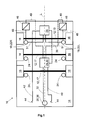
- FIG. 1 a first embodiment of the device 10 according to the invention is shown.
- the device 10 comprises three axles 12, of which two axles are designed as main axles 17 and the third axle as towing axle 13.
- the applicability of the present invention is not limited to any particular number of axes.
- This embodiment is typical of a semi-trailer 14 (see. FIG. 3 ).
- Each axle 12 are each associated with two wheels 16, wherein an axle may be associated with more wheels, as is the case with twin tires.
- the trailing axle 13 is associated with an adjusting means 18, with which the axis 13 can be adjusted relative to a structure 20, not shown here (see. Figures 3 and 4 ).
- the adjusting means 18 are designed as air bellows 22, which can be acted upon with compressed air.
- the right air bellows of the trailing axle 13 is denoted by 22R for distinction, the left with 22L.
- the main axles 17 also have air bellows 24, but they do not act as adjusting means, but serve exclusively for the suspension of the semitrailer 14.
- the device 10 comprises a pulse-controlled valve 26 for selectively aerating and venting the air bladder 22.
- a pulse-controlled valve is here in the embodiment, a 3/3 way valve referred to, which can occupy the positions venting, venting and holding.
- This pulse-controlled valve 26 is controlled by a control device 28, designed as EBS modulator 30.
- the EBS modulator 30 is connected via a first electrical line 32 with a in FIG. 1 not shown towing vehicle 34 (see. FIG. 3 and 4 ) to exchange data and commands with the towing vehicle 34.
- the electrical connection between the towing vehicle 34 and the semitrailer 14 via a mechanical coupling 35 carried out as a Aufliegyak 36 over which all occurring between the towing vehicle 34 and the semitrailer 14 mechanical forces are transmitted.
- a mechanical coupling 35 carried out as a Aufliegyak 36 over which all occurring between the towing vehicle 34 and the semitrailer 14 mechanical forces are transmitted.
- the control of the pulse-controlled valve 26 is realized via a second electrical line 38.
- the compressed air is held by two in the tractor 34 located compressed air reservoirs, of which a first pneumatic line 40 in the EBS modulator 30 and a second pneumatic line 42 open into the pulse-controlled valve 26.
- the pneumatic connection between the towing vehicle 34 and the semitrailer 14 is done here via pneumatic connectors 44.
- a third pneumatic line 48 leads to the air bladder 22.
- a pressure sensor 46 is assigned to each of these , The pressure sensor 46 is connected to the air bellows 22 via a fourth pneumatic line 51 and converts the measured pressure into corresponding electrical signals, which are conducted via a third electrical line 49 to the EBS modulator 30.
- a separate pressure sensor 46 is provided for each pneumatic bellows 22.
- the pulse-controlled valve 26 is configured to separately ventilate the left and right air bladders 22L and 22R.
- only one pressure sensor 46 may be provided and the pulse-controlled valve 26 may be configured so that the left and right air bladders 22L and 22R are ventilated and vented together.
- the operation of the device 10 according to the invention is exemplified by an example, starting from a ground state in which all axes 12 are fully lowered, so all the air bladder 22 are fully vented.
- the driver of the towing vehicle 34 now wants to make a maneuvering, to which he gives the command to raise the trailing axle 13 completely.
- This command passes through the Auflieg Vietnamese 36 and the first electrical line 32 to the EBS modulator 30, which in turn controls the pulse-controlled valve 26 so that the Lucasbalge 22 of the trailing axle 13 are vented and the trailing axle 13 is raised.
- the bleeding process continues until a certain predefinable minimum pressure is reached.
- the pressure sensor 46 sends a corresponding signal to the EBS modulator 30, which in turn controls the pulse-controlled valve 26 so that the venting is terminated. If the pressure falls, for example by porosities in the air bellows 22 below the minimum pressure, the pressure sensor 46 sends a corresponding signal to the EBS modulator 30, which controls the pulse-controlled valve 26 so that the minimum pressure is reached again.
- the EBS modulator 30 it is also possible to configure the EBS modulator 30 so that the trailing axle 13 can be raised or lowered only at a certain speed to avoid load changes during the journey. It is also possible to automatically lower the towing axle 13 when the axle load of the main axles 17 exceeds a certain value.
- any desired pressure in the air bellows 22 can be steplessly controlled, with a determinable minimum pressure in the air bellows 22 not being exceeded.
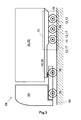
- FIG. 2 a further embodiment of the device 10 according to the invention is shown.
- the basic structure 20 of the device 10 corresponds to that of the in FIG. 1 illustrated embodiment.
- no pulse-controlled valve but a spring-return valve 50 and another valve 52 is used, wherein the spring-return valve 50 via the second electrical line 38 and the further valve 52 via a fourth electrical line 53 to the EBS modulator 30th is connected.
- the spring-return valve 50 can only be activated in binary mode by the EBS modulator 30, ie either open or closed. The control of a certain pressure between the maximum pressure predetermined by the compressed air reservoir and the atmospheric pressure in the pneumatic bellows 22 is not possible with the spring-return valve 50 alone.
- the further valve 52 is used, which, as shown, is located directly on the spring return valve 50, or as a separate unit via a pneumatic line to the spring return valve 50 is connected (not shown) ,
- the further valve is controlled by the EBS modulator 30 so that on the one hand the desired pressure in the air bellows 22 is present and on the other hand, the desired minimum pressure is not exceeded.
- FIG. 3 is a first commercial vehicle combination 54 consisting of a towing vehicle 34 and a semi-trailer 14 with a device 10 according to the invention shown, wherein the semi-trailer 14 comprises a device 10 according to the invention.
- the semitrailer 14 is coupled via the support point 36 with the towing vehicle 34 and comprises two main axes 17 and a trailing axle 13.
- FIG. 4 a second commercial vehicle combination 56 consisting of a towing vehicle 34 and a drawbar trailer 58 with a tandem drawbar 62 with a device 10 according to the invention.
- the drawbar trailer 58 is connected to the towing vehicle 34 via a mechanical coupling 35.
- both the towing vehicle 34 and the drawbar trailer 58 have the device 10 according to the invention.
- the towing vehicle 34 comprises two main axles 17, one of which is steerable. One or both main axes 17 are driven.
- the tractor 34 has a trailing axle 13.
- the drawbar trailer 58 has a total of five axles 12, two of which are combined to form the tandem drawbar 62 and thus steer the trailer.
- One of these axles 12 is designed as a trailing axle 13. Of the remaining three axles 12, two are designed as the main axis 17 and one as the trailing axle 13.
- the use of the device 10 according to the invention ensures that during the venting of the trailing axles 13, a certain minimum pressure in the bellows 22 is not exceeded.
Landscapes
- Engineering & Computer Science (AREA)
- Mechanical Engineering (AREA)
- Vehicle Body Suspensions (AREA)
Abstract
Description
Die vorliegende Erfindung betrifft eine Vorrichtung zum Durchführen einer Radstandregelung für Nutzfahrzeuge umfassend eine oder mehrere Achsen mit Rädern, ein oder mehrere mit Druckluft beaufschlagbare Verstellmittel zum Verstellen mindestens einer der Achsen relativ zu einem Aufbau und einen Drucksensor zum Messen des Drucks der Druckluft in den Verstellmitteln und zum Erzeugen von entsprechenden Signalen, sowie ein entsprechendes Verfahren. Weiterhin betrifft die Vorrichtung ein Nutzfahrzeug, welches eine derartige Vorrichtung aufweist und mit welchem das erfindungsgemäße Verfahren ausgeführt werden kann. Derartige Vorrichtungen, Vorrichtungen und Verfahren zur Radstandregelung sind aus dem Stand der Technik bekannt. Unter einem Aufbau werden im Folgenden sämtliche Einheiten eines Nutzfahrzeuges verstanden werden, die von einer Fahrwerksanordnung des Nutzfahrzeuges getragen werden. Dies kann eine Karosserie, eine Ladefläche oder ein Frachtraum sein. Unter Radstandregelungen werden hier alle Funktionen verstanden, die im Zusammenhang mit dem Heben oder Senken einer oder mehrerer Achsen eines Nutzfahrzeuges stehen. Durch das Heben oder Senken einer oder mehrerer Achsen wird der Radstand des Nutzfahrzeuges verändert und die Belastung der übrigen Achsen zielgerichtet verändert. Somit lässt sich beispielsweise eine Anfahrhilfe dadurch realisieren, dass die Räder der angetriebenen Achsen stärker belastet werden und dadurch die Haftung zwischen den Rädern und der Fahrbahn erhöht wird. Folglich wird ein Durchdrehen der angetriebenen Räder erschwert, so dass insbesondere auf schneebedeckten oder vereisten Fahrbahnen ein der Anfahrvorgang erleichtert oder überhaupt erst ermöglicht wird. Weiterhin kann das Rangieren des Nutzfahrzeuges ebenfalls durch Anheben einer oder mehrerer Achsen erleichtert werden. Beim Rangieren liegen die stärksten Lenkausschläge vor. Als Folge davon treten zwischen den Achsen hohe Spannungen auf, insbesondere, wenn zwei oder mehrere benachbarte nicht gelenkte Achsen vorhanden sind. Dadurch dass sich die Haftung zwischen den Rädern der angehobenen Achsen und der Fahrbahn verringert, reduzieren sich auch diese Spannungen. Folglich nimmt der Verschleiß der Räder und Radlager ab.The present invention relates to a device for carrying out a wheelbase control for commercial vehicles comprising one or more axles with wheels, one or more acted upon by compressed air adjusting means for adjusting at least one of the axes relative to a structure and a pressure sensor for measuring the pressure of the compressed air in the adjusting means and for generating corresponding signals, as well as a corresponding method. Furthermore, the device relates to a commercial vehicle which has such a device and with which the method according to the invention can be carried out. Such devices, devices and methods for wheelbase control are known from the prior art. In the following, a construction will be understood as meaning all units of a utility vehicle which are carried by a chassis arrangement of the utility vehicle. This can be a body, a cargo bed or a cargo hold. Under wheelbase regulations are understood here all functions that are related to the raising or lowering of one or more axles of a commercial vehicle. By raising or lowering one or more axles of the wheelbase of the commercial vehicle is changed and changed the load of the other axes targeted. Thus, for example, a traction help can be realized in that the wheels of the driven axles are more heavily loaded and thereby the adhesion between the wheels and the roadway is increased. Consequently, a spinning of the driven wheels is made more difficult, so that, in particular on snow-covered or icy roadways, the start-up procedure is made easier or even made possible in the first place. Furthermore, the maneuvering of the utility vehicle can also be facilitated by lifting one or more axles. When maneuvering, the strongest steering deflections are present. As a result, high voltages occur between the axles, especially when two or more adjacent non-steered axles are present. By reducing the adhesion between the wheels of the raised axles and the road, these stresses are also reduced. Consequently, the wear of the wheels and wheel bearings decreases.
Bekannte Vorrichtungen zur Radstandregelung umfassen ein oder mehrere mit Druckluft beaufschlagbare Verstellmittel, welche zwischen den Achsen und einem Aufbau des Nutzfahrzeuges angeordnet sind. Durch Beaufschlagen der Verstellmittel mit Druckluft wird in den Verstellmitteln ein Druck erzeugt, welcher mit der Menge der eingeströmten Druckluft korreliert. Die Menge der Druckluft, mit welcher die Verstellmittel beaufschlagt werden, wird im Stand der Technik beispielsweise mithilfe eines Überstromventils ohne Rückschlag oder eines Druckbegrenzungsventils mit Nachspeisung gesteuert, wobei die Steuerung dieser Ventile manuell durch den Fahrer oder elektronisch erfolgen kann. Diese Ventile neigen allerdings dazu, den eingestellten Druckwert insbesondere bei Druckspitzen nicht zu halten. Druckspitzen treten zum Beispiel dann auf, wenn eine Achse bei Volllast des Nutzfahrzeuges gesenkt werden soll. Wird der Druckwert nicht gehalten, führt dies dazu, dass die gewünschte Entlastung der anderen Achsen nicht mehr gewährleistet wird und die anderen Achsen stärker als gewünscht oder sogar stärker als erlaubt belastet werden. Als Folge erhöht sich der Verschleiß der Radlager an den anderen Achsen, die im Extremfall versagen können. Weiterhin tritt bei der Verwendung dieser Ventile die Situation auf, dass ein vorgesehener Mindestdruck in den Verstellmitteln unterschritten wird. Die Verstellmittel übernehmen zumindest teilweise die Federung des Nutzfahrzeuges. Ein Mindestdruck ist deshalb notwendig, damit die Verstellmittel ihre minimal notwendige Federungswirkung entfalten können. Wird der Mindestdruck unterschritten, so würden beispielsweise beim Überfahren von Schlaglöchern, Bahnschwellen oder Bodenwellen auftretende Berührungen mit den Rädern ohne Abfederung direkt in die Fahrwerksanordnung eingeleitet, die dadurch stark belastet wird. Folglich verschleißt diese schneller oder wird beschädigt.Known devices for wheelbase control include one or more acted upon by compressed air adjustment means which are arranged between the axles and a structure of the utility vehicle. By applying the adjusting means with compressed air, a pressure is generated in the adjusting means, which correlates with the amount of the incoming compressed air. The amount of compressed air with which the adjusting means are acted, is Controlled in the art, for example by means of an overflow valve without a check or a pressure relief valve with make-up, the control of these valves can be done manually by the driver or electronically. However, these valves tend not to keep the set pressure, especially at pressure peaks. Pressure peaks occur, for example, when an axle is to be lowered at full load of the commercial vehicle. If the pressure is not maintained, this will result in the desired relief of the other axles being no longer guaranteed and the other axles being loaded more than desired or even more than allowed. As a result, the wear of the wheel bearings increases on the other axles, which can fail in extreme cases. Furthermore, when using these valves, the situation occurs that an intended minimum pressure in the adjusting means is exceeded. The adjusting take at least partially the suspension of the commercial vehicle. A minimum pressure is therefore necessary so that the adjusting means can develop their minimum necessary suspension effect. If the minimum pressure is not reached, contact with the wheels, for example when driving over potholes, railway sleepers or bumps, without springing, would be introduced directly into the chassis arrangement, which would then be heavily loaded. As a result, it wears faster or gets damaged.
Ein Verfahren zur Mindestdruckhaltung in einem Luftfederbalg einer Tragachse ist aus der
Aufgabe der vorliegenden Erfindung ist es daher, eine Vorrichtung und ein Verfahren anzugeben, mit denen es möglich ist, die Nachteile aus dem Stand der Technik zu überwinden und auf einfache Weise eine Mindestdruckhaltung in Verstellmitteln zu gewährleisten.The object of the present invention is therefore to provide a device and a method with which it is possible to overcome the disadvantages of the prior art and to easily ensure a minimum pressure in Verstellmitteln.
Gelöst wird die Aufgabe durch ein impulsgesteuertes Ventil zum wahlweisen Zu- und Abführen der Druckluft in die Verstellmittel und aus den Verstellmitteln heraus. Impulsgesteuerte Ventile umfassen zwei Stellglieder, über die das Be- und Entlüften der Verstellmittel bzw. das Heben und Senken der Achsen vorgenommen wird. Hierzu wird je ein Stellglied aktiviert. Werden beide Stellglieder gleichzeitig aktiviert, wird eine Haltestelle definiert. Auf diese Weise kann jeder beliebige Druck im Verstellmittel eingestellt und gehalten werden, wodurch die Achse stufenlos in jede Stellung gebracht und gehalten werden kann.The problem is solved by a pulse-controlled valve for selectively supplying and removing the compressed air in the adjustment and out of the adjustment. Pulse-controlled valves comprise two actuators, via which the ventilation of the actuators and / or the lifting and lowering of the axles is carried out. This is one each Actuator activated. If both actuators are activated simultaneously, a stop is defined. In this way, any pressure can be adjusted and held in the adjusting means, whereby the axis can be continuously brought and held in any position.
Da Drucksensoren in vielen Nutzfahrzeugen zur Bestimmung des Drucks in den Luftbalgen vorhanden sind, sind keine weiteren mechanischen Komponenten notwendig. Mit der erfindungsgemäßen Vorrichtung kann die Mindestdruckhaltung bzw. die Haltung eines vorgegebenen Druckwertes in den Verstellmitteln im Vergleich zu herkömmlichen Vorrichtungen ohne nennenswerte Mehrkosten realisiert werden. Weiterhin kann mithilfe des Drucksensors unmittelbar überprüft werden, ob der Druck im Verstellmittel einen vorgegebenen Minimalwert unterschreitet oder nicht. Es ist im Vergleich zu der in der
Die Aufgabe wird weiterhin durch ein federrückgeführtes Ventil zum wahlweisen Zu- und Abführen der Druckluft in die Verstellmittel und aus den Verstellmitteln heraus sowie ein weiteres Ventil zum wahlweisen Absperren der Abfuhr der Druckluft aus den Verstellmitteln heraus gelöst. Federrückgeführte Ventile sind einfach im Aufbau sowie kostengünstig in der Anschaffung und zeichnen sich darüber hinaus durch eine hohe Robustheit und Zuverlässigkeit aus. Sie können allerdings nur binär zwischen einer belüftenden und einer entlüftenden Stellung geschaltet werden. Hierzu weist das Ventil ein Stellglied auf, welches einen Schieber oder einen Ventilkörper bei Aktivierung gegen die Kraft einer Feder in eine Stellung bringt, in dem das Verstellmittel entlüftet wird. Wird das Stellglied deaktiviert, geht wird der Schieber wieder in die Ausgangsposition zurückgestellt und das Verstellmittel belüftet. Folglich kann auch die Achse nur zwischen zwei Endstellungen verfahren werden. Durch diese Ausgestaltung der federrückgeführten Ventile wird erreicht, dass sie bei einem Ausfall der Bordelektronik automatisch öffnen und das Verstellmittel belüften, so dass im Verstellmittel der Maximaldruck anliegt. In dieser Stellung befinden sich die Verstellmittel auch im Grundzustand, womit sich die Achse in einer komplett abgesenkten Position befindet, in der sie maximal belastet ist. Soll die Achse nun entlastet werden, wird das federrückgeführte Ventil geöffnet. Ohne das weitere Ventil würde die Druckluft vollständig aus dem Luftbalg entweichen und sich die Achse in der komplett angehobenen Position befinden. Das weitere Ventil sperrt jedoch die Abfuhr der Druckluft bei einem vorgebbaren Druck im Luftbalg ab, so dass auch in dieser Ausgestaltung die Achse in alle gewünschten Zwischenstufen gefahren werden kann. Gleichzeitig ist sichergestellt, dass der eingestellte Druckwert auch unter hoher Belastung gehalten wird. Ferner wird die Unterschreitung eines Minimaldruckwertes sicher verhindert.The object is further achieved by a spring-return valve for selectively supplying and discharging the compressed air in the adjustment and out of the adjustment and another valve for selectively shutting off the discharge of compressed air from the adjusting out. Spring-return valves are simple in design and cost-effective to purchase and are also characterized by a high level of ruggedness and reliability. However, they can only be switched in binary between a ventilating and a venting position. For this purpose, the valve has an actuator which brings a slider or a valve body when activated against the force of a spring in a position in which the adjusting means is vented. If the actuator is deactivated, the slide is returned to its original position and the adjusting means ventilated. Consequently, the axis can only be moved between two end positions. This configuration of the spring-return valves is achieved that they automatically open in case of failure of the on-board electronics and ventilate the adjustment, so that in the adjustment of the maximum pressure is applied. In this position, the adjusting means are also in the ground state, whereby the axle is in a fully lowered position in which it is subjected to maximum load. If the axle is now to be relieved, the spring return valve is opened. Without the additional valve, the compressed air would be complete escape from the air bellows and the axle are in the fully raised position. However, the further valve blocks the discharge of compressed air at a predeterminable pressure in the air bellows, so that in this embodiment, the axis can be driven in all the desired intermediate stages. At the same time, it is ensured that the set pressure value is maintained even under high load. Furthermore, falling below a minimum pressure value is surely prevented.
Die Vorrichtung wird durch eine Steuereinrichtung, insbesondere eines EBS-Modulators zum Empfangen der vom Drucksensor erzeugten Signale und zum Ansteuern des impulsgesteuerten Ventils, des federrückgeführten Ventil sowie des weiteren Ventils, welche mittels der Steuereinrichtung ansteuerbar sind. In diesem Fall werden die Signale des Drucksensors in elektronischer Form ausgegeben. Steuereinrichtungen, insbesondere EBS-Modulatoren sind in jedem modernen Nutzfahrzeug vorhanden und setzen Steuersignale in entsprechende pneumatische Signale um, beispielsweise zur Ansteuerung von pneumatisch betriebenen Bremsen. Es ist kein nennenswerter zusätzlicher technischer Aufwand notwendig, den EBS-Modulator so zu erweitern, dass er bei Unterschreiten eines wählbaren Mindestdrucks im Verstellmittel das Ventil so ansteuert, dass Druckluft solange in das Verstellmittel strömt, bis dass der Mindestdruck wieder erreicht wird. Die Konfiguration der EBS-Modulatoren kann entweder werkseitig, vom Service oder vom Fahrer selbst flexibel und ohne großen Aufwand auf den jeweiligen Fahrzeugtyp angepasst werden, insbesondere kann der Wert des Mindestdrucks, der in den Verstellmitteln herrschen soll, schnell verändert werden. Ferner sind EBS-Modulatoren so ausgestattet, dass sämtliche erfasste Daten und Konfigurationsänderungen gespeichert und jederzeit analysiert werden können. Auf diese Weise kann beispielsweise festgestellt werden, welcher Mindestdruck sich besonders gut zur Schonung der Radlager eignet oder ob ein Leck im Verstellmittel vorhanden ist und ein Austausch vorgenommen werden sollte. Eine in konventionellen Systemen schwer kontrollierbare manuelle Eingabe des Wertes für den Mindestdruck entfällt daher. Die Ansteuerbarkeit des impulsgesteuerten Ventils, des federrückgeführten Ventils sowie des weiteren Ventils mittels des EBS-Modulators stellt ebenfalls keine Schwierigkeit dar. So können beispielsweise die beiden Stellglieder des impulsgesteuerten Ventils als Magneten ausgestaltet werden. Bei gleichzeitiger Bestromung dieser Magneten kann jede beliebige Halteposition angesteuert und die betreffende Achse stufenlos in jede Position gefahren und gehalten werden. Auf diese Weise kann das impulsgesteuerte Ventil an EBS-Modulator angeschlossen und von ihm entsprechend der gemessenen Druckwerte im Verstellmittel betätigt werden. Dies gilt auch analog für das weitere und das federrückgeführte Ventil.The device is controlled by a control device, in particular an EBS modulator for receiving the signals generated by the pressure sensor and for driving the pulse-controlled valve, the spring-return valve and the further valve, which are controllable by means of the control device. In this case, the signals of the pressure sensor are output in electronic form. Control devices, in particular EBS modulators, are present in every modern commercial vehicle and convert control signals into corresponding pneumatic signals, for example for controlling pneumatically operated brakes. There is no significant additional technical effort necessary to extend the EBS modulator so that it undercuts a selectable minimum pressure in the adjustment means the valve controls so that compressed air flows as long as in the adjustment until the minimum pressure is reached again. The configuration of the EBS modulators can either be factory-adjusted by the service or by the driver himself flexibly and without great effort to the respective vehicle type, in particular, the value of the minimum pressure which is to prevail in the adjusting means can be changed quickly. Furthermore, EBS modulators are equipped so that all collected data and configuration changes can be stored and analyzed at any time. In this way it can be determined, for example, which minimum pressure is particularly well suited to protect the wheel bearings or whether a leak in the adjusting means is present and an exchange should be made. Therefore, manual input of the minimum pressure value, which is difficult to control in conventional systems, is eliminated. The controllability of the pulse-controlled valve, the spring-return valve and the other valve by means of the EBS modulator is also no difficulty. For example, the two actuators of the pulse-controlled valve can be configured as a magnet. With simultaneous energization of these magnets, any holding position can be controlled and the relevant axis can be moved and held continuously in any position. In this way, the pulse-controlled valve can be connected to the EBS modulator and actuated by it according to the measured pressure values in the adjusting means. This also applies analogously to the further and the spring-return valve.
Vorteilhafterweise ist das Verstellmittel als Luftbalg ausgestaltet. Luftbalge finden weite Verwendung im Nutzfahrzeugbau, sind kostengünstig in der Anschaffung und zeichnen sich durch eine hohe Zuverlässigkeit aus. Allerdings neigen sie zum Zerknittern, wenn sie vollständig entlüftet werden. In Verbindung mit der erfindungsgemäßen Minimaldruckhaltung kann der Minimaldruck so gewählt werden, dass die Luftbalge nur soweit entlüftet werden, dass sie nicht zerknittern. Folglich wird die Lebensdauer der Luftbalge weiter erhöht.Advantageously, the adjusting means is designed as an air bellows. Air bellows are widely used in commercial vehicle construction, are inexpensive to purchase and are characterized by a high level of reliability. However, they tend to wrinkle when completely deaerated. In conjunction with the minimum pressure maintenance according to the invention, the minimum pressure can be selected so that the air bellows are vented only to the extent that they do not crumple. Consequently, the life of the air bladder is further increased.
Die Vorrichtung wird dadurch fortgebildet, dass die Vorrichtung drei Achsen umfasst, von denen zwei als Hauptachse und eine als Schleppachse ausgebildet sind. Dies ist eine charakteristische Ausgestaltung bei dreiachsigen Sattelanhängern. Als Hauptachse wird eine Achse bezeichnet, die sich immer in Kontakt mit der Fahrbahn befindet, nicht lenkbar ist und in ihrem Abstand zum Aufbau nicht verstellt werden kann. Hauptachsen weisen auch Luftbalge auf, jedoch dienen sie hierbei nicht zur Verstellung, sondern zur Federung. Eine Schleppachse bezeichnet eine Achse, die mithilfe der Verstellmittel, beispielsweise Luftbalge, in ihrem Abstand zum Aufbau verstellt werden kann. Üblicherweise wird die Schleppachse erst bei Überschreiten einer vorgebbaren kritischen Achslast der Hauptachse oder Hauptachsen belastet und wird wiederum entlastet, sobald die Achslast der Hauptachse unter einen vorgebbaren Wert fällt. Diese kritische Achslast der wird durch den Druckwert in den Luftbalgen der Schleppachse vorgegeben. Schleppachsen stehen aber selbst bei vollständig entlüfteten Luftbalgen aufgrund ihres Eigengewichts in Kontakt mit der Fahrbahn, da sie über keine Liftbalge verfügen, wie es bei Liftachsen der Fall ist. Liftachsen können mit den Liftbalgen, die über ein Hebelsystem entgegengesetzt zu den Luftbalgen wirken, soweit angehoben werden, dass sie keinen Kontakt mehr zu der Fahrbahn haben. Liftachsen sind aber nicht vom Problem, welches der vorliegenden Erfindung zugrunde liegt, betroffen. Da sie soweit angehoben werden, dass sie von der Fahrbahn entkoppelt sind, kommt es im Gegensatz zu Schleppachsen nicht zu Schäden an Lagern oder an der Fahrwerksanordnung, beispielsweise beim Überfahren von Schlaglöchern.The device is developed in that the device comprises three axes, two of which are formed as a main axis and one as a trailing axle. This is a characteristic design of three-axle semitrailers. The main axis is an axis, which is always in contact with the road, is not steerable and can not be adjusted in their distance from the structure. Main axles also have air bellows, but they do not serve for adjustment, but for suspension. A trailing axle refers to an axle which can be adjusted in its distance from the superstructure by means of the adjusting means, for example pneumatic bellows. Usually, the trailing axle is loaded only when a predefinable critical axle load of the main axle or main axles is exceeded, and in turn is relieved as soon as the axle load of the main axle falls below a predefinable value. This critical axle load is determined by the pressure value in the air bellows of the trailing axle. However, even with fully vented air bellows, drag axles are in contact with the road surface due to their own weight, since they have no lift bellows, as is the case with lift axles. Lift axles can be lifted with the lifting bellows, which act via a lever system opposite to the bellows, far enough that they no longer have any contact with the road. Lift axles are not affected by the problem underlying the present invention. Since they are raised so far that they are decoupled from the road, it comes in contrast to trailing axles not damage to camps or on the chassis assembly, for example, when driving over potholes.
Wird die Schleppachse angehoben, werden die übrigen Achsen entsprechend stärker belastet. Aus Sicherheitsgründen kann daher der EBS-Modulator so konfiguriert werden, dass die Schleppachse nur unterhalb einer bestimmten Geschwindigkeit, beispielsweise bis zu 30 km/h betätigt werden kann. So kann ein plötzlicher Lastwechsel während der Fahrt durch eine versehentliche Betätigung der Schleppachse durch den Fahrer vermieden werden. Weiterhin kann der EBS-Modulator auch so konfiguriert werden, dass die Schleppachse bei Überschreiten der bestimmten Geschwindigkeit automatisch abgesenkt wird, sofern sie sich nicht schon im abgesenkten Zustand befindet oder weiter abgesenkt wird, um die Belastung der Hauptachsen gering zu halten. Dies ist dann sinnvoll, wenn das Nutzfahrzeug schwer beladen ist.If the trailing axle is raised, the other axles are correspondingly more heavily loaded. For safety reasons, therefore, the EBS modulator can be configured so that the trailing axle can only be operated below a certain speed, for example up to 30 km / h. Thus, a sudden load change while driving by accidental operation of the trailing axle by the driver can be avoided. Furthermore, the EBS modulator can also be configured so that the trailing axle is automatically lowered when the certain speed is exceeded, unless it is already in the lowered state or further lowered to keep the load on the main axes low. This makes sense if the commercial vehicle is heavily loaded.
Die Vorrichtung wird dadurch vorteilhaft weitergebildet, dass die Vorrichtung fünf Achsen umfasst, von denen zwei lenkbar und drei nicht lenkbar sind, wobei von den drei nicht lenkbaren Achsen zwei als Hauptachse und eine als Schleppachse ausgebildet sind. Diese Weiterbildung ist eine charakteristische Ausgestaltung eines Anhängers von sogenannten "überlangen LKW," auch als "EuroCombi" oder "Gigaliner" bezeichnet, mit denen viele und große Lasten transportiert werden können. Um die großen Lasten so auf die Achsen verteilen zu können, dass die Achsen selbst die Radlager und die Fahrbahn nicht zu stark belastet werden, müssen vorzugsweise fünf Achsen vorgesehen werden. Allerdings treten beim Rangieren oder beim Durchfahren von engen Kurven hohe Spannungen zwischen den Achsen auf, insbesondere zwischen den zwei lenkbaren Achsen, aber auch zwischen den drei benachbarten nicht lenkbaren Achsen. Diese Spannungen können mit der erfindungsgemäßen Ausgestaltung der Vorrichtung auf einfache Weise zumindest deutlich reduziert werden.The device is advantageously further developed in that the device comprises five axles, two of which are steerable and three are non-steerable, of the three non-steerable axles two being designed as main axle and one as trailing axle. This development is a characteristic embodiment of a trailer of so-called "overlong truck," also known as "EuroCombi" or "Gigaliner", with which many and large loads can be transported. In order to be able to distribute the large loads on the axles so that the axles themselves, the wheel bearings and the road are not too heavily loaded, preferably five axes must be provided. However, when maneuvering or passing through tight bends, high stresses occur between the axles, especially between the two steerable axles, but also between the three adjacent non-steerable axles. These voltages can be at least significantly reduced with the inventive design of the device in a simple manner.
Vorteilhafterweise wird die Erfindung dadurch weitergebildet, dass die Vorrichtung drei Achsen umfasst, von denen eine lenkbar und mindestens eine angetrieben ist, wobei eine Achse nicht lenkbar, nicht angetrieben und als Schleppachse ausgebildet ist. Diese Ausgestaltung liegt bei Zugfahrzeugen vor, die Erfindung ist also nicht auf Nutzfahrzeuge ohne eigenen Antrieb beschränkt. Die Vorteile der erfindungsgemäßen Vorrichtung kommen bei Zugfahrzeugen genauso zum Tragen wie bei Anhängerfahrzeugen.Advantageously, the invention is further developed in that the device comprises three axes, one of which is steerable and at least one driven, wherein an axis is not steerable, not driven and designed as a drag axis. This embodiment is in towing vehicles, so the invention is not limited to commercial vehicles without their own drive. The advantages of the device according to the invention come in towing vehicles as well as in trailer vehicles.
Üblicherweise sind Schleppachsen nicht lenkbar und nicht angetrieben, jedoch ist die Anwendbarkeit der vorliegenden Erfindung nicht hierauf beschränkt. Vielmehr ist es denkbar, auch angetriebene und/oder lenkbare Achsen sowie Liftachsen erfindungsgemäß zu gestalten.Usually, trailing axles are not steerable and driven, but the applicability of the present invention is not limited thereto. Rather, it is conceivable to design also driven and / or steerable axles and lifting axles according to the invention.
Ein weiterer Aspekt der vorliegenden Erfindung betrifft ein Nutzfahrzeug mit einer Vorrichtung zum Durchführen einer Radstandregelung nach einem der Ansprüche 1 bis 9. Die für die erfindungsgemäße Vorrichtung beschriebenen Vorteile treffen vollumfänglich auch auf ein Nutzfahrzeug zu, welches die erfindungsgemäße Vorrichtung verwendet. Dabei kann das Nutzfahrzeug beispielsweise ein Anhänger oder ein Zugfahrzeug sein.Another aspect of the present invention relates to a commercial vehicle having a device for carrying out a wheelbase control according to one of claims 1 to 9. The advantages described for the device according to the invention fully apply to a commercial vehicle which uses the device according to the invention. In this case, the commercial vehicle may for example be a trailer or a towing vehicle.
Ferner betrifft ein zusätzlicher Aspekt der Erfindung ein Verfahren zum Durchführen einer Radstandregelung für Nutzfahrzeuge mit einem Aufbau und einer oder mehrerer Achsen mit Rädern, umfassend folgende Schritte:
- Verstellen einer der Achsen relativ zum Aufbau mit einem oder mehreren mit Druckluft beaufschlagbare Verstellmitteln,
- Messen des Drucks der Druckluft in den Verstellmitteln und Erzeugen von entsprechenden Signalen mit einem Drucksensor, und
- Wahlweises Zu- und Abführen der Druckluft in die Verstellmittel und aus den Verstellmitteln (18) heraus mithilfe eines impulsgesteuerten Ventils.
- Adjusting one of the axes relative to the structure with one or more controllable with compressed air adjusting means,
- Measuring the pressure of the compressed air in the adjusting means and generating corresponding signals with a pressure sensor, and
- Optional supply and removal of compressed air in the adjustment and out of the adjusting means (18) out using a pulse-controlled valve.
Ein weiteres erfindungsgemäßes Verfahren zum Durchführen einer Radstandregelung für Nutzfahrzeuge mit einem Aufbau und einer oder mehrerer Achsen mit Rädern umfasst folgende Schritte:
- Verstellen einer der Achsen relativ zum Aufbau mit einem oder mehreren mit Druckluft beaufschlagbare Verstellmitteln,
- Messen des Drucks der Druckluft in den Verstellmitteln und Erzeugen von entsprechenden Signalen mit einem Drucksensor,
- Wahlweises Zu- und Abführen der Druckluft in die Verstellmittel und aus den Verstellmitteln heraus mithilfe eines federrückgeführten Ventils und
- Wahlweises Absperren der Abfuhr der Druckluft aus den Verstellmitteln heraus mittels eines weiteren Ventils.
- Adjusting one of the axes relative to the structure with one or more controllable with compressed air adjusting means,
- Measuring the pressure of the compressed air in the adjusting means and generating corresponding signals with a pressure sensor,
- Optional supply and removal of compressed air in the adjustment and out of the adjustment means using a spring return valve and
- Optional shut-off of the discharge of compressed air from the adjusting means by means of another valve.
Die erfindungsgemäßen Verfahren werden vorzugsweise in der hier angegebenen Abfolge der verfahrensgemäßen Schritte durchgeführt. Allerdings sind die erfindungsgemäßen Verfahren nicht auf diese Abfolge beschränkt.The processes according to the invention are preferably carried out in the sequence of the process steps specified here. However, the methods of the invention are not limited to this sequence.
Die vorliegende Erfindung wird anhand von bevorzugten Ausführungsbeispielen in den folgenden Figuren näher beschrieben. Es zeigen:
- Figur 1
- ein erstes Ausführungsbeispiel der erfindungsgemäßen Vorrichtung,
- Figur 2
- ein zweites Ausführungsbeispiel der erfindungsgemäßen Vorrichtung,
- Figur 3
- eine erste Nutzfahrzeug-Kombination bestehend aus einem Zugfahrzeug und einem Sattelanhänger mit einer erfindungsgemäßen Fahrwerksanordnung, und
- Figur. 4
- eine zweite Nutzfahrzeug-Kombination bestehend aus einem Zugfahrzeug und einem Deichselanhänger mit einer Tandem-Deichsel mit einer erfindungsgemäßen Fahrwerksanordnung.
- FIG. 1
- a first embodiment of the device according to the invention,
- FIG. 2
- A second embodiment of the device according to the invention,
- FIG. 3
- a first commercial vehicle combination consisting of a towing vehicle and a semi-trailer with a chassis assembly according to the invention, and
- Figure. 4
- a second commercial vehicle combination consisting of a towing vehicle and a drawbar trailer with a tandem drawbar with a chassis arrangement according to the invention.
In
Weiterhin umfasst die Vorrichtung 10 ein impulsgesteuertes Ventil 26 zum wahlweisen Be- und Entlüften der Luftbalge 22. Als impulsgesteuertes Ventil wird hier im Ausführungsbeispiel ein 3/3 Wegeventil bezeichnet, das die Stellungen Belüften, Entlüften und Halten einnehmen kann. Dieses impulsgesteuerte Ventil 26 wird von einer Steuereinrichtung 28, ausgeführt als EBS-Modulator 30, angesteuert. Der EBS-Modulator 30 ist über eine erste elektrische Leitung 32 mit einem in
Die Ansteuerung des impulsgesteuerten Ventils 26 wird über eine zweite elektrische Leitung 38 realisiert. Die Druckluft wird von zwei sich im Zugfahrzeug 34 befindenden Druckluftspeichern vorgehalten, von denen eine erste pneumatische Leitung 40 in den EBS-Modulator 30 und eine zweite pneumatische Leitung 42 in das impulsgesteuerte Ventil 26 münden. Die pneumatische Verbindung zwischen dem Zugfahrzeug 34 und dem Sattelanhänger 14 geschieht hier über pneumatische Steckverbindungen 44. Vom impulsgesteuerten Ventil 26 führt eine dritte pneumatische Leitung 48 zum Luftbalg 22. Um den Druck in den Luftbalgen 22 bestimmen zu können, ist diesen je ein Drucksensor 46 zugeordnet. Der Drucksensor 46 ist mit den Luftbalgen 22 über eine vierte pneumatische Leitung 51 verbunden und wandelt den gemessenen Druck in entsprechende elektrische Signale um, die über eine dritte elektrische Leitung 49 zum EBS-Modulator 30 geführt werden.The control of the pulse-controlled
Im dargestellten Beispiel ist für jeden Luftbalg 22 ein eigener Drucksensor 46 vorgesehen. Ferner ist das impulsgesteuerte Ventil 26 so ausgestaltet, dass es den linken und den rechten Luftbalg 22L und 22R separat be- und entlüften kann. Alternativ kann jedoch auch nur ein Drucksensor 46 vorgesehen und das impulsgesteuerte Ventil 26 so ausgestaltet sein, dass der linke und der rechte Luftbalg 22L und 22R gemeinsam be- und entlüftet werden. In dieser Alternative ist es allerdings nicht möglich, die Neigung des Sattelanhängers 14 um eine Längsachse L zu verändern, beispielsweise bei einer Beladung, die sich schwerpunktmäßig nicht auf der Längsachse L befindet oder beim Anpassen an eine Laderampe, deren benachbarte Fahrbahn eine seitliche Neigung aufweist.In the example shown, a
Der Betrieb der erfindungsgemäßen Vorrichtung 10 wird exemplarisch an einem Beispiel erläutert, wobei von einem Grundzustand ausgegangen wird, in dem alle Achsen 12 vollständig abgesenkt, also alle Luftbalge 22 vollständig belüftet sind. Der Fahrer des Zugfahrzeuges 34 (vgl.
Weiterhin ist es ebenfalls möglich, den EBS-Modulator 30 so zu konfigurieren, dass die Schleppachse 13 nur unter einer bestimmten Geschwindigkeit angehoben oder gesenkt werden kann, um Lastwechsel während der Fahrt zu vermeiden. Auch ist es möglich, die Schleppachse 13 automatisch abzusenken, wenn die Achslast der Hauptachsen 17 einen bestimmten Wert überschreitet. Mithilfe des impulsgesteuerten Ventils 26 kann jeder beliebige Druck im Luftbalg 22 stufenlos eingesteuert werden, wobei ein bestimmbarer Minimaldruck in den Luftbalgen 22 nicht unterschritten wird.Furthermore, it is also possible to configure the EBS modulator 30 so that the trailing axle 13 can be raised or lowered only at a certain speed to avoid load changes during the journey. It is also possible to automatically lower the towing axle 13 when the axle load of the main axles 17 exceeds a certain value. By means of the pulse-controlled
In
In
In
In
Die Erfindung ist anhand von Ausführungsbeispielen exemplarisch dargestellt worden. Dabei ergeben sich für den Fachmann offensichtliche und naheliegende Variationsmöglichkeiten. So könnten die einzelnen Elemente der Vorrichtung auch in einer anderen Reihenfolge als der dargestellten angeordnet sein. Weiterhin könnten andere Mittel zur Ermittlung und Aufrechterhaltung des Minimaldrucks in den Luftbalgen eingesetzt werden. Insbesondere können auch lenkbare und angetriebene Achsen erfindungsgemäß ausgestaltet sein. Auch wären Liftachsen mit der erfindungsgemäßen Vorrichtung vorstellbar. Derartige Modifikationen und Variationen gehen nicht über das Grundprinzip der vorliegenden Erfindung hinaus und sind vom Schutzumfang umfasst, der durch die folgenden Ansprüche definiert wird.The invention has been illustrated by way of example by way of example. This results in obvious and obvious variations for the skilled person. Thus, the individual elements of the device could also be arranged in a different order than that shown. Furthermore, other means could be used to detect and maintain the minimum pressure in the bellows. In particular, steerable and driven axles can also be designed according to the invention. Also lift axles would be conceivable with the device according to the invention. Such modifications and variations do not go beyond the basic principle of the present invention and are within the scope of the scope defined by the following claims.
Claims (10)
gekennzeichnet durch ein federrückgeführtes Ventil (50) zum wahlweisen Zu- und Abführen der Druckluft in die Verstellmittel (18) und aus den Verstellmitteln (18) heraus sowie ein weiteres Ventil (52) zum wahlweisen Absperren der Abfuhr der Druckluft aus den Verstellmitteln (18) heraus.Device according to the preamble of claim 1,
characterized by a spring return valve (50) for selectively supplying and discharging the compressed air into the adjusting means (18) and out of the adjusting means (18) and a further valve (52) for selectively shutting off the discharge of compressed air from the adjusting means (18) out.
gekennzeichnet durch eine Steuereinrichtung (28), insbesondere eines EBS-Modulators (30) zum Empfangen der vom Drucksensor (46) erzeugten Signale und zum Ansteuern des impulsgesteuerten Ventils (26), des federrückgeführten Ventils (50) sowie des weiteren Ventil (52), welche mittels der Steuereinrichtung (28) ansteuerbar sind.Apparatus according to claim 1 or 2,
characterized by a control device (28), in particular an EBS modulator (30) for receiving the signals generated by the pressure sensor (46) and for driving the pulse-controlled valve (26), the spring-return valve (50) and the further valve (52), which can be controlled by means of the control device (28).
dadurch gekennzeichnet, dass das Verstellmittel (18) als Luftbalg (22) ausgestaltet sind.Device according to one of the preceding claims,
characterized in that the adjusting means (18) are designed as air bellows (22).
dadurch gekennzeichnet, dass die Vorrichtung drei Achsen (12) umfasst, von denen zwei als Hauptachse (17) und eine als Schleppachse (13) ausgebildet sind.Device according to one of the preceding claims,
characterized in that the device comprises three axles (12), two of which are designed as a main axis (17) and one as a trailing axle (13).
dadurch gekennzeichnet, dass die Vorrichtung fünf Achsen (12) umfasst, von denen zwei lenkbar und drei nicht lenkbar sind, wobei von den drei nicht lenkbaren Achsen zwei als Hauptachse (17) und eine als Schleppachse (13) ausgebildet sind.Device according to one of claims 1 to 6,
characterized in that the device comprises five axles (12), two of which are steerable and three are non-steerable, of the three non-steerable axles two being a main axle (17) and one being a towing axle (13).
dadurch gekennzeichnet, dass die Vorrichtung drei Achsen (12) umfasst, von denen eine lenkbar und mindestens eine angetrieben ist, wobei eine Achse (12) nicht lenkbar, nicht angetrieben und als Schleppachse (13) ausgebildet sind.Device according to one of claims 1 to 6,
characterized in that the device comprises three axes (12), one of which is steerable and at least one driven, wherein an axis (12) is not steerable, not driven and formed as a trailing axle (13).
gekennzeichnet durch
marked by
gekennzeichnet durch
marked by
Applications Claiming Priority (2)
| Application Number | Priority Date | Filing Date | Title |
|---|---|---|---|
| DE102008048762 | 2008-09-24 | ||
| DE102009011606A DE102009011606A1 (en) | 2008-09-24 | 2009-03-04 | Device and method for carrying out a wheelbase control for commercial vehicles |
Publications (1)
| Publication Number | Publication Date |
|---|---|
| EP2168788A1 true EP2168788A1 (en) | 2010-03-31 |
Family
ID=41259665
Family Applications (1)
| Application Number | Title | Priority Date | Filing Date |
|---|---|---|---|
| EP09008299A Withdrawn EP2168788A1 (en) | 2008-09-24 | 2009-06-25 | Method and device for carrying out wheel stand regulation for commercial vehicles |
Country Status (3)
| Country | Link |
|---|---|
| US (1) | US8177010B2 (en) |
| EP (1) | EP2168788A1 (en) |
| DE (1) | DE102009011606A1 (en) |
Cited By (5)
| Publication number | Priority date | Publication date | Assignee | Title |
|---|---|---|---|---|
| EP2390121A1 (en) | 2010-05-31 | 2011-11-30 | Schmitz Gotha Fahrzeugwerke GmbH | Commercial vehicle trailer and control device for pneumatic spring assembly |
| DE102010037260A1 (en) | 2010-05-31 | 2011-12-01 | Schmitz Gotha Fahrzeugwerke Gmbh | Commercial motor vehicle tandem axle trailer i.e. semi-trailer, has control device deriving control value for pneumatic spring arrangement for drive and for adjusting pressures in air spring arrangements to desired pressure values |
| DE102010037700A1 (en) | 2010-09-22 | 2012-03-22 | Schmitz Gotha Fahrzeugwerke Gmbh | Commercial motor vehicle tandem axle trailer i.e. semi-trailer, has control device deriving control value for pneumatic spring arrangement for drive and for adjusting pressures in air spring arrangements to desired pressure values |
| WO2014086448A1 (en) * | 2012-12-05 | 2014-06-12 | Wabco Gmbh | Method for reducing the turning circle of a road train and road train which is operable according to the method |
| DE102017001427B4 (en) | 2016-03-03 | 2021-10-21 | Scania Cv Ab | Method and system for controlling the operation of suspension bellows for a vehicle trailing axle |
Families Citing this family (9)
| Publication number | Priority date | Publication date | Assignee | Title |
|---|---|---|---|---|
| FR2916413B1 (en) * | 2007-05-23 | 2010-01-15 | Michelin Soc Tech | WHEEL ASSEMBLY OF A MOTOR VEHICLE COMPRISING A BIT ACTUATOR FOR ADJUSTING THE ANGULAR POSITION OF THE WHEEL PLANE. |
| US10675936B2 (en) | 2014-12-16 | 2020-06-09 | Atv8 Llc | System and method for vehicle stabilization |
| US10160278B2 (en) | 2014-12-16 | 2018-12-25 | Aktv8 LLC | System and method for vehicle stabilization |
| CA2968100C (en) | 2014-12-16 | 2023-09-12 | Aktv8 LLC | Electronically controlled vehicle suspension system and method of manufacture |
| US10870325B2 (en) | 2014-12-16 | 2020-12-22 | Aktv8 LLC | System and method for vehicle stabilization |
| GB2535530B (en) * | 2015-02-23 | 2020-12-30 | Knorr Bremse Systeme Fuer Nutzfahrzeuge Gmbh | Brake valve arrangement |
| ES2926640T3 (en) | 2016-09-06 | 2022-10-27 | Aktv8 LLC | Tire Management System and Procedures |
| SE542901C2 (en) * | 2018-12-07 | 2020-09-15 | Scania Cv Ab | A method, performed by a control device in a vehicle, for controlling a vehicle position in relation to a platform |
| TR202003126A2 (en) * | 2020-02-28 | 2020-07-21 | Tirsan Treyler Sanayi Ve Ticaret Anonim Sirketi | TRAILER MANEUVER SUPPORT SYSTEM |
Citations (11)
| Publication number | Priority date | Publication date | Assignee | Title |
|---|---|---|---|---|
| EP0170794A2 (en) | 1984-08-04 | 1986-02-12 | WABCO Westinghouse Fahrzeugbremsen GmbH | Air spring device for vehicles |
| DE3628681A1 (en) | 1986-08-23 | 1988-03-03 | Bosch Gmbh Robert | Air suspension for vehicle with tandem axle |
| EP0352426A2 (en) * | 1988-07-27 | 1990-01-31 | MAN Nutzfahrzeuge Aktiengesellschaft | Device for switching on and off the carrying function of a supplementary or retractable axle |
| DE4317847A1 (en) * | 1993-05-28 | 1994-12-01 | Wabco Vermoegensverwaltung | Device for controlling the trailing axle of a vehicle |
| DE4327764A1 (en) * | 1993-08-18 | 1995-02-23 | Bosch Gmbh Robert | Air suspension system |
| EP0761483A1 (en) * | 1995-08-17 | 1997-03-12 | Grau Gmbh | Air spring installation for vehicles |
| DE19845925C1 (en) * | 1998-10-06 | 2000-01-05 | Haldex Brake Prod Gmbh & Co Kg | Control circuit for automobile self-levelling pneumatic suspension |
| EP1321320A2 (en) * | 2001-12-21 | 2003-06-25 | KNORR-BREMSE SYSTEME FÜR NUTZFAHRZEUGE GmbH | Air spring installation and device for sensing pressures |
| EP1212205B1 (en) * | 1999-09-18 | 2003-10-22 | Haldex Brake Products GmbH | Controlling installation for lifting and lowering the vehicle body of air-suspended motor vehicles with level control |
| DE102004036251A1 (en) * | 2004-07-26 | 2006-02-16 | Wabco Gmbh & Co.Ohg | Long-term management of residual pressure state in air spring bellows for bearing axle of semi-trailer vehicle, involves deactivating residual pressure state cycle running in servo loops if residual pressure exceeds predetermined value |
| JP2006175928A (en) * | 2004-12-21 | 2006-07-06 | Tokyu Car Corp | Brake piping of trailer |
Family Cites Families (8)
| Publication number | Priority date | Publication date | Assignee | Title |
|---|---|---|---|---|
| US6240339B1 (en) * | 1999-02-26 | 2001-05-29 | Freightliner Llc | Vehicle rear axle load relief method and system |
| US6523625B2 (en) * | 2000-12-20 | 2003-02-25 | Bendix Commercial Vehicle Systems Llc | 6×2 suspension control for automatic traction control |
| US6572124B2 (en) * | 2001-02-28 | 2003-06-03 | Smc Corporation Of America | Lift axle control system |
| DE10216564B4 (en) * | 2002-04-15 | 2015-12-17 | Wabco Gmbh | Method for data exchange in a vehicle, in which the individual vehicle parts are interconnected via a PLC data bus |
| CA2544454C (en) * | 2003-12-10 | 2010-09-28 | Hendrickson International Corporation | Steerable axle automatic lift sensor system |
| US7020551B2 (en) * | 2003-12-23 | 2006-03-28 | Bendix Commercial Vehicle Systems Llc | Roll stability control system |
| US7222867B2 (en) * | 2005-01-28 | 2007-05-29 | International Truck Intellectual Property Company, Llc | Automated control system for a vehicle lift axle |
| US7938411B2 (en) * | 2007-09-21 | 2011-05-10 | Bendix Commercial Vehicle Systems, Llc | Axle air dump for multiple axle vehicles |
-
2009
- 2009-03-04 DE DE102009011606A patent/DE102009011606A1/en not_active Ceased
- 2009-06-25 EP EP09008299A patent/EP2168788A1/en not_active Withdrawn
- 2009-09-23 US US12/586,629 patent/US8177010B2/en not_active Expired - Fee Related
Patent Citations (11)
| Publication number | Priority date | Publication date | Assignee | Title |
|---|---|---|---|---|
| EP0170794A2 (en) | 1984-08-04 | 1986-02-12 | WABCO Westinghouse Fahrzeugbremsen GmbH | Air spring device for vehicles |
| DE3628681A1 (en) | 1986-08-23 | 1988-03-03 | Bosch Gmbh Robert | Air suspension for vehicle with tandem axle |
| EP0352426A2 (en) * | 1988-07-27 | 1990-01-31 | MAN Nutzfahrzeuge Aktiengesellschaft | Device for switching on and off the carrying function of a supplementary or retractable axle |
| DE4317847A1 (en) * | 1993-05-28 | 1994-12-01 | Wabco Vermoegensverwaltung | Device for controlling the trailing axle of a vehicle |
| DE4327764A1 (en) * | 1993-08-18 | 1995-02-23 | Bosch Gmbh Robert | Air suspension system |
| EP0761483A1 (en) * | 1995-08-17 | 1997-03-12 | Grau Gmbh | Air spring installation for vehicles |
| DE19845925C1 (en) * | 1998-10-06 | 2000-01-05 | Haldex Brake Prod Gmbh & Co Kg | Control circuit for automobile self-levelling pneumatic suspension |
| EP1212205B1 (en) * | 1999-09-18 | 2003-10-22 | Haldex Brake Products GmbH | Controlling installation for lifting and lowering the vehicle body of air-suspended motor vehicles with level control |
| EP1321320A2 (en) * | 2001-12-21 | 2003-06-25 | KNORR-BREMSE SYSTEME FÜR NUTZFAHRZEUGE GmbH | Air spring installation and device for sensing pressures |
| DE102004036251A1 (en) * | 2004-07-26 | 2006-02-16 | Wabco Gmbh & Co.Ohg | Long-term management of residual pressure state in air spring bellows for bearing axle of semi-trailer vehicle, involves deactivating residual pressure state cycle running in servo loops if residual pressure exceeds predetermined value |
| JP2006175928A (en) * | 2004-12-21 | 2006-07-06 | Tokyu Car Corp | Brake piping of trailer |
Cited By (5)
| Publication number | Priority date | Publication date | Assignee | Title |
|---|---|---|---|---|
| EP2390121A1 (en) | 2010-05-31 | 2011-11-30 | Schmitz Gotha Fahrzeugwerke GmbH | Commercial vehicle trailer and control device for pneumatic spring assembly |
| DE102010037260A1 (en) | 2010-05-31 | 2011-12-01 | Schmitz Gotha Fahrzeugwerke Gmbh | Commercial motor vehicle tandem axle trailer i.e. semi-trailer, has control device deriving control value for pneumatic spring arrangement for drive and for adjusting pressures in air spring arrangements to desired pressure values |
| DE102010037700A1 (en) | 2010-09-22 | 2012-03-22 | Schmitz Gotha Fahrzeugwerke Gmbh | Commercial motor vehicle tandem axle trailer i.e. semi-trailer, has control device deriving control value for pneumatic spring arrangement for drive and for adjusting pressures in air spring arrangements to desired pressure values |
| WO2014086448A1 (en) * | 2012-12-05 | 2014-06-12 | Wabco Gmbh | Method for reducing the turning circle of a road train and road train which is operable according to the method |
| DE102017001427B4 (en) | 2016-03-03 | 2021-10-21 | Scania Cv Ab | Method and system for controlling the operation of suspension bellows for a vehicle trailing axle |
Also Published As
| Publication number | Publication date |
|---|---|
| DE102009011606A1 (en) | 2010-05-20 |
| US8177010B2 (en) | 2012-05-15 |
| US20100072720A1 (en) | 2010-03-25 |
Similar Documents
| Publication | Publication Date | Title |
|---|---|---|
| EP2168788A1 (en) | Method and device for carrying out wheel stand regulation for commercial vehicles | |
| DE102004010561B4 (en) | Procedure for traction help control | |
| EP2754594B1 (en) | Method and device for controlling a compressed air braking system of a vehicle combination | |
| EP2987694B1 (en) | Method for controlling braking in a vehicle and a vehicle having a control unit in which the method is executed | |
| EP1852284B1 (en) | Method for reducing the turning circle of commercial vehicles | |
| EP3705322B1 (en) | Method for controlling the height of a pneumatic vehicle | |
| DE102011012089B4 (en) | Maneuvering system for a multi-axle trailer and a corresponding procedure | |
| DE102009054293A1 (en) | Rear carriage controlling method for use in long goods-transporter i.e. long timber truck, involves controlling steering cylinder by controller i.e. electronic controller, depending on shaft angle of carriage axle at carriage-chassis | |
| EP2390121B1 (en) | Commercial vehicle trailer and control device for pneumatic spring assembly | |
| EP2468594B1 (en) | Parking brake valve and a parking brake system with the same as well as vehicle and method for controlling a parking brake system | |
| DE102019124651A1 (en) | Traction aid device for an air-sprung towing vehicle-trailer combination and a method for regulating such a device | |
| EP3390178A1 (en) | Method for controlling an electropneumatic parking brake device of a vehicle while driving as an auxiliary brake | |
| DE102009035525A1 (en) | Method for increasing traction in commercial drawing vehicle, involves lying semi-trailer in direction of front lift axle and rear axle | |
| DE102007033527A1 (en) | Vehicle e.g. garbage collection truck, has control device adjusting load relationship between wheel loads of wheels of axles by controlling pneumatic suspension bellows, where relationship is specified as controlling or regulating variable | |
| EP1318066B1 (en) | Trailer vehicle for connection to a tractor, especially to a heavy load transport vehicle | |
| DE112010001652B4 (en) | Motor vehicle with an air suspension system and computer program for controlling an air suspension system | |
| DE102008062065A1 (en) | Tire pressure control system, particularly for vehicles with pneumatic tires, comprises tire pressure sensor, tire valve, pressure distributor with switching valves, and control and regulating unit | |
| EP4259498A1 (en) | Compressed-air braking system for a tractor vehicle | |
| EP2679458B1 (en) | Device and method for electronically controlling a service brake of a vehicle | |
| DE19752108A1 (en) | Clearance improvement process for articulated vehicle | |
| AT515172A1 (en) | pendant | |
| EP4197829A1 (en) | Valve assembly and method for controlling a towable axle of a trailer vehicle | |
| DE102017001427B4 (en) | Method and system for controlling the operation of suspension bellows for a vehicle trailing axle | |
| WO2024194119A1 (en) | Method and brake system for actuating a brake actuator in order to reduce tensioning of a vehicle | |
| DE102023107310A1 (en) | Method and braking system for controlling a brake actuator to reduce tension in a vehicle |
Legal Events
| Date | Code | Title | Description |
|---|---|---|---|
| PUAI | Public reference made under article 153(3) epc to a published international application that has entered the european phase |
Free format text: ORIGINAL CODE: 0009012 |
|
| AK | Designated contracting states |
Kind code of ref document: A1 Designated state(s): AT BE BG CH CY CZ DE DK EE ES FI FR GB GR HR HU IE IS IT LI LT LU LV MC MK MT NL NO PL PT RO SE SI SK TR |
|
| AX | Request for extension of the european patent |
Extension state: AL BA RS |
|
| 17P | Request for examination filed |
Effective date: 20100930 |
|
| 17Q | First examination report despatched |
Effective date: 20101029 |
|
| STAA | Information on the status of an ep patent application or granted ep patent |
Free format text: STATUS: THE APPLICATION HAS BEEN WITHDRAWN |
|
| 18W | Application withdrawn |
Effective date: 20130215 |