EP2168618B1 - Flüssigkeitsstromdetektor und Transfusionsleitung damit - Google Patents
Flüssigkeitsstromdetektor und Transfusionsleitung damit Download PDFInfo
- Publication number
- EP2168618B1 EP2168618B1 EP09010487A EP09010487A EP2168618B1 EP 2168618 B1 EP2168618 B1 EP 2168618B1 EP 09010487 A EP09010487 A EP 09010487A EP 09010487 A EP09010487 A EP 09010487A EP 2168618 B1 EP2168618 B1 EP 2168618B1
- Authority
- EP
- European Patent Office
- Prior art keywords
- abovementioned
- liquid flow
- liquid
- channel
- hole
- Prior art date
- Legal status (The legal status is an assumption and is not a legal conclusion. Google has not performed a legal analysis and makes no representation as to the accuracy of the status listed.)
- Not-in-force
Links
- 239000007788 liquid Substances 0.000 title claims abstract description 258
- 238000011144 upstream manufacturing Methods 0.000 claims abstract description 65
- 238000001514 detection method Methods 0.000 claims abstract description 62
- 230000002093 peripheral effect Effects 0.000 claims abstract description 35
- 230000005484 gravity Effects 0.000 description 9
- 239000003814 drug Substances 0.000 description 4
- 229940079593 drug Drugs 0.000 description 4
- 239000000463 material Substances 0.000 description 3
- -1 polypropylene Polymers 0.000 description 3
- 230000003068 static effect Effects 0.000 description 3
- 239000004743 Polypropylene Substances 0.000 description 2
- 229920001155 polypropylene Polymers 0.000 description 2
- 229930182556 Polyacetal Natural products 0.000 description 1
- 238000013459 approach Methods 0.000 description 1
- 230000008602 contraction Effects 0.000 description 1
- 238000010586 diagram Methods 0.000 description 1
- 238000010348 incorporation Methods 0.000 description 1
- 238000012986 modification Methods 0.000 description 1
- 230000004048 modification Effects 0.000 description 1
- 230000003287 optical effect Effects 0.000 description 1
- 229920000515 polycarbonate Polymers 0.000 description 1
- 239000004417 polycarbonate Substances 0.000 description 1
- 229920006324 polyoxymethylene Polymers 0.000 description 1
- 229920001343 polytetrafluoroethylene Polymers 0.000 description 1
- 239000004810 polytetrafluoroethylene Substances 0.000 description 1
Images


Classifications
-
- G—PHYSICS
- G01—MEASURING; TESTING
- G01F—MEASURING VOLUME, VOLUME FLOW, MASS FLOW OR LIQUID LEVEL; METERING BY VOLUME
- G01F1/00—Measuring the volume flow or mass flow of fluid or fluent solid material wherein the fluid passes through a meter in a continuous flow
- G01F1/05—Measuring the volume flow or mass flow of fluid or fluent solid material wherein the fluid passes through a meter in a continuous flow by using mechanical effects
- G01F1/20—Measuring the volume flow or mass flow of fluid or fluent solid material wherein the fluid passes through a meter in a continuous flow by using mechanical effects by detection of dynamic effects of the flow
- G01F1/28—Measuring the volume flow or mass flow of fluid or fluent solid material wherein the fluid passes through a meter in a continuous flow by using mechanical effects by detection of dynamic effects of the flow by drag-force, e.g. vane type or impact flowmeter
-
- A—HUMAN NECESSITIES
- A61—MEDICAL OR VETERINARY SCIENCE; HYGIENE
- A61M—DEVICES FOR INTRODUCING MEDIA INTO, OR ONTO, THE BODY; DEVICES FOR TRANSDUCING BODY MEDIA OR FOR TAKING MEDIA FROM THE BODY; DEVICES FOR PRODUCING OR ENDING SLEEP OR STUPOR
- A61M5/00—Devices for bringing media into the body in a subcutaneous, intra-vascular or intramuscular way; Accessories therefor, e.g. filling or cleaning devices, arm-rests
- A61M5/14—Infusion devices, e.g. infusing by gravity; Blood infusion; Accessories therefor
- A61M5/168—Means for controlling media flow to the body or for metering media to the body, e.g. drip meters, counters ; Monitoring media flow to the body
- A61M5/16886—Means for controlling media flow to the body or for metering media to the body, e.g. drip meters, counters ; Monitoring media flow to the body for measuring fluid flow rate, i.e. flowmeters
-
- G—PHYSICS
- G01—MEASURING; TESTING
- G01F—MEASURING VOLUME, VOLUME FLOW, MASS FLOW OR LIQUID LEVEL; METERING BY VOLUME
- G01F1/00—Measuring the volume flow or mass flow of fluid or fluent solid material wherein the fluid passes through a meter in a continuous flow
- G01F1/05—Measuring the volume flow or mass flow of fluid or fluent solid material wherein the fluid passes through a meter in a continuous flow by using mechanical effects
- G01F1/20—Measuring the volume flow or mass flow of fluid or fluent solid material wherein the fluid passes through a meter in a continuous flow by using mechanical effects by detection of dynamic effects of the flow
- G01F1/22—Measuring the volume flow or mass flow of fluid or fluent solid material wherein the fluid passes through a meter in a continuous flow by using mechanical effects by detection of dynamic effects of the flow by variable-area meters, e.g. rotameters
-
- A—HUMAN NECESSITIES
- A61—MEDICAL OR VETERINARY SCIENCE; HYGIENE
- A61M—DEVICES FOR INTRODUCING MEDIA INTO, OR ONTO, THE BODY; DEVICES FOR TRANSDUCING BODY MEDIA OR FOR TAKING MEDIA FROM THE BODY; DEVICES FOR PRODUCING OR ENDING SLEEP OR STUPOR
- A61M2205/00—General characteristics of the apparatus
- A61M2205/33—Controlling, regulating or measuring
- A61M2205/3331—Pressure; Flow
- A61M2205/3334—Measuring or controlling the flow rate
Definitions
- the present disclosure relates to a liquid flow detector for detecting the flow of a liquid in a transfusion line, and a transfusion line provided with same.
- Liquids such as drug solutions are conventionally supplied to patients using a transfusion line provided with a tube. In such cases, it is difficult to visually confirm the flow of the liquid if there is a small amount of liquid to be administered to the patient. Furthermore, even if a liquid flow detector for detecting the flow of liquid is incorporated into the transfusion line, this liquid flow detector must be such that it does not obstruct administration of the liquid to the patient. In addition, there may be cases where the liquid flow detector is used only once, and an inexpensive liquid flow detector which does not utilize a device such as an electrical sensor or an optical sensor is required in such cases. There are instruments such as this in which a spherical body which moves along with the flow of liquid is provided in the liquid flow detector.
- This liquid flow detector (flowmeter) has a configuration in which an inlet port extending horizontally and a conical upper flow channel extending vertically are connected by a narrow passage, and a spherical body is arranged inside the upper flow channel.
- the upper flow channel is formed so that the upper part has a somewhat larger diameter than the lower part, and the flow of the liquid can be detected by the position of the spherical body which moves inside the upper flow channel depending on the flow of liquid, which also allows the flow rate of the liquid to be measured.
- the present invention has been devised in view of the situation outlined above, and it aims to provide an inexpensive liquid flow detector which can detect the flow of a minute amount of liquid, and a transfusion line provided with same.
- the liquid flow detector according to the present disclosure is suitable for incorporation into a transfusion line to detect the flow of a liquid in the transfusion line.
- the liquid flow detector comprises: a detector main body in which is formed a liquid flow channel having a circular cross section and comprising, between an upstream hole formed at an upstream end and a downstream hole formed at a downstream end, a liquid flow detection channel positioned on the upstream hole side and a discharge channel positioned on the downstream hole side; and a mobile body which is placed inside the liquid flow channel, moving along with the flow of a liquid inside the liquid flow channel, and in which the outer peripheral edge part of the face orthogonal to the direction of movement is formed to be circular; the diameter of the liquid flow detection channel is set to be smaller than the diameter of the discharge channel, and the maximum diameter of the outer peripheral edge part of the face orthogonal to the direction of movement of the mobile body is set to be slightly smaller than the diameter of the liquid flow detection channel, and furthermore the upstream hole and the downstream hole are formed with a size and shape such that liquid
- an upstream hole is provided at an upstream portion of the flow of liquid in the detector main body, and also a downstream hole is provided at a downstream portion, with a liquid flow channel comprising a liquid flow detection channel and a discharge channel being formed between said upstream hole and downstream hole. Furthermore, a mobile body is arranged inside the liquid flow channel in a state in which it cannot pass through the upstream hole and the downstream hole.
- the mobile body in this case, it is possible to use a spherical body, a columnar body, a body in which the centre axis of two conical bodies has been placed coaxially and the tops of the two conical bodies are linked, or a body in which the centres of two facing discs are linked by a shaft, or similar.
- the diameter of the liquid flow detection channel is slightly greater than the diameter of the outer peripheral edge part of the mobile body, and the diameter of the discharge channel is even greater than the diameter of the liquid flow detection channel.
- the mobile body when the mobile body is positioned at an upstream portion of the liquid flow detection channel in a state in which the detector main body is arranged so that the liquid flow channel is horizontal, if the liquid flows inside the liquid flow channel from the upstream side towards the downstream side, the mobile body moves from the upstream side of the liquid flow detection channel towards the downstream side in accordance with the flow of liquid.This allows the flow of liquid inside the liquid flow channel to be detected.
- the smaller the area of the minimum gap between the inner peripheral surface of the liquid flow detection channel and the outer peripheral surface of the mobile body the greater the detection accuracy possible (detection of an even smaller amount of flow).
- the mobile body moves from the liquid flow detection channel into the discharge channel, the gap between the inner peripheral surface of the discharge channel and the outer peripheral surface of the mobile body increases, and therefore the mobile body moves less (more slowly), or the mobile body reaches a static state. In this case, the mobile body does not obstruct the flow of liquid.
- the mobile body presents resistance to the flow of liquid and is moved.
- the expression "the diameter of the mobile body [is] set to be slightly smaller than the diameter of the liquid flow detection channel” according to the present disclosure means that the diameter of the outer peripheral edge part of the mobile body and the diameter of the liquid flow detection channel are set so that no more than the minimum area of gap needed for the mobile body to move horizontally in accordance with the flow of liquid can be ensured.
- the flow rate of liquid to be detected in this case should preferably be a smaller amount than the volume of liquid used for a normal drip (30 ml/h -120 ml/h). (0.1 ml/h - 20 ml/h) is set as the reference, for example.
- the upstream hole and the downstream hole are formed with a size and shape such that liquid flows through the upstream and downstream holes without being obstructed by the mobile body, but the mobile body does not pass through the upstream and downstream holes, and therefore it is possible to prevent the flow of liquid from stopping due to the mobile body abutting the whole peripheral edge part of the upstream hole or downstream hole.
- the diameter of the liquid flow detection channel is preferably all the same from the upstream end as far as the downstream end, but the discharge channel may be such that the diameter at the downstream side is slightly greater than the diameter at the upstream side.
- the mobile body may consist of a spherical body. This means that the mobile body has a simple shape, and it is possible to detect liquid flow with good accuracy.
- the mobile body is preferably formed as a sphere which does not distort and the like, and it preferably consists of a material with a somewhat higher specific gravity than the liquid. This means that the movement of the mobile body is sensitive to the flow of liquid, enabling effective detection of the flow of liquid.
- liquid flow detector according to the present invention lies in the fact that an intermediate flow channel whereof the diameter becomes steadily greater from the liquid flow detection channel towards the discharge channel may be provided between the liquid flow detection channel and the discharge channel. This means that there is no difference in level between the liquid flow detection channel and the discharge channel which obstructs the movement of the mobile body.
- the shape, from between the size and shape of the upstream hole and downstream hole such that liquid flows through the upstream and downstream holes without being obstructed by the mobile body, but the mobile body does not pass through the upstream and downstream holes consists of a shape in which the peripheral edge part of the upstream hole and downstream hole orthogonal to the flow of liquid may be elliptical. This means that it is possible to reliably prevent the flow of liquid from stopping due to the mobile body coming into abutment with the peripheral edge part of the upstream hole and downstream hole.
- an inflow pipe comprising a female luer which links in communication with the liquid flow channel is joined to the upstream hole side of the detector main body
- an outflow pipe comprising a male luer which links in communication with the liquid flow channel is joined to the downstream hole side of the detector main body.
- the structural features of the transfusion line according to the present invention lie in the fact that it is a transfusion line provided with a liquid flow detector, and it is provided with a liquid supply part and a liquid supply channel through which passes a liquid supplied from the liquid supply part, and the liquid flow detector is arranged in the liquid supply channel. This means that it is possible to obtain a transfusion line provided with an inexpensive liquid flow detector which can detect the flow of liquid.
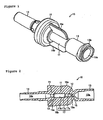
- FIGS. 1 and 2 show a liquid flow detector 10 according to this mode of embodiment, and this liquid flow detector 10 is used in order to detect the flow of a minute amount of a liquid such as a drug solution (referred to hereinbelow as "liquid") which is flowing inside tubes T (which configure the liquid supply channel according to the present invention and are shown in Figure 4 ) of a transfusion line set 20.
- liquid a liquid such as a drug solution
- the liquid flow detector 10 comprises a detector main body 11; a mobile spherical body 12 arranged inside the detector main body 11 and acting as the mobile body according to the present invention; an inflow pipe 13 provided at the upstream side of the detector main body 11 (the right-hand side in Figures 1 and 2 ; hereinafter, the upstream side of the liquid flow shall be referred to as the rear part, and the downstream side of the liquid flow shall be referred to as the front part); an outflow pipe 14 provided at the downstream side of the detector main body 11; and grip parts 15, 16a, 16b formed on the periphery of the detector main body 11.
- the detector main body 11 is cylindrical, and as shown in Figure 2 , it has formed inside it a liquid flow channel 17 comprising a liquid flow detection channel 17a, a discharge channel 17b, and an intermediate flow channel 17c positioned between the liquid flow detection channel 17a and the discharge channel 17b. Furthermore, an upstream hole 18 which links the liquid flow detection channel 17a in communication with an upstream liquid flow channel 13a formed inside the inflow pipe 13 is formed at the upstream end of the liquid flow contourion channel 17a, and a downstream hole 19 which links the discharge channel 17b in communication with a downstream liquid flow channel 14a formed inside the outflow pipe 14 is formed at the downstream end of the discharge channel 17b.
- the liquid flow detection channel 17a consists of a hole extending from front to rear with a constant diameter (1.6 mm), and it is approximately 1/3 of the length of the liquid flow channel 17 in the front to rear direction (3.0 -4.0 mm).
- the discharge channel 17b consists of a hole extending from front to rear with a constant diameter (2.0 mm), and it is approximately 2/3 of the length of the liquid flow channel 17 in the front to rear direction (7.0 - 8.0 mm).
- the intermediate flow channel 17c consists of a hole having a tapering inner peripheral surface, in which the diameter at its upstream end is the same as the diameter of the liquid flow detection channel 17a, and the diameter at its downstream end is the same as the diameter of the discharge channel 17b, and the length of the liquid flow channel 17 in the front to rear direction is set at approximately 10 -12 mm.
- the upstream hole 18 consists of a hole in which the outer periphery of the face (space) orthogonal to the flow of liquid is elliptical, and the length along the major axis of the ellipse (horizontal direction) is set at 1.2 mm, with the length along the minor axis of the ellipse (vertical direction) being set at 0.8 mm. Furthermore, a step 18a is formed between the liquid flow detection channel 17a and the upstream hole 18.
- the downstream hole 19 consists of a hole which is larger than the upstream hole 18 in which the outer periphery of the face (space) orthogonal to the flow of liquid is elliptical, and the length along the major axis of the ellipse (horizontal direction) is set at 1.8 mm, with the length along the minor axis of the ellipse (vertical direction) being set at 1.2 mm.
- a linking hole 19a which is tapered so as to become steadily narrower from the side of the discharge channel 17b moving towards the side of the downstream hole 19 is formed between the discharge channel 17b and the downstream hole 19.
- This linking hole 19a has an upstream end formed as a circle having the same diameter as the diameter of the discharge channel 17b, becoming steadily narrower as it approaches the downstream hole 19, and also it becomes an ellipse whereof the major axis in the horizontal direction is longer than the minor axis in the vertical direction.
- This detector main body 11, and the inflow pipe 13, outflow pipe 14 and grip parts 15, 16a, 16b which will be described later, are made of polycarbonate, polypropylene, or similar polymeric material.
- the mobile spherical body 12 is then arranged in the liquid flow channel 17 which is formed in this manner.
- the mobile spherical body 12 is made of polytetrafluoroethylene, which has excellent resistance to drugs, and the diameter is 1.5 nun, and the specific gravity is 2.13 - 2.22. It is also possible to use polyacetal (specific gravity 1.41-1.42) or polypropylene (specific gravity 0.90 - 0.91).
- the mobile spherical body 12 presents resistance to the flow of liquid and moves to the side of the discharge channel 17b with the flow of liquid, even if the liquid flow rate is minute.
- the mobile spherical body 12 When the mobile spherical body 12 is positioned inside the discharge channel 17b, there is a reasonable size of gap between the inner peripheral surface of the discharge channel 17b and the outer peripheral surface of the mobile spherical body 12, and therefore there is little or no resistance to the flow of liquid due to the mobile spherical body 12. Consequently, the mobile spherical body 12 remains static at the lower part of the inner peripheral surface of the discharge channel 17b, or moves steadily towards the downstream hole 19, depending on the flow rate of the liquid. In this case, the positional relationship between the mobile spherical body 12 and the downstream hole 19 is as shown in Figure 3 , even if the flow rate of liquid is high and the mobile spherical body 12 has reached the opening of the downstream hole 19.
- the mobile spherical body 12 cannot pass through the downstream hole 19 and move into the downstream liquid flow channel 14a, and only liquid passes through the downstream hole 19 and flows into the downstream liquid flow channel 14a. Furthermore, in the same way, when the liquid flow detection channel 17a is positioned lower down than the discharge channel 17b so that the mobile spherical body 12 reaches the opening of the upstream hole 18, the positional relationship between the mobile spherical body 12 and the upstream hole 18 is as shown in Figure 3 . Consequently, the mobile spherical body 12 cannot pass through the upstream hole 18 and move into the upstream liquid flow channel 13a, and liquid passes through the upstream hole 18 and flows into the liquid flow detection channel 17a.
- the inflow pipe 13 consists of a female luer in which the diameter of the upstream liquid flow channel 13a formed therein becomes steadily smaller from the opening side moving towards the side of the upstream hole 18, and a thread 13b (omitted from Figure 2 ) is formed on the outer periphery of the opening part.
- a male luer part which is attached to the tip end of a specific tube T from the plurality of tubes T can be engaged at the inflow pipe 13.
- the outflow pipe 14 consists of a male luer in which the diameter of the outer peripheral surface of the front end portion (a portion of approximately 1/3 of the whole length) becomes steadily smaller from the base end side towards the front end side of the outflow pipe 14, and a female luer part attached to the tip end of a specific tube T can be engaged at the outflow pipe 14.
- the grip part 15 is provided on the outer periphery of a portion of the detector main body 11 on the outflow pipe 14 side, and it is formed as a disc shape.
- the downstream hole 19, linking hole 19a, downstream end of the discharge channel 17b and upstream end of the downstream liquid flow channel 14a in the detector main body 11 are positioned inside this grip part 15, and the thickness of the grip part 15 corresponds to these.
- the grip parts 16a, 16b are both formed as plate shapes which project outwards from the outer peripheral surface of the detector main body 11. These grip parts 16a,16b extend in the axial direction of the detector main body 11 with an interval between each other of 180°, and the front end thereof reaches the rear surface of the grip part 15.
- the grip part 15 or grip parts 16a, 16b are gripped with the hand when the liquid flow detector 10 is operated.
- the liquid flow detector 10 configured in this way is incorporated into the transfusion line set 20 shown in Figure 4 .
- This transfusion line set 20 configures the transfusion line according to the present invention and comprises an infuser 21, a filter 22 and a flow restriction filter 23, and the liquid flow detector 10 is arranged downstream of the flow restriction filter 23.
- Each device of the transfusion line set 20 is then connected by means of specific tubes T.
- the infuser 21 is provided with an expandable liquid container and an open/close operating part for opening and closing the liquid container, and liquid is housed inside the liquid container. Then, when the outflow port of the liquid container is opened by operation of the open/close operating part, the liquid is pushed out by the force of contraction of the liquid container.
- the filter 22 absorbs foreign bodies in the liquid delivered from the infuser 21, removing them from the liquid.
- the flow rate restriction filter 23 makes the flow rate of the liquid delivered from the infuser 21, via the filter 22, constant, and it sends it to the liquid flow detector 10 on the downstream side.
- the liquid flow detector 10 allows the liquid to pass through, and is operated when the flow of liquid is to be confirmed, as required.
- the liquid which has passed through the liquid flow detector 10 is then supplied to the patient's body. That is to say, when the transfusion line set 20 is used, the downstream end of the tube T is connected to a puncture needle (not depicted) such as an indwelling needle which pierces the patient's body and remains indwelling.
- liquid flow detection channel 17a is preferably positioned higher up than the discharge channel 17b, and the mobile spherical body 12 is preferably positioned inside the discharge channel 17b.
- the mobile spherical body 12 is first of all moved to the upstream end of the liquid flow detection channel 17a by inclining the liquid flow detector 10 so that the liquid flow detection channel 17a is lower than the discharge channel 17b.
- the liquid flow detector 10 is placed on a base or the like having a horizontal surface, and the direction of flow of the liquid inside the liquid flow channel 17 is set to the horizontal. In this case, when the mobile spherical body 12 is moved inside the liquid flow detection channel 17a towards the discharge channel 17b, it is judged that the liquid is flowing properly.
- the mobile spherical body 12 is static, it is judged that the liquid is not flowing, and the necessary steps are taken. If it is judged that the liquid is flowing properly, the liquid flow detection channel 17a is preferably once again positioned higher up than the discharge channel 17b, and the mobile spherical body 12 is preferably positioned inside the discharge flow channel 17b.
- the liquid flow channel 17 comprising the liquid flow detection channel 17a, discharge channel 17b and intermediate flow channel 17c, is formed inside the detector main body 11, and the mobile spherical body 12 is arranged inside said flow channel 17.
- the diameter of the liquid flow detection channel 17a is set to be slightly greater than the diameter of the mobile spherical body 12, and the diameter of the discharge channel 17b is set to be even greater than the diameter of the liquid flow detection channel 17a Accordingly, when the mobile spherical body 12 is positioned at the upstream end of the liquid flow detection channel 17a in a state in which the liquid flow channel 17 of the detector main body 11 is horizontally positioned, the mobile spherical body 12 moves from the upstream side towards the downstream side of the liquid flow detection channel 17a when the liquid is flowing properly inside the liquid flow channel 17 from the upstream side towards the downstream side.
- the mobile spherical body 12 is positioned inside the discharge channel 17b, there is a large gap between the inner peripheral surface of the discharge channel 17b and the outer peripheral surface of the mobile spherical body 12, and therefore there is no obstruction to the flow of liquid.
- the peripheral edge parts of the upstream hole 18 and downstream hole 19 which are provided at both ends of the liquid flow channel 17 are formed as an ellipse, and therefore it is possible to prevent the mobile spherical body 12 from moving outside of the liquid flow channel 17, and also to prevent the flow of liquid stopping because of the mobile spherical body 12 coming into abutment with the peripheral edge parts of the upstream hole 18 or downstream hole 19.
- the tapering intermediate flow channel 17c is provided between the liquid flow detection channel 17a and the discharge channel 17b, and therefore it is possible to carry out a smooth operation to move the mobile spherical body 12 from the discharge channel 17b to the liquid flow detection channel 17a.
- the liquid flow detector 10 is not limited to the mode of embodiment described above, and suitable modifications can be implemented.
- the diameter of the liquid flow detection channel 17a is set at 1.6 mm
- the diameter of the mobile spherical body 12 is set at 1.5 mm, but both of these diameters may be suitably modified depending on the flow rate of the liquid. If the flow of liquid is no more than 1 ml per hour, for example, the diameter of the liquid flow detection channel 17a and the diameter of the mobile spherical body 12 are set so that the area of the minimum gap between the inner peripheral surface of the liquid flow detection channel 17a and the outer peripheral surface of the mobile spherical body 12 is even smaller.
- the diameter of the liquid flow detection channel 17a and the diameter of the mobile spherical body can be set so that the area of the minimum gap between the inner peripheral surface of the liquid flow detection channel 17a and the outer peripheral surface of the mobile spherical body 12 is slightly greater.
- the shape of the peripheral edge part of the upstream hole 18 and downstream hole 19 is made elliptical so that liquid passes through without being obstructed by the mobile spherical body 12, but the mobile spherical body 12 does not pass through; other shapes may, however, be employed instead of this.
- the mobile body is configured by the mobile spherical body 12, but a columnar body, a body in which the centre axis of two conical bodies has been placed coaxially and the tops of the two conical bodies are linked, or a body in which the centres of two facing discs are linked by a shaft, or similar can also be used instead of the mobile spherical body 12.
- the mobile body may be moved by forming the face on the upstream side of the mobile body as a recess instead of a convex surface or plane surface, and making the liquid come into contact with the recess.
- the diameter of the discharge flow channel 17b may be set so that the downstream side is larger than the upstream side, and the inner peripheral surface of the discharge channel 17b may be tapered. In this case, the intermediate flow channel 17c may be omitted.
- the structure and material of the various members making up the liquid flow detector 10, and the specific gravity etc. of the mobile spherical body 12 may be suitably modified within the technical scope of the present disclosure.
Landscapes
- Physics & Mathematics (AREA)
- Fluid Mechanics (AREA)
- Health & Medical Sciences (AREA)
- General Physics & Mathematics (AREA)
- Heart & Thoracic Surgery (AREA)
- Animal Behavior & Ethology (AREA)
- Anesthesiology (AREA)
- Biomedical Technology (AREA)
- Vascular Medicine (AREA)
- Hematology (AREA)
- Life Sciences & Earth Sciences (AREA)
- Engineering & Computer Science (AREA)
- General Health & Medical Sciences (AREA)
- Public Health (AREA)
- Veterinary Medicine (AREA)
- Infusion, Injection, And Reservoir Apparatuses (AREA)
- Measuring Volume Flow (AREA)
- Indicating Or Recording The Presence, Absence, Or Direction Of Movement (AREA)
- Investigating Or Analyzing Materials By The Use Of Magnetic Means (AREA)
Claims (6)
- Flüssigkeitsstromdetektor, der in einer Transfusionsleitung eingebaut ist, um den Strom einer Flüssigkeit in der Transfusionsleitung zu detektieren,
wobei der Flüssigkeitsstromdetektor dadurch gekennzeichnet ist, dass er mit Folgendem versehen ist:einem Detektorhauptkörper, in dem ein Flüssigkeitsstromkanal ausgebildet ist, der einen kreisförmigen Querschnitt aufweist und zwischen einem an einem stromaufwärtigen Ende gebildeten stromaufwärtigen Loch und einem an einem stromabwärtigen Ende gebildeten stromabwärtigen Loch einen Flüssigkeitsstromdetektionskanal, der auf der stromaufwärtigen Lochseite positioniert ist, und einen Ablasskanal, der auf der stromabwärtigen Lochseite positioniert ist, umfasst; undeinem mobilen Körper, der in dem Flüssigkeitsstromkanal platziert ist, sich entlang dem Strom einer Flüssigkeit in dem Flüssigkeitsstromkanal bewegt und in dem der Außenumfangsrandteil der orthogonal zu der Bewegungsrichtung verlaufenden Fläche kreisförmig ausgebildet ist;wobei der Durchmesser des Flüssigkeitsstromdetektionskanals so eingestellt ist, dass er kleiner ist als der Durchmesser des Ablasskanals und der maximale Durchmesser des Außenumfangsrandteils der orthogonal zu der Bewegungsrichtung des beweglichen Körpers verlaufenden Fläche so eingestellt ist, dass er etwas kleiner ist als der Durchmesser des Flüssigkeitsstromdetektionskanals, und weiterhin das stromaufwärtige Loch und das stromabwärtige Loch mit einer solchen Größe und Form ausgebildet sind, dass Flüssigkeit durch sie hindurch strömt, ohne von dem beweglichen Körper behindert zu werden, aber der bewegliche Körper nicht durch sie hindurchpasst. - Flüssigkeitsstromdetektor nach Anspruch 1, wobei der bewegliche Körper aus einem kugelförmigen Körper besteht.
- Flüssigkeitsstromdetektor nach Anspruch 1 oder 2, wobei ein Zwischenstromkanal, dessen Durchmesser von dem Flüssigkeitsstromdetektionskanal zum Ablasskanal kontinuierlich größer wird, zwischen dem Flüssigkeitsstromdetektionskanal und dem Ablasskanal vorgesehen ist.
- Flüssigkeitsstromdetektor nach einem der Ansprüche 1 bis 3, wobei die Form von zwischen der Größe und Form des stromaufwärtigen Lochs und des stromabwärtigen Lochs, so dass Flüssigkeit durch sie hindurch strömt, ohne von dem beweglichen Körper behindert zu werden, aber der bewegliche Körper nicht durch sie hindurchpasst, aus einer Form besteht, bei der der Umfangsrandteil des stromaufwärtigen Lochs und stromabwärtigen Lochs orthogonal zum Flüssigkeitsstrom elliptisch ist.
- Flüssigkeitsstromdetektor nach einem der Ansprüche 1 bis 4, wobei ein Zulaufrohr, das ein weibliches Luer-Teil umfasst, das eine Kommunikationsverbindung mit dem Flüssigkeitsstromkanal herstellt, mit der stromaufwärtigen Lochseite des Detektorhauptkörpers verbunden ist und ein Ablaufrohr, das ein männliches Luer-Teil umfasst, das eine Kommunikationsverbindung mit dem Flüssigkeitsstromkanal herstellt, mit der stromabwärtigen Lochseite des Detektorhauptkörpers verbunden ist.
- Transfusionsleitung mit einem Flüssigkeitsstromdetektor nach einem der Ansprüche 1 bis 5, dadurch gekennzeichnet, dass er mit einem Flüssigkeitszufuhrteil und einem Flüssigkeitszufuhrkanal, durch den eine von dem Flüssigkeitszufuhrteil zugeführte Flüssigkeit strömt, versehen ist, und der Flüssigkeitsstromdetektor in dem Flüssigkeitzufuhrkanal angeordnet ist.
Applications Claiming Priority (1)
| Application Number | Priority Date | Filing Date | Title |
|---|---|---|---|
| JP2008245141 | 2008-09-25 |
Publications (2)
| Publication Number | Publication Date |
|---|---|
| EP2168618A1 EP2168618A1 (de) | 2010-03-31 |
| EP2168618B1 true EP2168618B1 (de) | 2011-03-09 |
Family
ID=41429663
Family Applications (1)
| Application Number | Title | Priority Date | Filing Date |
|---|---|---|---|
| EP09010487A Not-in-force EP2168618B1 (de) | 2008-09-25 | 2009-08-14 | Flüssigkeitsstromdetektor und Transfusionsleitung damit |
Country Status (6)
| Country | Link |
|---|---|
| US (1) | US8061218B2 (de) |
| EP (1) | EP2168618B1 (de) |
| JP (1) | JP2010099454A (de) |
| AT (1) | ATE500858T1 (de) |
| DE (1) | DE602009000844D1 (de) |
| ES (1) | ES2362166T3 (de) |
Families Citing this family (1)
| Publication number | Priority date | Publication date | Assignee | Title |
|---|---|---|---|---|
| CN110023758B (zh) | 2016-11-24 | 2022-08-30 | 西门子医疗系统荷兰有限公司 | 用于从体液样本中分离分析物的设备、系统、方法和套件 |
Family Cites Families (9)
| Publication number | Priority date | Publication date | Assignee | Title |
|---|---|---|---|---|
| US3416371A (en) * | 1966-04-07 | 1968-12-17 | Dwyer Mfg Co F W | Flow meter with electrical read-out |
| US4486744A (en) * | 1982-08-04 | 1984-12-04 | International Business Machines Corporation | Maximum and minimum gas flow sensor |
| JPS62103520A (ja) * | 1985-10-31 | 1987-05-14 | Terumo Corp | 流量計 |
| GB2224124B (en) * | 1988-09-09 | 1992-11-11 | Gentech Int Ltd | Flow switches |
| US5462525A (en) * | 1994-06-14 | 1995-10-31 | Minimed, Inc., A Delaware Corporation | Flow sensor for an infusion pump |
| US5445622A (en) * | 1994-12-20 | 1995-08-29 | Brown; Eric W. | Flow switch device for medical applications |
| US5717137A (en) * | 1996-02-01 | 1998-02-10 | Standex International Corporation | Flow monitoring line strainer |
| US6935190B1 (en) * | 2002-04-23 | 2005-08-30 | Massachusetts Institute Of Technology | Flow rate measurement apparatus |
| FR2852690B1 (fr) | 2003-03-18 | 2006-02-03 | Debitmetre a flotteur a debit variable |
-
2009
- 2009-04-21 JP JP2009102938A patent/JP2010099454A/ja active Pending
- 2009-08-14 DE DE602009000844T patent/DE602009000844D1/de active Active
- 2009-08-14 AT AT09010487T patent/ATE500858T1/de not_active IP Right Cessation
- 2009-08-14 ES ES09010487T patent/ES2362166T3/es active Active
- 2009-08-14 EP EP09010487A patent/EP2168618B1/de not_active Not-in-force
- 2009-08-17 US US12/542,020 patent/US8061218B2/en active Active
Also Published As
| Publication number | Publication date |
|---|---|
| JP2010099454A (ja) | 2010-05-06 |
| ES2362166T3 (es) | 2011-06-29 |
| US8061218B2 (en) | 2011-11-22 |
| DE602009000844D1 (de) | 2011-04-21 |
| ATE500858T1 (de) | 2011-03-15 |
| US20100071478A1 (en) | 2010-03-25 |
| EP2168618A1 (de) | 2010-03-31 |
Similar Documents
| Publication | Publication Date | Title |
|---|---|---|
| US7824364B2 (en) | Liquid-mixing infusor | |
| CN1332722C (zh) | 三通活栓以及采用该三通活栓的输液管装置或输血管装置 | |
| JP4267206B2 (ja) | 貯蔵器接続具 | |
| AU2014334836B2 (en) | Sampling port | |
| TWI503115B (zh) | 提供一流體傳輸模組之方法、用於流體傳輸系統中的連接器、附接連接器之方法、及製作連接器之方法 | |
| US9052025B2 (en) | Bidirectional duckbill valve apparatus and a method for its use | |
| US5788215A (en) | Medical intravenous administration line connectors having a luer or pressure activated valve | |
| US20160346485A1 (en) | Apparatus and methods for intravenous gas elimination | |
| US7487800B2 (en) | Flow restriction | |
| JPH04246370A (ja) | 心臓血管組立体 | |
| CN102548606A (zh) | 转动型医用多路开关 | |
| JP6293787B2 (ja) | 製品流体の分注方法及び針キット | |
| EP2168618B1 (de) | Flüssigkeitsstromdetektor und Transfusionsleitung damit | |
| US8132470B2 (en) | Fluid flow detector having a mobile body moving between a detection channel and a discharge channel | |
| US20140216557A1 (en) | Connecting device with a clamping device for connecting to an arrangement for closing flow paths and monitoring the status of the clamping device and method for same | |
| DE69101654T2 (de) | Detektor für den Abfluss einer ersten Flüssigkeit im Kreislauf einer zweiten Flüssigkeit. | |
| WO2001026550A1 (en) | A device for underpressuring and collection and dosage liquid samples | |
| KR20170111287A (ko) | 수액세트용 유량 조절장치 | |
| JP5814227B2 (ja) | 液体投与回路 | |
| JP2005334280A (ja) | 輸液チューブおよび輸液チューブセット | |
| KR101706147B1 (ko) | 수액세트용 유량 조절장치 | |
| JPWO2012002313A1 (ja) | 輸液チューブおよび輸液チューブセット | |
| JP2017086649A (ja) | 輸液針および針抜け検知システム | |
| CN120900044A (zh) | 一种三插式造血干细胞输注器 | |
| CN113521443A (zh) | 一种针刺式顺序切换通道的连续输液器 |
Legal Events
| Date | Code | Title | Description |
|---|---|---|---|
| PUAI | Public reference made under article 153(3) epc to a published international application that has entered the european phase |
Free format text: ORIGINAL CODE: 0009012 |
|
| AK | Designated contracting states |
Kind code of ref document: A1 Designated state(s): AT BE BG CH CY CZ DE DK EE ES FI FR GB GR HR HU IE IS IT LI LT LU LV MC MK MT NL NO PL PT RO SE SI SK SM TR |
|
| AX | Request for extension of the european patent |
Extension state: AL BA RS |
|
| 17P | Request for examination filed |
Effective date: 20100721 |
|
| GRAP | Despatch of communication of intention to grant a patent |
Free format text: ORIGINAL CODE: EPIDOSNIGR1 |
|
| GRAS | Grant fee paid |
Free format text: ORIGINAL CODE: EPIDOSNIGR3 |
|
| GRAA | (expected) grant |
Free format text: ORIGINAL CODE: 0009210 |
|
| AK | Designated contracting states |
Kind code of ref document: B1 Designated state(s): AT BE BG CH CY CZ DE DK EE ES FI FR GB GR HR HU IE IS IT LI LT LU LV MC MK MT NL NO PL PT RO SE SI SK SM TR |
|
| REG | Reference to a national code |
Ref country code: GB Ref legal event code: FG4D |
|
| REG | Reference to a national code |
Ref country code: CH Ref legal event code: EP |
|
| REG | Reference to a national code |
Ref country code: IE Ref legal event code: FG4D |
|
| REG | Reference to a national code |
Ref country code: CH Ref legal event code: NV Representative=s name: DR. GRAF & PARTNER AG INTELLECTUAL PROPERTY |
|
| REG | Reference to a national code |
Ref country code: NL Ref legal event code: T3 |
|
| REF | Corresponds to: |
Ref document number: 602009000844 Country of ref document: DE Date of ref document: 20110421 Kind code of ref document: P |
|
| REG | Reference to a national code |
Ref country code: DE Ref legal event code: R096 Ref document number: 602009000844 Country of ref document: DE Effective date: 20110421 |
|
| REG | Reference to a national code |
Ref country code: ES Ref legal event code: FG2A Ref document number: 2362166 Country of ref document: ES Kind code of ref document: T3 Effective date: 20110629 |
|
| PG25 | Lapsed in a contracting state [announced via postgrant information from national office to epo] |
Ref country code: SE Free format text: LAPSE BECAUSE OF FAILURE TO SUBMIT A TRANSLATION OF THE DESCRIPTION OR TO PAY THE FEE WITHIN THE PRESCRIBED TIME-LIMIT Effective date: 20110309 Ref country code: LV Free format text: LAPSE BECAUSE OF FAILURE TO SUBMIT A TRANSLATION OF THE DESCRIPTION OR TO PAY THE FEE WITHIN THE PRESCRIBED TIME-LIMIT Effective date: 20110309 Ref country code: LT Free format text: LAPSE BECAUSE OF FAILURE TO SUBMIT A TRANSLATION OF THE DESCRIPTION OR TO PAY THE FEE WITHIN THE PRESCRIBED TIME-LIMIT Effective date: 20110309 Ref country code: GR Free format text: LAPSE BECAUSE OF FAILURE TO SUBMIT A TRANSLATION OF THE DESCRIPTION OR TO PAY THE FEE WITHIN THE PRESCRIBED TIME-LIMIT Effective date: 20110610 Ref country code: NO Free format text: LAPSE BECAUSE OF FAILURE TO SUBMIT A TRANSLATION OF THE DESCRIPTION OR TO PAY THE FEE WITHIN THE PRESCRIBED TIME-LIMIT Effective date: 20110609 Ref country code: HR Free format text: LAPSE BECAUSE OF FAILURE TO SUBMIT A TRANSLATION OF THE DESCRIPTION OR TO PAY THE FEE WITHIN THE PRESCRIBED TIME-LIMIT Effective date: 20110309 |
|
| LTIE | Lt: invalidation of european patent or patent extension |
Effective date: 20110309 |
|
| PG25 | Lapsed in a contracting state [announced via postgrant information from national office to epo] |
Ref country code: AT Free format text: LAPSE BECAUSE OF FAILURE TO SUBMIT A TRANSLATION OF THE DESCRIPTION OR TO PAY THE FEE WITHIN THE PRESCRIBED TIME-LIMIT Effective date: 20110309 Ref country code: SI Free format text: LAPSE BECAUSE OF FAILURE TO SUBMIT A TRANSLATION OF THE DESCRIPTION OR TO PAY THE FEE WITHIN THE PRESCRIBED TIME-LIMIT Effective date: 20110309 Ref country code: CY Free format text: LAPSE BECAUSE OF FAILURE TO SUBMIT A TRANSLATION OF THE DESCRIPTION OR TO PAY THE FEE WITHIN THE PRESCRIBED TIME-LIMIT Effective date: 20110309 Ref country code: FI Free format text: LAPSE BECAUSE OF FAILURE TO SUBMIT A TRANSLATION OF THE DESCRIPTION OR TO PAY THE FEE WITHIN THE PRESCRIBED TIME-LIMIT Effective date: 20110309 Ref country code: BG Free format text: LAPSE BECAUSE OF FAILURE TO SUBMIT A TRANSLATION OF THE DESCRIPTION OR TO PAY THE FEE WITHIN THE PRESCRIBED TIME-LIMIT Effective date: 20110609 |
|
| PG25 | Lapsed in a contracting state [announced via postgrant information from national office to epo] |
Ref country code: BE Free format text: LAPSE BECAUSE OF FAILURE TO SUBMIT A TRANSLATION OF THE DESCRIPTION OR TO PAY THE FEE WITHIN THE PRESCRIBED TIME-LIMIT Effective date: 20110309 |
|
| PG25 | Lapsed in a contracting state [announced via postgrant information from national office to epo] |
Ref country code: EE Free format text: LAPSE BECAUSE OF FAILURE TO SUBMIT A TRANSLATION OF THE DESCRIPTION OR TO PAY THE FEE WITHIN THE PRESCRIBED TIME-LIMIT Effective date: 20110309 Ref country code: PT Free format text: LAPSE BECAUSE OF FAILURE TO SUBMIT A TRANSLATION OF THE DESCRIPTION OR TO PAY THE FEE WITHIN THE PRESCRIBED TIME-LIMIT Effective date: 20110711 |
|
| PG25 | Lapsed in a contracting state [announced via postgrant information from national office to epo] |
Ref country code: IS Free format text: LAPSE BECAUSE OF FAILURE TO SUBMIT A TRANSLATION OF THE DESCRIPTION OR TO PAY THE FEE WITHIN THE PRESCRIBED TIME-LIMIT Effective date: 20110709 Ref country code: SK Free format text: LAPSE BECAUSE OF FAILURE TO SUBMIT A TRANSLATION OF THE DESCRIPTION OR TO PAY THE FEE WITHIN THE PRESCRIBED TIME-LIMIT Effective date: 20110309 Ref country code: RO Free format text: LAPSE BECAUSE OF FAILURE TO SUBMIT A TRANSLATION OF THE DESCRIPTION OR TO PAY THE FEE WITHIN THE PRESCRIBED TIME-LIMIT Effective date: 20110309 Ref country code: CZ Free format text: LAPSE BECAUSE OF FAILURE TO SUBMIT A TRANSLATION OF THE DESCRIPTION OR TO PAY THE FEE WITHIN THE PRESCRIBED TIME-LIMIT Effective date: 20110309 |
|
| PGFP | Annual fee paid to national office [announced via postgrant information from national office to epo] |
Ref country code: ES Payment date: 20110826 Year of fee payment: 3 |
|
| PG25 | Lapsed in a contracting state [announced via postgrant information from national office to epo] |
Ref country code: MT Free format text: LAPSE BECAUSE OF FAILURE TO SUBMIT A TRANSLATION OF THE DESCRIPTION OR TO PAY THE FEE WITHIN THE PRESCRIBED TIME-LIMIT Effective date: 20110309 |
|
| PLBE | No opposition filed within time limit |
Free format text: ORIGINAL CODE: 0009261 |
|
| STAA | Information on the status of an ep patent application or granted ep patent |
Free format text: STATUS: NO OPPOSITION FILED WITHIN TIME LIMIT |
|
| 26N | No opposition filed |
Effective date: 20111212 |
|
| PG25 | Lapsed in a contracting state [announced via postgrant information from national office to epo] |
Ref country code: PL Free format text: LAPSE BECAUSE OF FAILURE TO SUBMIT A TRANSLATION OF THE DESCRIPTION OR TO PAY THE FEE WITHIN THE PRESCRIBED TIME-LIMIT Effective date: 20110309 Ref country code: DK Free format text: LAPSE BECAUSE OF FAILURE TO SUBMIT A TRANSLATION OF THE DESCRIPTION OR TO PAY THE FEE WITHIN THE PRESCRIBED TIME-LIMIT Effective date: 20110309 |
|
| PG25 | Lapsed in a contracting state [announced via postgrant information from national office to epo] |
Ref country code: MC Free format text: LAPSE BECAUSE OF NON-PAYMENT OF DUE FEES Effective date: 20110831 |
|
| REG | Reference to a national code |
Ref country code: DE Ref legal event code: R097 Ref document number: 602009000844 Country of ref document: DE Effective date: 20111212 |
|
| REG | Reference to a national code |
Ref country code: IE Ref legal event code: MM4A |
|
| PG25 | Lapsed in a contracting state [announced via postgrant information from national office to epo] |
Ref country code: IE Free format text: LAPSE BECAUSE OF NON-PAYMENT OF DUE FEES Effective date: 20110814 |
|
| PG25 | Lapsed in a contracting state [announced via postgrant information from national office to epo] |
Ref country code: MK Free format text: LAPSE BECAUSE OF FAILURE TO SUBMIT A TRANSLATION OF THE DESCRIPTION OR TO PAY THE FEE WITHIN THE PRESCRIBED TIME-LIMIT Effective date: 20110309 |
|
| PG25 | Lapsed in a contracting state [announced via postgrant information from national office to epo] |
Ref country code: SM Free format text: LAPSE BECAUSE OF FAILURE TO SUBMIT A TRANSLATION OF THE DESCRIPTION OR TO PAY THE FEE WITHIN THE PRESCRIBED TIME-LIMIT Effective date: 20110309 |
|
| PG25 | Lapsed in a contracting state [announced via postgrant information from national office to epo] |
Ref country code: LU Free format text: LAPSE BECAUSE OF NON-PAYMENT OF DUE FEES Effective date: 20110814 |
|
| PG25 | Lapsed in a contracting state [announced via postgrant information from national office to epo] |
Ref country code: TR Free format text: LAPSE BECAUSE OF FAILURE TO SUBMIT A TRANSLATION OF THE DESCRIPTION OR TO PAY THE FEE WITHIN THE PRESCRIBED TIME-LIMIT Effective date: 20110309 |
|
| REG | Reference to a national code |
Ref country code: ES Ref legal event code: FD2A Effective date: 20131018 |
|
| PG25 | Lapsed in a contracting state [announced via postgrant information from national office to epo] |
Ref country code: ES Free format text: LAPSE BECAUSE OF NON-PAYMENT OF DUE FEES Effective date: 20120815 Ref country code: HU Free format text: LAPSE BECAUSE OF FAILURE TO SUBMIT A TRANSLATION OF THE DESCRIPTION OR TO PAY THE FEE WITHIN THE PRESCRIBED TIME-LIMIT Effective date: 20110309 |
|
| REG | Reference to a national code |
Ref country code: FR Ref legal event code: PLFP Year of fee payment: 8 |
|
| REG | Reference to a national code |
Ref country code: FR Ref legal event code: PLFP Year of fee payment: 9 |
|
| REG | Reference to a national code |
Ref country code: GB Ref legal event code: 732E Free format text: REGISTERED BETWEEN 20180118 AND 20180124 |
|
| REG | Reference to a national code |
Ref country code: CH Ref legal event code: NV Representative=s name: SERVOPATENT GMBH, CH Ref country code: CH Ref legal event code: PUE Owner name: KPR U.S., LLC, US Free format text: FORMER OWNER: TYCO HEALTHCARE GROUP LP, US |
|
| REG | Reference to a national code |
Ref country code: FR Ref legal event code: PLFP Year of fee payment: 10 |
|
| REG | Reference to a national code |
Ref country code: FR Ref legal event code: CD Owner name: COVIDIEN LP, US Effective date: 20181012 |
|
| REG | Reference to a national code |
Ref country code: CH Ref legal event code: PCAR Free format text: NEW ADDRESS: WANNERSTRASSE 9/1, 8045 ZUERICH (CH) |
|
| PGFP | Annual fee paid to national office [announced via postgrant information from national office to epo] |
Ref country code: NL Payment date: 20200826 Year of fee payment: 12 |
|
| PGFP | Annual fee paid to national office [announced via postgrant information from national office to epo] |
Ref country code: DE Payment date: 20200827 Year of fee payment: 12 Ref country code: FR Payment date: 20200825 Year of fee payment: 12 Ref country code: GB Payment date: 20200827 Year of fee payment: 12 |
|
| PGFP | Annual fee paid to national office [announced via postgrant information from national office to epo] |
Ref country code: IT Payment date: 20200821 Year of fee payment: 12 Ref country code: CH Payment date: 20200903 Year of fee payment: 12 |
|
| REG | Reference to a national code |
Ref country code: DE Ref legal event code: R119 Ref document number: 602009000844 Country of ref document: DE |
|
| REG | Reference to a national code |
Ref country code: CH Ref legal event code: PL |
|
| REG | Reference to a national code |
Ref country code: NL Ref legal event code: MM Effective date: 20210901 |
|
| GBPC | Gb: european patent ceased through non-payment of renewal fee |
Effective date: 20210814 |
|
| PG25 | Lapsed in a contracting state [announced via postgrant information from national office to epo] |
Ref country code: LI Free format text: LAPSE BECAUSE OF NON-PAYMENT OF DUE FEES Effective date: 20210831 Ref country code: CH Free format text: LAPSE BECAUSE OF NON-PAYMENT OF DUE FEES Effective date: 20210831 |
|
| PG25 | Lapsed in a contracting state [announced via postgrant information from national office to epo] |
Ref country code: NL Free format text: LAPSE BECAUSE OF NON-PAYMENT OF DUE FEES Effective date: 20210901 |
|
| PG25 | Lapsed in a contracting state [announced via postgrant information from national office to epo] |
Ref country code: IT Free format text: LAPSE BECAUSE OF NON-PAYMENT OF DUE FEES Effective date: 20210814 Ref country code: GB Free format text: LAPSE BECAUSE OF NON-PAYMENT OF DUE FEES Effective date: 20210814 Ref country code: FR Free format text: LAPSE BECAUSE OF NON-PAYMENT OF DUE FEES Effective date: 20210831 Ref country code: DE Free format text: LAPSE BECAUSE OF NON-PAYMENT OF DUE FEES Effective date: 20220301 |