EP2166913B1 - Reinigungsvorrichtung mit motorbetriebenem endlosband - Google Patents
Reinigungsvorrichtung mit motorbetriebenem endlosband Download PDFInfo
- Publication number
- EP2166913B1 EP2166913B1 EP08763102.4A EP08763102A EP2166913B1 EP 2166913 B1 EP2166913 B1 EP 2166913B1 EP 08763102 A EP08763102 A EP 08763102A EP 2166913 B1 EP2166913 B1 EP 2166913B1
- Authority
- EP
- European Patent Office
- Prior art keywords
- head
- belt
- housing
- roller
- rollers
- Prior art date
- Legal status (The legal status is an assumption and is not a legal conclusion. Google has not performed a legal analysis and makes no representation as to the accuracy of the status listed.)
- Active
Links
Images


Classifications
-
- A—HUMAN NECESSITIES
- A47—FURNITURE; DOMESTIC ARTICLES OR APPLIANCES; COFFEE MILLS; SPICE MILLS; SUCTION CLEANERS IN GENERAL
- A47L—DOMESTIC WASHING OR CLEANING; SUCTION CLEANERS IN GENERAL
- A47L11/00—Machines for cleaning floors, carpets, furniture, walls, or wall coverings
- A47L11/34—Machines for treating carpets in position by liquid, foam, or vapour, e.g. by steam
-
- A—HUMAN NECESSITIES
- A47—FURNITURE; DOMESTIC ARTICLES OR APPLIANCES; COFFEE MILLS; SPICE MILLS; SUCTION CLEANERS IN GENERAL
- A47L—DOMESTIC WASHING OR CLEANING; SUCTION CLEANERS IN GENERAL
- A47L11/00—Machines for cleaning floors, carpets, furniture, walls, or wall coverings
- A47L11/29—Floor-scrubbing machines characterised by means for taking-up dirty liquid
-
- A—HUMAN NECESSITIES
- A47—FURNITURE; DOMESTIC ARTICLES OR APPLIANCES; COFFEE MILLS; SPICE MILLS; SUCTION CLEANERS IN GENERAL
- A47L—DOMESTIC WASHING OR CLEANING; SUCTION CLEANERS IN GENERAL
- A47L11/00—Machines for cleaning floors, carpets, furniture, walls, or wall coverings
- A47L11/40—Parts or details of machines not provided for in groups A47L11/02 - A47L11/38, or not restricted to one of these groups, e.g. handles, arrangements of switches, skirts, buffers, levers
- A47L11/4036—Parts or details of the surface treating tools
- A47L11/4047—Wound-up or endless cleaning belts
Definitions
- the present invention relates to cleaning apparatus and, more particularly, to apparatus having a motor-driven endless belt able to remove fluids and other contaminants from a surface to be cleaned, such as a floor.
- a typical mop includes a head attached to the end of a handle together with a squeezing mechanism that is used in conjunction with a water bucket to assist in squeezing dirty water out of the mop head.
- the problem with this prior art cleaning technology and method is that the mop head is rinsed in dirty water, requiring the water in the bucket to be changed frequently and thus making inefficient use of both water and detergent.
- prior art systems often leave the cleaned surface wet for a period of time which is longer than desired.
- Cleaning apparatus may incorporate the use of electric motors to power components such as rotating cleaning members (for instance brushes or pads) which are trailed by vacuum suction devices that provide means for picking up dirty water which has been produced by the rotating brushes scrubbing up dirt with the water provided by the machine.
- rotating cleaning members for instance brushes or pads
- vacuum suction devices that provide means for picking up dirty water which has been produced by the rotating brushes scrubbing up dirt with the water provided by the machine.
- the cleaning members can be interchanged readily, depending for example upon whether it is desired to use the machine for scrubbing, polishing or drying a surface.
- US Patent No. 3 945 078 describes a machine with an open bottom from which a lower run of an endless fabric belt projects downwardly, this belt passing around a large drive roller and several idler rollers.
- One of the idler rollers is spring-loaded for tensioning the belt and mounted in a reservoir for water or other liquid into which the upper run of the belt dips before passing through a wringer constituted by a further roller pair.
- the drive roller is hollow and driven by a motor supported in its interior by an axle traversing one of the end faces of that roller.
- Drawbacks of this machine include the difficulty in replacing the belt, and in particular the necessity to release the spring-loaded tensioning roller when replacing the belt. A large number of rollers are required, increasing manufacturing costs.
- the dirty liquid wrung from the belt back drains into the reservoir of rinsing water, and due to the lower run of the belt supporting the machine, the machine must be inverted to examine the condition of the belt.
- US2006010626 describes a floor cleaning apparatus with a cleaning head to which parallel rollers mounted, including a motor-driven roller.
- An endless cleaning belt is disposed about the rollers of the cleaning head, and pinched between the driven roller and independently mounted spring-biased pinch roller.
- the belt may be pinched between more than one housing-mounted roller and head-mounted roller pair. Also, the belt may be pinched at two or more angular positions on a housing-mounted roller by respective head-mounted rollers, or vice versa at two or more angular positions on a head-mounted roller by respective housing-mounted rollers.
- each of the head-mounted rollers engages an inner face of the belt.
- at least one head-mounted roller may engage an outer face of the belt.
- the drive means preferably comprises a rotary motor mounted to the cleaning head for rotating the driven head-mounted roller.
- the drive means may include a surface-engaging wheel rotated by movement of the apparatus.
- the belt is preferably squeezed between the housing-mounted roller and the driven head-mounted roller.
- the rotary motor is mounted within the driven head-mounted roller.
- the housing and the cleaning head preferably further include electrical couplings connected in the operating position to supply power to the motor and separated in the released position.
- the housing-mounted roller deflects the belt from a line tangentially connecting the periphery of two adjacent head-mounted rollers to tension the belt.
- Each of the head-mounted rollers preferably engages an inner face of the belt.
- the cleaning head is demountably coupled to the housing by cooperating manually releasable connectors on the cleaning head and housing, allowing the cleaning head to be separated from the housing without the use of tools for the removal or replacement of the belt.
- an element such as a hinge may connect the cleaning head and housing in a manner allowing sufficient relative movement from the operating position for removal or fitting of the belt.
- the apparatus preferably further includes synchronising means for synchronising the peripheral speeds the housing-mounted roller and one of the head-mounted rollers between which the belt is squeezed in the operating position.
- the synchronising means comprises a meshed gear pair, each gear rotationally fast with a respective one of the rollers.
- the apparatus further includes at least one wheel fixed to the housing for supporting the apparatus upon the surface, the head-mounted rollers include first and second head-mounted rollers, with a lower run of the belt for engaging the surface supported therebetween.
- the cleaning head is mounted to and projects from a forward end of the housing, an upper run of the belt extends acutely to the lower run and is supported between the drive roller and a forwardmost one of the first and second head-mounted rollers.
- the apparatus preferably further includes a second reservoir, a nozzle for receiving liquid from the second reservoir and spraying the liquid over the upper run and flow control means for controlling the flow of liquid to the nozzle.
- the flow control means may be a valve or a pump.
- the apparatus preferably further includes a handle connected to the housing to pivot about a first axis generally parallel to roller axes, and about a second axis generally perpendicular to the first axis for allowing the apparatus to be steered.
- the second reservoir, nozzle and flow control means are preferably fixed to the handle.
- Switch means are preferably mounted on the end of the handle for operating the motor and the flow control means.
- a trigger is provided for operating the flow control means and a switch for operating the motor.
- the trigger may have a two-stage operation such that initial depression of the trigger operates the motor and further depression of the trigger operates the flow control means.
- the belt may be tensioned by cooperation between more than one housing-mounted roller and the two adjacent head-mounted rollers.
- This alternative embodiment may be used, for example, for polishing a.floor
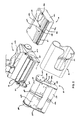
- the cleaning apparatus includes a base 1 supported at the rear by wheels 2 on either side thereof and at the front by an endless absorbent belt 3. Pivotally connected to the base 1 is a handle assembly 4 including an elongate shaft 5 extending to a handgrip 6. Adjacent the handgrip 6 is a trigger 7. The handle assembly 4 further includes a washing liquid reservoir 8 and a battery enclosure 9. A conduit 10 leads downward from the enclosure 9 to a nozzle 11 located above the belt 3.
- the base 1 includes a housing 12 having a cavity 27 in which a contaminated liquid reservoir 13 is received.
- An elongate housing-mounted wringer roller 14 is mounted to the housing 12 above the contaminated liquid reservoir 13, extending transversely and supported by journals at both ends.
- a driven gear 15 is rotationally fast with the wringer roller 14 at one end thereof.
- the handle assembly 4 includes a handle body 4a connected by an articulated joint 16 at its lower end to the housing 12.
- the joint 16 is connected at its proximal end by transversely-aligned pivot 17 to a central part of the housing 12.
- a circular collar 18 At the distal end of the joint 16 is a circular collar 18 that engages a ring portion 19 formed on the handle body 4a allowing the handle body 4a to pivot relative thereto about the common axis 20 of the collar 18 and ring 19.
- This axis 20 is perpendicular to the transverse axis of the pivot 17 for allowing the base 1 to be steered.
- the cavity 27 opens rearwardly between the wheels 2, and the contaminated liquid reservoir 13 is slidably received therein allowing it to be removed for emptying.
- the contaminated liquid reservoir 13 includes transparent front and rear walls 13a, 13b, side walls 13c, base wall 13d and top wall 13e.
- a channel 27 extends substantially along the width of the top wall 13e and drains, via a central portion 28, to an inlet aperture 29 leading into the reservoir 13.
- An elongate resilient wiper 30 is mounted to the reservoir 13 and engages the length of the wringer roller 14.
- the contaminated liquid reservoir 13 further includes an electrical coupling 31 connected to a liquid level sensor (not shown) for actuating a level warning indicator lamp 65 mounted to the top of the housing 12.
- a closure 32 closes an outlet for emptying the reservoir.
- a cleaning head 21 is releasably mounted to the front of the housing 12 and incl,udes three elongate and substantially parallel cylindrical head-mounted rollers comprising: drive roller 22, front roller 23 and rear roller 24.
- the head-mounted rollers 22-24 are supported for rotation at opposing ends in journals (not shown) fixed in the opposing end plates 25a, 25b which are joined by member 26.
- the drive roller 22 encloses a rotary electric motor 33 drivingly connected to a reduction gearbox 34 and to a torque rod 35 which is in turn fixed to the end plate 25b of the head 21 to prevent rotation of the motor and gear box 34.
- Opposing ends of the drive roller 22 are supported in bearings 36a, 36b.
- a gearbox output shaft 37 is rotationally fast with the driven roller 22 and with a drive gear 38, which in use engages the driven gear 15 for synchronising the peripheral speeds of the driven head roller 22 and the wringer roller 14.
- Electrical coupling parts 41 a and 41 b are fixed to the end plate 25b of cleaning head 21 and housing 12 respectively for supplying power to the motor 33, when the head 21 is connected.
- a guide channel 39 in a central part of the driven roller 22 extends circumferentially below its substantially cylindrical outer surface and receives a rib 41 which extends continuously around an inner face of the belt 3.
- Both front roller 23 and rear roller 24 also have respective guide channels 42, 43 aligned with the guide channel 39 for cooperating with the circumferential rib 41 to retain the belt 3 in its correct transverse position in use.
- a lower run 44 of the belt 3 is supported between the front roller 23 and rear roller 24 at the front of the apparatus and provides the primary area for contacting the surface to be cleaned.
- An exposed upper run 45 of the belt 3 extends acutely to the lower run 44 and is supported between the drive roller 22 and front roller 23.
- each of the end plates 25a, 25b Fixed on each of the end plates 25a, 25b are nubs 46 which are received in respective recesses 47 in the housing 12 and which cooperate with a manually releasable connector 48 on the head 21 for fastening the head 21 to the housing 12.
- the connector 48 includes a lever 49 pivotally mounted to the end plate 25b and having a tongue (not shown) and spring (not shown) which biases the lever 49 such that the tongue is received in the aperture 50 in the housing 12.
- a cooperating lock member (not shown) is mounted to the opposing end plate 25a, and has a respective tongue biased to engage in the opposing aperture 51.
- a rod (not shown) extends between the lever 49 and lock member for releasing both connectors simultaneously.
- the belt 3 may be changed when worn, or to provide a belt for a particular operation such as coarse scrubbing, fine polishing or absorbing liquid.
- the belt 3 is inserted over the cleaning head 21 with the channels 39, 42, 43 receiving the circumferential rib 41.
- the head 21 and belt 3 are then connected to the housing 12 by the cooperating nubs 46 and recesses 47, and the connector 48.
- this operating position shown in Figs. 1 and 4
- the belt 3 is pinched between the wringer roller 14 and the drive roller 22 to squeeze liquid and contaminants from the belt 3 into the reservoir 13. This pinching action also provides good traction for rotating the belt.
- the wringer roller 14 deflects the belt 3 inwardly from the line 52 tangential to the adjacent drive roller 22 and rear roller 24 to tension the belt 3, thereby avoiding the need for a separate tensioning device.
- the washing liquid reservoir 8 is demountable from the handle assembly 4 and includes a closure 55 at its upper end and a self-closing reservoir valve 56 at its lower end, allowing the reservoir 8 to be removed for filling with water and/or detergent.
- the reservoir valve 56 is opened by a stem 57 which communicates with a flexible and resilient tube 58 which extends down behind the batteries 59 and through the conduit 10 to the nozzle 11.
- the liquid flow from the nozzle 11 is controlled by a valve 60 operated through a rod 61 connected to the trigger 7.
- the valve 60 includes a pinch block 66 abutting the outer wall of the tube 58 fixed to a mount 67 that is connected by a pivot 68 to the inner wall of the enclosure 9.
- a tension spring 69 connected between the mount 67 and the enclosure 9 tends to rotate the mount 67 to close the valve, pinching the tube 58 between the block 66 and the fixture 71.
- the valve 60 is held open by a slider 70 which engages the mount 67.
- the slider 70 is connected to one end of the rod 61.
- the pivotally-mounted trigger 7 is connected via a rocker 62 to the rod 61, allowing the trigger 7 to be pulled to open the valve 60.
- the handgrip 6 further includes a switch 63 for controlling operation of the motor 33.
- the trigger is operated with the handle assembly 4 upright as shown in Fig. 2 to apply a spray evenly across the width of the upper run 45.
- the cleaning liquid may be applied preferentially to one or other side of the belt 3.
- the handle assembly is inclined from the upright and in this position operating the trigger directs a spray onto the surface to be cleaned, as desired.
Landscapes
- Cleaning By Liquid Or Steam (AREA)
Claims (14)
- Reinigungsvorrichtung für das Reinigen einer Fläche, die aufweist:ein Gehäuse (12);eine gehäusemontierte Rolle (14), die am Gehäuse montiert ist;einen Reinigungskopf (21), der lösbar mit dem Gehäuse verbunden ist;eine Vielzahl von kopfmontierten Rollen (22, 23, 24), die am Reinigungskopf montiert sind;ein Antriebsmittel (33, 34, 35), das funktionell mit mindestens einer angetriebenen der kopfmontierten Rollen (22) für eine Drehung der kopfmontierten Rolle (22) verbunden ist; undein Endlosband (3), das für eine Drehung um die kopfmontierten Rollen gestützt wird, wobei das Band zwischen der gehäusemontierten Rolle (14) und der angetriebenen kopfmontierten Rolle (22) zusammengedrückt wird, dadurch gekennzeichnet, dass in einer Betriebsposition die gehäusemontierte Rolle (14) das Band von einer Linie tangential zur angetriebenen kopfmontierten Rolle (22) und einer benachbarten der kopfmontierten Rollen ablenkt, um das Band zu spannen, und wobei der Reinigungskopf relativ zum Gehäuse aus der Betriebsposition in eine Freigabeposition beweglich ist, in der die Bandspannung entlastet wird, um das Band zu entfernen.
- Reinigungsvorrichtung nach Anspruch 1, bei der
das Gehäuse (12) einen ersten Behälter (13) aufnimmt;
das Endlosband (3) absorbierend ist und das Band zwischen der gehäusemontierten Rolle (14) und der angetriebenen kopfmontierten Rolle zusammengedrückt wird, um Flüssigkeit und Verunreinigungen aus dem Band in den ersten Behälter auszuquetschen. - Reinigungsvorrichtung nach Anspruch 1 oder Anspruch 2, bei der das Antriebsmittel (33, 34, 35) einen Rotationsmotor (33) aufweist, der am Reinigungskopf für eine Drehung der angetriebenen kopfmontierten Rolle montiert ist.
- Reinigungsvorrichtung nach Anspruch 3, bei der der Rotationsmotor innerhalb der angetriebenen kopfmontierten Rolle montiert ist.
- Reinigungsvorrichtung nach Anspruch 3 oder Anspruch 4, bei der das Gehäuse und der Reinigungskopf außerdem elektrische Kupplungen umfassen, die in der Betriebsposition eine Verbindung herstellen, um dem Rotationsmotor (33) Strom zuzuführen, und die in der Freigabeposition getrennt sind.
- Reinigungsvorrichtung nach einem der Ansprüche 1 bis 5, bei der eine jede der kopfmontierten Rollen mit einer Innenfläche des Bandes in Anlage kommt.
- Reinigungsvorrichtung nach einem der Ansprüche 1 bis 6, bei der der Reinigungskopf demontierbar mit dem Gehäuse verbunden ist, indem manuell lösbare Verbindungsstücke am Reinigungskopf und Gehäuse zusammenwirken.
- Reinigungsvorrichtung nach einem der Ansprüche 1 bis 7, die außerdem ein Synchronisiermittel (15, 38) für das Synchronisieren der Umfangsgeschwindigkeiten der gehäusemontierten Rolle und der angetriebenen kopfmontierten Rolle umfasst, zwischen denen das Band in der Betriebsposition ausgequetscht wird.
- Reinigungsvorrichtung nach Anspruch 8, bei der das Synchronisiermittel ein in Eingriff kommendes Zahnradpaar (15, 38) aufweist, wobei ein jedes Zahnrad rotatorisch mit einer entsprechenden von gehäusemontierter Rolle und angetriebener kopfmontierter Rolle unbeweglich ist.
- Reinigungsvorrichtung nach einem der Ansprüche 1 bis 9, die außerdem mindestens ein Rad (2) umfasst, das am Gehäuse für das Stützen der Vorrichtung auf der Oberfläche befestigt ist, wobei die kopfmontierten Rollen eine erste und zweite kopfmontierte Rolle (23, 24) umfassen, wobei ein unterer Strang (44) des Bandes für ein Berühren der Oberfläche dazwischen gestützt wird.
- Reinigungsvorrichtung nach Anspruch 10, bei der der Reinigungskopf an einem vorderen Ende des Gehäuses montiert ist und daraus vorsteht, wobei sich ein oberer Strang (45) des Bandes spitzwinkelig zum unteren Strang erstreckt und zwischen der Antriebsrolle und einer vordersten (23) von erster und zweiter kopfmontierter Rolle gestützt wird.
- Reinigungsvorrichtung nach einem der Ansprüche 1 bis 11, die außerdem umfasst: einen zweiten Behälter (9); eine Düse (11) für das Aufnehmen von Flüssigkeit aus dem zweiten Behälter und das Sprühen der Flüssigkeit über das Band (3); und ein Durchflussregelmittel (60) für das Steuern des Flüssigkeitsstromes zur Düse.
- Reinigungsvorrichtung nach Anspruch 12, die außerdem einen Griff (4) umfasst, der mit dem Gehäuse verbunden ist, um sich um eine erste Achse im Allgemeinen parallel zu den Rollenachsen und um eine zweite Achse im Allgemeinen senkrecht zur ersten Achse zu drehen, damit die Vorrichtung gelenkt werden kann, wobei vorzugsweise der zweite Behälter, die Düse und das Durchflussregelmittel am Griff befestigt sind.
- Reinigungsvorrichtung nach einem der Ansprüche 1 bis 13, bei der für das Anordnen des Bandes quer auf den Rollen das Band eine Rippe oder Nut auf einer Innenfläche davon umfasst, und wobei mindestens eine der Rollen eine komplementäre Nut oder Rippe jeweils für einen Eingriff damit aufweist.
Applications Claiming Priority (2)
| Application Number | Priority Date | Filing Date | Title |
|---|---|---|---|
| US11/753,816 US7950105B2 (en) | 2007-05-25 | 2007-05-25 | Cleaning apparatus with motorised endless belt |
| PCT/IB2008/052053 WO2008146227A1 (en) | 2007-05-25 | 2008-05-26 | Cleaning apparatus with motor-driven endless belt |
Publications (2)
| Publication Number | Publication Date |
|---|---|
| EP2166913A1 EP2166913A1 (de) | 2010-03-31 |
| EP2166913B1 true EP2166913B1 (de) | 2013-06-26 |
Family
ID=39791782
Family Applications (1)
| Application Number | Title | Priority Date | Filing Date |
|---|---|---|---|
| EP08763102.4A Active EP2166913B1 (de) | 2007-05-25 | 2008-05-26 | Reinigungsvorrichtung mit motorbetriebenem endlosband |
Country Status (4)
| Country | Link |
|---|---|
| US (1) | US7950105B2 (de) |
| EP (1) | EP2166913B1 (de) |
| CN (1) | CN101677738B (de) |
| WO (1) | WO2008146227A1 (de) |
Families Citing this family (11)
| Publication number | Priority date | Publication date | Assignee | Title |
|---|---|---|---|---|
| US8756757B2 (en) * | 2011-09-07 | 2014-06-24 | Bissell Homecare, Inc. | Vacuum cleaner with belt drive disengager |
| US9248974B2 (en) | 2013-03-08 | 2016-02-02 | Mark S. Grill | Cleaning apparatus, methods of making cleaning apparatus, and methods of cleaning |
| WO2016053221A1 (en) * | 2014-09-29 | 2016-04-07 | Yapim Elektrik San. Ve Tic. A.S. | Automatic hard floor cleaning head |
| JP2019014092A (ja) * | 2017-07-04 | 2019-01-31 | キヤノン株式会社 | 記録装置、及び記録方法 |
| JP2020509788A (ja) * | 2018-02-13 | 2020-04-02 | 深▲セン▼市赫▲ジ▼科技有限公司HIZERO Technologies Co.,Ltd. | 清掃用デバイス |
| CN111449560A (zh) * | 2019-01-21 | 2020-07-28 | 科沃斯机器人股份有限公司 | 一种表面清洁机器人 |
| WO2020207557A1 (de) * | 2019-04-08 | 2020-10-15 | Alfred Kärcher SE & Co. KG | Flächen-reinigungsmaschine mit tankeinrichtung für schmutzfluid |
| CN116669607A (zh) | 2020-07-29 | 2023-08-29 | 涤朗创意有限公司 | 多功能清洁器具 |
| CN114101130B (zh) * | 2021-11-15 | 2022-08-02 | 湖南机电职业技术学院 | 一种自动化高效清洁装置 |
| WO2023152163A1 (de) | 2022-02-08 | 2023-08-17 | Alfred Kärcher SE & Co. KG | Bodenreinigungsgerät mit drehlagereinrichtung mit widerlager |
| DE102022102937A1 (de) | 2022-02-08 | 2023-08-10 | Alfred Kärcher SE & Co. KG | Bodenreinigungsgerät mit Schmutzfluid-Tank |
Citations (2)
| Publication number | Priority date | Publication date | Assignee | Title |
|---|---|---|---|---|
| US2268073A (en) * | 1940-12-23 | 1941-12-30 | Harold J Hunn | Motor-operated mopping device |
| US20060010626A1 (en) * | 2002-06-13 | 2006-01-19 | Aktiebolaget Electrolux | Portable surface treating apparatus |
Family Cites Families (13)
| Publication number | Priority date | Publication date | Assignee | Title |
|---|---|---|---|---|
| FR1009211A (fr) | 1948-05-26 | 1952-05-27 | Cireuse mécanique | |
| US2930257A (en) * | 1955-01-26 | 1960-03-29 | Gen Motors Corp | Transmission |
| USRE25419E (en) | 1958-07-09 | 1963-07-23 | evans | |
| US3047894A (en) | 1961-05-16 | 1962-08-07 | George O Sprang | Floor scrubbing machine |
| IT1013584B (it) * | 1973-10-16 | 1977-03-30 | Acquaro M | Macchina per lavare asciugare e lu cidare i pavimenti completamente automatica caratterizzata dall ave re un tappeto viaggiante a ciclo chiuso continuamente strisciante la superficie da lavorare imbibito di acqua o stuzzato nelle corri spondenti operazioni di lavaggio e di asciugatura |
| DE3519742A1 (de) | 1985-06-01 | 1987-01-02 | Monika Marchand | Vorrichtung zum schrubben und aufnehmen |
| US4926515A (en) * | 1987-03-03 | 1990-05-22 | Lynn William R | Improved mopping system |
| AU723440B2 (en) | 1997-02-28 | 2000-08-24 | E.I. Du Pont De Nemours And Company | Apparatus having a belt agitator for agitating a cleaning agent into a carpet |
| US5933900A (en) * | 1997-05-28 | 1999-08-10 | Wang; Xiao Chun | Modular floor cleaning machine |
| DE10020197B4 (de) | 2000-04-25 | 2004-01-22 | Dieter Prof. Dr.-Ing. Tremmel | Vorrichtung zur Bodenreinigung |
| US20040172769A1 (en) * | 2001-06-20 | 2004-09-09 | Giddings Daniel G. | Method and apparatus for cleaning fabrics, floor coverings, and bare floor surfaces utilizing a soil transfer cleaning medium |
| FR2836363A1 (fr) | 2002-02-22 | 2003-08-29 | Diamant Boart Sa | Machine a nettoyer les sols |
| CN2894588Y (zh) * | 2006-06-05 | 2007-05-02 | 朱凌锋 | 地面清洗机 |
-
2007
- 2007-05-25 US US11/753,816 patent/US7950105B2/en active Active
-
2008
- 2008-05-26 CN CN2008800173075A patent/CN101677738B/zh active Active
- 2008-05-26 EP EP08763102.4A patent/EP2166913B1/de active Active
- 2008-05-26 WO PCT/IB2008/052053 patent/WO2008146227A1/en active Application Filing
Patent Citations (2)
| Publication number | Priority date | Publication date | Assignee | Title |
|---|---|---|---|---|
| US2268073A (en) * | 1940-12-23 | 1941-12-30 | Harold J Hunn | Motor-operated mopping device |
| US20060010626A1 (en) * | 2002-06-13 | 2006-01-19 | Aktiebolaget Electrolux | Portable surface treating apparatus |
Also Published As
| Publication number | Publication date |
|---|---|
| CN101677738B (zh) | 2012-03-28 |
| US20080289142A1 (en) | 2008-11-27 |
| WO2008146227A1 (en) | 2008-12-04 |
| EP2166913A1 (de) | 2010-03-31 |
| CN101677738A (zh) | 2010-03-24 |
| US7950105B2 (en) | 2011-05-31 |
Similar Documents
| Publication | Publication Date | Title |
|---|---|---|
| EP2166913B1 (de) | Reinigungsvorrichtung mit motorbetriebenem endlosband | |
| AU2021201370B2 (en) | Surface cleaning apparatus and tray | |
| US20230157504A1 (en) | Cleaning device | |
| US10881258B2 (en) | Surface cleaning machine and method for operating a surface cleaning machine | |
| EP3485789B1 (de) | Robotischer reiniger | |
| US5657504A (en) | Roller mop with wet roller, squeegee, and debris pickup | |
| US7159275B2 (en) | Glass surface cleaning machine | |
| US20170215676A1 (en) | Surface cleaning machine having a wetting device | |
| GB2251180A (en) | Vacuum cleaner with wiping action | |
| CN103068292A (zh) | 用于清洗拖把材料的清洗装置及清洗拖把材料的方法 | |
| CN101712035B (zh) | 湿法清洗器 | |
| CN213640755U (zh) | 辊式地面清洁器 | |
| EP2498661B1 (de) | Integrierte vakuumstange und verwendungsverfahren dafür | |
| KR102019107B1 (ko) | 물걸레 청소기 | |
| US20030009843A1 (en) | Automate glass surface cleaning machine | |
| KR960007470B1 (ko) | 수동 물걸레 청소기 | |
| JP2021104341A (ja) | 表面掃除機及びトレー | |
| CN108685531B (zh) | 洗地机 | |
| CN217090619U (zh) | 一种表面清洁设备及其清洁头 | |
| CN216728434U (zh) | 上胶机便携式清洗装置 | |
| CN215016865U (zh) | 擦地系统 | |
| JP2023107589A (ja) | 連結式電気掃除機 | |
| KR20240016942A (ko) | 청소될 표면의 적어도 하나의 영역으로의 액체 공급 | |
| KR20230159697A (ko) | 흡입 헤드의 적어도 하나의 휠에 대한 액체의 공급 | |
| CN115886649A (zh) | 一种具有多个清洁器的清洁头 |
Legal Events
| Date | Code | Title | Description |
|---|---|---|---|
| PUAI | Public reference made under article 153(3) epc to a published international application that has entered the european phase |
Free format text: ORIGINAL CODE: 0009012 |
|
| 17P | Request for examination filed |
Effective date: 20091222 |
|
| AK | Designated contracting states |
Kind code of ref document: A1 Designated state(s): AT BE BG CH CY CZ DE DK EE ES FI FR GB GR HR HU IE IS IT LI LT LU LV MC MT NL NO PL PT RO SE SI SK TR |
|
| AX | Request for extension of the european patent |
Extension state: AL BA MK RS |
|
| DAX | Request for extension of the european patent (deleted) | ||
| 17Q | First examination report despatched |
Effective date: 20101209 |
|
| GRAP | Despatch of communication of intention to grant a patent |
Free format text: ORIGINAL CODE: EPIDOSNIGR1 |
|
| GRAS | Grant fee paid |
Free format text: ORIGINAL CODE: EPIDOSNIGR3 |
|
| GRAA | (expected) grant |
Free format text: ORIGINAL CODE: 0009210 |
|
| AK | Designated contracting states |
Kind code of ref document: B1 Designated state(s): AT BE BG CH CY CZ DE DK EE ES FI FR GB GR HR HU IE IS IT LI LT LU LV MC MT NL NO PL PT RO SE SI SK TR |
|
| REG | Reference to a national code |
Ref country code: GB Ref legal event code: FG4D |
|
| REG | Reference to a national code |
Ref country code: CH Ref legal event code: EP |
|
| REG | Reference to a national code |
Ref country code: AT Ref legal event code: REF Ref document number: 618312 Country of ref document: AT Kind code of ref document: T Effective date: 20130715 |
|
| RAP2 | Party data changed (patent owner data changed or rights of a patent transferred) |
Owner name: C ENTERPRISE (HK) LIMITED |
|
| REG | Reference to a national code |
Ref country code: IE Ref legal event code: FG4D |
|
| REG | Reference to a national code |
Ref country code: DE Ref legal event code: R096 Ref document number: 602008025589 Country of ref document: DE Effective date: 20130822 |
|
| PG25 | Lapsed in a contracting state [announced via postgrant information from national office to epo] |
Ref country code: SE Free format text: LAPSE BECAUSE OF FAILURE TO SUBMIT A TRANSLATION OF THE DESCRIPTION OR TO PAY THE FEE WITHIN THE PRESCRIBED TIME-LIMIT Effective date: 20130626 Ref country code: SI Free format text: LAPSE BECAUSE OF FAILURE TO SUBMIT A TRANSLATION OF THE DESCRIPTION OR TO PAY THE FEE WITHIN THE PRESCRIBED TIME-LIMIT Effective date: 20130626 Ref country code: GR Free format text: LAPSE BECAUSE OF FAILURE TO SUBMIT A TRANSLATION OF THE DESCRIPTION OR TO PAY THE FEE WITHIN THE PRESCRIBED TIME-LIMIT Effective date: 20130927 Ref country code: NO Free format text: LAPSE BECAUSE OF FAILURE TO SUBMIT A TRANSLATION OF THE DESCRIPTION OR TO PAY THE FEE WITHIN THE PRESCRIBED TIME-LIMIT Effective date: 20130926 Ref country code: LT Free format text: LAPSE BECAUSE OF FAILURE TO SUBMIT A TRANSLATION OF THE DESCRIPTION OR TO PAY THE FEE WITHIN THE PRESCRIBED TIME-LIMIT Effective date: 20130626 Ref country code: FI Free format text: LAPSE BECAUSE OF FAILURE TO SUBMIT A TRANSLATION OF THE DESCRIPTION OR TO PAY THE FEE WITHIN THE PRESCRIBED TIME-LIMIT Effective date: 20130626 |
|
| REG | Reference to a national code |
Ref country code: AT Ref legal event code: MK05 Ref document number: 618312 Country of ref document: AT Kind code of ref document: T Effective date: 20130626 |
|
| REG | Reference to a national code |
Ref country code: LT Ref legal event code: MG4D |
|
| PG25 | Lapsed in a contracting state [announced via postgrant information from national office to epo] |
Ref country code: HR Free format text: LAPSE BECAUSE OF FAILURE TO SUBMIT A TRANSLATION OF THE DESCRIPTION OR TO PAY THE FEE WITHIN THE PRESCRIBED TIME-LIMIT Effective date: 20130626 Ref country code: BG Free format text: LAPSE BECAUSE OF FAILURE TO SUBMIT A TRANSLATION OF THE DESCRIPTION OR TO PAY THE FEE WITHIN THE PRESCRIBED TIME-LIMIT Effective date: 20130926 |
|
| REG | Reference to a national code |
Ref country code: NL Ref legal event code: VDEP Effective date: 20130626 |
|
| PG25 | Lapsed in a contracting state [announced via postgrant information from national office to epo] |
Ref country code: LV Free format text: LAPSE BECAUSE OF FAILURE TO SUBMIT A TRANSLATION OF THE DESCRIPTION OR TO PAY THE FEE WITHIN THE PRESCRIBED TIME-LIMIT Effective date: 20130626 |
|
| PG25 | Lapsed in a contracting state [announced via postgrant information from national office to epo] |
Ref country code: EE Free format text: LAPSE BECAUSE OF FAILURE TO SUBMIT A TRANSLATION OF THE DESCRIPTION OR TO PAY THE FEE WITHIN THE PRESCRIBED TIME-LIMIT Effective date: 20130626 Ref country code: PT Free format text: LAPSE BECAUSE OF FAILURE TO SUBMIT A TRANSLATION OF THE DESCRIPTION OR TO PAY THE FEE WITHIN THE PRESCRIBED TIME-LIMIT Effective date: 20131028 Ref country code: SK Free format text: LAPSE BECAUSE OF FAILURE TO SUBMIT A TRANSLATION OF THE DESCRIPTION OR TO PAY THE FEE WITHIN THE PRESCRIBED TIME-LIMIT Effective date: 20130626 Ref country code: BE Free format text: LAPSE BECAUSE OF FAILURE TO SUBMIT A TRANSLATION OF THE DESCRIPTION OR TO PAY THE FEE WITHIN THE PRESCRIBED TIME-LIMIT Effective date: 20130626 Ref country code: AT Free format text: LAPSE BECAUSE OF FAILURE TO SUBMIT A TRANSLATION OF THE DESCRIPTION OR TO PAY THE FEE WITHIN THE PRESCRIBED TIME-LIMIT Effective date: 20130626 Ref country code: IS Free format text: LAPSE BECAUSE OF FAILURE TO SUBMIT A TRANSLATION OF THE DESCRIPTION OR TO PAY THE FEE WITHIN THE PRESCRIBED TIME-LIMIT Effective date: 20131026 Ref country code: CY Free format text: LAPSE BECAUSE OF FAILURE TO SUBMIT A TRANSLATION OF THE DESCRIPTION OR TO PAY THE FEE WITHIN THE PRESCRIBED TIME-LIMIT Effective date: 20130821 Ref country code: CZ Free format text: LAPSE BECAUSE OF FAILURE TO SUBMIT A TRANSLATION OF THE DESCRIPTION OR TO PAY THE FEE WITHIN THE PRESCRIBED TIME-LIMIT Effective date: 20130626 |
|
| PG25 | Lapsed in a contracting state [announced via postgrant information from national office to epo] |
Ref country code: RO Free format text: LAPSE BECAUSE OF FAILURE TO SUBMIT A TRANSLATION OF THE DESCRIPTION OR TO PAY THE FEE WITHIN THE PRESCRIBED TIME-LIMIT Effective date: 20130626 Ref country code: PL Free format text: LAPSE BECAUSE OF FAILURE TO SUBMIT A TRANSLATION OF THE DESCRIPTION OR TO PAY THE FEE WITHIN THE PRESCRIBED TIME-LIMIT Effective date: 20130626 Ref country code: ES Free format text: LAPSE BECAUSE OF FAILURE TO SUBMIT A TRANSLATION OF THE DESCRIPTION OR TO PAY THE FEE WITHIN THE PRESCRIBED TIME-LIMIT Effective date: 20131007 Ref country code: NL Free format text: LAPSE BECAUSE OF FAILURE TO SUBMIT A TRANSLATION OF THE DESCRIPTION OR TO PAY THE FEE WITHIN THE PRESCRIBED TIME-LIMIT Effective date: 20130626 |
|
| PG25 | Lapsed in a contracting state [announced via postgrant information from national office to epo] |
Ref country code: CY Free format text: LAPSE BECAUSE OF FAILURE TO SUBMIT A TRANSLATION OF THE DESCRIPTION OR TO PAY THE FEE WITHIN THE PRESCRIBED TIME-LIMIT Effective date: 20130626 |
|
| PG25 | Lapsed in a contracting state [announced via postgrant information from national office to epo] |
Ref country code: DK Free format text: LAPSE BECAUSE OF FAILURE TO SUBMIT A TRANSLATION OF THE DESCRIPTION OR TO PAY THE FEE WITHIN THE PRESCRIBED TIME-LIMIT Effective date: 20130626 |
|
| PLBE | No opposition filed within time limit |
Free format text: ORIGINAL CODE: 0009261 |
|
| STAA | Information on the status of an ep patent application or granted ep patent |
Free format text: STATUS: NO OPPOSITION FILED WITHIN TIME LIMIT |
|
| PG25 | Lapsed in a contracting state [announced via postgrant information from national office to epo] |
Ref country code: IT Free format text: LAPSE BECAUSE OF FAILURE TO SUBMIT A TRANSLATION OF THE DESCRIPTION OR TO PAY THE FEE WITHIN THE PRESCRIBED TIME-LIMIT Effective date: 20130626 |
|
| 26N | No opposition filed |
Effective date: 20140327 |
|
| REG | Reference to a national code |
Ref country code: DE Ref legal event code: R097 Ref document number: 602008025589 Country of ref document: DE Effective date: 20140327 |
|
| PG25 | Lapsed in a contracting state [announced via postgrant information from national office to epo] |
Ref country code: LU Free format text: LAPSE BECAUSE OF FAILURE TO SUBMIT A TRANSLATION OF THE DESCRIPTION OR TO PAY THE FEE WITHIN THE PRESCRIBED TIME-LIMIT Effective date: 20140526 |
|
| REG | Reference to a national code |
Ref country code: CH Ref legal event code: PL |
|
| PG25 | Lapsed in a contracting state [announced via postgrant information from national office to epo] |
Ref country code: MC Free format text: LAPSE BECAUSE OF FAILURE TO SUBMIT A TRANSLATION OF THE DESCRIPTION OR TO PAY THE FEE WITHIN THE PRESCRIBED TIME-LIMIT Effective date: 20130626 Ref country code: LI Free format text: LAPSE BECAUSE OF NON-PAYMENT OF DUE FEES Effective date: 20140531 Ref country code: CH Free format text: LAPSE BECAUSE OF NON-PAYMENT OF DUE FEES Effective date: 20140531 |
|
| REG | Reference to a national code |
Ref country code: IE Ref legal event code: MM4A |
|
| REG | Reference to a national code |
Ref country code: FR Ref legal event code: ST Effective date: 20150130 |
|
| PG25 | Lapsed in a contracting state [announced via postgrant information from national office to epo] |
Ref country code: IE Free format text: LAPSE BECAUSE OF NON-PAYMENT OF DUE FEES Effective date: 20140526 |
|
| PG25 | Lapsed in a contracting state [announced via postgrant information from national office to epo] |
Ref country code: FR Free format text: LAPSE BECAUSE OF NON-PAYMENT OF DUE FEES Effective date: 20140602 |
|
| PGFP | Annual fee paid to national office [announced via postgrant information from national office to epo] |
Ref country code: DE Payment date: 20151127 Year of fee payment: 8 |
|
| PG25 | Lapsed in a contracting state [announced via postgrant information from national office to epo] |
Ref country code: MT Free format text: LAPSE BECAUSE OF FAILURE TO SUBMIT A TRANSLATION OF THE DESCRIPTION OR TO PAY THE FEE WITHIN THE PRESCRIBED TIME-LIMIT Effective date: 20130626 |
|
| PG25 | Lapsed in a contracting state [announced via postgrant information from national office to epo] |
Ref country code: HU Free format text: LAPSE BECAUSE OF FAILURE TO SUBMIT A TRANSLATION OF THE DESCRIPTION OR TO PAY THE FEE WITHIN THE PRESCRIBED TIME-LIMIT; INVALID AB INITIO Effective date: 20080526 Ref country code: TR Free format text: LAPSE BECAUSE OF FAILURE TO SUBMIT A TRANSLATION OF THE DESCRIPTION OR TO PAY THE FEE WITHIN THE PRESCRIBED TIME-LIMIT Effective date: 20130626 |
|
| REG | Reference to a national code |
Ref country code: DE Ref legal event code: R119 Ref document number: 602008025589 Country of ref document: DE |
|
| PG25 | Lapsed in a contracting state [announced via postgrant information from national office to epo] |
Ref country code: DE Free format text: LAPSE BECAUSE OF NON-PAYMENT OF DUE FEES Effective date: 20161201 |
|
| REG | Reference to a national code |
Ref country code: GB Ref legal event code: 732E Free format text: REGISTERED BETWEEN 20190815 AND 20190821 |
|
| REG | Reference to a national code |
Ref country code: GB Ref legal event code: 732E Free format text: REGISTERED BETWEEN 20210617 AND 20210623 |
|
| PGFP | Annual fee paid to national office [announced via postgrant information from national office to epo] |
Ref country code: GB Payment date: 20230511 Year of fee payment: 16 |