EP2166162A1 - Spülvorrichtung für ein Wasserklosett - Google Patents
Spülvorrichtung für ein Wasserklosett Download PDFInfo
- Publication number
- EP2166162A1 EP2166162A1 EP08405227A EP08405227A EP2166162A1 EP 2166162 A1 EP2166162 A1 EP 2166162A1 EP 08405227 A EP08405227 A EP 08405227A EP 08405227 A EP08405227 A EP 08405227A EP 2166162 A1 EP2166162 A1 EP 2166162A1
- Authority
- EP
- European Patent Office
- Prior art keywords
- flushing device
- support frame
- decorative element
- flushing
- water
- Prior art date
- Legal status (The legal status is an assumption and is not a legal conclusion. Google has not performed a legal analysis and makes no representation as to the accuracy of the status listed.)
- Granted
Links
Images




Classifications
-
- E—FIXED CONSTRUCTIONS
- E03—WATER SUPPLY; SEWERAGE
- E03D—WATER-CLOSETS OR URINALS WITH FLUSHING DEVICES; FLUSHING VALVES THEREFOR
- E03D1/00—Water flushing devices with cisterns ; Setting up a range of flushing devices or water-closets; Combinations of several flushing devices
- E03D1/01—Shape or selection of material for flushing cisterns
- E03D1/012—Details of shape of cisterns, e.g. for connecting to wall, for supporting or connecting flushing-device actuators
- E03D1/0125—Details of shape of cisterns, e.g. for connecting to wall, for supporting or connecting flushing-device actuators of built-in cisterns
Definitions
- the invention relates to a flushing device for a water closet, with a water tank for storing rinse water and with the water tank at least partially covering panel.
- Such a flushing device is known in the art from GB-A-519 423 known.
- the water box is attached to a building wall. Front and side of this water box is covered with a bowl-shaped panel.
- the cladding is attached to the building wall. It serves as an ornament of the water box and is made of externally enamelled sheet metal. Recesses are provided for the supply and discharge lines.
- EP-A-0 615 026 is also a flushing device in which the water box is covered with a hood-shaped cover. This is attached to the water tank or on a building wall and also designed as an ornament of the water box. It is intended to offer the panel in a variety of different designs. In particular, different shapes and colors and the like should be possible. However, this is only possible by made according to many different panels, kept in stock and usually have to be mounted differently.
- the invention is based on the object to provide a flushing device of the type mentioned, which allows easier production, warehousing and assembly.
- the panel is made of a support frame and at least one attached to this decorative element.
- the supporting frame can be designed identically for all designs.
- the support frame can be made and assembled the same.
- Only the at least one decorative element must be produced in different designs, for example, different colors and materials and kept in stock.
- the decorative element can also be detachably fastened to the support frame so that the decorative element can be exchanged in the case of a flush mounted flushing device. It is conceivable but a solid and detachable connection of the decorative element on the support frame.
- the storage is particularly cost if the decorative element is plate-shaped.
- the space requirement is then comparatively small, which also applies to the transport.
- the decorative element is formed so that the entire front side of the channel box is covered.
- embodiments are also conceivable in principle, in which side and top decor elements are provided which cover the support frame.
- a significant advantage of the inventive flushing device is seen in the fact that the support frame and the decorative element can be made of different materials.
- the support frame may be made of plastic as an injection molded part and the decorative element made of glass or a metal composite material.
- the support frame is an injection molded part made of a suitable plastic. But there are also other materials such as metal, stone or glass conceivable.
- the decorative element may also be made of plastic, a composite material, metal or glass. It can also have special sound-absorbing properties. This also applies to the support frame.
- the support frame is detachably mounted on the water tank.
- the assembly is particularly simple if, according to a development of the invention, the support frame has on the inside latching elements, which are each latched onto a part of the water box.
- At least one actuating element is mounted on the support frame.
- This is for example a key that moves by hand, for example, can be pivoted.
- this button cooperates with an actuator, which has, for example, a pusher rod.
- a non-contact rinse trigger as this is already known in the case of flushing device.
- a frame is arranged on a rear side of the support frame for forming a shadow gap.
- This frame is comparatively narrow and, according to a development of the invention, arranged on the rear side of the water box and attached thereto. This makes an aesthetically pleasing connection to the wall possible.
- the support frame on the front side has a flange for fastening the decorative element.
- the flange can be designed as comparatively narrow inwardly directed edge parts.
- the decorative plate attached for example, be glued. It is here but also for example a locking connection, screw or the like possible.
- On the front side of the support frame may have a comparatively large recess, since only edge parts for fixing the decorative element are required.
- the support frame can be made according to light and relatively little material.
- rinsing device 1 has a water tank 5 for storage of Spülwasser not shown here.
- the volume of the rinse water may be, for example, about 6 liters.
- the water tank 5 has an opening in a bottom, not shown here, in which a flush pipe 12 is inserted and secured with a union nut 36.
- the flushing takes place in a conventional manner by pressing the in FIG. 5 shown drain fitting 26 by means of a in FIG. 8 shown in more detail actuator 7, which is inserted from above into an opening 39 of the water box 5.
- the drain fitting 26 may be mounted centrally in the water box 5 as shown. It is conceivable However, also a laterally offset arrangement, according to the flush pipe would be offset laterally.
- the drain fitting 26 closes automatically, after which via an inlet valve 25 of the water tank 5 is filled again.
- an insulating member 10 is disposed of insulating element for preventing condensation.
- the inlet valve 25 is connected to a hose, not shown here, via a connection part 9, which may be an angle valve, with a water pipe not shown here.
- the water box 5 can be attached to a building wall, not shown here.
- the water tank 5 is covered with a hood-shaped panel 2 and in the front view preferably rectangular.
- the cladding 2 is essentially made of a support frame 3 and a preferably plate-shaped decorative element 4.
- two keys 6 are mounted, according to FIG. 7 in the interior of the support frame 3 each have an actuating part 33 which can be applied to a front side 28 of a Drückerstrange 8.
- these actuating members 33 are each moved substantially horizontally so that the corresponding pusher rod 8 is moved in its longitudinal direction.
- one of two actuating lever 27 is raised and thereby the drain fitting 26 is actuated to trigger a full flush or partial flush.
- the two presser rods 8 are mounted on a bridge 29 in a bearing block 35.
- the bearing block 35 is inserted from above into the opening 39 of the water box 5.
- the type of Spülauslect is not fundamentally essential to the invention. It is also conceivable Spülausments a pusher or a non-contact Spülausments. In the case of a release by means of one or two buttons 6, however, these are preferably mounted on the support frame 3 as shown.
- the support frame 3 has a top wall 19, two side walls 20 and a bottom wall 21. These form as shown a rectangular frame.
- the bottom wall 21 has a recess 30 for the passage of the flushing pipe 12.
- a flange 31 is formed, which is directed inwards and a comparatively large recess 41 (FIG. FIG. 6 ).
- the flange 31 has an inner side 22 which is the Water tank 5 is opposite.
- brackets 16 and 17 are attached to the flange, each having two spring arms 18. These brackets 16 can each be snapped onto a pin-shaped fastening part 34 of the water box 5.
- the support frame 3 is thus releasably attached to the water tank 10. But there are also other releasable or permanent fasteners possible. However, the connection with the brackets 16 and 17 has the advantage that they are not visible from the outside and that they can be joined and loosened without tools.
- the side walls 20 each have a recess 15 for the passage of the connecting part 9 have.
- This connection part 9 is in the FIG. 1 arranged on the right side, but also possible is an arrangement on the other left side. A connection to the pressurized water pipe is thus possible either left or right.
- the support frame 3 at the upper right corner of a recess 50. However, this recess 50 may also be disposed at a different location of the support frame 3.
- a decorative element 4 is fixed, according to FIG. 1 a preferably flat front side 14 has.
- This decorative element 4 forms the entire front side of the panel 2.
- the said walls 19, 20 and 21 form here the top 51 and the side surfaces 52 and the underside of the panel 2, not shown here.
- the walls 19, 20 can not with here either be dressed according to strip-shaped decorative elements.
- An outer panel of the bottom wall 21 is usually not required because the corresponding bottom is usually not directly visible.
- the walls 19, 20 and 21 are thus externally visible parts of the panel.
- the decorative element 4 is preferably plate-shaped and dimensioned so that it is the support frame 3 according to the Figures 2 and 6 surmounted by a narrow peripheral edge 4a.
- the decorative element 4 may for example be made of a composite material, glass, stone or other material. It can be provided with decorative parts not shown here.
- the decorative element 4 can be detachable or non-detachable with the Be connected support frame 3.
- the decorative element 4 may be glued to the flange 31. But it is also possible attachment via not shown pins, brackets, locking elements and the like.
- the lining 2 simultaneously forms the lid of the water box 5. Basically, however, a design is conceivable in which the water box 5 is closed with its own lid. In this case, the ceiling wall 19 may be omitted in the case of the lining 2.
- a U-shaped frame 11 is arranged at the back. This has a horizontally extending web 11 a and downwardly directed parallel opposite arms 11 b. At the web 11 a two tabs 53 are arranged, with which the frame 11 can be pushed from above onto two fastening elements 40.
- the web 11 a has according to FIG. 1 a comparatively narrow outside 38. This also applies to the downwardly projecting arms 11b.
- the frame 11 is formed and arranged so that it in the assembled state with said outer side 38 according to FIG. 4 forms a shadow gap 54. This shadow gap 54 surrounds the flushing device 1 after attachment to the top and side.
- the shadow gap 54 adjoins the in FIG. 6 shown top 51 of the wall 19 and to the side surfaces 52 of the walls 20th
- the flush pipe 12 protrudes as mentioned above down from the panel 2 out.
- an angular Spülrohrveritate 13 is placed, which covers the flushing pipe 12. So that the Spülrohrveritate 13 can be placed on the flushing pipe 12, this has a rearwardly extending recess 23 in the horizontal area this Spülrohrveritate 13 is formed so that the flushing pipe 12 is also hidden on the underside, as the FIG. 3 lets recognize.
- the Spülrohrveritate 13 is here preferably a separate part, which may also be different and in particular made of different materials and different surface.
- the Spülrohrveritate 13 is designm adapted to the panel 2 and in particular to the decorative element 4.
- the Spülrohrverposed 13 can be snapped onto the flushing pipe 12, for example with locking elements, not shown here.
Landscapes
- Health & Medical Sciences (AREA)
- Life Sciences & Earth Sciences (AREA)
- Engineering & Computer Science (AREA)
- Hydrology & Water Resources (AREA)
- Public Health (AREA)
- Water Supply & Treatment (AREA)
- Sanitary Device For Flush Toilet (AREA)
Abstract
Description
- Die Erfindung betrifft eine Spülvorrichtung für ein Wasserklosett, mit einem Wasserkasten zum Lagern von Spülwasser und mit einer den Wasserkasten wenigstens bereichsweise verdeckenden Verkleidung.
- Eine solche Spülvorrichtung ist im Stand der Technik aus der
GB-A-519 423 - Durch die
EP-A-0 615 026 ist ebenfalls eine Spülvorrichtung bekannt geworden, bei welcher der Wasserkasten mit einer haubenförmigen Verkleidung abgedeckt ist. Diese ist am Wasserkasten oder an einer Gebäudewand befestigt und ebenfalls als Verzierung des Wasserkastens ausgebildet. Vorgesehen ist, die Verkleidung in einer Vielzahl unterschiedlicher Designs anzubieten. Es sollen insbesondere verschiedene Formen und auch Farbgebungen und dergleichen möglich sein. Dies ist jedoch nur möglich, indem entsprechend viele unterschiedliche Verkleidungen hergestellt, an Lager gehalten und in der Regel auch unterschiedlich montiert werden müssen. - Der Erfindung liegt die Aufgabe zu Grunde, eine Spülvorrichtung der genannten Art zu schaffen, die eine einfachere Herstellung, Lagerhaltung und Montage ermöglicht.
- Die Aufgabe ist bei einer gattungsgemässen Spülvorrichtung dadurch gelöst, dass die Verkleidung aus einem Tragrahmen und wenigstens einem an diesem befestigten Dekorelement hergestellt ist. Bei der erfindungsgemässen Spülvorrichtung kann der Tragrahmen für sämtliche Designs gleich ausgebildet sein. Für sämtliche unterschiedlichen Verkleidungen kann der Tragrahmen gleich hergestellt und montiert werden. Lediglich das wenigstens eine Dekorelement muss in unterschiedlichen Ausführungen, beispielsweise unterschiedlichen Farben und Materialien hergestellt und an Lager gehalten werden. Hierbei bestehen die Möglichkeiten, das Dekorelement am Montageort oder bereits am Herstellungsort fest am Tragrahmen zu verbinden. Das Dekorelement kann auch lösbar mit dem Tragrahmen befestigt sein, so dass bei einer bereits fest montierten Spülvorrichtung das Dekorelement ausgewechselt werden kann. Denkbar ist aber eine feste und lösbare Verbindung des Dekorelementes am Tragrahmen.
- Die Lagerhaltung ist dann besonders kostengünstig, wenn das Dekorelement plattenförmig ausgebildet ist. Die Raumbeanspruchung ist dann vergleichsweise klein, was auch für den Transport gilt. Vorzugsweise ist das Dekorelement so ausgebildet, dass die gesamte Frontseite des Wasserkastens abgedeckt ist. Es sind aber grundsätzlich auch Ausführungen denkbar, bei denen auch seitlich und oben Dekorelemente vorgesehen sind, welche den Tragrahmen abdecken. Ein wesentlicher Vorteil der erfindungsgemässen Spülvorrichtung wird darin gesehen, dass der Tragrahmen und das Dekorelement aus verschiedenen Materialien hergestellt werden können. Beispielsweise kann der Tragrahmen aus Kunststoff als Spritzgussteil und das Dekorelement aus Glas oder einem Metall-Verbundmaterial hergestellt sein.
- Vorzugsweise ist der Tragrahmen ein Spritzgussteil aus einem geeigneten Kunststoff. Es sind hier aber auch andere Materialien wie beispielsweise Metall, Stein oder Glas denkbar. Das Dekorelement kann ebenfalls aus Kunststoff, einem Verbundmaterial, aus Metall oder Glas hergestellt sein. Es kann zudem besondere schalldämmende Eigenschaften aufweisen. Dies gilt ebenfalls für den Tragrahmen.
- Vorzugsweise ist der Tragrahmen auf den Wasserkasten lösbar aufgesetzt. Die Montage ist dann besonders einfach, wenn nach einer Weiterbildung er Erfindung der Tragrahmen innenseitig Rastelemente aufweist, die jeweils auf ein Teil des Wasserkastens aufgerastet sind.
- Nach einer Weiterbildung der Erfindung ist vorgesehen, dass am Tragrahmen wenigstens ein Betätigungselement gelagert ist. Dieses ist beispielsweise eine Taste, die von Hand bewegt, beispielsweise verschwenkt werden kann. An der Innenseite des Tragrahmens wirkt diese Taste mit einer Betätigungsvorrichtung zusammen, die beispielsweise eine Drückerstange aufweist. Denkbar ist jedoch auch eine berührungslose Spülauslösung, wie diese bei Spülvorrichtung an sich bereits bekannt ist.
- Nach einer Weiterbildung der Erfindung ist vorgesehen, dass an einer Rückseite des Tragrahmens zum Bilden einer Schattenfuge ein Rahmen angeordnet ist. Dieser Rahmen ist vergleichsweise schmal und gemäss einer Weiterbildung der Erfindung an der Rückseite des Wasserkastens angeordnet und an diesem befestigt. Dadurch ist eine ästhetisch befriedigender Anschluss an die Wand möglich.
- Nach einer Weiterbildung der Erfindung ist vorgesehen, dass der Tragrahmen an der Frontseite einen Flansch zur Befestigung des Dekorelementes aufweist. Der Flansch kann als vergleichsweise schmale nach innen gerichtete Randteile ausgebildet werden. An diesem Flansch kann die Dekorplatte befestigt, beispielsweise aufgeklebt sein. Es ist hier aber auch beispielsweise eine Rastverbindung, Schraubverbindung oder dergleichen möglich. An der Frontseite kann der Tragrahmen eine vergleichsweise grosse Ausnehmung aufweisen, da lediglich Randteile zur Befestigung des Dekorelementes erforderlich sind. Der Tragrahmen kann entsprechend leicht und aus vergleichsweise wenig Material hergestellt werden.
- Weitere vorteilhafte Merkmale ergeben sich aus den abhängigen Patentansprüchen, der nachfolgenden Beschreibung sowie der Zeichnung.
- Ausführungsbeispiele der Erfindung werden nachfolgend anhand der Zeichnung näher erläutert. Es zeigen:
- Figur 1
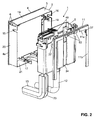
- eine räumliche schematische Ansicht der erfindungsgemässen Spülvorrichtung, wobei einzelne Teile aus technischen Gründen auseinander gezogen sind,
- Figur 2
- eine weitere schematische und räumliche Ansicht der erfindungsgemässen Spülvorrichtung, wobei auch hier einzelne Teile auseinander gezogen sind,
- Figur 3
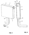
- eine räumliche Ansicht der erfindungsgemässen Spülvorrichtung,
- Figur 4
- eine Seitenansicht der erfindungsgemässen Spülvorrichtung,
- Figur 5
- ein vertikaler Schnitt durch die erfindungsgemässe Spülvorrichtung,
- Figur 6
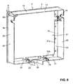
- eine räumliche Ansicht des Tragrahmens von der Rückseite her gesehen,
- Figur 7
- eine räumliche Teilansicht des Tragrahmens und
- Figur 8
- eine räumliche Ansicht der Betätigungsvorrichtung.
- Die in
Figur 1 und2 gezeigte Spülvorrichtung 1 besitzt einen Wasserkasten 5 zur Lagerung von hier nicht gezeigtem Spülwasser. Das Volumen des Spülwassers kann beispielsweise etwa 6 Liter betragen. Der Wasserkasten 5 besitzt in einem hier nicht gezeigten Boden eine Öffnung, in die ein Spülrohr 12 eingesetzt und mit einer Überwurfmutter 36 befestigt ist. Die Spülauslösung erfolgt in an sich bekannter Weise durch Betätigen der inFigur 5 gezeigten Ablaufarmatur 26 mittels einer inFigur 8 detaillierter gezeigter Betätigungsvorrichtung 7, die von oben in eine Öffnung 39 des Wasserkastens 5 eingesetzt ist. Die Ablaufarmatur 26 kann wie gezeigt mittig im Wasserkasten 5 montiert sein. Denkbar ist jedoch auch eine seitlich versetzte Anordnung, wobei entsprechend auch das Spülrohr seitlich versetzt wäre. Nach einer Spülung schliesst die Ablaufarmatur 26 selbsttätig, wonach über ein Einlaufventil 25 der Wasserkasten 5 wieder gefüllt wird. An der Aussenseite des Wasserkastens 5 ist ein Isolationsteil 10 aus Dämmelement zum Verhindern von Schwitzwasser angeordnet. Das Einlaufventil 25 ist mit einem hier nicht gezeigten Schlauch über ein Anschlussteil 9, das ein Eckventil sein kann, mit einer hier nicht gezeigten Wasserleitung verbunden. In an sich bekannterweise kann der Wasserkasten 5 an einer hier nicht gezeigten Gebäudewand befestigt werden. - Der Wasserkasten 5 ist mit einer haubenförmigen Verkleidung 2 und in der Frontansicht vorzugsweise rechteckige verdeckt. Die Verkleidung 2 ist im Wesentlichen aus einem Tragrahmen 3 und einem vorzugsweise plattenförmigen Dekorelement 4 hergestellt. Am Tragrahmen 3 sind zwei Tasten 6 gelagert, die gemäss
Figur 7 im Innern des Tragrahmens 3 jeweils einen Betätigungsteil 33 aufweisen, der an einer Frontseite 28 einer Drückerstrange 8 anlegbar ist. Gegen die rückwirkende Kraft eines Federelementes 32 (Figur 7 ) können diese Betätigungsteile 33 jeweils im wesentlichen horizontal so bewegt werden, dass die entsprechende Drückerstange 8 in ihrer Längsrichtung verschoben wird. Dadurch wird einer von zwei Betätigungshebel 27 angehoben und dadurch die Ablaufarmatur 26 zur Auslösung einer Vollspülung oder Teilspülung betätigt. Die beiden Drückerstangen 8 sind an einer Brücke 29 in einem Lagerbock 35 gelagert. Der Lagerbock 35 ist von oben in die Öffnung 39 des Wasserkastens 5 eingesetzt. Die Art der Spülauslösung ist für die Erfindung nicht grundsätzlich wesentlich. Denkbar ist auch eine Spülauslösung an einem Drücker oder auch eine berührungslose Spülauslösung. Im Fall einer Auslösung mittels einer oder zwei Tasten 6 sind diese jedoch vorzugsweise wie gezeigt am Tragrahmen 3 gelagert. - Wie insbesondere die
Figuren 2 und6 zeigen, besitzt der Tragrahmen 3 eine Deckenwandung 19, zwei Seitenwandungen 20 sowie eine Bodenwandung 21. Diese bilden wie ersichtlich einen rechteckigen Rahmen. Die Bodenwandung 21 besitzt eine Ausnehmung 30 für den Durchtritt des Spülrohrs 12. An den Wandungen 19, 20 und 21 ist ein Flansch 31 angeformt, der nach innen gerichtet ist und eine vergleichsweise grosse Ausnehmung 41 (Figur 6 ) bildet. Der Flansch 31 besitzt eine Innenseite 22, die dem Wasserkasten 5 gegenüberliegt. Zur Befestigung des Tragrahmens 3 am Wasserkasten 5 sind am Flansch 31 Klammern 16 und 17 befestigt, die jeweils zwei Federarme 18 besitzen. Diese Klammern 16 können jeweils auf ein zapfenförmiges Befestigungsteil 34 des Wasserkastens 5 aufgerastet werden. Der Tragrahmen 3 ist somit lösbar am Wasserkasten 10 befestigt. Es sind hier aber auch andere lösbare oder unlösbare Befestigungen möglich. Die Verbindung mit den Klammern 16 und 17 hat jedoch den Vorteil, dass sie von aussen nicht sichtbar sind und dass sie ohne Werkzeuge gefügt und gelöst werden können. - Die Seitenwandungen 20 besitzen jeweils eine Ausnehmung 15 für den Durchtritt des Anschlussteils 9 aufweisen. Dieses Anschlussteil 9 ist in der
Figur 1 auf der rechten Seite angeordnet, möglich ist jedoch auch eine Anordnung an der anderen linken Seite. Ein Anschluss an die Druckwasserleitung ist somit wahlweise links oder rechts möglich. Für die Lagerung der Tasten 6 besitzt gemässFigur 6 der Tragrahmen 3 an der oberen rechten Ecke eine Ausnehmung 50. Diese Ausnehmung 50 kann aber auch an einer anderen Stelle des Tragrahmens 3 angeordnet sein. - Am Tragrahmen 3 ist ein Dekorelement 4 befestigt, das gemäss
Figur 1 eine vorzugsweise ebene Frontseite 14 besitzt. Dieses Dekorelement 4 bildet die gesamte Frontseite der Verkleidung 2. Die genannten Wandungen 19, 20 und 21 bilden hier die Oberseite 51 sowie die Seitenflächen 52 als auch die hier nicht gezeigte Unterseite der Verkleidung 2. Die Wandungen 19, 20 können jedoch auch mit hier nicht gezeigten entsprechend streifenförmigen Dekorelementen verkleidet sein. Eine aussenseitige Verkleidung der Bodenwandung 21 ist in der Regel nicht erforderlich, da die entsprechende Unterseite in der Regel nicht direkt sichtbar ist. Die Wandungen 19, 20 und 21 sind somit aussen sichtbare Teile der Verkleidung. - Das Dekorelement 4 ist vorzugsweise plattenförmig ausgebildet und so dimensioniert, dass es den Tragrahmen 3 gemäss den
Figuren 2 und6 mit einem schmalen umlaufenden Rand 4a überragt. Das Dekorelement 4 kann beispielsweise aus einem Verbundmaterial, aus Glas, aus Stein oder sonst einem Material hergestellt sein. Es kann mit hier nicht gezeigten Verzierungsteilen versehen sein. Das Dekorelement 4 kann lösbar oder unlösbar mit dem Tragrahmen 3 verbunden sein. Beispielsweise kann das Dekorelement 4 am Flansch 31 angeklebt sein. Möglich ist aber auch eine Befestigung über hier nicht gezeigte Stifte, Klammern, Rastelemente und dergleichen. - Die Verkleidung 2 bildet gleichzeitig den Deckel des Wasserkastens 5. Grundsätzlich ist jedoch auch eine Ausführung denkbar, bei welcher der Wasserkasten 5 mit einem eigenen Deckel verschlossen ist. In diesem Fall kann bei der Verkleidung 2 die Deckenwandung 19 weggelassen sein.
- Am Wasserkasten 5 ist rückseitig ein U-förmiger Rahmen 11 angeordnet. Dieser besitzt einen horizontal verlaufenden Steg 11 a und nach unten gerichtete parallele gegenüberliegende Arme 11b. Am Steg 11a sind zwei Laschen 53 angeordnet, mit denen der Rahmen 11 von oben auf zwei Befestigungselemente 40 aufgeschoben werden kann. Der Steg 11 a besitzt gemäss
Figur 1 eine vergleichsweise schmale Aussenseite 38. Dies gilt ebenfalls für die nach unten ragenden Arme 11b. Der Rahmen 11 ist so ausgebildet und angeordnet, dass er im montierten Zustand mit der genannten Aussenseite 38 gemässFigur 4 eine Schattenfuge 54 bildet. Diese Schattenfuge 54 umgibt die Spülvorrichtung 1 nach der Befestigung an der oberseitig und seitlich. Die Schattenfuge 54 grenzt an die inFigur 6 gezeigte Oberseite 51 der Wandung 19 sowie an die Seitenflächen 52 der Wandungen 20. - Das Spülrohr 12 ragt wie oben erwähnt unten aus der Verkleidung 2 heraus. Auf dieses Spülrohr 2 ist eine winkelförmige Spülrohrverkleidung 13 aufgesetzt, die das Spülrohr 12 verdeckt. Damit die Spülrohrverkleidung 13 auf das Spülrohr 12 aufgesetzt werden kann, besitzt diese rückseitig eine sich vertikal erstreckende Ausnehmung 23. Im horizontalen Bereich ist dies Spülrohrverkleidung 13 so ausgebildet, dass das Spülrohr 12 auch unterseitig verdeckt ist, wie die
Figur 3 erkennen lässt. Die Spülrohrverkleidung 13 ist hier vorzugsweise ein separates Teil, das ebenfalls unterschiedlich und insbesondere aus unterschiedlichen Materialien und unterschiedlicher Oberfläche hergestellt werden kann. Insbesondere ist die Spülrohrverkleidung 13 designmässig an die Verkleidung 2 und insbesondere an das Dekorelement 4 angepasst. Die Spülrohrverkleidung 13 kann beispielsweise mit hier nicht gezeigten Rastelementen auf das Spülrohr 12 aufgerastet. -
- 1
- Spülvorrichtung
- 2
- Verkleidung
- 3
- Tragrahmen
- 4
- Dekorelement
- 4a
- Rand
- 5
- Wasserkasten
- 6
- Tasten
- 7
- Betätigungsvorrichtung
- 8
- Drückerstangen
- 9
- Anschlussteil
- 10
- Isolationsteil
- 11
- Rahmen
- 12
- Spülrohr
- 13
- Spülrohrverkleidung
- 14
- Frontseite
- 15
- Ausnehmung
- 16
- Klammer
- 17
- Klammer
- 18
- Federarm
- 19
- Deckenwandung
- 20
- Seitenwandung
- 21
- Bodenwandung
- 22
- Innenseite
- 23
- Ausnehmung
- 24
- Kragen
- 25
- Einlaufventil
- 26
- Ablaufarmatur
- 27
- Betätigungshebel
- 28
- Frontseite
- 29
- Brücke
- 30
- Ausnehmung
- 31
- Flansch
- 32
- Federlement
- 33
- Betätigungsteil
- 34
- Befestigungselement
- 35
- Lagerbock
- 36
- Überwurfmutter
- 37
- Lasche
- 38
- Aussenseite
- 39
- Öffnung
- 40
- Befestigungselement
- 41
- Ausnehmung
- 50
- Ausnehmung
- 51
- Oberseite
- 52
- Seitenfläche
- 53
- Laschen
- 54
- Schattenfuge
Claims (15)
- Spülvorrichtung für ein Wasserklosett, mit einem Wasserkasten (5) zum Lagern von Spülwasser und mit einer den Wasserkasten (5) wenigstens bereichsweise verdeckenden Verkleidung (2), dadurch gekennzeichnet, dass die Verkleidung (2) aus einem Tragrahmen (3) und wenigstens einen an diesem befestigten Dekorelement (4) hergestellt ist.
- Spülvorrichtung nach Anspruch 1, dadurch gekennzeichnet, dass das wenigstens eine Dekorelement (4) wenigstens bereichsweise eine Frontseite (14) der Verkleidung (2) bildet.
- Spülvorrichtung nach Anspruch 2, dadurch gekennzeichnet, dass das wenigstens eine Dekorelement (4) plattenförmig ausgebildet ist.
- Spülvorrichtung nach einem der Ansprüche 1 bis 3, dadurch gekennzeichnet, dass das wenigstens eine Dekorelement (4) lösbar oder unlösbar mit dem Tragrahmen (3) verbunden ist.
- Spülvorrichtung nach einem der Ansprüche 1 bis 4, dadurch gekennzeichnet, dass die Verkleidung (2) am Wasserkasten (5) gelagert ist.
- Spülvorrichtung nach Anspruch 5, dadurch gekennzeichnet, dass die Verkleidung (2) auf den Wasserkasten (5) aufgesteckt ist.
- Spülvorrichtung nach Anspruch 5 oder 6, dadurch gekennzeichnet, dass am Tragrahmen (3) innenseitig Rastelemente (16, 17) angeordnet sind, die mit Rastelementen (34) des Wasserkastens (5) verrastet sind.
- Spülvorrichtung nach einem der Ansprüche 1 bis 7, dadurch gekennzeichnet, dass am Tragrahmen (3) wenigstens ein Betätigungselement (6) zum Auslösen einer Spülung gelagert ist.
- Spülvorrichtung nach Anspruch 8, dadurch gekennzeichnet, dass das Betätigungselement (6) wenigstens eine Taste (6) aufweist.
- Spülvorrichtung nach Anspruch 8 oder 9, dadurch gekennzeichnet, dass das wenigstens eine Betätigungselement (6) in eine Ausnehmung (50) des Tragrahmens (3) eingesetzt ist.
- Spülvorrichtung nach einem der Ansprüche 1 bis 10, dadurch gekennzeichnet, dass am Wasserkasten (5) ein Eckventil (9) angeordnet ist und dass dieses Eckventil (9) mit der Verkleidung (2) abgedeckt ist.
- Spülvorrichtung nach einem der Ansprüche 1 bis 11, dadurch gekennzeichnet, dass an einer Unterseite des Wasserkastens (5) ein Spülrohr (12) angeordnet ist und dass dieses Spülrohr (12) von einer Spülrohrverkleidung (13) abgedeckt ist.
- Spülvorrichtung nach einem der Ansprüche 1 bis 12, dadurch gekennzeichnet, dass das wenigstens eine Dekorelement (4) den Tragrahmen (3) seitlich überragt.
- Spülvorrichtung nach einem der Ansprüche 1 bis 13, dadurch gekennzeichnet, dass an einer Rückseite des Tragrahmens (3) ein Rahmen (11) zum Bilden einer Schattenfuge (54) angeordnet ist.
- Spülvorrichtung nach Anspruch 14, dadurch gekennzeichnet, dass der Rahmen (11) an den Wasserkasten (5) befestigt ist.
Priority Applications (2)
| Application Number | Priority Date | Filing Date | Title |
|---|---|---|---|
| EP08405227A EP2166162B1 (de) | 2008-09-17 | 2008-09-17 | Spülvorrichtung für ein Wasserklosett |
| DK08405227T DK2166162T3 (da) | 2008-09-17 | 2008-09-17 | Skylleindretning til et vandkloset |
Applications Claiming Priority (1)
| Application Number | Priority Date | Filing Date | Title |
|---|---|---|---|
| EP08405227A EP2166162B1 (de) | 2008-09-17 | 2008-09-17 | Spülvorrichtung für ein Wasserklosett |
Publications (2)
| Publication Number | Publication Date |
|---|---|
| EP2166162A1 true EP2166162A1 (de) | 2010-03-24 |
| EP2166162B1 EP2166162B1 (de) | 2013-03-27 |
Family
ID=40297801
Family Applications (1)
| Application Number | Title | Priority Date | Filing Date |
|---|---|---|---|
| EP08405227A Not-in-force EP2166162B1 (de) | 2008-09-17 | 2008-09-17 | Spülvorrichtung für ein Wasserklosett |
Country Status (2)
| Country | Link |
|---|---|
| EP (1) | EP2166162B1 (de) |
| DK (1) | DK2166162T3 (de) |
Cited By (4)
| Publication number | Priority date | Publication date | Assignee | Title |
|---|---|---|---|---|
| ITMI20131953A1 (it) * | 2013-11-22 | 2015-05-23 | Oliveira & Irmao Sa | Cassetta di risciacquo con una copertura intercambiabile |
| EP3933129A1 (de) * | 2020-07-03 | 2022-01-05 | Geberit International AG | Sanitäres installationssystem |
| EP3933130A1 (de) * | 2020-07-03 | 2022-01-05 | Geberit International AG | Sanitäres installationssystem |
| CN116685748A (zh) * | 2020-11-26 | 2023-09-01 | 鲁文·锡安 | 用于铺设砖瓦的墙 |
Citations (6)
| Publication number | Priority date | Publication date | Assignee | Title |
|---|---|---|---|---|
| GB519423A (en) | 1938-09-14 | 1940-03-27 | Fordham Pressings Ltd | Improvements in or relating to the cisterns of syphonic flushing apparatus |
| DE1259259B (de) * | 1964-03-10 | 1968-01-18 | Karl Schwab G M B H | In die Wand eingebauter Klosettspuelkasten |
| DE2653363A1 (de) | 1976-11-24 | 1978-06-01 | Chloride Group Ltd | Wasserklosett |
| EP0615026A1 (de) | 1993-02-05 | 1994-09-14 | Malte Fierlings | Spülvorrichtung für ein Wasserklosett |
| EP1245748A2 (de) * | 2001-03-02 | 2002-10-02 | Geberit Technik Ag | Tragvorrichtung für sanitäre Einrichtungen |
| EP1854927A1 (de) | 2006-05-09 | 2007-11-14 | Geberit Technik Ag | Frontverkleidung mit Betätigungsvorrichtung für Spülkasten |
Family Cites Families (2)
| Publication number | Priority date | Publication date | Assignee | Title |
|---|---|---|---|---|
| NL7104254A (de) * | 1971-03-30 | 1972-10-03 | ||
| US5027493A (en) * | 1988-07-11 | 1991-07-02 | Gaylan Industries, Inc. | Toilet tank cover and method of installation |
-
2008
- 2008-09-17 EP EP08405227A patent/EP2166162B1/de not_active Not-in-force
- 2008-09-17 DK DK08405227T patent/DK2166162T3/da active
Patent Citations (6)
| Publication number | Priority date | Publication date | Assignee | Title |
|---|---|---|---|---|
| GB519423A (en) | 1938-09-14 | 1940-03-27 | Fordham Pressings Ltd | Improvements in or relating to the cisterns of syphonic flushing apparatus |
| DE1259259B (de) * | 1964-03-10 | 1968-01-18 | Karl Schwab G M B H | In die Wand eingebauter Klosettspuelkasten |
| DE2653363A1 (de) | 1976-11-24 | 1978-06-01 | Chloride Group Ltd | Wasserklosett |
| EP0615026A1 (de) | 1993-02-05 | 1994-09-14 | Malte Fierlings | Spülvorrichtung für ein Wasserklosett |
| EP1245748A2 (de) * | 2001-03-02 | 2002-10-02 | Geberit Technik Ag | Tragvorrichtung für sanitäre Einrichtungen |
| EP1854927A1 (de) | 2006-05-09 | 2007-11-14 | Geberit Technik Ag | Frontverkleidung mit Betätigungsvorrichtung für Spülkasten |
Cited By (5)
| Publication number | Priority date | Publication date | Assignee | Title |
|---|---|---|---|---|
| ITMI20131953A1 (it) * | 2013-11-22 | 2015-05-23 | Oliveira & Irmao Sa | Cassetta di risciacquo con una copertura intercambiabile |
| EP2876221A1 (de) | 2013-11-22 | 2015-05-27 | Oliveira & Irmao S.A. | Spülkasten mit einer austauschbaren Abdeckung |
| EP3933129A1 (de) * | 2020-07-03 | 2022-01-05 | Geberit International AG | Sanitäres installationssystem |
| EP3933130A1 (de) * | 2020-07-03 | 2022-01-05 | Geberit International AG | Sanitäres installationssystem |
| CN116685748A (zh) * | 2020-11-26 | 2023-09-01 | 鲁文·锡安 | 用于铺设砖瓦的墙 |
Also Published As
| Publication number | Publication date |
|---|---|
| EP2166162B1 (de) | 2013-03-27 |
| DK2166162T3 (da) | 2013-07-01 |
Similar Documents
| Publication | Publication Date | Title |
|---|---|---|
| EP2166163B1 (de) | Montageeinrichtung für eine WC-Schüssel | |
| EP1908887B1 (de) | Bodenablauf, insbesondere in Form einer Duschrinne | |
| EP2191215A1 (de) | Kältegerät | |
| EP2166162B1 (de) | Spülvorrichtung für ein Wasserklosett | |
| EP2360340B2 (de) | Türanlage | |
| EP2581507A1 (de) | Dusche und Profilelement hierfür | |
| EP3321430B1 (de) | Befestigung einer abdeckplatte einer revisionsöffnung | |
| EP2045404B1 (de) | Spültaste für die Betätigung einer Spülvorrichtung | |
| DE19538944C2 (de) | Installationsgerät zum Einbau in eine Wand, Säule oder dergleichen | |
| DE202016003734U1 (de) | Dekor- und/oder Funktionsteil für den Einbau in einen Eckbereich oder eine Nische, beispielsweise eines zumindest teilweise gefliesten Raumes | |
| EP1953888B1 (de) | Schalter einer Steuerung einer elektrischen Thermostatarmatur zur Betätigung der Armatur | |
| EP2464927B1 (de) | Türeinbauteil für ein kältegerät | |
| EP2690229B1 (de) | Montageeinrichtung für eine sanitäre Apparatur | |
| DE202018100338U1 (de) | Pflanzenkübelverkleidung | |
| EP1723285B1 (de) | Brauseanordnung | |
| EP1936048B1 (de) | Unterputzspülkasten mit stufenförmig ausgebildetem Kastenkörper | |
| DE102004006097B4 (de) | Möbelboden | |
| EP3257413B1 (de) | Dekor- und/oder funktionsteil für den einbau in einen eckbereich oder eine nische, beispielsweise eines zumindest teilweise gefliesten raumes | |
| DE202015001752U1 (de) | Spüleinheit | |
| EP1700960A3 (de) | Befestigungssystem für Sanitärelemente und Spülkasten | |
| EP2891755A1 (de) | Sockelleiste | |
| DE102005021563A1 (de) | Justierschiene | |
| DE10001517C1 (de) | Vorbauwand, insbesondere für Sanitärräume | |
| DE102008042944B4 (de) | Geschirrspülmaschine mit einem Frontelement | |
| AT409330B (de) | Dusche |
Legal Events
| Date | Code | Title | Description |
|---|---|---|---|
| PUAI | Public reference made under article 153(3) epc to a published international application that has entered the european phase |
Free format text: ORIGINAL CODE: 0009012 |
|
| AK | Designated contracting states |
Kind code of ref document: A1 Designated state(s): AT BE BG CH CY CZ DE DK EE ES FI FR GB GR HR HU IE IS IT LI LT LU LV MC MT NL NO PL PT RO SE SI SK TR |
|
| AX | Request for extension of the european patent |
Extension state: AL BA MK RS |
|
| 17P | Request for examination filed |
Effective date: 20100414 |
|
| 17Q | First examination report despatched |
Effective date: 20100610 |
|
| AKX | Designation fees paid |
Designated state(s): AT BE BG CH CY CZ DE DK EE ES FI FR GB GR HR HU IE IS IT LI LT LU LV MC MT NL NO PL PT RO SE SI SK TR |
|
| GRAP | Despatch of communication of intention to grant a patent |
Free format text: ORIGINAL CODE: EPIDOSNIGR1 |
|
| RIN1 | Information on inventor provided before grant (corrected) |
Inventor name: SCHERRER, JOERG |
|
| GRAS | Grant fee paid |
Free format text: ORIGINAL CODE: EPIDOSNIGR3 |
|
| GRAA | (expected) grant |
Free format text: ORIGINAL CODE: 0009210 |
|
| AK | Designated contracting states |
Kind code of ref document: B1 Designated state(s): AT BE BG CH CY CZ DE DK EE ES FI FR GB GR HR HU IE IS IT LI LT LU LV MC MT NL NO PL PT RO SE SI SK TR |
|
| REG | Reference to a national code |
Ref country code: GB Ref legal event code: FG4D Free format text: NOT ENGLISH |
|
| REG | Reference to a national code |
Ref country code: CH Ref legal event code: EP |
|
| REG | Reference to a national code |
Ref country code: AT Ref legal event code: REF Ref document number: 603508 Country of ref document: AT Kind code of ref document: T Effective date: 20130415 |
|
| REG | Reference to a national code |
Ref country code: IE Ref legal event code: FG4D Free format text: LANGUAGE OF EP DOCUMENT: GERMAN |
|
| REG | Reference to a national code |
Ref country code: CH Ref legal event code: NV Representative=s name: ISLER AND PEDRAZZINI AG, CH |
|
| REG | Reference to a national code |
Ref country code: DE Ref legal event code: R096 Ref document number: 502008009581 Country of ref document: DE Effective date: 20130529 |
|
| REG | Reference to a national code |
Ref country code: DK Ref legal event code: T3 |
|
| PG25 | Lapsed in a contracting state [announced via postgrant information from national office to epo] |
Ref country code: LT Free format text: LAPSE BECAUSE OF FAILURE TO SUBMIT A TRANSLATION OF THE DESCRIPTION OR TO PAY THE FEE WITHIN THE PRESCRIBED TIME-LIMIT Effective date: 20130327 Ref country code: SE Free format text: LAPSE BECAUSE OF FAILURE TO SUBMIT A TRANSLATION OF THE DESCRIPTION OR TO PAY THE FEE WITHIN THE PRESCRIBED TIME-LIMIT Effective date: 20130327 Ref country code: NO Free format text: LAPSE BECAUSE OF FAILURE TO SUBMIT A TRANSLATION OF THE DESCRIPTION OR TO PAY THE FEE WITHIN THE PRESCRIBED TIME-LIMIT Effective date: 20130627 Ref country code: BG Free format text: LAPSE BECAUSE OF FAILURE TO SUBMIT A TRANSLATION OF THE DESCRIPTION OR TO PAY THE FEE WITHIN THE PRESCRIBED TIME-LIMIT Effective date: 20130627 |
|
| REG | Reference to a national code |
Ref country code: NL Ref legal event code: T3 |
|
| REG | Reference to a national code |
Ref country code: LT Ref legal event code: MG4D |
|
| PG25 | Lapsed in a contracting state [announced via postgrant information from national office to epo] |
Ref country code: GR Free format text: LAPSE BECAUSE OF FAILURE TO SUBMIT A TRANSLATION OF THE DESCRIPTION OR TO PAY THE FEE WITHIN THE PRESCRIBED TIME-LIMIT Effective date: 20130628 Ref country code: LV Free format text: LAPSE BECAUSE OF FAILURE TO SUBMIT A TRANSLATION OF THE DESCRIPTION OR TO PAY THE FEE WITHIN THE PRESCRIBED TIME-LIMIT Effective date: 20130327 Ref country code: SI Free format text: LAPSE BECAUSE OF FAILURE TO SUBMIT A TRANSLATION OF THE DESCRIPTION OR TO PAY THE FEE WITHIN THE PRESCRIBED TIME-LIMIT Effective date: 20130327 Ref country code: FI Free format text: LAPSE BECAUSE OF FAILURE TO SUBMIT A TRANSLATION OF THE DESCRIPTION OR TO PAY THE FEE WITHIN THE PRESCRIBED TIME-LIMIT Effective date: 20130327 |
|
| PG25 | Lapsed in a contracting state [announced via postgrant information from national office to epo] |
Ref country code: HR Free format text: LAPSE BECAUSE OF FAILURE TO SUBMIT A TRANSLATION OF THE DESCRIPTION OR TO PAY THE FEE WITHIN THE PRESCRIBED TIME-LIMIT Effective date: 20130327 |
|
| PG25 | Lapsed in a contracting state [announced via postgrant information from national office to epo] |
Ref country code: SK Free format text: LAPSE BECAUSE OF FAILURE TO SUBMIT A TRANSLATION OF THE DESCRIPTION OR TO PAY THE FEE WITHIN THE PRESCRIBED TIME-LIMIT Effective date: 20130327 Ref country code: IS Free format text: LAPSE BECAUSE OF FAILURE TO SUBMIT A TRANSLATION OF THE DESCRIPTION OR TO PAY THE FEE WITHIN THE PRESCRIBED TIME-LIMIT Effective date: 20130727 Ref country code: RO Free format text: LAPSE BECAUSE OF FAILURE TO SUBMIT A TRANSLATION OF THE DESCRIPTION OR TO PAY THE FEE WITHIN THE PRESCRIBED TIME-LIMIT Effective date: 20130327 Ref country code: EE Free format text: LAPSE BECAUSE OF FAILURE TO SUBMIT A TRANSLATION OF THE DESCRIPTION OR TO PAY THE FEE WITHIN THE PRESCRIBED TIME-LIMIT Effective date: 20130327 Ref country code: CZ Free format text: LAPSE BECAUSE OF FAILURE TO SUBMIT A TRANSLATION OF THE DESCRIPTION OR TO PAY THE FEE WITHIN THE PRESCRIBED TIME-LIMIT Effective date: 20130327 Ref country code: PT Free format text: LAPSE BECAUSE OF FAILURE TO SUBMIT A TRANSLATION OF THE DESCRIPTION OR TO PAY THE FEE WITHIN THE PRESCRIBED TIME-LIMIT Effective date: 20130729 Ref country code: ES Free format text: LAPSE BECAUSE OF FAILURE TO SUBMIT A TRANSLATION OF THE DESCRIPTION OR TO PAY THE FEE WITHIN THE PRESCRIBED TIME-LIMIT Effective date: 20130708 |
|
| PG25 | Lapsed in a contracting state [announced via postgrant information from national office to epo] |
Ref country code: CY Free format text: LAPSE BECAUSE OF FAILURE TO SUBMIT A TRANSLATION OF THE DESCRIPTION OR TO PAY THE FEE WITHIN THE PRESCRIBED TIME-LIMIT Effective date: 20130327 Ref country code: PL Free format text: LAPSE BECAUSE OF FAILURE TO SUBMIT A TRANSLATION OF THE DESCRIPTION OR TO PAY THE FEE WITHIN THE PRESCRIBED TIME-LIMIT Effective date: 20130327 |
|
| PLBE | No opposition filed within time limit |
Free format text: ORIGINAL CODE: 0009261 |
|
| STAA | Information on the status of an ep patent application or granted ep patent |
Free format text: STATUS: NO OPPOSITION FILED WITHIN TIME LIMIT |
|
| 26N | No opposition filed |
Effective date: 20140103 |
|
| BERE | Be: lapsed |
Owner name: GEBERIT INTERNATIONAL A.G. Effective date: 20130930 |
|
| REG | Reference to a national code |
Ref country code: DE Ref legal event code: R097 Ref document number: 502008009581 Country of ref document: DE Effective date: 20140103 |
|
| PG25 | Lapsed in a contracting state [announced via postgrant information from national office to epo] |
Ref country code: MC Free format text: LAPSE BECAUSE OF FAILURE TO SUBMIT A TRANSLATION OF THE DESCRIPTION OR TO PAY THE FEE WITHIN THE PRESCRIBED TIME-LIMIT Effective date: 20130327 |
|
| REG | Reference to a national code |
Ref country code: IE Ref legal event code: MM4A |
|
| PG25 | Lapsed in a contracting state [announced via postgrant information from national office to epo] |
Ref country code: IE Free format text: LAPSE BECAUSE OF NON-PAYMENT OF DUE FEES Effective date: 20130917 Ref country code: BE Free format text: LAPSE BECAUSE OF NON-PAYMENT OF DUE FEES Effective date: 20130930 |
|
| PGFP | Annual fee paid to national office [announced via postgrant information from national office to epo] |
Ref country code: DK Payment date: 20140919 Year of fee payment: 7 Ref country code: CH Payment date: 20140916 Year of fee payment: 7 |
|
| PGFP | Annual fee paid to national office [announced via postgrant information from national office to epo] |
Ref country code: NL Payment date: 20140918 Year of fee payment: 7 |
|
| PG25 | Lapsed in a contracting state [announced via postgrant information from national office to epo] |
Ref country code: MT Free format text: LAPSE BECAUSE OF FAILURE TO SUBMIT A TRANSLATION OF THE DESCRIPTION OR TO PAY THE FEE WITHIN THE PRESCRIBED TIME-LIMIT Effective date: 20130327 Ref country code: TR Free format text: LAPSE BECAUSE OF FAILURE TO SUBMIT A TRANSLATION OF THE DESCRIPTION OR TO PAY THE FEE WITHIN THE PRESCRIBED TIME-LIMIT Effective date: 20130327 |
|
| REG | Reference to a national code |
Ref country code: DE Ref legal event code: R082 Ref document number: 502008009581 Country of ref document: DE Representative=s name: HOEGER, STELLRECHT & PARTNER PATENTANWAELTE MB, DE |
|
| PG25 | Lapsed in a contracting state [announced via postgrant information from national office to epo] |
Ref country code: LU Free format text: LAPSE BECAUSE OF NON-PAYMENT OF DUE FEES Effective date: 20130917 Ref country code: HU Free format text: LAPSE BECAUSE OF FAILURE TO SUBMIT A TRANSLATION OF THE DESCRIPTION OR TO PAY THE FEE WITHIN THE PRESCRIBED TIME-LIMIT; INVALID AB INITIO Effective date: 20080917 |
|
| REG | Reference to a national code |
Ref country code: FR Ref legal event code: PLFP Year of fee payment: 8 |
|
| PGFP | Annual fee paid to national office [announced via postgrant information from national office to epo] |
Ref country code: GB Payment date: 20150917 Year of fee payment: 8 |
|
| PGFP | Annual fee paid to national office [announced via postgrant information from national office to epo] |
Ref country code: FR Payment date: 20150922 Year of fee payment: 8 Ref country code: AT Payment date: 20150921 Year of fee payment: 8 |
|
| REG | Reference to a national code |
Ref country code: DK Ref legal event code: EBP Effective date: 20150930 |
|
| REG | Reference to a national code |
Ref country code: CH Ref legal event code: PL |
|
| REG | Reference to a national code |
Ref country code: NL Ref legal event code: MM Effective date: 20151001 |
|
| PG25 | Lapsed in a contracting state [announced via postgrant information from national office to epo] |
Ref country code: CH Free format text: LAPSE BECAUSE OF NON-PAYMENT OF DUE FEES Effective date: 20150930 Ref country code: LI Free format text: LAPSE BECAUSE OF NON-PAYMENT OF DUE FEES Effective date: 20150930 |
|
| PG25 | Lapsed in a contracting state [announced via postgrant information from national office to epo] |
Ref country code: NL Free format text: LAPSE BECAUSE OF NON-PAYMENT OF DUE FEES Effective date: 20151001 |
|
| PG25 | Lapsed in a contracting state [announced via postgrant information from national office to epo] |
Ref country code: DK Free format text: LAPSE BECAUSE OF NON-PAYMENT OF DUE FEES Effective date: 20150930 |
|
| REG | Reference to a national code |
Ref country code: AT Ref legal event code: MM01 Ref document number: 603508 Country of ref document: AT Kind code of ref document: T Effective date: 20160917 |
|
| GBPC | Gb: european patent ceased through non-payment of renewal fee |
Effective date: 20160917 |
|
| REG | Reference to a national code |
Ref country code: FR Ref legal event code: ST Effective date: 20170531 |
|
| PG25 | Lapsed in a contracting state [announced via postgrant information from national office to epo] |
Ref country code: FR Free format text: LAPSE BECAUSE OF NON-PAYMENT OF DUE FEES Effective date: 20160930 Ref country code: GB Free format text: LAPSE BECAUSE OF NON-PAYMENT OF DUE FEES Effective date: 20160917 |
|
| PG25 | Lapsed in a contracting state [announced via postgrant information from national office to epo] |
Ref country code: AT Free format text: LAPSE BECAUSE OF NON-PAYMENT OF DUE FEES Effective date: 20160917 |
|
| REG | Reference to a national code |
Ref country code: DE Ref legal event code: R082 Ref document number: 502008009581 Country of ref document: DE Representative=s name: HOEGER, STELLRECHT & PARTNER PATENTANWAELTE MB, DE |
|
| P01 | Opt-out of the competence of the unified patent court (upc) registered |
Effective date: 20230516 |
|
| PGFP | Annual fee paid to national office [announced via postgrant information from national office to epo] |
Ref country code: IT Payment date: 20230921 Year of fee payment: 16 |
|
| PGFP | Annual fee paid to national office [announced via postgrant information from national office to epo] |
Ref country code: DE Payment date: 20230920 Year of fee payment: 16 |
|
| REG | Reference to a national code |
Ref country code: DE Ref legal event code: R119 Ref document number: 502008009581 Country of ref document: DE |
|
| PG25 | Lapsed in a contracting state [announced via postgrant information from national office to epo] |
Ref country code: DE Free format text: LAPSE BECAUSE OF NON-PAYMENT OF DUE FEES Effective date: 20250401 |
|
| PG25 | Lapsed in a contracting state [announced via postgrant information from national office to epo] |
Ref country code: IT Free format text: LAPSE BECAUSE OF NON-PAYMENT OF DUE FEES Effective date: 20240917 |