EP2165902A1 - Système de freinage électropneumatique de véhicule ferroviaire et véhicule ferroviaire équipé d'un tel système - Google Patents
Système de freinage électropneumatique de véhicule ferroviaire et véhicule ferroviaire équipé d'un tel système Download PDFInfo
- Publication number
- EP2165902A1 EP2165902A1 EP08290892A EP08290892A EP2165902A1 EP 2165902 A1 EP2165902 A1 EP 2165902A1 EP 08290892 A EP08290892 A EP 08290892A EP 08290892 A EP08290892 A EP 08290892A EP 2165902 A1 EP2165902 A1 EP 2165902A1
- Authority
- EP
- European Patent Office
- Prior art keywords
- brake
- pipe
- rail vehicle
- air
- rescue
- Prior art date
- Legal status (The legal status is an assumption and is not a legal conclusion. Google has not performed a legal analysis and makes no representation as to the accuracy of the status listed.)
- Granted
Links
Images


Classifications
-
- B—PERFORMING OPERATIONS; TRANSPORTING
- B60—VEHICLES IN GENERAL
- B60T—VEHICLE BRAKE CONTROL SYSTEMS OR PARTS THEREOF; BRAKE CONTROL SYSTEMS OR PARTS THEREOF, IN GENERAL; ARRANGEMENT OF BRAKING ELEMENTS ON VEHICLES IN GENERAL; PORTABLE DEVICES FOR PREVENTING UNWANTED MOVEMENT OF VEHICLES; VEHICLE MODIFICATIONS TO FACILITATE COOLING OF BRAKES
- B60T13/00—Transmitting braking action from initiating means to ultimate brake actuator with power assistance or drive; Brake systems incorporating such transmitting means, e.g. air-pressure brake systems
- B60T13/10—Transmitting braking action from initiating means to ultimate brake actuator with power assistance or drive; Brake systems incorporating such transmitting means, e.g. air-pressure brake systems with fluid assistance, drive, or release
- B60T13/66—Electrical control in fluid-pressure brake systems
- B60T13/665—Electrical control in fluid-pressure brake systems the systems being specially adapted for transferring two or more command signals, e.g. railway systems
-
- B—PERFORMING OPERATIONS; TRANSPORTING
- B60—VEHICLES IN GENERAL
- B60T—VEHICLE BRAKE CONTROL SYSTEMS OR PARTS THEREOF; BRAKE CONTROL SYSTEMS OR PARTS THEREOF, IN GENERAL; ARRANGEMENT OF BRAKING ELEMENTS ON VEHICLES IN GENERAL; PORTABLE DEVICES FOR PREVENTING UNWANTED MOVEMENT OF VEHICLES; VEHICLE MODIFICATIONS TO FACILITATE COOLING OF BRAKES
- B60T17/00—Component parts, details, or accessories of power brake systems not covered by groups B60T8/00, B60T13/00 or B60T15/00, or presenting other characteristic features
- B60T17/18—Safety devices; Monitoring
- B60T17/22—Devices for monitoring or checking brake systems; Signal devices
- B60T17/228—Devices for monitoring or checking brake systems; Signal devices for railway vehicles
Definitions
- the invention relates to a rail vehicle equipped with an electro-pneumatic brake system. It relates more particularly to the recovery of a failed rail vehicle equipped with an electro-pneumatic brake system.
- Modern railway vehicles are equipped with electronically controlled electro-pneumatic brake systems. It is mandatory that these systems are fail safe to the same level of safety as provided by a traditional UIC two-pipe air brake system.
- the electro-pneumatic brake control is configured on an "energise to release" basis. This means that an electro-pneumatic valve is energised by a safety wire that runs throughout the train consist in order to release the emergency brake. If this circuit is broken for any reason all the electro-pneumatic valves that were energised become de-energised and cause the emergency valves to make a brake application.
- the energy source used to apply brake force is in the form of compressed air.
- This compressed air is distributed from an air supply module somewhere on the train consist, to all the cars via a main reservoir pipe. On each car compressed air is taken from the main reservoir pipe into a brake supply reservoir via a non-return valve.
- This brake supply reservoir located in one car constitutes a protected brake energy supply, which is used to supply air to the friction brakes on the car, when demanded by the control system, irrespective of the condition of the main reservoir pipe.
- Both the main reservoir pipe pressure and the pressure in the brake supply reservoir are monitored by pressure switches. The pressure switches have electrical contacts that will cause the emergency brake wire to be de-energised should the air pressure in either system fall below pre-defined limits.
- the dead rail vehicle In case of system failure and automatic application of the brakes, the dead rail vehicle needs to be rescued by another rail vehicle equipped with a pneumatic air supply.
- the operations for connecting the rescuing vehicle with the dead vehicle and for releasing the air brakes and spring-applied parking brakes on the failed rail vehicle are complex and time consuming.
- the crew may need to operate isolating cocks on every vehicle to release the failsafe application of emergency brakes. If the failure is due to a low main reservoir pipe pressure caused by a major leak the crew will also need to mechanically release all the spring-applied parking brakes.
- the crew may also have to operate the brake cylinder isolating cocks on every car and spring-applied parking brake release mechanism on every spring-applied parking brake actuator.
- a rail vehicle pneumatic brake system comprising:
- the rescue pipe In case of failure of the electro-pneumatic brake control valve means or of any device in the electrical control system causing the air brake to be applied the rescue pipe will be connected to a pressure source, e.g. the brake pipe (if fitted) or main reservoir pipe of the rescuing rail vehicle. Thanks to the rescue pipe and air brake release valve means, only one single connection is required between the failed rail vehicle and the rescuing train or locomotive to bypass the electro-pneumatic brake control valve means and provide remote release of the air brakes of the failed vehicle. The proposed system allows the air brakes on the failed train to be released without the need to make any isolation and without any electrical connection.
- a pressure source e.g. the brake pipe (if fitted) or main reservoir pipe of the rescuing rail vehicle.
- the air brake release valve means is composed of one or more pneumatically operated valves, at least one of which will be preferably operated by the rescue pipe pressure.
- a fully pneumatic system is provided, which does not require any wiring between the failed rail vehicle and the rescuing vehicle.
- the air brake release valve means can comprise a five-port two-position valve, which provides a compact system.
- the air brake release valve means may comprise a three-port two-position valve and a two-port two-position valve.
- the three-port two-position valve is a pneumatically operated spring returned normally open valve.
- the two-port two-position valve is a normally closed pneumatically operated spring returned valve connected to the air brake cylinder.
- the one or more pneumatically operated valves included in the air brake release valve means may be housed in a common body.
- the rail vehicle pneumatic brake system further comprises:
- the same rescue pipe is used for automatically and remotely releasing the air brake actuators and spring-applied parking brake actuators.
- the parking brake release valve means can be composed of one or more pneumatically operated valves, at least one of which is preferably operated by the rescue pipe pressure.
- the spring-applied parking brake actuator may be connected to the main pipe either directly or via a parking brake control valve and is normally released by the main pipe pressure.
- the pressure required to fully release the spring applied parking brake is directly proportional to the force required to compress the installed spring. As release air pressure rises the parking brake force is gradually reduced until the spring force is completely counteracted by the force created by the release air pressure. Thus, the parking brake will be partially applied whenever the release pressure is less than the pressure that is required to fully release the parking brake.
- the level of application is inversely proportional to the release pressure, i.e. no pressure corresponds to full spring parking brake force, while full release pressure corresponds to no parking brake force.
- the rescue pipe is connected to the rescuing vehicles brake pipe and fluctuation in the rescue pipe pressure due to normal air brake control in the rescuing vehicle will cause partial re-application of the spring applied parking brakes on the dead vehicle being rescued whenever the rescuing vehicle applies its own brakes. If the rescuing vehicle applies emergency brakes the brake pipe pressure (and hence the rescue pipe pressure) falls to zero and the spring parking brakes of the dead train are fully re-applied.
- the spring-applied parking brake release valve means can comprise an additional valve which will isolate the spring-applied parking brake cylinder from pressure fluctuations in the rescue pipe when the pressure in the rescue pipe is within the range of normal air brake application.
- a slight drop in the rescue pipe pressure will not result in partial application of the spring-applied parking brakes.
- This makes it possible to feed the rescue pipe with a fluctuating pressure, e.g. from a brake pipe of a locomotive, which varies to control the brakes of the rescuing train.
- the pressure in the rescue pipe falls below the normal air brake range towards the emergency brake pipe pressure (zero) then the spring applied parking brakes will be fully re-applied
- the parking brake release valve means can include a shuttle valve (OR Valve) inserted between the main pipe, the rescue pipe and the parking brake cylinder in a way that will allow the spring-applied parking brake to be released if pressure is available in normal main pipe or in case of failure of the main pipe if an air supply from the rescue pipe is available.
- a shuttle valve OR Valve
- the parking brake release valve means and air brake release valve means may be assembled into a common housing, which facilitates retrofitting.
- the rail vehicle pneumatic brake system further comprises a connector for connecting the rescue pipe to a rescue hose.
- the rescue hose will be connected to a pressure source on the rescuing rail vehicle, e.g. the brake pipe of a locomotive or main brake pipe of a coach.
- the rescue pipe will not normally contain any compressed air, and for safety considerations will not be connected to any other pipework that normally contains compressed air. In this way there are no fault conditions that could cause unwanted brake release.
- the rail vehicle pneumatic brake further comprises an emergency cock for venting the rescue pipe.
- Actuating the emergency cock will result in re-establishing the connection between the brake supply reservoir and the electro-pneumatic control valve means.
- the air brakes will automatically be re-applied if the electro-pneumatic control valve means are still de-energised and pressure is still available in the brake supply reservoir.
- the spring-applied parking brake will automatically be applied.
- a rail vehicle comprising a pneumatic brake system as described hereinbefore.
- the emergency cock may preferably be located within the a car body of the rail vehicle to allow actuation by the crew during rescue.
- the rail vehicle may comprise a plurality of carriages, each carriage being provided with a pneumatic brake system as claimed in any one of the preceding claims, the rail vehicle further comprising hoses for connecting the rescue pipes and building a continuous rescue supply line.
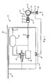
- the pneumatic brake system 10 of a rail vehicle includes a main reservoir pipe 12 for supplying a main pipe pressure to a brake supply reservoir 14 through a check valve 16, and one or more air brake actuators 18 connected to the brake supply reservoir 14 via electro-pneumatic control valve means 20, which may include one or more electro-pneumatic valves.
- electro-pneumatic control valve means 20 which may include one or more electro-pneumatic valves.
- the brake system can be used to brake more than one wheel, in which case the electro-pneumatic valve will be connected to a plurality of air brake actuators 18.
- the air brake actuator 18 combines an air cylinder 22 and a mechanism 24 linked to a friction brake 23.
- the mechanism 24 moves from a released position to an engaged position to engage the friction brake 23 upon application of an air or emergency brake pressure to the air brake cylinder and is biased towards the released position by a return spring 26.
- the electro-pneumatic control valve means 20 are connected between the brake supply reservoir 14 and the air brake cylinder 22.
- the electro-pneumatic control valve means 20 cause the air brake cylinder 22 to be connected to the brake supply reservoir 14 when de-energised and cause the air brake cylinder 22 to be vented when energised.
- An isolating cock 28 is normally installed in the pipe to the air brake cylinders.
- the pneumatic brake system also includes one or more spring-applied parking brake actuators 30.
- Each spring-applied parking brake actuator 30 is provided with a release cylinder 32 and a mechanism 34 linked to a friction brake 35.
- the mechanism 34 moves from an engaged position to a released position upon application of a compressed air pressure and is spring-biased towards the engaged position by a biasing spring 36.
- the spring-applied parking brake actuators are connected to the main reservoir pipe or the rescue pipe via a spring-applied parking brake release valve 38, which will be described hereinafter.
- the pneumatic system is also provided with a rescue pipe 40 and a five-port, two-position air brake release valve 42 controlled by the rescue pipe pressure.
- the air brake release valve 42 has one port connected to the brake supply reservoir 14, one port connected to an inlet port of the electro-pneumatic control valve means 20 and one port connected to the air brake cylinder 22 and the two remaining ports are connected to venting means.
- the port connected to the air brake cylinder 22 is closed while the brake supply reservoir 14 is connected to the electro-pneumatic control valve means 20 via the respective open ports of the air brake release valve 42.
- the air brake release valve 42 is moved to an active position to block the feed from brake supply reservoir 14 to the electro-pneumatic control valve means 20, vent the air brake cylinder 22 and any air pressure in the electro-pneumatic control valve.
- the spring-applied parking brake release valve 38 is a shuttle valve with one inlet port connected to the main reservoir pipe 12, the other inlet port connected to the rescue pipe 40 and its outlet port connected to the spring-applied parking brake cylinder 32.
- This shuttle valve 38 connects the main reservoir pipe to the spring-applied parking brake cylinder 32 and releases the spring-applied parking brake 30 when pressure is available in the main reservoir pipe 12 or in the rescue pipe 40. It allows the pressure to be released from the spring-applied parking brake cylinder 32 when no pressure is available on both the main reservoir pipe 12 and the rescue pipe 40.
- the rescue pipe, air brake release valve 42 and shuttle valve 38 form together a pneumatic remote brake release system 100 which is connected into the normal electro-pneumatic brake system 10.
- this remote brake release system 100 is connected to the main reservoir pipe 12 which extends along the length of the rail car 50, and is connected to the next cars via connectors 54 and connection hoses 56.
- the rescue pipe 40 runs along the length of the rail car 50, below the car body 52, and is provided with connectors 60 and connecting hoses 62 for connecting it to a rescuing rail vehicle and/or to the next cars.
- the rescue pipe 40 can be provided with an emergency venting valve 64, which will preferably be located close to the emergency valve 58 of the main reservoir pipe 12.
- the rescue pipes 40 of adjacent cars can thus be connected together to build a continuous rescue supply line.
- the rescue pipe 40 is not connected to any other pipework that normally contains compressed air. In this way there are no fault conditions that could cause unwanted brake release.
- the rescue pipe 40 remains depressurised.
- both the air brake release valve 42 and the spring-applied parking brake release valve 38 are inactive.
- the electro-pneumatic control valve means 20 are therefore connected to the brake supply reservoir while the spring-applied parking brake 30 is controlled by the main reservoir pipe pressure.
- a rescuing rail vehicle which can be a locomotive or a train, will be coupled to the failed train and a pneumatic pipe of the rescuing vehicle, e.g. the brake pipe of a locomotive or main reservoir pipe of a coach, will be connected to the rescue pipe 40.
- the air brake release valve 42 When the pressure rises in the rescue pipe 40, the air brake release valve 42 is actuated so as to isolate the brake supply reservoir 14 and vent the air brake cylinder 22 and the electro-pneumatic valve means 20. This loss of pressure in the air brake cylinder 22 leads to the release of the air brake 18. Simultaneously, the rescue pipe pressure opens the shuttle valve 38 and releases the spring-applied parking brake 30. The failed railed vehicle can then be towed by the rescuing rail vehicle.
- the single five-port two-position air brake release valve of the first embodiment has been replaced with two valves 421, 422 controlled by the rescue pipe pressure, one of which is dedicated to the isolation of the brake supply reservoir and the venting of the electro-pneumatic brake control valve means 20, while the other is able to vent the air brake cylinder.
- the two valves 421, 422 may be housed together with the spring-applied parking brake release valve 38 in a common valve body 60 to form a single remote brake release valve means.
- the single five-port two-position air brake release valve of the first embodiment can be housed together with the shuttle valve 38 or the check valve 382 in a common housing.
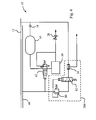
- the embodiment of figure 4 is identical to the embodiment of figure 1 , except for the addition of a charging valve 80 and a pilot valve 82 in series in the line between the rescue pipe 40 and the shuttle valve 38.
- a charging valve 80 and a pilot valve 82 in series in the line between the rescue pipe 40 and the shuttle valve 38.
- a first threshold e.g. 2 bar
- the pilot operated three-port two-position valve 82 will be operated thus connecting the charging valve 80 to the spring-applied parking brake release valve 38.
- rescue pipe pressure builds up to a second threshold (e.g. 4.8 bar) the charging valve 80 will open and allow rescue pipe pressure through the now open pilot 3/2 valve 82 to the spring applied parking brake release valve 38. This air pressure will cause the spring applied parking brake to be released.
- the charging valve 80 will close thus maintaining the spring applied parking brake release pressure at the second threshold pressure and preventing a partial application of the spring applied parking brakes.
- the pilot operated 3/2 valve 82 will revert to the spring returned position causing the spring-applied parking brake pressure to be vented and thus the spring applied parking brake will be re-applied.
- the rescue pipe can therefore be connected to a pressure source providing a variable pressure, such as a brake pipe of a rescuing locomotive.
- the charging valve 80, pilot valve 82 and check valve 38 constitute together remote spring-applied parking brake release valve means 380 which can be housed in a common valve body.
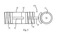
- the brakes 23, 35 constitute friction brake means applied to the same wheel 21.
- one friction brake 135 can be used as friction brake means instead of the two brakes illustrated in the previous embodiments.
- the piston or mechanism 34 of the spring-applied actuator 32 is linked to the brake pads via the piston or mechanism 24 of the air-applied actuator 24, provided the spring 26 of the air-applied actuator is significantly weaker than the spring 36 of the spring-applied actuator. If no pressure is present in the cylinder of the spring-applied actuator 32 the powerful spring 36 of the spring-applied parking brake actuator 32 moves the pistons 34, 24 and engage the brake 135 irrespective of the condition of the air-applied brake actuator.
- the air-applied brake actuator becomes active to control the position of the brake only when the cylinder of the spring-actuator is pressurized.
Landscapes
- Engineering & Computer Science (AREA)
- Transportation (AREA)
- Mechanical Engineering (AREA)
- Braking Systems And Boosters (AREA)
- Valves And Accessory Devices For Braking Systems (AREA)
Priority Applications (2)
| Application Number | Priority Date | Filing Date | Title |
|---|---|---|---|
| AT08290892T ATE523397T1 (de) | 2008-09-22 | 2008-09-22 | Schienenfahrzeug-elektropneumatikbremssystem und schienenfahrzeug mit diesem system |
| EP08290892A EP2165902B1 (fr) | 2008-09-22 | 2008-09-22 | Système de freinage électropneumatique de véhicule ferroviaire et véhicule ferroviaire équipé d'un tel système |
Applications Claiming Priority (1)
| Application Number | Priority Date | Filing Date | Title |
|---|---|---|---|
| EP08290892A EP2165902B1 (fr) | 2008-09-22 | 2008-09-22 | Système de freinage électropneumatique de véhicule ferroviaire et véhicule ferroviaire équipé d'un tel système |
Publications (2)
| Publication Number | Publication Date |
|---|---|
| EP2165902A1 true EP2165902A1 (fr) | 2010-03-24 |
| EP2165902B1 EP2165902B1 (fr) | 2011-09-07 |
Family
ID=40361705
Family Applications (1)
| Application Number | Title | Priority Date | Filing Date |
|---|---|---|---|
| EP08290892A Not-in-force EP2165902B1 (fr) | 2008-09-22 | 2008-09-22 | Système de freinage électropneumatique de véhicule ferroviaire et véhicule ferroviaire équipé d'un tel système |
Country Status (2)
| Country | Link |
|---|---|
| EP (1) | EP2165902B1 (fr) |
| AT (1) | ATE523397T1 (fr) |
Cited By (9)
| Publication number | Priority date | Publication date | Assignee | Title |
|---|---|---|---|---|
| WO2014079490A1 (fr) * | 2012-11-21 | 2014-05-30 | Bombardier Transportation Gmbh | Procédé pour action de freinage d'un essieu de frein d'un véhicule ferroviaire et système de freinage pour véhicule ferroviaire |
| CN105059313A (zh) * | 2015-07-15 | 2015-11-18 | 南车南京浦镇车辆有限公司 | 一种列车联挂救援常用制动一键缓解装置 |
| US20160082939A1 (en) * | 2012-06-07 | 2016-03-24 | Faiveley Transport Australia Ltd | Park brake control assembly |
| DE102016205125A1 (de) * | 2016-03-29 | 2017-10-05 | Siemens Aktiengesellschaft | Bremssystem, Schienenfahrzeug mit einem Bremssystem sowie Verfahren zum Betrieb eines Bremssystems |
| CN108454649A (zh) * | 2018-04-04 | 2018-08-28 | 湖南高速铁路职业技术学院 | 机车与动车组停放制动远程缓解系统 |
| CN109318880A (zh) * | 2017-12-13 | 2019-02-12 | 中车长春轨道客车股份有限公司 | 一种列车制动缓解系统及列车 |
| EP3325320B1 (fr) | 2015-07-22 | 2019-04-24 | Faiveley Transport Italia S.r.l. | Système de freinage pneumatique pour véhicule de chemin de fer avec électrovanne de desserrage de frein |
| CN112776788A (zh) * | 2021-03-17 | 2021-05-11 | 中车株洲电力机车有限公司 | 机车及其制动机制动缸故障检测与冗余控制系统、方法 |
| EP3943361A4 (fr) * | 2019-07-05 | 2022-05-11 | Crrc Qingdao Sifang Rolling Stock Research Institute Co., Ltd. | Module de commande de frein de stationnement et véhicule ferroviaire |
Families Citing this family (2)
| Publication number | Priority date | Publication date | Assignee | Title |
|---|---|---|---|---|
| CA3015655C (fr) | 2016-03-03 | 2022-07-19 | Westinghouse Air Brake Technologies Corporation | Commande de frein de stationnement |
| CN112810658B (zh) * | 2021-01-12 | 2023-02-17 | 中车青岛四方机车车辆股份有限公司 | 轨道车辆的控制方法、装置、处理器和轨道车辆 |
Citations (2)
| Publication number | Priority date | Publication date | Assignee | Title |
|---|---|---|---|---|
| GB219762A (en) * | 1923-05-10 | 1924-08-07 | English Electric Co Ltd | Improvements in vehicles for use on rail traction systems |
| US3799623A (en) * | 1970-10-26 | 1974-03-26 | Westinghouse Brake & Signal | Controlling railway vehicle brakes |
-
2008
- 2008-09-22 AT AT08290892T patent/ATE523397T1/de not_active IP Right Cessation
- 2008-09-22 EP EP08290892A patent/EP2165902B1/fr not_active Not-in-force
Patent Citations (2)
| Publication number | Priority date | Publication date | Assignee | Title |
|---|---|---|---|---|
| GB219762A (en) * | 1923-05-10 | 1924-08-07 | English Electric Co Ltd | Improvements in vehicles for use on rail traction systems |
| US3799623A (en) * | 1970-10-26 | 1974-03-26 | Westinghouse Brake & Signal | Controlling railway vehicle brakes |
Cited By (19)
| Publication number | Priority date | Publication date | Assignee | Title |
|---|---|---|---|---|
| US20160082939A1 (en) * | 2012-06-07 | 2016-03-24 | Faiveley Transport Australia Ltd | Park brake control assembly |
| WO2014079490A1 (fr) * | 2012-11-21 | 2014-05-30 | Bombardier Transportation Gmbh | Procédé pour action de freinage d'un essieu de frein d'un véhicule ferroviaire et système de freinage pour véhicule ferroviaire |
| CN104936815A (zh) * | 2012-11-21 | 2015-09-23 | 庞巴迪运输有限公司 | 用于轨道交通工具轮轴的制动操作方法和用于轨道交通工具的制动系统 |
| EP2922724A1 (fr) * | 2012-11-21 | 2015-09-30 | Bombardier Transportation GmbH | Procédé pour action de freinage d'un essieu de frein d'un véhicule ferroviaire et système de freinage pour véhicule ferroviaire |
| CN104936815B (zh) * | 2012-11-21 | 2017-08-11 | 庞巴迪运输有限公司 | 用于轨道交通工具轮轴的制动操作方法和用于轨道交通工具的制动系统 |
| CN105059313A (zh) * | 2015-07-15 | 2015-11-18 | 南车南京浦镇车辆有限公司 | 一种列车联挂救援常用制动一键缓解装置 |
| EP3325320B1 (fr) | 2015-07-22 | 2019-04-24 | Faiveley Transport Italia S.r.l. | Système de freinage pneumatique pour véhicule de chemin de fer avec électrovanne de desserrage de frein |
| CN109219543A (zh) * | 2016-03-29 | 2019-01-15 | 西门子移动有限公司 | 制动系统、具有制动系统的轨道交通运输工具以及运行制动系统的方法 |
| DE102016205125A1 (de) * | 2016-03-29 | 2017-10-05 | Siemens Aktiengesellschaft | Bremssystem, Schienenfahrzeug mit einem Bremssystem sowie Verfahren zum Betrieb eines Bremssystems |
| RU2697319C1 (ru) * | 2016-03-29 | 2019-08-13 | Сименс Мобилити Гмбх | Тормозная система, рельсовое транспортное средство с тормозной системой, а также способ эксплуатации тормозной системы |
| RU2697319C9 (ru) * | 2016-03-29 | 2019-10-01 | Сименс Мобилити Гмбх | Тормозная система, рельсовое транспортное средство с тормозной системой, а также способ эксплуатации тормозной системы |
| CN109318880A (zh) * | 2017-12-13 | 2019-02-12 | 中车长春轨道客车股份有限公司 | 一种列车制动缓解系统及列车 |
| EP3636511A4 (fr) * | 2017-12-13 | 2020-08-19 | CRRC Changchun Railway Vehicles Co., Ltd. | Système de libération de frein de train et train |
| CN109318880B (zh) * | 2017-12-13 | 2021-08-06 | 中车长春轨道客车股份有限公司 | 一种列车制动缓解系统及列车 |
| CN108454649A (zh) * | 2018-04-04 | 2018-08-28 | 湖南高速铁路职业技术学院 | 机车与动车组停放制动远程缓解系统 |
| CN108454649B (zh) * | 2018-04-04 | 2023-08-15 | 湖南高速铁路职业技术学院 | 机车与动车组停放制动远程缓解系统 |
| EP3943361A4 (fr) * | 2019-07-05 | 2022-05-11 | Crrc Qingdao Sifang Rolling Stock Research Institute Co., Ltd. | Module de commande de frein de stationnement et véhicule ferroviaire |
| CN112776788A (zh) * | 2021-03-17 | 2021-05-11 | 中车株洲电力机车有限公司 | 机车及其制动机制动缸故障检测与冗余控制系统、方法 |
| CN112776788B (zh) * | 2021-03-17 | 2021-11-16 | 中车株洲电力机车有限公司 | 机车及其制动机制动缸故障检测与冗余控制系统、方法 |
Also Published As
| Publication number | Publication date |
|---|---|
| ATE523397T1 (de) | 2011-09-15 |
| EP2165902B1 (fr) | 2011-09-07 |
Similar Documents
| Publication | Publication Date | Title |
|---|---|---|
| EP2165902B1 (fr) | Système de freinage électropneumatique de véhicule ferroviaire et véhicule ferroviaire équipé d'un tel système | |
| AU2013205185B2 (en) | Park Brake Control Assembly | |
| CN110667638B (zh) | 空气制动控制单元、制动控制系统及制动控制方法 | |
| CN105015530B (zh) | 用于车辆的电驻车制动器 | |
| JP2753457B2 (ja) | 鉄道車両の空気/電空ブレーキ制御装置 | |
| CN112041209B (zh) | 用于轨道车辆的弹簧储能式制动器的紧急释放装置 | |
| US6375277B1 (en) | Manual release valve apparatus for ECP brake equipment | |
| CA2174910C (fr) | Appareil de commande de charge pour systeme de freinage electropneumatique a microprocesseur | |
| CN102267449A (zh) | 用于轨道车辆的电气动的牵引模块 | |
| US5746484A (en) | E/P interface with pneumatic control valve for back-up brake arrangement | |
| CN109353369A (zh) | 一种轨道车辆救援制动系统及控制方法 | |
| CN106660536A (zh) | 车辆的具有集成的紧急气源压力容器的压缩空气装置 | |
| EP1789296A1 (fr) | Systeme de freinage de remorque | |
| US5730504A (en) | Release assuring arrangement for combined electro-pneumatic/automatic pneumatic brake | |
| US5429424A (en) | Pneumatic brake for railway locomotives and motor cars | |
| RU46983U1 (ru) | Исполнительная часть пневматической тормозной системы пассажирского локомотива | |
| CN113401162A (zh) | 一种用于列车救援的制动系统 | |
| CN114572174B (zh) | 用于轨道车的制动控制系统 | |
| US9725080B1 (en) | Parking brake system for locomotive | |
| RU2352482C1 (ru) | Комплекс тормозного оборудования локомотива | |
| RU140138U1 (ru) | Модуль тормозного оборудования локомотива | |
| RU2794305C1 (ru) | Блок пневматической схемы шунтирования вентиля тормоза безопасности | |
| CN113928291A (zh) | 一种半动力轨道车辆动轴制动互锁控制装置及控制方法 | |
| CN113508063A (zh) | 具有行车制动器指示装置的铁路车辆制动系统以及配有这种系统的铁路车辆 | |
| OA17227A (en) | Park brake control assembly. |
Legal Events
| Date | Code | Title | Description |
|---|---|---|---|
| PUAI | Public reference made under article 153(3) epc to a published international application that has entered the european phase |
Free format text: ORIGINAL CODE: 0009012 |
|
| AK | Designated contracting states |
Kind code of ref document: A1 Designated state(s): AT BE BG CH CY CZ DE DK EE ES FI FR GB GR HR HU IE IS IT LI LT LU LV MC MT NL NO PL PT RO SE SI SK TR |
|
| AX | Request for extension of the european patent |
Extension state: AL BA MK RS |
|
| 17P | Request for examination filed |
Effective date: 20100802 |
|
| AKX | Designation fees paid |
Designated state(s): AT BE BG CH CY CZ DE DK EE ES FI FR GB GR HR HU IE IS IT LI LT LU LV MC MT NL NO PL PT RO SE SI SK TR |
|
| GRAP | Despatch of communication of intention to grant a patent |
Free format text: ORIGINAL CODE: EPIDOSNIGR1 |
|
| GRAS | Grant fee paid |
Free format text: ORIGINAL CODE: EPIDOSNIGR3 |
|
| GRAA | (expected) grant |
Free format text: ORIGINAL CODE: 0009210 |
|
| REG | Reference to a national code |
Ref country code: GB Ref legal event code: FG4D |
|
| REG | Reference to a national code |
Ref country code: CH Ref legal event code: EP |
|
| REG | Reference to a national code |
Ref country code: IE Ref legal event code: FG4D |
|
| REG | Reference to a national code |
Ref country code: DE Ref legal event code: R096 Ref document number: 602008009530 Country of ref document: DE Effective date: 20111201 |
|
| REG | Reference to a national code |
Ref country code: SE Ref legal event code: TRGR |
|
| REG | Reference to a national code |
Ref country code: NL Ref legal event code: VDEP Effective date: 20110907 |
|
| PG25 | Lapsed in a contracting state [announced via postgrant information from national office to epo] |
Ref country code: LT Free format text: LAPSE BECAUSE OF FAILURE TO SUBMIT A TRANSLATION OF THE DESCRIPTION OR TO PAY THE FEE WITHIN THE PRESCRIBED TIME-LIMIT Effective date: 20110907 Ref country code: HR Free format text: LAPSE BECAUSE OF FAILURE TO SUBMIT A TRANSLATION OF THE DESCRIPTION OR TO PAY THE FEE WITHIN THE PRESCRIBED TIME-LIMIT Effective date: 20110907 Ref country code: FI Free format text: LAPSE BECAUSE OF FAILURE TO SUBMIT A TRANSLATION OF THE DESCRIPTION OR TO PAY THE FEE WITHIN THE PRESCRIBED TIME-LIMIT Effective date: 20110907 Ref country code: NO Free format text: LAPSE BECAUSE OF FAILURE TO SUBMIT A TRANSLATION OF THE DESCRIPTION OR TO PAY THE FEE WITHIN THE PRESCRIBED TIME-LIMIT Effective date: 20111207 |
|
| LTIE | Lt: invalidation of european patent or patent extension |
Effective date: 20110907 |
|
| PG25 | Lapsed in a contracting state [announced via postgrant information from national office to epo] |
Ref country code: LV Free format text: LAPSE BECAUSE OF FAILURE TO SUBMIT A TRANSLATION OF THE DESCRIPTION OR TO PAY THE FEE WITHIN THE PRESCRIBED TIME-LIMIT Effective date: 20110907 Ref country code: GR Free format text: LAPSE BECAUSE OF FAILURE TO SUBMIT A TRANSLATION OF THE DESCRIPTION OR TO PAY THE FEE WITHIN THE PRESCRIBED TIME-LIMIT Effective date: 20111208 Ref country code: CY Free format text: LAPSE BECAUSE OF FAILURE TO SUBMIT A TRANSLATION OF THE DESCRIPTION OR TO PAY THE FEE WITHIN THE PRESCRIBED TIME-LIMIT Effective date: 20110907 Ref country code: AT Free format text: LAPSE BECAUSE OF FAILURE TO SUBMIT A TRANSLATION OF THE DESCRIPTION OR TO PAY THE FEE WITHIN THE PRESCRIBED TIME-LIMIT Effective date: 20110907 Ref country code: SI Free format text: LAPSE BECAUSE OF FAILURE TO SUBMIT A TRANSLATION OF THE DESCRIPTION OR TO PAY THE FEE WITHIN THE PRESCRIBED TIME-LIMIT Effective date: 20110907 |
|
| REG | Reference to a national code |
Ref country code: AT Ref legal event code: MK05 Ref document number: 523397 Country of ref document: AT Kind code of ref document: T Effective date: 20110907 |
|
| PG25 | Lapsed in a contracting state [announced via postgrant information from national office to epo] |
Ref country code: BE Free format text: LAPSE BECAUSE OF FAILURE TO SUBMIT A TRANSLATION OF THE DESCRIPTION OR TO PAY THE FEE WITHIN THE PRESCRIBED TIME-LIMIT Effective date: 20110907 |
|
| PG25 | Lapsed in a contracting state [announced via postgrant information from national office to epo] |
Ref country code: IS Free format text: LAPSE BECAUSE OF FAILURE TO SUBMIT A TRANSLATION OF THE DESCRIPTION OR TO PAY THE FEE WITHIN THE PRESCRIBED TIME-LIMIT Effective date: 20120107 Ref country code: SK Free format text: LAPSE BECAUSE OF FAILURE TO SUBMIT A TRANSLATION OF THE DESCRIPTION OR TO PAY THE FEE WITHIN THE PRESCRIBED TIME-LIMIT Effective date: 20110907 Ref country code: CZ Free format text: LAPSE BECAUSE OF FAILURE TO SUBMIT A TRANSLATION OF THE DESCRIPTION OR TO PAY THE FEE WITHIN THE PRESCRIBED TIME-LIMIT Effective date: 20110907 Ref country code: MC Free format text: LAPSE BECAUSE OF NON-PAYMENT OF DUE FEES Effective date: 20110930 |
|
| PG25 | Lapsed in a contracting state [announced via postgrant information from national office to epo] |
Ref country code: NL Free format text: LAPSE BECAUSE OF FAILURE TO SUBMIT A TRANSLATION OF THE DESCRIPTION OR TO PAY THE FEE WITHIN THE PRESCRIBED TIME-LIMIT Effective date: 20110907 Ref country code: EE Free format text: LAPSE BECAUSE OF FAILURE TO SUBMIT A TRANSLATION OF THE DESCRIPTION OR TO PAY THE FEE WITHIN THE PRESCRIBED TIME-LIMIT Effective date: 20110907 Ref country code: IT Free format text: LAPSE BECAUSE OF FAILURE TO SUBMIT A TRANSLATION OF THE DESCRIPTION OR TO PAY THE FEE WITHIN THE PRESCRIBED TIME-LIMIT Effective date: 20110907 Ref country code: PL Free format text: LAPSE BECAUSE OF FAILURE TO SUBMIT A TRANSLATION OF THE DESCRIPTION OR TO PAY THE FEE WITHIN THE PRESCRIBED TIME-LIMIT Effective date: 20110907 Ref country code: PT Free format text: LAPSE BECAUSE OF FAILURE TO SUBMIT A TRANSLATION OF THE DESCRIPTION OR TO PAY THE FEE WITHIN THE PRESCRIBED TIME-LIMIT Effective date: 20120109 Ref country code: RO Free format text: LAPSE BECAUSE OF FAILURE TO SUBMIT A TRANSLATION OF THE DESCRIPTION OR TO PAY THE FEE WITHIN THE PRESCRIBED TIME-LIMIT Effective date: 20110907 |
|
| REG | Reference to a national code |
Ref country code: IE Ref legal event code: MM4A |
|
| PLBE | No opposition filed within time limit |
Free format text: ORIGINAL CODE: 0009261 |
|
| STAA | Information on the status of an ep patent application or granted ep patent |
Free format text: STATUS: NO OPPOSITION FILED WITHIN TIME LIMIT |
|
| PG25 | Lapsed in a contracting state [announced via postgrant information from national office to epo] |
Ref country code: IE Free format text: LAPSE BECAUSE OF NON-PAYMENT OF DUE FEES Effective date: 20110922 Ref country code: DK Free format text: LAPSE BECAUSE OF FAILURE TO SUBMIT A TRANSLATION OF THE DESCRIPTION OR TO PAY THE FEE WITHIN THE PRESCRIBED TIME-LIMIT Effective date: 20110907 |
|
| 26N | No opposition filed |
Effective date: 20120611 |
|
| REG | Reference to a national code |
Ref country code: DE Ref legal event code: R097 Ref document number: 602008009530 Country of ref document: DE Effective date: 20120611 |
|
| PG25 | Lapsed in a contracting state [announced via postgrant information from national office to epo] |
Ref country code: MT Free format text: LAPSE BECAUSE OF FAILURE TO SUBMIT A TRANSLATION OF THE DESCRIPTION OR TO PAY THE FEE WITHIN THE PRESCRIBED TIME-LIMIT Effective date: 20110907 |
|
| PG25 | Lapsed in a contracting state [announced via postgrant information from national office to epo] |
Ref country code: ES Free format text: LAPSE BECAUSE OF FAILURE TO SUBMIT A TRANSLATION OF THE DESCRIPTION OR TO PAY THE FEE WITHIN THE PRESCRIBED TIME-LIMIT Effective date: 20111218 |
|
| REG | Reference to a national code |
Ref country code: CH Ref legal event code: PL |
|
| PG25 | Lapsed in a contracting state [announced via postgrant information from national office to epo] |
Ref country code: LU Free format text: LAPSE BECAUSE OF NON-PAYMENT OF DUE FEES Effective date: 20110922 |
|
| PG25 | Lapsed in a contracting state [announced via postgrant information from national office to epo] |
Ref country code: BG Free format text: LAPSE BECAUSE OF FAILURE TO SUBMIT A TRANSLATION OF THE DESCRIPTION OR TO PAY THE FEE WITHIN THE PRESCRIBED TIME-LIMIT Effective date: 20111207 |
|
| PG25 | Lapsed in a contracting state [announced via postgrant information from national office to epo] |
Ref country code: CH Free format text: LAPSE BECAUSE OF NON-PAYMENT OF DUE FEES Effective date: 20120930 Ref country code: LI Free format text: LAPSE BECAUSE OF NON-PAYMENT OF DUE FEES Effective date: 20120930 |
|
| PG25 | Lapsed in a contracting state [announced via postgrant information from national office to epo] |
Ref country code: TR Free format text: LAPSE BECAUSE OF FAILURE TO SUBMIT A TRANSLATION OF THE DESCRIPTION OR TO PAY THE FEE WITHIN THE PRESCRIBED TIME-LIMIT Effective date: 20110907 |
|
| PG25 | Lapsed in a contracting state [announced via postgrant information from national office to epo] |
Ref country code: HU Free format text: LAPSE BECAUSE OF FAILURE TO SUBMIT A TRANSLATION OF THE DESCRIPTION OR TO PAY THE FEE WITHIN THE PRESCRIBED TIME-LIMIT Effective date: 20110907 |
|
| REG | Reference to a national code |
Ref country code: FR Ref legal event code: PLFP Year of fee payment: 8 |
|
| PGFP | Annual fee paid to national office [announced via postgrant information from national office to epo] |
Ref country code: DE Payment date: 20150922 Year of fee payment: 8 |
|
| PGFP | Annual fee paid to national office [announced via postgrant information from national office to epo] |
Ref country code: FR Payment date: 20150922 Year of fee payment: 8 |
|
| REG | Reference to a national code |
Ref country code: DE Ref legal event code: R119 Ref document number: 602008009530 Country of ref document: DE |
|
| REG | Reference to a national code |
Ref country code: FR Ref legal event code: ST Effective date: 20170531 |
|
| PG25 | Lapsed in a contracting state [announced via postgrant information from national office to epo] |
Ref country code: FR Free format text: LAPSE BECAUSE OF NON-PAYMENT OF DUE FEES Effective date: 20160930 Ref country code: DE Free format text: LAPSE BECAUSE OF NON-PAYMENT OF DUE FEES Effective date: 20170401 |
|
| PGFP | Annual fee paid to national office [announced via postgrant information from national office to epo] |
Ref country code: GB Payment date: 20200922 Year of fee payment: 13 |
|
| PGFP | Annual fee paid to national office [announced via postgrant information from national office to epo] |
Ref country code: SE Payment date: 20200925 Year of fee payment: 13 |
|
| REG | Reference to a national code |
Ref country code: SE Ref legal event code: EUG |
|
| GBPC | Gb: european patent ceased through non-payment of renewal fee |
Effective date: 20210922 |
|
| PG25 | Lapsed in a contracting state [announced via postgrant information from national office to epo] |
Ref country code: SE Free format text: LAPSE BECAUSE OF NON-PAYMENT OF DUE FEES Effective date: 20210923 Ref country code: GB Free format text: LAPSE BECAUSE OF NON-PAYMENT OF DUE FEES Effective date: 20210922 |