EP2165873A1 - Diebstahlschutzvorrichtung, insbesondere zum Vorbeugen des Absaugens von Kraftstoff aus Tanks - Google Patents
Diebstahlschutzvorrichtung, insbesondere zum Vorbeugen des Absaugens von Kraftstoff aus Tanks Download PDFInfo
- Publication number
- EP2165873A1 EP2165873A1 EP09169758A EP09169758A EP2165873A1 EP 2165873 A1 EP2165873 A1 EP 2165873A1 EP 09169758 A EP09169758 A EP 09169758A EP 09169758 A EP09169758 A EP 09169758A EP 2165873 A1 EP2165873 A1 EP 2165873A1
- Authority
- EP
- European Patent Office
- Prior art keywords
- fuel
- guide
- tube
- float
- cone
- Prior art date
- Legal status (The legal status is an assumption and is not a legal conclusion. Google has not performed a legal analysis and makes no representation as to the accuracy of the status listed.)
- Granted
Links
- 239000000446 fuel Substances 0.000 title claims abstract description 59
- 239000012530 fluid Substances 0.000 claims abstract description 7
- 238000003780 insertion Methods 0.000 claims description 5
- 230000037431 insertion Effects 0.000 claims description 5
- 230000000903 blocking effect Effects 0.000 claims description 3
- 230000003993 interaction Effects 0.000 claims 1
- 230000000750 progressive effect Effects 0.000 claims 1
- 239000002283 diesel fuel Substances 0.000 description 6
- 238000000605 extraction Methods 0.000 description 3
- 230000000670 limiting effect Effects 0.000 description 2
- 238000004519 manufacturing process Methods 0.000 description 2
- 241001631457 Cannula Species 0.000 description 1
- 230000008602 contraction Effects 0.000 description 1
- 230000008878 coupling Effects 0.000 description 1
- 238000010168 coupling process Methods 0.000 description 1
- 238000005859 coupling reaction Methods 0.000 description 1
- 239000007788 liquid Substances 0.000 description 1
- 239000000463 material Substances 0.000 description 1
- 229910052751 metal Inorganic materials 0.000 description 1
- 238000000034 method Methods 0.000 description 1
- 238000012986 modification Methods 0.000 description 1
- 230000004048 modification Effects 0.000 description 1
- 230000008569 process Effects 0.000 description 1
Images


Classifications
-
- B—PERFORMING OPERATIONS; TRANSPORTING
- B60—VEHICLES IN GENERAL
- B60K—ARRANGEMENT OR MOUNTING OF PROPULSION UNITS OR OF TRANSMISSIONS IN VEHICLES; ARRANGEMENT OR MOUNTING OF PLURAL DIVERSE PRIME-MOVERS IN VEHICLES; AUXILIARY DRIVES FOR VEHICLES; INSTRUMENTATION OR DASHBOARDS FOR VEHICLES; ARRANGEMENTS IN CONNECTION WITH COOLING, AIR INTAKE, GAS EXHAUST OR FUEL SUPPLY OF PROPULSION UNITS IN VEHICLES
- B60K15/00—Arrangement in connection with fuel supply of combustion engines or other fuel consuming energy converters, e.g. fuel cells; Mounting or construction of fuel tanks
- B60K15/03—Fuel tanks
- B60K15/04—Tank inlets
- B60K15/0403—Anti-siphoning devices
Definitions
- the present invention relates to an antitheft device, particularly for preventing extraction of fuel from tanks.
- this contraction of the length of the tube entails the need to provide the extraction or addition of an extension in order to be able to insert the refueling nozzle.
- a further problem is the need to connect the tube provided with the obstruction to the inlet of the tanks: known coupling systems provide for the use either of metallic elements to be deformed, such as for example metallic tabs, or of perforation and riveting of an antitheft ring on the body of the tank.
- the aim of the present invention is to solve the described technical problems, eliminating the drawbacks of the cited background art, by providing a device for tanks that makes it possible to avoid fuel theft and at the same time allows optimum and quick dispensing of the fuel during insertion at the pump.
- an object of the invention is to provide a device that combines the above characteristics with that of preventing fuel drawing from the tank even when the tank is full.
- a further object of the invention is to provide an antitheft device that can be anchored quickly, safely and easily to the inlet of the tank.
- Another object is to provide a device that is structurally simple and has low manufacturing costs.
- an antitheft device particularly for preventing the drawing of fuel from a tank, comprising a tube, which has a first ring that can be associated with an adapter for accessing a tank, characterized in that it comprises internally, adjacent to said first ring, a guiding funnel for an underlying axial cone that is adapted to guide and direct the flow of the fuel along a fluid stream and has, at its base, an outside diameter that is slightly smaller than the inside diameter of said tube, so as to form an output section for the passage of the fuel, a guide for a float being associated slidably coaxially to said tube, said float being adapted to move between a closed condition and an open condition of said output section, means being provided in order to allow the filling of the tank even beyond the level of arrangement of said float in the inactive condition.
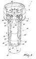
- the reference numeral 1 designates an antitheft device, particularly for preventing the drawing of fuel, schematically designated by the reference numeral 2, from tanks (not shown) which are provided with a fuel access adapter 3.
- the device comprises means adapted to allow, once the antitheft device 1 has been inserted and rotated partially within the adapter 3, nonremovable interconnection with respect to the adapter 3.
- Such means comprise a first ring 4, which is fixed and jointly connected both to the end of a tube 5, which protrudes downward and axially from it, and to a second ring 6, which is arranged coaxially to the tube 5 and is coupled thereto.
- a first gasket 10, advantageously of the cup-shaped type, is interposed between the lower surface, which is annular, of the first ring 4 and the underlying second ring 6, and in the condition in which the device 1 is inserted in the adapter 3 the gasket interacts partially with the upper surface 11 of the adapter 3.
- the first gasket 10 also interacts, in the central region that does not interact with the surface 11, with an underlying third ring 12, which can be arranged above the underlying second ring 6, which can rotate with respect to the third ring 12.
- the cone 9 has, in an upper region, a tip 13 that is directed toward the funnel 8 and is adapted to improve the behavior of the flow of fuel.
- the cone 9 has, at its base 14, an outside diameter that is slightly smaller than the inside diameter of the tube 5 so as to form an output section 15 for the passage of fuel.
- a tubular internal guide 16 is present coaxially with the cone 9, so as to also affect the overlying region of the tip 13, surrounds externally and in an upper region the outer surface of the funnel 8, and rests on, and is coupled to, the tube 5 and to the second ring 6.
- the internal guide 16 extends axially, following internally the shape of the cone 9 so as to form, together with said cone, a path for the fuel which is adapted to form a fluid stream.
- the stability of the position of the internal guide 16 is achieved because said guide has, at its lower end 17, an annular ridge 18 that rests on the inner lateral surface of the tube 5.
- a guide 19 for a float 20 is associated slidably, externally to the tube 5, at the region affected by the cone 9; the float 20 is adapted to move between a closed condition and an open condition of the output section 15.
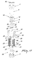
- the guide 19 has a cage-like shape, advantageously provided in two parts that can be mutually coupled, and has, on the lateral surface, proximate to its lower end 21, first openings 22 and second openings 23, which are adapted to allow the outflow of the fuel and are preferably annular.
- First screws 25 act at the two pairs of preset third openings 24 and are associated with the tube 5 and protrude radially from it and are further connected to suitable seats formed in four diametrical ribs 26, which protrude axially with respect to the outer lateral surface of the cone 9 at its base 14.
- the first screws 25 ensure correct axial positioning of the cone 9 with respect to the tube 5.
- the float 20 is substantially cylindrical and has, at its upper end 26, a second frustum-shaped gasket 27, which is adapted to interact with the overlying lower perimetric edge 28 of the tube 5, so as to block the passage of the fuel 2.
- the float 20 has, proximate to its lower end, an annular seat 29 for complementarily shaped teeth 30 that protrude radially and toward the inside of the guide 19 at its lower end 21, so as to allow the connection of the float 20 to the guide 19.
- the device comprises means that make it possible to fill the tank even beyond the level of arrangement of the float 20 in the inactive condition.
- Such means consist of four retractable tabs 31, each of which is substantially S-shaped in plan view, so as to form an upper wing 32 and a lower wing 33, between which a tooth 34 is provided and protrudes which is beak-shaped and therefore has an arc-like upper edge 35.
- Each one of the teeth 34 acts at appropriately provided grooves 36 formed axially with respect to the funnel 8 at the lower end 37 thereof, so as to allow the positioning of the teeth 34 inside the funnel 8 in a region above the tip 13 of the cone 9.
- the lower end 37 of the funnel 8 is connected at an appropriately provided seat formed on the internal guide 16, so as to form a continuous duct for the inflow of fuel.
- the grooves 36 can affect partially the internal guide 16.
- the teeth 34 are retractable by way of the fact that the upper wing 32 is coupled rotatably to an adapted ridge 38 arranged in the internal guide 16 adjacent to the outer lateral surface of the funnel 8.
- each tooth 34 is forced so as to keep the teeth 34 at the fuel inflow duct by means of an adapted elastic element 39 that wraps around all of the teeth 34.
- the retractable tabs 31 are accommodated at an adapted compartment 16a provided on the internal guide 16 at its upper end.
- a third gasket 40 can be arranged at the first ring 4.
- the position of the retractable tabs 31 can be modified from the stable condition shown in Figures 2 and 3 by the insertion of the fuel dispensing nozzle 41, which, as in the example shown in Figure 7 , interacts with the arc-like upper edge 35 of each tooth 34, forcing it to rotate until it lies within each groove 36.
- the condition in which the lower wing 33 protrudes at the fourth openings 42 the condition can occur, as described hereinafter, in which the lower wings 33 affect adapted fifth openings 43 provided on the guide 19 adjacent to its upper end 44.
- the nozzle pushes the teeth 34 of the retractable tabs 31 so that they rotate and make the lower wings 33 protrude at the fourth openings 42, thus allowing fuel dispensing.
- Figure 8 already illustrates the initial movement performed by the float 20 as the fuel flows into the tank.
- the fuel can flow by means of the fact that the output section 15 is clear, since the second gasket 27 of the float 20 does not interact with the lower perimetric edge 28 of the tube 5.
- the fuel reaches, at a certain point, a level that can even rise above the float, due to the longitudinal extension of the device 1 inside the tank: in this condition, shown in Figures 9 and 10 , the float still remains in such a condition as to allow the flow of fuel, since the output section 15 for the passage of fuel is still clear.
- the retractable tabs 31 are forced by the elastic element 39 so that the lower wings 33 no longer affect the fourth openings 42 and therefore the fifth openings 43, and this allows the float 20 to rise further, also pushing the guide 19, whose upper end 44 is no longer blocked by the lower wings 33 of the retractable tabs 31, so that the output section 15 for the passage of fuel is blocked.
- the invention has achieved the intended aim and objects, a device having been devised which makes it possible to avoid fuel theft from tanks, at the same time allowing optimum and quick dispensing of fuel during insertion at the pump.
- the antitheft device which can be anchored rapidly, safely and easily to the inlet of the tank, is structurally simple and has low production costs.
Landscapes
- Engineering & Computer Science (AREA)
- Life Sciences & Earth Sciences (AREA)
- Sustainable Development (AREA)
- Sustainable Energy (AREA)
- Chemical & Material Sciences (AREA)
- Combustion & Propulsion (AREA)
- Transportation (AREA)
- Mechanical Engineering (AREA)
- Cooling, Air Intake And Gas Exhaust, And Fuel Tank Arrangements In Propulsion Units (AREA)
- Burglar Alarm Systems (AREA)
- Loading And Unloading Of Fuel Tanks Or Ships (AREA)
Applications Claiming Priority (1)
| Application Number | Priority Date | Filing Date | Title |
|---|---|---|---|
| ITTV2008A000119A IT1391204B1 (it) | 2008-09-22 | 2008-09-22 | Dispositivo antifurto, particolarmente per impedire la estrazione di carburante da serbatoi |
Publications (2)
| Publication Number | Publication Date |
|---|---|
| EP2165873A1 true EP2165873A1 (de) | 2010-03-24 |
| EP2165873B1 EP2165873B1 (de) | 2011-04-27 |
Family
ID=41227174
Family Applications (1)
| Application Number | Title | Priority Date | Filing Date |
|---|---|---|---|
| EP09169758A Active EP2165873B1 (de) | 2008-09-22 | 2009-09-08 | Diebstahlschutzvorrichtung, insbesondere zum Vorbeugen des Absaugens von Kraftstoff aus Tanks |
Country Status (5)
| Country | Link |
|---|---|
| EP (1) | EP2165873B1 (de) |
| AT (1) | ATE507102T1 (de) |
| DE (1) | DE602009001163D1 (de) |
| ES (1) | ES2365830T3 (de) |
| IT (1) | IT1391204B1 (de) |
Cited By (8)
| Publication number | Priority date | Publication date | Assignee | Title |
|---|---|---|---|---|
| GB2476954A (en) * | 2010-01-14 | 2011-07-20 | Tiss Ltd | Anti siphon device |
| KR101326495B1 (ko) | 2012-08-24 | 2013-11-08 | 현대자동차주식회사 | 차량의 엘피지 충전 커플러 |
| ITMO20130042A1 (it) * | 2013-02-21 | 2014-08-22 | Laure Descat | Dispositivo antifurto |
| ITMO20130041A1 (it) * | 2013-02-21 | 2014-08-22 | Laure Descat | Dispositivo antifurto provvisto di mezzi di fissaggio. |
| CN104786828A (zh) * | 2015-05-09 | 2015-07-22 | 赵晓强 | 一种提拉式油箱防盗器 |
| WO2016001330A1 (en) * | 2014-07-04 | 2016-01-07 | Lago Accessori S.R.L. | Anti-siphoning device, particularly for preventing the extraction of fuel from tanks |
| WO2017158383A1 (en) * | 2016-03-18 | 2017-09-21 | Bute Technology Ltd | Apparatus for use as an anti-siphon device and method |
| WO2020035702A1 (en) * | 2018-08-17 | 2020-02-20 | Tiss Limited | Improved obstruction design |
Families Citing this family (1)
| Publication number | Priority date | Publication date | Assignee | Title |
|---|---|---|---|---|
| GB0806811D0 (en) | 2008-04-15 | 2008-05-14 | Tiss Ltd | Anti siphon tank inlet |
Citations (6)
| Publication number | Priority date | Publication date | Assignee | Title |
|---|---|---|---|---|
| DE870072C (de) * | 1951-03-21 | 1953-03-09 | Ernst Heinz Detering | Sicherungskoerper an Fluessigkeitsbehaeltern gegen Diebstahl des Inhalts, insbesondere an Kraftstoffbehaeltern fuer Automobile und Flugzeuge |
| US3951297A (en) * | 1974-05-06 | 1976-04-20 | Carlos A. Riquelme | Anti-siphon gas tank adaptor |
| US5025946A (en) * | 1990-07-29 | 1991-06-25 | Amoco Corporation | Anti-theft device for tank openings |
| EP1325830A1 (de) * | 2001-12-21 | 2003-07-09 | Philippe Mougenot | Diebstahlsicherungsvorrichtung und Überlaufschutz für Flüssigkeitsbehälter, insbesondere Kraftstofftank |
| DE202004012096U1 (de) * | 2004-07-27 | 2005-12-22 | Reutter Metallwarenfabrik Gmbh | Diebstahlschutz für Kraftstoffbehälter |
| WO2006048659A1 (en) * | 2004-11-03 | 2006-05-11 | Tiss Limited | Anti siphon tank inlet and method |
-
2008
- 2008-09-22 IT ITTV2008A000119A patent/IT1391204B1/it active
-
2009
- 2009-09-08 EP EP09169758A patent/EP2165873B1/de active Active
- 2009-09-08 DE DE602009001163T patent/DE602009001163D1/de active Active
- 2009-09-08 AT AT09169758T patent/ATE507102T1/de not_active IP Right Cessation
- 2009-09-08 ES ES09169758T patent/ES2365830T3/es active Active
Patent Citations (6)
| Publication number | Priority date | Publication date | Assignee | Title |
|---|---|---|---|---|
| DE870072C (de) * | 1951-03-21 | 1953-03-09 | Ernst Heinz Detering | Sicherungskoerper an Fluessigkeitsbehaeltern gegen Diebstahl des Inhalts, insbesondere an Kraftstoffbehaeltern fuer Automobile und Flugzeuge |
| US3951297A (en) * | 1974-05-06 | 1976-04-20 | Carlos A. Riquelme | Anti-siphon gas tank adaptor |
| US5025946A (en) * | 1990-07-29 | 1991-06-25 | Amoco Corporation | Anti-theft device for tank openings |
| EP1325830A1 (de) * | 2001-12-21 | 2003-07-09 | Philippe Mougenot | Diebstahlsicherungsvorrichtung und Überlaufschutz für Flüssigkeitsbehälter, insbesondere Kraftstofftank |
| DE202004012096U1 (de) * | 2004-07-27 | 2005-12-22 | Reutter Metallwarenfabrik Gmbh | Diebstahlschutz für Kraftstoffbehälter |
| WO2006048659A1 (en) * | 2004-11-03 | 2006-05-11 | Tiss Limited | Anti siphon tank inlet and method |
Cited By (14)
| Publication number | Priority date | Publication date | Assignee | Title |
|---|---|---|---|---|
| GB2476954A (en) * | 2010-01-14 | 2011-07-20 | Tiss Ltd | Anti siphon device |
| KR101326495B1 (ko) | 2012-08-24 | 2013-11-08 | 현대자동차주식회사 | 차량의 엘피지 충전 커플러 |
| ITMO20130042A1 (it) * | 2013-02-21 | 2014-08-22 | Laure Descat | Dispositivo antifurto |
| ITMO20130041A1 (it) * | 2013-02-21 | 2014-08-22 | Laure Descat | Dispositivo antifurto provvisto di mezzi di fissaggio. |
| CN106687324A (zh) * | 2014-07-04 | 2017-05-17 | 意大利纳格卡车配件有限公司 | 防虹吸设备,特别用于防止从储罐抽取燃料 |
| WO2016001330A1 (en) * | 2014-07-04 | 2016-01-07 | Lago Accessori S.R.L. | Anti-siphoning device, particularly for preventing the extraction of fuel from tanks |
| CN106687324B (zh) * | 2014-07-04 | 2019-01-18 | 意大利纳格卡车配件有限公司 | 用于防止从储罐抽取燃料的防虹吸设备 |
| US10266049B2 (en) | 2014-07-04 | 2019-04-23 | Lago Accessori S.R.L. | Anti-siphoning device, particularly for preventing the extraction of fuel from tanks |
| CN104786828A (zh) * | 2015-05-09 | 2015-07-22 | 赵晓强 | 一种提拉式油箱防盗器 |
| CN104786828B (zh) * | 2015-05-09 | 2017-07-11 | 王俊美 | 一种提拉式油箱防盗器 |
| WO2017158383A1 (en) * | 2016-03-18 | 2017-09-21 | Bute Technology Ltd | Apparatus for use as an anti-siphon device and method |
| GB2564792A (en) * | 2016-03-18 | 2019-01-23 | Bute Tech Ltd | Apparatus for use as an anti-siphon device and method |
| WO2020035702A1 (en) * | 2018-08-17 | 2020-02-20 | Tiss Limited | Improved obstruction design |
| US11938808B2 (en) | 2018-08-17 | 2024-03-26 | Tiss Limited | Obstruction design |
Also Published As
| Publication number | Publication date |
|---|---|
| ATE507102T1 (de) | 2011-05-15 |
| ITTV20080119A1 (it) | 2010-03-23 |
| DE602009001163D1 (de) | 2011-06-09 |
| EP2165873B1 (de) | 2011-04-27 |
| IT1391204B1 (it) | 2011-11-18 |
| ES2365830T3 (es) | 2011-10-11 |
Similar Documents
| Publication | Publication Date | Title |
|---|---|---|
| EP2165873B1 (de) | Diebstahlschutzvorrichtung, insbesondere zum Vorbeugen des Absaugens von Kraftstoff aus Tanks | |
| US11673793B2 (en) | Fluid dispensing device with tapered nozzle | |
| US7584766B2 (en) | Overfill prevention valve for shallow tanks | |
| RU2631757C2 (ru) | Устройство заправочной горловины для бака для текучей среды | |
| JP2525771Y2 (ja) | 自動車用燃料逆流防止装置 | |
| DE102013018194A1 (de) | Kraftstoffabsperrventil | |
| JP6591418B2 (ja) | ドレン装置 | |
| JP5518401B2 (ja) | 計量注出容器 | |
| EP2419191B1 (de) | Filtervorrichtung | |
| CN108496035A (zh) | 具有伸缩活塞的高压阀 | |
| US8210497B2 (en) | Double water-seal accumulator for perfume dispenser | |
| AU2003241639A1 (en) | Filler tube mounted fuel tank refueling valve | |
| US6302305B1 (en) | Pump intended to be fitted to a container | |
| US20100175760A1 (en) | Float valve | |
| JP4435242B2 (ja) | ポンプ装置 | |
| EP3164287B1 (de) | Absaugschutzvorrichtung, insbesondere zur vermeidung der extraktion von kraftstoff aus tanks | |
| EP3385586B1 (de) | Luftrückhalteventil für druckwasserbehälter | |
| WO1995028335A1 (en) | Vented pour spout automatically accommodating of fluid viscosity | |
| JP4435243B2 (ja) | ポンプ装置 | |
| EP2206179B1 (de) | Wassernachfüllstopfen für batteriezellen | |
| CN109026872A (zh) | 一种插装阀 | |
| US11938808B2 (en) | Obstruction design | |
| JP4643515B2 (ja) | フロート弁を備えた燃料油のポンプユニット | |
| DE102014108088A1 (de) | Flüssigkeitstank eines Kraftfahrzeugs |
Legal Events
| Date | Code | Title | Description |
|---|---|---|---|
| PUAI | Public reference made under article 153(3) epc to a published international application that has entered the european phase |
Free format text: ORIGINAL CODE: 0009012 |
|
| AK | Designated contracting states |
Kind code of ref document: A1 Designated state(s): AT BE BG CH CY CZ DE DK EE ES FI FR GB GR HR HU IE IS IT LI LT LU LV MC MK MT NL NO PL PT RO SE SI SK SM TR |
|
| AX | Request for extension of the european patent |
Extension state: AL BA RS |
|
| GRAP | Despatch of communication of intention to grant a patent |
Free format text: ORIGINAL CODE: EPIDOSNIGR1 |
|
| 17P | Request for examination filed |
Effective date: 20100923 |
|
| GRAS | Grant fee paid |
Free format text: ORIGINAL CODE: EPIDOSNIGR3 |
|
| GRAA | (expected) grant |
Free format text: ORIGINAL CODE: 0009210 |
|
| AK | Designated contracting states |
Kind code of ref document: B1 Designated state(s): AT BE BG CH CY CZ DE DK EE ES FI FR GB GR HR HU IE IS IT LI LT LU LV MC MK MT NL NO PL PT RO SE SI SK SM TR |
|
| REG | Reference to a national code |
Ref country code: GB Ref legal event code: FG4D |
|
| REG | Reference to a national code |
Ref country code: CH Ref legal event code: EP |
|
| REG | Reference to a national code |
Ref country code: IE Ref legal event code: FG4D |
|
| REF | Corresponds to: |
Ref document number: 602009001163 Country of ref document: DE Date of ref document: 20110609 Kind code of ref document: P |
|
| REG | Reference to a national code |
Ref country code: DE Ref legal event code: R096 Ref document number: 602009001163 Country of ref document: DE Effective date: 20110609 |
|
| REG | Reference to a national code |
Ref country code: NL Ref legal event code: T3 |
|
| LTIE | Lt: invalidation of european patent or patent extension |
Effective date: 20110427 |
|
| REG | Reference to a national code |
Ref country code: ES Ref legal event code: FG2A Ref document number: 2365830 Country of ref document: ES Kind code of ref document: T3 Effective date: 20111011 |
|
| PG25 | Lapsed in a contracting state [announced via postgrant information from national office to epo] |
Ref country code: PT Free format text: LAPSE BECAUSE OF FAILURE TO SUBMIT A TRANSLATION OF THE DESCRIPTION OR TO PAY THE FEE WITHIN THE PRESCRIBED TIME-LIMIT Effective date: 20110829 Ref country code: SE Free format text: LAPSE BECAUSE OF FAILURE TO SUBMIT A TRANSLATION OF THE DESCRIPTION OR TO PAY THE FEE WITHIN THE PRESCRIBED TIME-LIMIT Effective date: 20110427 Ref country code: LT Free format text: LAPSE BECAUSE OF FAILURE TO SUBMIT A TRANSLATION OF THE DESCRIPTION OR TO PAY THE FEE WITHIN THE PRESCRIBED TIME-LIMIT Effective date: 20110427 Ref country code: NO Free format text: LAPSE BECAUSE OF FAILURE TO SUBMIT A TRANSLATION OF THE DESCRIPTION OR TO PAY THE FEE WITHIN THE PRESCRIBED TIME-LIMIT Effective date: 20110727 Ref country code: HR Free format text: LAPSE BECAUSE OF FAILURE TO SUBMIT A TRANSLATION OF THE DESCRIPTION OR TO PAY THE FEE WITHIN THE PRESCRIBED TIME-LIMIT Effective date: 20110427 |
|
| PG25 | Lapsed in a contracting state [announced via postgrant information from national office to epo] |
Ref country code: IS Free format text: LAPSE BECAUSE OF FAILURE TO SUBMIT A TRANSLATION OF THE DESCRIPTION OR TO PAY THE FEE WITHIN THE PRESCRIBED TIME-LIMIT Effective date: 20110827 Ref country code: FI Free format text: LAPSE BECAUSE OF FAILURE TO SUBMIT A TRANSLATION OF THE DESCRIPTION OR TO PAY THE FEE WITHIN THE PRESCRIBED TIME-LIMIT Effective date: 20110427 Ref country code: CY Free format text: LAPSE BECAUSE OF FAILURE TO SUBMIT A TRANSLATION OF THE DESCRIPTION OR TO PAY THE FEE WITHIN THE PRESCRIBED TIME-LIMIT Effective date: 20110427 Ref country code: LV Free format text: LAPSE BECAUSE OF FAILURE TO SUBMIT A TRANSLATION OF THE DESCRIPTION OR TO PAY THE FEE WITHIN THE PRESCRIBED TIME-LIMIT Effective date: 20110427 Ref country code: BE Free format text: LAPSE BECAUSE OF FAILURE TO SUBMIT A TRANSLATION OF THE DESCRIPTION OR TO PAY THE FEE WITHIN THE PRESCRIBED TIME-LIMIT Effective date: 20110427 Ref country code: AT Free format text: LAPSE BECAUSE OF FAILURE TO SUBMIT A TRANSLATION OF THE DESCRIPTION OR TO PAY THE FEE WITHIN THE PRESCRIBED TIME-LIMIT Effective date: 20110427 Ref country code: SI Free format text: LAPSE BECAUSE OF FAILURE TO SUBMIT A TRANSLATION OF THE DESCRIPTION OR TO PAY THE FEE WITHIN THE PRESCRIBED TIME-LIMIT Effective date: 20110427 Ref country code: GR Free format text: LAPSE BECAUSE OF FAILURE TO SUBMIT A TRANSLATION OF THE DESCRIPTION OR TO PAY THE FEE WITHIN THE PRESCRIBED TIME-LIMIT Effective date: 20110728 |
|
| PG25 | Lapsed in a contracting state [announced via postgrant information from national office to epo] |
Ref country code: EE Free format text: LAPSE BECAUSE OF FAILURE TO SUBMIT A TRANSLATION OF THE DESCRIPTION OR TO PAY THE FEE WITHIN THE PRESCRIBED TIME-LIMIT Effective date: 20110427 |
|
| PG25 | Lapsed in a contracting state [announced via postgrant information from national office to epo] |
Ref country code: SK Free format text: LAPSE BECAUSE OF FAILURE TO SUBMIT A TRANSLATION OF THE DESCRIPTION OR TO PAY THE FEE WITHIN THE PRESCRIBED TIME-LIMIT Effective date: 20110427 Ref country code: PL Free format text: LAPSE BECAUSE OF FAILURE TO SUBMIT A TRANSLATION OF THE DESCRIPTION OR TO PAY THE FEE WITHIN THE PRESCRIBED TIME-LIMIT Effective date: 20110427 |
|
| PLBE | No opposition filed within time limit |
Free format text: ORIGINAL CODE: 0009261 |
|
| STAA | Information on the status of an ep patent application or granted ep patent |
Free format text: STATUS: NO OPPOSITION FILED WITHIN TIME LIMIT |
|
| 26N | No opposition filed |
Effective date: 20120130 |
|
| PG25 | Lapsed in a contracting state [announced via postgrant information from national office to epo] |
Ref country code: MC Free format text: LAPSE BECAUSE OF NON-PAYMENT OF DUE FEES Effective date: 20110930 |
|
| REG | Reference to a national code |
Ref country code: DE Ref legal event code: R097 Ref document number: 602009001163 Country of ref document: DE Effective date: 20120130 |
|
| REG | Reference to a national code |
Ref country code: IE Ref legal event code: MM4A |
|
| PG25 | Lapsed in a contracting state [announced via postgrant information from national office to epo] |
Ref country code: IE Free format text: LAPSE BECAUSE OF NON-PAYMENT OF DUE FEES Effective date: 20110908 |
|
| PG25 | Lapsed in a contracting state [announced via postgrant information from national office to epo] |
Ref country code: MT Free format text: LAPSE BECAUSE OF FAILURE TO SUBMIT A TRANSLATION OF THE DESCRIPTION OR TO PAY THE FEE WITHIN THE PRESCRIBED TIME-LIMIT Effective date: 20110427 Ref country code: MK Free format text: LAPSE BECAUSE OF FAILURE TO SUBMIT A TRANSLATION OF THE DESCRIPTION OR TO PAY THE FEE WITHIN THE PRESCRIBED TIME-LIMIT Effective date: 20110427 |
|
| PG25 | Lapsed in a contracting state [announced via postgrant information from national office to epo] |
Ref country code: SM Free format text: LAPSE BECAUSE OF FAILURE TO SUBMIT A TRANSLATION OF THE DESCRIPTION OR TO PAY THE FEE WITHIN THE PRESCRIBED TIME-LIMIT Effective date: 20110427 |
|
| PG25 | Lapsed in a contracting state [announced via postgrant information from national office to epo] |
Ref country code: LU Free format text: LAPSE BECAUSE OF NON-PAYMENT OF DUE FEES Effective date: 20110908 |
|
| PG25 | Lapsed in a contracting state [announced via postgrant information from national office to epo] |
Ref country code: BG Free format text: LAPSE BECAUSE OF FAILURE TO SUBMIT A TRANSLATION OF THE DESCRIPTION OR TO PAY THE FEE WITHIN THE PRESCRIBED TIME-LIMIT Effective date: 20110727 |
|
| PG25 | Lapsed in a contracting state [announced via postgrant information from national office to epo] |
Ref country code: TR Free format text: LAPSE BECAUSE OF FAILURE TO SUBMIT A TRANSLATION OF THE DESCRIPTION OR TO PAY THE FEE WITHIN THE PRESCRIBED TIME-LIMIT Effective date: 20110427 |
|
| PG25 | Lapsed in a contracting state [announced via postgrant information from national office to epo] |
Ref country code: HU Free format text: LAPSE BECAUSE OF FAILURE TO SUBMIT A TRANSLATION OF THE DESCRIPTION OR TO PAY THE FEE WITHIN THE PRESCRIBED TIME-LIMIT Effective date: 20110427 |
|
| REG | Reference to a national code |
Ref country code: CH Ref legal event code: PL |
|
| PG25 | Lapsed in a contracting state [announced via postgrant information from national office to epo] |
Ref country code: LI Free format text: LAPSE BECAUSE OF NON-PAYMENT OF DUE FEES Effective date: 20130930 Ref country code: CH Free format text: LAPSE BECAUSE OF NON-PAYMENT OF DUE FEES Effective date: 20130930 |
|
| REG | Reference to a national code |
Ref country code: DE Ref legal event code: R082 Ref document number: 602009001163 Country of ref document: DE Representative=s name: GRAMM, LINS & PARTNER PATENT- UND RECHTSANWAEL, DE |
|
| REG | Reference to a national code |
Ref country code: FR Ref legal event code: PLFP Year of fee payment: 8 |
|
| REG | Reference to a national code |
Ref country code: FR Ref legal event code: PLFP Year of fee payment: 9 |
|
| REG | Reference to a national code |
Ref country code: FR Ref legal event code: PLFP Year of fee payment: 10 |
|
| P01 | Opt-out of the competence of the unified patent court (upc) registered |
Effective date: 20230528 |
|
| PGFP | Annual fee paid to national office [announced via postgrant information from national office to epo] |
Ref country code: NL Payment date: 20230926 Year of fee payment: 15 Ref country code: IT Payment date: 20230915 Year of fee payment: 15 Ref country code: GB Payment date: 20230918 Year of fee payment: 15 Ref country code: CZ Payment date: 20230828 Year of fee payment: 15 |
|
| PGFP | Annual fee paid to national office [announced via postgrant information from national office to epo] |
Ref country code: FR Payment date: 20230918 Year of fee payment: 15 Ref country code: DE Payment date: 20230905 Year of fee payment: 15 |
|
| PGFP | Annual fee paid to national office [announced via postgrant information from national office to epo] |
Ref country code: ES Payment date: 20231020 Year of fee payment: 15 |