EP2165396B1 - Verfahren und anordnung zur gleichmässigen impulsstromaufteilung bei parallel geschalteten, spannungsschaltenden überspannungsableitern - Google Patents
Verfahren und anordnung zur gleichmässigen impulsstromaufteilung bei parallel geschalteten, spannungsschaltenden überspannungsableitern Download PDFInfo
- Publication number
- EP2165396B1 EP2165396B1 EP08750034A EP08750034A EP2165396B1 EP 2165396 B1 EP2165396 B1 EP 2165396B1 EP 08750034 A EP08750034 A EP 08750034A EP 08750034 A EP08750034 A EP 08750034A EP 2165396 B1 EP2165396 B1 EP 2165396B1
- Authority
- EP
- European Patent Office
- Prior art keywords
- voltage
- arresters
- ignition
- surge
- parallel
- Prior art date
- Legal status (The legal status is an assumption and is not a legal conclusion. Google has not performed a legal analysis and makes no representation as to the accuracy of the status listed.)
- Not-in-force
Links
- 238000000034 method Methods 0.000 title claims abstract description 16
- 230000003068 static effect Effects 0.000 claims description 7
- 230000003111 delayed effect Effects 0.000 claims description 3
- 206010042255 Struck by lightning Diseases 0.000 abstract 1
- 238000000926 separation method Methods 0.000 description 21
- 239000000463 material Substances 0.000 description 5
- 230000001419 dependent effect Effects 0.000 description 2
- 230000002829 reductive effect Effects 0.000 description 2
- 235000001674 Agaricus brunnescens Nutrition 0.000 description 1
- OKTJSMMVPCPJKN-UHFFFAOYSA-N Carbon Chemical compound [C] OKTJSMMVPCPJKN-UHFFFAOYSA-N 0.000 description 1
- RYGMFSIKBFXOCR-UHFFFAOYSA-N Copper Chemical compound [Cu] RYGMFSIKBFXOCR-UHFFFAOYSA-N 0.000 description 1
- 229910000831 Steel Inorganic materials 0.000 description 1
- 230000015572 biosynthetic process Effects 0.000 description 1
- 229910052802 copper Inorganic materials 0.000 description 1
- 239000010949 copper Substances 0.000 description 1
- 230000007423 decrease Effects 0.000 description 1
- 238000009795 derivation Methods 0.000 description 1
- 238000011161 development Methods 0.000 description 1
- 230000018109 developmental process Effects 0.000 description 1
- 238000010586 diagram Methods 0.000 description 1
- 230000000694 effects Effects 0.000 description 1
- 230000005684 electric field Effects 0.000 description 1
- 230000002349 favourable effect Effects 0.000 description 1
- 238000010304 firing Methods 0.000 description 1
- 229910002804 graphite Inorganic materials 0.000 description 1
- 239000010439 graphite Substances 0.000 description 1
- 230000000670 limiting effect Effects 0.000 description 1
- 230000036961 partial effect Effects 0.000 description 1
- 230000001681 protective effect Effects 0.000 description 1
- 239000010959 steel Substances 0.000 description 1
Images

Classifications
-
- H—ELECTRICITY
- H01—ELECTRIC ELEMENTS
- H01T—SPARK GAPS; OVERVOLTAGE ARRESTERS USING SPARK GAPS; SPARKING PLUGS; CORONA DEVICES; GENERATING IONS TO BE INTRODUCED INTO NON-ENCLOSED GASES
- H01T4/00—Overvoltage arresters using spark gaps
- H01T4/10—Overvoltage arresters using spark gaps having a single gap or a plurality of gaps in parallel
- H01T4/12—Overvoltage arresters using spark gaps having a single gap or a plurality of gaps in parallel hermetically sealed
Definitions
- the invention relates to a method and an arrangement for uniform pulse current distribution in parallel, voltage-switching surge arresters, such as gas discharge arresters, spark gaps with ignition aids or the like, for the purpose of increasing the lightning current carrying capacity according to the preamble of patent claims 1 and 7 respectively.
- the surge arresters have an ignition delay time with a time-limited residual voltage, i. the voltage at current flow, which is higher by a defined amount than the static response voltage of the surge arrester or a portion of the arrester or an ignition aid, preferably at all surge loads, but at least at currents with the slope of the rated surge current load.
- the delay time i. the duration of the increased residual voltage up to the ignition of the main separation section or main spark gap at rated surge load should be in the range of 100 ns to 200 ns, with lower loads and delay times up to several microseconds without limiting the desired function are possible.
- the proposed measure causes after the response of the first surge arrester, the voltage in the parallel circuit increases until all other surge arresters have also addressed. This applies preferably to all surge current loads, but at least for currents with the slope of the rated surge current load.
- the surge arresters used in the parallel circuit have a delay time to ignition between the main electrodes and the main separation, wherein within the delay time, a voltage is built up at momentum current flow which is at least between 10% and 20% higher than the static response voltage of the surge arrester used or an existing starting aid.
- the ignition delay of the line between the main electrodes is generated by at least one integrated in the respective arrester impedance or an integrated resistor.
- the integrated impedance After ignition of the main line of the spark gap, the integrated impedance is no longer considered part of the circuit, i. there are no repercussions in the sense of a voltage drop on the circuit. This is a significant difference to external impedances, but also to impedance-dependent terminals of the spark gap within a trap housing, e.g. when connecting via steel or graphite elements instead of copper cables.
- the elements used for ignition delay have in particular a non-linear current-voltage behavior.
- the delay time and the voltage build-up for safe ignition of all arresters of the parallel circuit is realized by an integrated impedance-sensitive auxiliary electrode, which forms a first separation distance L1 between the main electrodes, which is smaller than the second separation distance L2 between the main electrodes, so that in a current flow along the auxiliary electrode over the first separation distance L1, a voltage drop arises, which increases linearly or nonlinearly with increasing current flow.
- the arrangement for carrying out the method according to the invention for uniform pulse current distribution in parallel, voltage-switching surge arresters is designed such that the arresters connected in parallel each have at least one main separation path L2 between the main electrodes, an impedance-affected one between the main electrodes
- Auxiliary electrode also in different geometric configuration, is arranged so that an auxiliary separation path L1 is formed, whose length is smaller than that of the main separation section L2, in order to achieve overvoltage response first via the auxiliary electrode and the auxiliary separation path L1, which is characterized by the current flow through or along the auxiliary electrode results in a voltage drop, which allows the response of the parallel-connected arrester within the delayed ignition of the main separation section L2.
- the required voltage drop for the ignition of the parallel arresters is generated by an ignition delay of the main separation path which is integrated in the arrester. This can be done on the one hand by the geometric design of the ignition and the discharge space and on the other hand by the specified properties of the materials in the first ignition, ie based on the auxiliary electrode.
- the ignition delay fulfills several tasks. Due to the delay of the ignition of the main separation line a voltage drop is generated, which according to the invention is at current grades of the rated surge currents to 10% to 20%, preferably 15% above the static threshold of the parallel arrester.
- the duration of the pending voltage drop is to be chosen even greater than the usual firing times of voltage-switching surge arresters with a voltage drop in the amount of the desired protection level.
- the Zündverzugs committee the main line are preferably in the range> 100 ns lying to ensure a safe ignition of the parallel arrester.
- the magnitude of the voltage drop can be reduced to a minimum value since the parallel arresters can respond according to their static characteristic.
- the parallel arresters can respond according to their static characteristic.
- a non-linear current-voltage behavior of the delay elements is preferred.
- the task of the ignition delay of the main spark gap and the control of the voltage drop can also be partially taken over by this.
- FIG. 1 Let us explain the basic behavior of two parallel-connected overvoltage arresters according to the invention.
- the curve shows the increase in the overvoltage, with the dashed curves 2 and 3 representing the surge characteristic of the arrester.
- the first arrester Upon reaching the surge characteristic of the first arrester at point 4, the first arrester responds and the pulse current begins to flow over the section of this first arrester.
- one of the two spark gaps ignites at time t3 and the voltage is reduced to the arc voltage of the main line of the corresponding arrester.
- the second arrester Due to the charge introduced, the associated ionization of the second arrester and the limited commutation time of the current, the second arrester also ignites. With identical arresters results due to the similar arc voltage at surge load in accordance with the principles of the invention, an almost equal current distribution.
- High arc voltages in the range> 100 V have a particularly favorable effect on the current distribution. These arc voltages allow ideal current sharing even with pulses with long back half-lives.
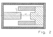
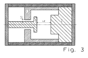
- Fig. 2 and 3 show possible embodiments of the invention further developed surge arrester.
- the opposing main electrodes 1 and 2 are provided with a main separating path L2 therebetween.
- the auxiliary electrode 3 can be electrically connected to one of the main electrodes 1 or 2 be connected or even isolated from two main electrodes by a separation path.
- the auxiliary electrode 3 is electrically conductively connected to the main electrode 2 and separated from the opposed main electrode 1 by a separating gap L1.
- the auxiliary separation distance L1 is smaller or shorter than the separation distance L2 and ensures the response of the arrester between the main electrode 1 and the auxiliary electrode 3 due to the distance and / or the material selection in all steepnesses.
- the arrester thus responds via the main electrode 2, the auxiliary electrode 3 and the main electrode 1.
- the material of the auxiliary electrode is impedance-affected, so that a current flow through or along the material results in a voltage drop which increases linearly or non-linearly as the current flow or current change increases.
- the current across the auxiliary electrode 3 can reach instantaneous values of up to several kA.
- the time to ignition of the main separation path L2 depends on the ionization between the main separation path L2 and the magnitude of the voltage drop over the entire arrester, in addition to the typical derivation factors such as distance, material, pressure, electric field strength and so on.
- the Fig. 3 shows an embodiment of a surge arrester, in which the arrangement of the first discharge path L1, the ionization of the main discharge path L2 is difficult, whereby the time delay can be increased to the ignition of the main line L2, regardless of the characteristics of the auxiliary electrode 3.
- Fig. 3 is the first main electrode 1 provided with a mushroom or nail-shaped head, which is opposite to the main electrode 2.
- finger-like extensions of the auxiliary electrode 3 are provided, which virtually pass behind the actual head, which have a distance from the main electrode 1, which forms the auxiliary separation path L1.
- the length of the auxiliary separation route L1 is smaller than the distance between the main electrodes 1 and 2, which forms the main separating line L2.
- an impedance can also be applied outside the arrester and the potential can be supplied via a conducting auxiliary electrode.
- the invention allows a parallel connection of gas discharge arresters, spark gaps and surge arresters with ignition aid to increase the lightning current carrying capacity, with a safe distribution of the lightning surge current to the arrester, so that an overload of individual arresters can be excluded within the parallel circuit.
- the parallel connection can be realized at any time, even subsequently and without additional series elements with the desired, optimal current distribution at surge loads.
Landscapes
- Emergency Protection Circuit Devices (AREA)
- Generation Of Surge Voltage And Current (AREA)
Priority Applications (1)
| Application Number | Priority Date | Filing Date | Title |
|---|---|---|---|
| PL08750034T PL2165396T3 (pl) | 2007-07-11 | 2008-05-05 | Sposób i układ do jednorodnego podziału prądu pulsacyjnego w przypadku równolegle włączonych ochronników przepięciowych przełączanych napięciem |
Applications Claiming Priority (3)
| Application Number | Priority Date | Filing Date | Title |
|---|---|---|---|
| DE102007032298 | 2007-07-11 | ||
| DE102007042988A DE102007042988B4 (de) | 2007-07-11 | 2007-09-10 | Verfahren und Anordnung zur gleichmäßigen Impulsstromaufteilung bei parallel geschalteten, spannungsschaltenden Überspannungsableitern |
| PCT/EP2008/055473 WO2009007151A1 (de) | 2007-07-11 | 2008-05-05 | Verfahren und anordnung zur gleichmässigen impulsstromaufteilung bei parallel geschalteten, spannungsschaltenden überspannungsableitern |
Publications (2)
| Publication Number | Publication Date |
|---|---|
| EP2165396A1 EP2165396A1 (de) | 2010-03-24 |
| EP2165396B1 true EP2165396B1 (de) | 2010-11-17 |
Family
ID=40157440
Family Applications (1)
| Application Number | Title | Priority Date | Filing Date |
|---|---|---|---|
| EP08750034A Not-in-force EP2165396B1 (de) | 2007-07-11 | 2008-05-05 | Verfahren und anordnung zur gleichmässigen impulsstromaufteilung bei parallel geschalteten, spannungsschaltenden überspannungsableitern |
Country Status (7)
| Country | Link |
|---|---|
| EP (1) | EP2165396B1 (pl) |
| JP (1) | JP2010532912A (pl) |
| CN (1) | CN101765952B (pl) |
| AT (1) | ATE488892T1 (pl) |
| DE (2) | DE102007042988B4 (pl) |
| PL (1) | PL2165396T3 (pl) |
| WO (1) | WO2009007151A1 (pl) |
Families Citing this family (4)
| Publication number | Priority date | Publication date | Assignee | Title |
|---|---|---|---|---|
| CZ306224B6 (cs) * | 2012-08-22 | 2016-10-12 | Hakel Spol. S R. O. | Výkonová bleskojistka pro velké proudové zátěže, s prodlouženou životností |
| US9438221B2 (en) * | 2014-04-03 | 2016-09-06 | Infineon Technologies Ag | Switch device |
| DE102014015610B4 (de) * | 2014-10-23 | 2017-02-23 | Phoenix Contact Gmbh & Co. Kg | Überspannungsableiter |
| ES2594452B1 (es) * | 2015-06-17 | 2017-09-28 | Gamesa Innovation & Technology, S.L. | Sistema pararrayos para palas de aerogenerador con un área efectiva de inyección en laminados de fibra de carbono y una distribución equilibrada de la intensidad y el voltaje de las corrientes de rayo entre distintos caminos conductores |
Family Cites Families (9)
| Publication number | Priority date | Publication date | Assignee | Title |
|---|---|---|---|---|
| CH592973A5 (en) | 1976-03-05 | 1977-11-15 | Cerberus Ag | Staged voltage overload protection - has parallel suppression stages which consist of resistor and suppressor in series to provide staged triggering levels |
| DE3905799A1 (de) | 1989-02-24 | 1990-09-13 | Eltex Elektrostatik Gmbh | Hochspannungselektrode |
| DE19510181C1 (de) * | 1995-03-21 | 1996-06-05 | Dehn & Soehne | Anordnung zur Ableitung von Überspannungen und zur Löschung des Netzfolgestromes |
| DE19717802B4 (de) * | 1997-04-26 | 2009-09-17 | Dehn + Söhne GmbH + Co KG | Funkenstrecke |
| FR2766986B1 (fr) | 1997-08-01 | 1999-10-22 | Soule Materiel Electr | Perfectionnement en dispositif de protection contre les surtensions |
| DE19803636A1 (de) * | 1998-02-02 | 1999-08-05 | Phoenix Contact Gmbh & Co | Überspannungsschutzsystem |
| FR2864711B1 (fr) | 2003-12-30 | 2006-04-21 | Soule Protection Surtensions | Dispositif de protection contre les surtensions avec eclateurs en parallele a declenchement simultane |
| DE102004034895B4 (de) | 2004-07-19 | 2008-05-29 | Diehl Bgt Defence Gmbh & Co. Kg | Hochspannungsschalter und Verwendung desselben bei einem Mikrowellengenerator |
| CN100435446C (zh) * | 2005-08-11 | 2008-11-19 | 西安交通大学 | 真空环境下带引发电极的过电压保护装置 |
-
2007
- 2007-09-10 DE DE102007042988A patent/DE102007042988B4/de not_active Expired - Fee Related
-
2008
- 2008-05-05 DE DE502008001844T patent/DE502008001844D1/de active Active
- 2008-05-05 PL PL08750034T patent/PL2165396T3/pl unknown
- 2008-05-05 EP EP08750034A patent/EP2165396B1/de not_active Not-in-force
- 2008-05-05 CN CN2008800243275A patent/CN101765952B/zh not_active Expired - Fee Related
- 2008-05-05 JP JP2010515433A patent/JP2010532912A/ja not_active Withdrawn
- 2008-05-05 WO PCT/EP2008/055473 patent/WO2009007151A1/de not_active Ceased
- 2008-05-05 AT AT08750034T patent/ATE488892T1/de active
Also Published As
| Publication number | Publication date |
|---|---|
| PL2165396T3 (pl) | 2011-05-31 |
| DE502008001844D1 (de) | 2010-12-30 |
| DE102007042988B4 (de) | 2009-04-09 |
| WO2009007151A1 (de) | 2009-01-15 |
| JP2010532912A (ja) | 2010-10-14 |
| EP2165396A1 (de) | 2010-03-24 |
| ATE488892T1 (de) | 2010-12-15 |
| CN101765952B (zh) | 2013-01-09 |
| DE102007042988A1 (de) | 2009-01-29 |
| CN101765952A (zh) | 2010-06-30 |
Similar Documents
| Publication | Publication Date | Title |
|---|---|---|
| EP3331111B1 (de) | Überspannungsschutzeinrichtung auf funkenstreckenbasis, umfassend mindestens zwei in einem druckdichten gehäuse befindliche hauptelektroden | |
| DE1588607A1 (de) | Funkenstrecken- und Entladungssteueranordnung | |
| DE102007042988B4 (de) | Verfahren und Anordnung zur gleichmäßigen Impulsstromaufteilung bei parallel geschalteten, spannungsschaltenden Überspannungsableitern | |
| DE102013225835B4 (de) | Reihenfunkenstrecke | |
| DE1513155C3 (de) | UEberspannungsableiter | |
| EP2057724B1 (de) | Gekapselter, druckfest ausgeführter blitzstromtragfähiger überspannungsableiter mit netzfolgestromlöschvermögen | |
| DE19952004B4 (de) | Verfahren zum Betreiben einer Überspannungsschutzeinrichtung sowie Überspannungsschutzeinrichtung mit mindestens einem Grobschutz- und einem Feinschutzelement | |
| DE102016006668B4 (de) | Überspannungsschutzsystem für ein ein-, drei- oder mehrphasiges Stromversorgungsnetz | |
| EP1077519B1 (de) | Verfahren zum Betreiben einer Überspannungsschutzeinrichtung sowie Überspannungsschutzeinrichtung mit mindestens einem Grobschutz- und einem Feinschutzelement | |
| DE10230827A1 (de) | Blitzstromtragfähige Funkenstrecke | |
| DE10245144C5 (de) | Überspannungs-Schutzanordnung mit einer Funkenstrecke als Grobschutzelement | |
| EP3834260B1 (de) | Anordnung zur zündung von funkenstrecken | |
| DE102014102065B4 (de) | Zündelement zur Verwendung bei einem Überspannungsschutzelement, Überspannungsschutzelement und Verfahren zur Herstellung eines Zündelements | |
| DE102017114383B4 (de) | Überspannungsableiter | |
| DE10004130B4 (de) | Verfahren zum sicheren Betreiben einer mindestens zweistufigen Überspannungsschutzeinrichtung | |
| EP4073892B1 (de) | Vorrichtung zur ableitung von überspannungen und deren verwendung | |
| EP3588706A1 (de) | Funkenstrecke mit zündkreis und funkenstreckenanordnung | |
| DE102014015610B4 (de) | Überspannungsableiter | |
| DE102006034168B4 (de) | Gekapselter Überpannungsabeiter für den Einsatz als Netzfunkenstrecke im Niederspannungsbereich mit getrennten, elektrisch in Reihe geschalteten Funktionseinheiten | |
| DE102020117042A1 (de) | Überspannungsschutzanordnung | |
| EP3329564B1 (de) | Schaltungsanordnung zur elektronischen ansteuerung von triggerbaren überspannungsableitern | |
| DE1538509C (de) | Funkenstreckeneinheit zur Über bruckung eines Ventilwiderstandes in einem Uberspannungsleiter | |
| DE1538509A1 (de) | UEberschlagsteuerkreis fuer eine Nebenschluss-Funkenstreckenanordnung bei einem UEberspannungsableiter |
Legal Events
| Date | Code | Title | Description |
|---|---|---|---|
| PUAI | Public reference made under article 153(3) epc to a published international application that has entered the european phase |
Free format text: ORIGINAL CODE: 0009012 |
|
| 17P | Request for examination filed |
Effective date: 20100113 |
|
| AK | Designated contracting states |
Kind code of ref document: A1 Designated state(s): AT BE BG CH CY CZ DE DK EE ES FI FR GB GR HR HU IE IS IT LI LT LU LV MC MT NL NO PL PT RO SE SI SK TR |
|
| AX | Request for extension of the european patent |
Extension state: AL BA MK RS |
|
| GRAP | Despatch of communication of intention to grant a patent |
Free format text: ORIGINAL CODE: EPIDOSNIGR1 |
|
| GRAS | Grant fee paid |
Free format text: ORIGINAL CODE: EPIDOSNIGR3 |
|
| GRAA | (expected) grant |
Free format text: ORIGINAL CODE: 0009210 |
|
| DAX | Request for extension of the european patent (deleted) | ||
| AK | Designated contracting states |
Kind code of ref document: B1 Designated state(s): AT BE BG CH CY CZ DE DK EE ES FI FR GB GR HR HU IE IS IT LI LT LU LV MC MT NL NO PL PT RO SE SI SK TR |
|
| REG | Reference to a national code |
Ref country code: GB Ref legal event code: FG4D Free format text: NOT ENGLISH |
|
| REG | Reference to a national code |
Ref country code: CH Ref legal event code: EP |
|
| REG | Reference to a national code |
Ref country code: IE Ref legal event code: FG4D |
|
| REF | Corresponds to: |
Ref document number: 502008001844 Country of ref document: DE Date of ref document: 20101230 Kind code of ref document: P |
|
| REG | Reference to a national code |
Ref country code: NL Ref legal event code: VDEP Effective date: 20101117 |
|
| LTIE | Lt: invalidation of european patent or patent extension |
Effective date: 20101117 |
|
| PG25 | Lapsed in a contracting state [announced via postgrant information from national office to epo] |
Ref country code: LT Free format text: LAPSE BECAUSE OF FAILURE TO SUBMIT A TRANSLATION OF THE DESCRIPTION OR TO PAY THE FEE WITHIN THE PRESCRIBED TIME-LIMIT Effective date: 20101117 Ref country code: NO Free format text: LAPSE BECAUSE OF FAILURE TO SUBMIT A TRANSLATION OF THE DESCRIPTION OR TO PAY THE FEE WITHIN THE PRESCRIBED TIME-LIMIT Effective date: 20110217 |
|
| PG25 | Lapsed in a contracting state [announced via postgrant information from national office to epo] |
Ref country code: FI Free format text: LAPSE BECAUSE OF FAILURE TO SUBMIT A TRANSLATION OF THE DESCRIPTION OR TO PAY THE FEE WITHIN THE PRESCRIBED TIME-LIMIT Effective date: 20101117 Ref country code: PT Free format text: LAPSE BECAUSE OF FAILURE TO SUBMIT A TRANSLATION OF THE DESCRIPTION OR TO PAY THE FEE WITHIN THE PRESCRIBED TIME-LIMIT Effective date: 20110317 Ref country code: LV Free format text: LAPSE BECAUSE OF FAILURE TO SUBMIT A TRANSLATION OF THE DESCRIPTION OR TO PAY THE FEE WITHIN THE PRESCRIBED TIME-LIMIT Effective date: 20101117 Ref country code: SI Free format text: LAPSE BECAUSE OF FAILURE TO SUBMIT A TRANSLATION OF THE DESCRIPTION OR TO PAY THE FEE WITHIN THE PRESCRIBED TIME-LIMIT Effective date: 20101117 Ref country code: BG Free format text: LAPSE BECAUSE OF FAILURE TO SUBMIT A TRANSLATION OF THE DESCRIPTION OR TO PAY THE FEE WITHIN THE PRESCRIBED TIME-LIMIT Effective date: 20110217 Ref country code: HR Free format text: LAPSE BECAUSE OF FAILURE TO SUBMIT A TRANSLATION OF THE DESCRIPTION OR TO PAY THE FEE WITHIN THE PRESCRIBED TIME-LIMIT Effective date: 20101117 Ref country code: SE Free format text: LAPSE BECAUSE OF FAILURE TO SUBMIT A TRANSLATION OF THE DESCRIPTION OR TO PAY THE FEE WITHIN THE PRESCRIBED TIME-LIMIT Effective date: 20101117 Ref country code: IS Free format text: LAPSE BECAUSE OF FAILURE TO SUBMIT A TRANSLATION OF THE DESCRIPTION OR TO PAY THE FEE WITHIN THE PRESCRIBED TIME-LIMIT Effective date: 20110317 Ref country code: CY Free format text: LAPSE BECAUSE OF FAILURE TO SUBMIT A TRANSLATION OF THE DESCRIPTION OR TO PAY THE FEE WITHIN THE PRESCRIBED TIME-LIMIT Effective date: 20101117 Ref country code: NL Free format text: LAPSE BECAUSE OF FAILURE TO SUBMIT A TRANSLATION OF THE DESCRIPTION OR TO PAY THE FEE WITHIN THE PRESCRIBED TIME-LIMIT Effective date: 20101117 |
|
| REG | Reference to a national code |
Ref country code: PL Ref legal event code: T3 |
|
| REG | Reference to a national code |
Ref country code: IE Ref legal event code: FD4D |
|
| PG25 | Lapsed in a contracting state [announced via postgrant information from national office to epo] |
Ref country code: GR Free format text: LAPSE BECAUSE OF FAILURE TO SUBMIT A TRANSLATION OF THE DESCRIPTION OR TO PAY THE FEE WITHIN THE PRESCRIBED TIME-LIMIT Effective date: 20110218 |
|
| PG25 | Lapsed in a contracting state [announced via postgrant information from national office to epo] |
Ref country code: IE Free format text: LAPSE BECAUSE OF FAILURE TO SUBMIT A TRANSLATION OF THE DESCRIPTION OR TO PAY THE FEE WITHIN THE PRESCRIBED TIME-LIMIT Effective date: 20101117 Ref country code: EE Free format text: LAPSE BECAUSE OF FAILURE TO SUBMIT A TRANSLATION OF THE DESCRIPTION OR TO PAY THE FEE WITHIN THE PRESCRIBED TIME-LIMIT Effective date: 20101117 Ref country code: ES Free format text: LAPSE BECAUSE OF FAILURE TO SUBMIT A TRANSLATION OF THE DESCRIPTION OR TO PAY THE FEE WITHIN THE PRESCRIBED TIME-LIMIT Effective date: 20110228 Ref country code: CZ Free format text: LAPSE BECAUSE OF FAILURE TO SUBMIT A TRANSLATION OF THE DESCRIPTION OR TO PAY THE FEE WITHIN THE PRESCRIBED TIME-LIMIT Effective date: 20101117 |
|
| PG25 | Lapsed in a contracting state [announced via postgrant information from national office to epo] |
Ref country code: RO Free format text: LAPSE BECAUSE OF FAILURE TO SUBMIT A TRANSLATION OF THE DESCRIPTION OR TO PAY THE FEE WITHIN THE PRESCRIBED TIME-LIMIT Effective date: 20101117 Ref country code: DK Free format text: LAPSE BECAUSE OF FAILURE TO SUBMIT A TRANSLATION OF THE DESCRIPTION OR TO PAY THE FEE WITHIN THE PRESCRIBED TIME-LIMIT Effective date: 20101117 Ref country code: SK Free format text: LAPSE BECAUSE OF FAILURE TO SUBMIT A TRANSLATION OF THE DESCRIPTION OR TO PAY THE FEE WITHIN THE PRESCRIBED TIME-LIMIT Effective date: 20101117 |
|
| PLBE | No opposition filed within time limit |
Free format text: ORIGINAL CODE: 0009261 |
|
| STAA | Information on the status of an ep patent application or granted ep patent |
Free format text: STATUS: NO OPPOSITION FILED WITHIN TIME LIMIT |
|
| 26N | No opposition filed |
Effective date: 20110818 |
|
| BERE | Be: lapsed |
Owner name: DEHN + SOHNE G.M.B.H. + CO. KG Effective date: 20110531 |
|
| REG | Reference to a national code |
Ref country code: DE Ref legal event code: R097 Ref document number: 502008001844 Country of ref document: DE Effective date: 20110818 |
|
| PG25 | Lapsed in a contracting state [announced via postgrant information from national office to epo] |
Ref country code: MC Free format text: LAPSE BECAUSE OF NON-PAYMENT OF DUE FEES Effective date: 20110531 Ref country code: MT Free format text: LAPSE BECAUSE OF FAILURE TO SUBMIT A TRANSLATION OF THE DESCRIPTION OR TO PAY THE FEE WITHIN THE PRESCRIBED TIME-LIMIT Effective date: 20101117 |
|
| PG25 | Lapsed in a contracting state [announced via postgrant information from national office to epo] |
Ref country code: BE Free format text: LAPSE BECAUSE OF NON-PAYMENT OF DUE FEES Effective date: 20110531 |
|
| PGFP | Annual fee paid to national office [announced via postgrant information from national office to epo] |
Ref country code: IT Payment date: 20120530 Year of fee payment: 5 |
|
| PG25 | Lapsed in a contracting state [announced via postgrant information from national office to epo] |
Ref country code: PL Free format text: LAPSE BECAUSE OF NON-PAYMENT OF DUE FEES Effective date: 20110505 |
|
| REG | Reference to a national code |
Ref country code: PL Ref legal event code: LAPE |
|
| REG | Reference to a national code |
Ref country code: CH Ref legal event code: PL |
|
| GBPC | Gb: european patent ceased through non-payment of renewal fee |
Effective date: 20120505 |
|
| PG25 | Lapsed in a contracting state [announced via postgrant information from national office to epo] |
Ref country code: CH Free format text: LAPSE BECAUSE OF NON-PAYMENT OF DUE FEES Effective date: 20120531 Ref country code: LI Free format text: LAPSE BECAUSE OF NON-PAYMENT OF DUE FEES Effective date: 20120531 |
|
| PG25 | Lapsed in a contracting state [announced via postgrant information from national office to epo] |
Ref country code: GB Free format text: LAPSE BECAUSE OF NON-PAYMENT OF DUE FEES Effective date: 20120505 |
|
| PG25 | Lapsed in a contracting state [announced via postgrant information from national office to epo] |
Ref country code: LU Free format text: LAPSE BECAUSE OF NON-PAYMENT OF DUE FEES Effective date: 20110505 |
|
| PG25 | Lapsed in a contracting state [announced via postgrant information from national office to epo] |
Ref country code: TR Free format text: LAPSE BECAUSE OF FAILURE TO SUBMIT A TRANSLATION OF THE DESCRIPTION OR TO PAY THE FEE WITHIN THE PRESCRIBED TIME-LIMIT Effective date: 20101117 |
|
| PG25 | Lapsed in a contracting state [announced via postgrant information from national office to epo] |
Ref country code: HU Free format text: LAPSE BECAUSE OF FAILURE TO SUBMIT A TRANSLATION OF THE DESCRIPTION OR TO PAY THE FEE WITHIN THE PRESCRIBED TIME-LIMIT Effective date: 20101117 |
|
| PG25 | Lapsed in a contracting state [announced via postgrant information from national office to epo] |
Ref country code: IT Free format text: LAPSE BECAUSE OF NON-PAYMENT OF DUE FEES Effective date: 20130505 |
|
| REG | Reference to a national code |
Ref country code: AT Ref legal event code: MM01 Ref document number: 488892 Country of ref document: AT Kind code of ref document: T Effective date: 20130505 |
|
| PG25 | Lapsed in a contracting state [announced via postgrant information from national office to epo] |
Ref country code: AT Free format text: LAPSE BECAUSE OF NON-PAYMENT OF DUE FEES Effective date: 20130505 |
|
| REG | Reference to a national code |
Ref country code: FR Ref legal event code: PLFP Year of fee payment: 9 |
|
| PGFP | Annual fee paid to national office [announced via postgrant information from national office to epo] |
Ref country code: FR Payment date: 20160526 Year of fee payment: 9 |
|
| REG | Reference to a national code |
Ref country code: FR Ref legal event code: ST Effective date: 20180131 |
|
| PG25 | Lapsed in a contracting state [announced via postgrant information from national office to epo] |
Ref country code: FR Free format text: LAPSE BECAUSE OF NON-PAYMENT OF DUE FEES Effective date: 20170531 |
|
| REG | Reference to a national code |
Ref country code: DE Ref legal event code: R082 Ref document number: 502008001844 Country of ref document: DE Representative=s name: MEISSNER BOLTE PATENTANWAELTE RECHTSANWAELTE P, DE Ref country code: DE Ref legal event code: R081 Ref document number: 502008001844 Country of ref document: DE Owner name: DEHN SE + CO KG, DE Free format text: FORMER OWNER: DEHN + SOEHNE GMBH + CO. KG, 92318 NEUMARKT, DE Ref country code: DE Ref legal event code: R082 Ref document number: 502008001844 Country of ref document: DE Representative=s name: ISARPATENT - PATENT- UND RECHTSANWAELTE BARTH , DE |
|
| REG | Reference to a national code |
Ref country code: DE Ref legal event code: R082 Ref document number: 502008001844 Country of ref document: DE Representative=s name: ISARPATENT - PATENT- UND RECHTSANWAELTE BARTH , DE |
|
| PGFP | Annual fee paid to national office [announced via postgrant information from national office to epo] |
Ref country code: DE Payment date: 20210525 Year of fee payment: 14 |
|
| REG | Reference to a national code |
Ref country code: DE Ref legal event code: R119 Ref document number: 502008001844 Country of ref document: DE |
|
| PG25 | Lapsed in a contracting state [announced via postgrant information from national office to epo] |
Ref country code: DE Free format text: LAPSE BECAUSE OF NON-PAYMENT OF DUE FEES Effective date: 20221201 |