EP2163704A2 - Stecker für lineare Elemente - Google Patents
Stecker für lineare Elemente Download PDFInfo
- Publication number
- EP2163704A2 EP2163704A2 EP09168940A EP09168940A EP2163704A2 EP 2163704 A2 EP2163704 A2 EP 2163704A2 EP 09168940 A EP09168940 A EP 09168940A EP 09168940 A EP09168940 A EP 09168940A EP 2163704 A2 EP2163704 A2 EP 2163704A2
- Authority
- EP
- European Patent Office
- Prior art keywords
- members
- connector
- socket
- cylinder member
- central body
- Prior art date
- Legal status (The legal status is an assumption and is not a legal conclusion. Google has not performed a legal analysis and makes no representation as to the accuracy of the status listed.)
- Withdrawn
Links
- 238000000034 method Methods 0.000 description 2
- 230000003796 beauty Effects 0.000 description 1
- 230000000903 blocking effect Effects 0.000 description 1
- 238000009428 plumbing Methods 0.000 description 1
- 238000003466 welding Methods 0.000 description 1
Images


Classifications
-
- E—FIXED CONSTRUCTIONS
- E04—BUILDING
- E04H—BUILDINGS OR LIKE STRUCTURES FOR PARTICULAR PURPOSES; SWIMMING OR SPLASH BATHS OR POOLS; MASTS; FENCING; TENTS OR CANOPIES, IN GENERAL
- E04H17/00—Fencing, e.g. fences, enclosures, corrals
- E04H17/14—Fences constructed of rigid elements, e.g. with additional wire fillings or with posts
-
- E—FIXED CONSTRUCTIONS
- E04—BUILDING
- E04F—FINISHING WORK ON BUILDINGS, e.g. STAIRS, FLOORS
- E04F11/00—Stairways, ramps, or like structures; Balustrades; Handrails
- E04F11/18—Balustrades; Handrails
-
- E—FIXED CONSTRUCTIONS
- E04—BUILDING
- E04F—FINISHING WORK ON BUILDINGS, e.g. STAIRS, FLOORS
- E04F11/00—Stairways, ramps, or like structures; Balustrades; Handrails
- E04F11/18—Balustrades; Handrails
- E04F11/181—Balustrades
- E04F11/1842—Balusters; Grille-type elements
- E04F11/1844—Grille-type elements
-
- F—MECHANICAL ENGINEERING; LIGHTING; HEATING; WEAPONS; BLASTING
- F16—ENGINEERING ELEMENTS AND UNITS; GENERAL MEASURES FOR PRODUCING AND MAINTAINING EFFECTIVE FUNCTIONING OF MACHINES OR INSTALLATIONS; THERMAL INSULATION IN GENERAL
- F16B—DEVICES FOR FASTENING OR SECURING CONSTRUCTIONAL ELEMENTS OR MACHINE PARTS TOGETHER, e.g. NAILS, BOLTS, CIRCLIPS, CLAMPS, CLIPS OR WEDGES; JOINTS OR JOINTING
- F16B7/00—Connections of rods or tubes, e.g. of non-circular section, mutually, including resilient connections
-
- E—FIXED CONSTRUCTIONS
- E04—BUILDING
- E04B—GENERAL BUILDING CONSTRUCTIONS; WALLS, e.g. PARTITIONS; ROOFS; FLOORS; CEILINGS; INSULATION OR OTHER PROTECTION OF BUILDINGS
- E04B1/00—Constructions in general; Structures which are not restricted either to walls, e.g. partitions, or floors or ceilings or roofs
- E04B1/38—Connections for building structures in general
- E04B1/58—Connections for building structures in general of bar-shaped building elements
- E04B1/5825—Connections for building structures in general of bar-shaped building elements with a closed cross-section
- E04B1/5837—Connections for building structures in general of bar-shaped building elements with a closed cross-section of substantially circular form
- E04B1/585—Connections for building structures in general of bar-shaped building elements with a closed cross-section of substantially circular form with separate connection devices
-
- F—MECHANICAL ENGINEERING; LIGHTING; HEATING; WEAPONS; BLASTING
- F16—ENGINEERING ELEMENTS AND UNITS; GENERAL MEASURES FOR PRODUCING AND MAINTAINING EFFECTIVE FUNCTIONING OF MACHINES OR INSTALLATIONS; THERMAL INSULATION IN GENERAL
- F16B—DEVICES FOR FASTENING OR SECURING CONSTRUCTIONAL ELEMENTS OR MACHINE PARTS TOGETHER, e.g. NAILS, BOLTS, CIRCLIPS, CLAMPS, CLIPS OR WEDGES; JOINTS OR JOINTING
- F16B7/00—Connections of rods or tubes, e.g. of non-circular section, mutually, including resilient connections
- F16B7/18—Connections of rods or tubes, e.g. of non-circular section, mutually, including resilient connections using screw-thread elements
- F16B7/185—Connections of rods or tubes, e.g. of non-circular section, mutually, including resilient connections using screw-thread elements with a node element
-
- Y—GENERAL TAGGING OF NEW TECHNOLOGICAL DEVELOPMENTS; GENERAL TAGGING OF CROSS-SECTIONAL TECHNOLOGIES SPANNING OVER SEVERAL SECTIONS OF THE IPC; TECHNICAL SUBJECTS COVERED BY FORMER USPC CROSS-REFERENCE ART COLLECTIONS [XRACs] AND DIGESTS
- Y10—TECHNICAL SUBJECTS COVERED BY FORMER USPC
- Y10T—TECHNICAL SUBJECTS COVERED BY FORMER US CLASSIFICATION
- Y10T403/00—Joints and connections
- Y10T403/34—Branched
- Y10T403/341—Three or more radiating members
- Y10T403/345—Coplanar
-
- Y—GENERAL TAGGING OF NEW TECHNOLOGICAL DEVELOPMENTS; GENERAL TAGGING OF CROSS-SECTIONAL TECHNOLOGIES SPANNING OVER SEVERAL SECTIONS OF THE IPC; TECHNICAL SUBJECTS COVERED BY FORMER USPC CROSS-REFERENCE ART COLLECTIONS [XRACs] AND DIGESTS
- Y10—TECHNICAL SUBJECTS COVERED BY FORMER USPC
- Y10T—TECHNICAL SUBJECTS COVERED BY FORMER US CLASSIFICATION
- Y10T403/00—Joints and connections
- Y10T403/34—Branched
- Y10T403/349—Coplanar
-
- Y—GENERAL TAGGING OF NEW TECHNOLOGICAL DEVELOPMENTS; GENERAL TAGGING OF CROSS-SECTIONAL TECHNOLOGIES SPANNING OVER SEVERAL SECTIONS OF THE IPC; TECHNICAL SUBJECTS COVERED BY FORMER USPC CROSS-REFERENCE ART COLLECTIONS [XRACs] AND DIGESTS
- Y10—TECHNICAL SUBJECTS COVERED BY FORMER USPC
- Y10T—TECHNICAL SUBJECTS COVERED BY FORMER US CLASSIFICATION
- Y10T403/00—Joints and connections
- Y10T403/44—Three or more members connected at single locus
- Y10T403/443—All encompassed
Definitions
- the present invention relates to a connector, more specifically, a connector for linear members of wall structure which allows a variety of guide rails, fences, and pipes to be conveniently assembled in a desired pattern.
- Wall structures used for guard rails of stairs, guide rails for discriminating between a roadway and a footway, and fences for representing boundaries of land generally have posts that are vertically positioned at a distance and blocking members between the posts. Especially, lattices made by linear members, for example, bars and pipes, etc. are usually used.
- Guide rails of prior art generally includes vertical pipes anchored to the ground by anchor bolts, transverse pipes, and elongated pipes spanning between the vertical pipes and the transverse pipes.
- the pipes are connected, for example, by welding methods to construct the guide rails. In that case, the pipes are cut in a predetermined length and a predetermined cutting angle and then welded each other. This is a time-consuming work and limits the design of the guide rails.
- the inventor of the present invention had developed a improved pipe thread for guide rail to address the problems, which is pending as a Korean Patent Application no. 10-2004-0079751 .
- FIG. 1 A front view of the guide rail 100 according to above Korean Patent Application is shown in Figure 1 .
- pipes P are connected radially to the Connectors 1.
- One end of the pipe is connected to the connector 1 and the other end is connected to a frame, for example, a post.
- the present invention is to improve the connector 1 shown Fig. 1 .
- the object of the invention is thus to provide a improved connector for linear members of wall structure, which makes it possible to connect the linear members and then construct wall structures, such as guard rails, fences and guide rails, etc. in a simple manner.
- Another object of the invention is to provide a simple and slim connector for linear members.
- the connector in accordance with the present invention includes:
- the central body comprises a cylinder member;
- the rail means comprises at least one annular, L-shape guide groove, and at least one latch to engage the guide groove and to prevent the socket member from disengaging therefrom.
- Cover members having a circular disc and a rim, respectively, are fitted onto the opposite sides of the cylinder member such that at least one guide groove is concealed
- wall structures are easily constructed by assembling a plurality of linear members including pipes and bars in various patterns.
- the connector according to the present invention has a simple structure, and thus the present invention can achieve lower costs.
- Fig. 1 is a front view of a guide rail constructed by the connectors of the present invention.
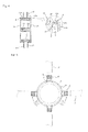
- Fig. 2 is a perspective view of a connector according to a first embodyment of the present invention.
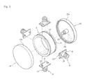
- Fig. 3 is an exploded view of the connector shown in Fig. 2 .
- Fig. 4 is a cross-sectional view of the connector taken from the line A-A in Fig. 2 .
- Fig. 5 is a front view of the connector shown in Fig. 2 .
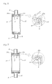
- Fig. 6 is a cross-sectional view of a connector according to a second embodyment of the present invention.
- Figs. 7 and 8 are cross-sectional views of the connectors according to a third and a forth embodyments of the present invention.
- Fig. 9 is a front view of the connector according to another embodyment of the present invention.
- the connectors of the present invention are used in same applications as the connector 1 shown in Fig. 1 .
- a plurality of linear members are radially connected to the central body of annular shape.
- At least one socket member is located between the central body and the linear member.
- One end of the socket member is connected to the central body and extends out radially, and the other end of the socket member is connected to the linear members such as pipes, wires and bars.
- the rail means is located at the connection between the central body and the socket member so that the socket member moves along the circumferential surface of the central body with one end of the socket member being connected to the central body.
- the rail means may be installed in various ways. As noted, the central body and the rail means can be modified within the scope of the present invention.
- a cylinder member 2 is used as the central body.
- Two L-shaped guide grooves 4 and latches 10 engaging the guide grooves are used as the rail means.
- the cylinder member 2 having a constant width includes two guide grooves 4 along the circumferential surface.
- the cylinder member 2 can be made as an unitary piece or made by two or more pieces. Referring to the Fig. 2 , the cylinder member 2 has a ring shape with a thickness of 1 to 4 cm, and two L-shaped guide grooves 4 are symmetrically provided on the cylinder member 2.
- a flange 8 Provided at one end of the socket member 6 is a flange 8. Latches 10 also are provided on the flange 8 such that the flange 8 can be moved along the guide grooves 4. Once the latches 10 engage with the guide grooves 4, the socket member 6 can not move away radially, but can rotate along the circumferential edges of the cylinder member 2.
- the flange 8 of the socket member 6 has a curved shape that corresponds to the curvature of the cylinder member 2.
- a slot 12 for inserting the latch 10 is provided on the surface of the cylinder member 2.
- the slot is preferably closed after the required numbers of the latches 10 are inserted.
- the slot 12 remains open, in this case, the socket member is preferably positioned at a distances from the slot.
- Linear members are connected to the other end of the socket member 6.
- a thread 13 is provided on the other end of the socket member 6.
- the linear member may comprise bar, wire, and pipe etc.
- linear members are shown as pipes P, and the linear members are referred to as pipes P below.
- the socket member 6 and the pipe P may be joined by threads.
- threads there is provided, for example, a male thread on the other end of the socket member 6 and a female thread on the inside of the pipe P.
- other connecting means such as rivets and welds can be employed.
- One or more socket members 6 can be mounted onto the cylinder member 2 and all of the socket members 6 need not to have a same shape. As shown in Fig. 9 , one of the socket members 6 can be connected to a post C of the wall structure. In this case, a bracket 11 can be provided at the other end of socket member 6.
- Cover members 14, 15 are fitted onto the opposite sides of the cylinder member 2. As shown in the drawings, the cover members 14, 15 can be fitted on by hooks. Specifically, rims 14a, 15a of the cover members 14, 15 are joined such that the the rims cover over the flanges 8 of the socket members 6 and conceal the guide grooves 4. Recesses 16 are provided on the flange 8 of the socket members and protrusions 20 are provided on the underside of the cover members 14, 15. The protrusions 20 engage with the recesses 16.
- Cover members 14, 15 are joined together by a center bolt 22 and a center nut 24 to prevent the cover members 14, 15 and the cylinder member 2 from disengaging.
- the center bolt 22 and the center nut 24 can be molded integrally with each of the cover members 14, 15.
- the cover members 14, 15 can be joined by hooks other than the bolt-nut joining means.
- the cover members 14, 15 may be engaged with the socket members 6 by threads.
- a male screw is provided on the top surface of the socket member 6 and a female screw is provided on the inside of the rims 14a, 15a of the cover members 14, 15.
- components, for example, the center bolt 22(see Fig. 4 ) of above embodyment are not needed any more.
- FIGs. 7 and 8 are cross-sectional views of the connectors according to the embodyments of the invention.
- the central body is the cylinder member 2 and cover members 14, 15 with rims on the edges thereof are fitted onto the opposite sides of the cylinder member 2.
- the rail means are formed by the circumferential surface of the cylinder member 2 and the rims 14a, 15a of the cover members.
- the circumferential surface is provided with two guide grooves 4 and two latches 10 formed at one end of the socket member 6 are engaged with the guide grooves 4.
- L-shaped guides are formed by assembling the cover members 14, 15 and the socket members 6.
- the socket members 6 can not moved away radially by the L-shaped guides formed between the cover members 14, 15 and the socket members 6.
- the cover members 14, 15 may be essential constitutions of the rail means in this embodyment.
- the cover members 14, 15 are engaged with each other by a center bolt 22 and a center nut 24.
- the cover members 14, 15 and the socket members 6 may be joined each other by threads. In this case, means for joining the cover members 14, 15 each other is not needed.
- cover members 14, 15 and the socket members 6 are snap-fitted by protrusions 20 and recesses 16 and the cover members 14, 15 are engaged with each other by a center bolt 22 and a center nut 24.
- Fig. 10 is a cross-sectional view of a connector according to yet another embodyment of the present invention.
- the cover members 14, 15 and the cylinder member 2 are joined together by threads.
- Guides formed by assembling the cover members 14, 15 and the socket members 6 are used as rail means.
- the guides prevent the socket members 6 from moving away from the cylinder member 2 radially.
- the central body is embodied as the cylinder member 2 and the cover members 14, 15 and the rail means are embodied as the guides that are formed by joining the cylinder member 2 and the cover members 14, 15.
- the cylinder members 2 are described and shown as a cylindrical shape, the present invention is not limited to this shape. Instead, the cylinder members 2 can have any shapes including an oval shape, or a polygon shape with round edges.
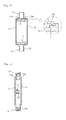
- Fig. 11 is a cross-sectional view of a connector according to yet another embodyment of the present invention and Fig. 12 is a exploded view of the connector shown in Fig. 11 .
- the cylinder members 2 see Figs. 2 to 10
- cover members 14, 15 are used as central body.
- the rail means are formed by the rims 14a, 15a of the cover members 14, 15 and a guide groove located around the socket member 6.
- the cover members 14, 15 are joined together by the center bolt 22 and the center nut 24.
- Connectors for linear members are assembled to a frame for a plastic greenhouse or a glasshouse by mounting the socket members 6 to the cylinder members 2, installing the cylinder members 2 to posts, screwing elongate pipes used as rafters to the socket members 6, and positioning the cylinder members 2 at vertices of a triangle such that the elongate pipes are sides of the triangle.
Applications Claiming Priority (1)
| Application Number | Priority Date | Filing Date | Title |
|---|---|---|---|
| KR1020080089624A KR100905921B1 (ko) | 2008-09-11 | 2008-09-11 | 경계 구조물의 선형부재 연결기구 |
Publications (2)
| Publication Number | Publication Date |
|---|---|
| EP2163704A2 true EP2163704A2 (de) | 2010-03-17 |
| EP2163704A3 EP2163704A3 (de) | 2012-08-29 |
Family
ID=41337213
Family Applications (1)
| Application Number | Title | Priority Date | Filing Date |
|---|---|---|---|
| EP09168940A Withdrawn EP2163704A3 (de) | 2008-09-11 | 2009-08-28 | Stecker für lineare Elemente |
Country Status (7)
| Country | Link |
|---|---|
| US (1) | US7972077B2 (de) |
| EP (1) | EP2163704A3 (de) |
| JP (1) | JP4856744B2 (de) |
| KR (1) | KR100905921B1 (de) |
| CN (1) | CN101672128B (de) |
| AU (1) | AU2009213061A1 (de) |
| CA (1) | CA2678431A1 (de) |
Families Citing this family (12)
| Publication number | Priority date | Publication date | Assignee | Title |
|---|---|---|---|---|
| KR101264079B1 (ko) | 2010-02-18 | 2013-05-14 | 김명수 | 선형부재 연결기구 |
| CN102011465B (zh) * | 2010-11-19 | 2012-07-04 | 湖南省金为型材有限公司 | 一种网状组装式护栏 |
| US9140466B2 (en) | 2012-07-17 | 2015-09-22 | Eemax, Inc. | Fluid heating system and instant fluid heating device |
| US10222091B2 (en) | 2012-07-17 | 2019-03-05 | Eemax, Inc. | Next generation modular heating system |
| US9234674B2 (en) * | 2012-12-21 | 2016-01-12 | Eemax, Inc. | Next generation bare wire water heater |
| CN107250686B (zh) | 2014-12-17 | 2020-03-17 | 伊麦克斯公司 | 无水箱式电热水器 |
| US10465396B2 (en) | 2015-10-06 | 2019-11-05 | Paul Kristen, Inc. | Platform with a track for attaching decking |
| DE102016010883A1 (de) | 2016-09-12 | 2018-03-29 | Technische Universität Chemnitz | Variables Verbindungselement |
| CN108179810A (zh) * | 2017-12-22 | 2018-06-19 | 山东经典重工集团股份有限公司 | 模块化的多高层装配式钢结构框架中心支撑体系 |
| USD846975S1 (en) * | 2018-02-22 | 2019-04-30 | Titan Ip, Llp | Pivot joint for expandable frame |
| IT201800020032A1 (it) * | 2018-12-18 | 2020-06-18 | Politecnico Di Bari | Giunto radiale multiplo |
| CN112376890B (zh) * | 2020-12-08 | 2021-12-10 | 湖南省秉谊建筑科技有限公司 | 一种高层建筑施工用外爬式施工防护平台 |
Citations (3)
| Publication number | Priority date | Publication date | Assignee | Title |
|---|---|---|---|---|
| US2212455A (en) * | 1938-10-18 | 1940-08-20 | Frank S Reed | Adjustable pipe railing fitting |
| DE4229406A1 (de) * | 1992-09-03 | 1994-03-10 | F & T Form & Technik | Knotenstück zur Verbindung von Streben eines Messe- oder Ladenbaugerüsts |
| KR20040079751A (ko) * | 2003-03-10 | 2004-09-16 | 김명수 | 가이드레일 파이프 연결구 |
Family Cites Families (15)
| Publication number | Priority date | Publication date | Assignee | Title |
|---|---|---|---|---|
| US1316155A (en) * | 1919-09-16 | Fitting | ||
| US1110183A (en) * | 1913-10-30 | 1914-09-08 | Harry J Bonham | Rail-fitting. |
| US1579159A (en) * | 1924-03-04 | 1926-03-30 | Spikings Albert Richard | Rail fitting |
| US2682235A (en) * | 1951-12-12 | 1954-06-29 | Fuller Richard Buckminster | Building construction |
| US3192669A (en) * | 1962-05-11 | 1965-07-06 | Super Sky Products Company | Skylight construction |
| JPS6099310A (ja) * | 1983-11-04 | 1985-06-03 | Agency Of Ind Science & Technol | 混合液体の分離方法 |
| JP2562375Y2 (ja) | 1992-09-22 | 1998-02-10 | ホリー株式会社 | 仮設パイプ用連結装置 |
| JP2001289211A (ja) * | 2000-04-05 | 2001-10-19 | Taiko:Kk | 棒材接続用自在接ぎ手 |
| KR20000064086A (ko) * | 2000-08-21 | 2000-11-06 | 송영구 | 관 연결용 허브부재 |
| US6698725B1 (en) * | 2000-09-14 | 2004-03-02 | Tracy L. Berry | Slotted fence post cap |
| JP4073356B2 (ja) * | 2003-04-11 | 2008-04-09 | 矢崎化工株式会社 | 縦型手摺りの設置構造 |
| WO2005028776A1 (en) * | 2003-09-19 | 2005-03-31 | A.C.N. 118 296 094 Pty Ltd | Handrail or top rail, post and panel assembly and connector therefor |
| CN2866928Y (zh) * | 2005-12-03 | 2007-02-07 | 李福德 | 一种组合架管件交汇连接单元 |
| FR2895431B1 (fr) * | 2005-12-23 | 2008-03-21 | Dirickx Groupe Sa | Dispositif de fixation d'une lisse sur un poteau |
| CN201092757Y (zh) * | 2007-09-05 | 2008-07-30 | 黄忠良 | 艺术围栏 |
-
2008
- 2008-09-11 KR KR1020080089624A patent/KR100905921B1/ko not_active IP Right Cessation
-
2009
- 2009-08-28 EP EP09168940A patent/EP2163704A3/de not_active Withdrawn
- 2009-08-31 JP JP2009200889A patent/JP4856744B2/ja not_active Expired - Fee Related
- 2009-09-02 CN CN2009101710651A patent/CN101672128B/zh not_active Expired - Fee Related
- 2009-09-10 US US12/557,059 patent/US7972077B2/en not_active Expired - Fee Related
- 2009-09-10 AU AU2009213061A patent/AU2009213061A1/en not_active Abandoned
- 2009-09-11 CA CA002678431A patent/CA2678431A1/en not_active Abandoned
Patent Citations (3)
| Publication number | Priority date | Publication date | Assignee | Title |
|---|---|---|---|---|
| US2212455A (en) * | 1938-10-18 | 1940-08-20 | Frank S Reed | Adjustable pipe railing fitting |
| DE4229406A1 (de) * | 1992-09-03 | 1994-03-10 | F & T Form & Technik | Knotenstück zur Verbindung von Streben eines Messe- oder Ladenbaugerüsts |
| KR20040079751A (ko) * | 2003-03-10 | 2004-09-16 | 김명수 | 가이드레일 파이프 연결구 |
Also Published As
| Publication number | Publication date |
|---|---|
| JP2010065524A (ja) | 2010-03-25 |
| EP2163704A3 (de) | 2012-08-29 |
| CN101672128B (zh) | 2012-03-21 |
| CN101672128A (zh) | 2010-03-17 |
| JP4856744B2 (ja) | 2012-01-18 |
| CA2678431A1 (en) | 2010-03-11 |
| US7972077B2 (en) | 2011-07-05 |
| US20100067978A1 (en) | 2010-03-18 |
| AU2009213061A1 (en) | 2010-03-25 |
| KR100905921B1 (ko) | 2009-07-02 |
Similar Documents
| Publication | Publication Date | Title |
|---|---|---|
| US7972077B2 (en) | Connector for linear members | |
| US6971831B2 (en) | Self-locking fastener | |
| US5452880A (en) | Fence coupling | |
| US9790689B2 (en) | Baluster connector | |
| US6698726B2 (en) | Rail clip | |
| US20150300041A1 (en) | Railing assembly with interference fit-based coupling | |
| EP2559831B1 (de) | Zaunpfahl und zaun | |
| WO2006118392A3 (en) | A falling rock preventing fence with fabrication typewire net | |
| CN102318155A (zh) | 一种用于安装线缆的槽道装置 | |
| US10410553B2 (en) | Method and apparatus for supporting a banner | |
| AU2013203633B2 (en) | A post mounting system and apparatus | |
| CA2901634A1 (en) | A post mounting system and apparatus | |
| US4553741A (en) | Plastic fence assembly | |
| EP1980688A1 (de) | Selbsttragender mehrteiliger Flügelzaunpfosten | |
| KR20130015926A (ko) | 평판형 원형 수로관 | |
| US20070158628A1 (en) | Fence | |
| MX2010000063A (es) | Conector para miembros lineales. | |
| KR101310006B1 (ko) | 펜스용 브라켓 및 상기 펜스용 브라켓을 구비한 펜스 | |
| KR101474720B1 (ko) | 데크용 가드레일포스트 | |
| KR20100117161A (ko) | 원통형 펜스의 시공시스템 | |
| JPH0448294Y2 (de) | ||
| KR200450978Y1 (ko) | 울타리의 결합 구조 | |
| ES2383693T3 (es) | Dispositivo para realizar la unión de dos cables entre sí, durante la fabricación de las mallas de una red de seguridad | |
| CN202450722U (zh) | 杆件连接结构及具有该杆件连接结构的栏杆或栅栏 | |
| KR200451673Y1 (ko) | 굴절가능한 펜스연결구 및 이를 이용한 펜스 |
Legal Events
| Date | Code | Title | Description |
|---|---|---|---|
| PUAI | Public reference made under article 153(3) epc to a published international application that has entered the european phase |
Free format text: ORIGINAL CODE: 0009012 |
|
| AK | Designated contracting states |
Kind code of ref document: A2 Designated state(s): AT BE BG CH CY CZ DE DK EE ES FI FR GB GR HR HU IE IS IT LI LT LU LV MC MK MT NL NO PL PT RO SE SI SK SM TR |
|
| PUAL | Search report despatched |
Free format text: ORIGINAL CODE: 0009013 |
|
| AK | Designated contracting states |
Kind code of ref document: A3 Designated state(s): AT BE BG CH CY CZ DE DK EE ES FI FR GB GR HR HU IE IS IT LI LT LU LV MC MK MT NL NO PL PT RO SE SI SK SM TR |
|
| AX | Request for extension of the european patent |
Extension state: AL BA RS |
|
| RIC1 | Information provided on ipc code assigned before grant |
Ipc: E04F 11/18 20060101AFI20120720BHEP |
|
| 17P | Request for examination filed |
Effective date: 20130118 |
|
| STAA | Information on the status of an ep patent application or granted ep patent |
Free format text: STATUS: THE APPLICATION HAS BEEN WITHDRAWN |
|
| 18W | Application withdrawn |
Effective date: 20130322 |