EP2162637B1 - Transmission par courroie en va-et-vient - Google Patents
Transmission par courroie en va-et-vient Download PDFInfo
- Publication number
- EP2162637B1 EP2162637B1 EP08756572A EP08756572A EP2162637B1 EP 2162637 B1 EP2162637 B1 EP 2162637B1 EP 08756572 A EP08756572 A EP 08756572A EP 08756572 A EP08756572 A EP 08756572A EP 2162637 B1 EP2162637 B1 EP 2162637B1
- Authority
- EP
- European Patent Office
- Prior art keywords
- drive
- belt
- pulley
- driven
- drive belt
- Prior art date
- Legal status (The legal status is an assumption and is not a legal conclusion. Google has not performed a legal analysis and makes no representation as to the accuracy of the status listed.)
- Not-in-force
Links
Images


Classifications
-
- B—PERFORMING OPERATIONS; TRANSPORTING
- B62—LAND VEHICLES FOR TRAVELLING OTHERWISE THAN ON RAILS
- B62K—CYCLES; CYCLE FRAMES; CYCLE STEERING DEVICES; RIDER-OPERATED TERMINAL CONTROLS SPECIALLY ADAPTED FOR CYCLES; CYCLE AXLE SUSPENSIONS; CYCLE SIDE-CARS, FORECARS, OR THE LIKE
- B62K3/00—Bicycles
- B62K3/002—Bicycles without a seat, i.e. the rider operating the vehicle in a standing position, e.g. non-motorized scooters; non-motorized scooters with skis or runners
-
- B—PERFORMING OPERATIONS; TRANSPORTING
- B62—LAND VEHICLES FOR TRAVELLING OTHERWISE THAN ON RAILS
- B62M—RIDER PROPULSION OF WHEELED VEHICLES OR SLEDGES; POWERED PROPULSION OF SLEDGES OR SINGLE-TRACK CYCLES; TRANSMISSIONS SPECIALLY ADAPTED FOR SUCH VEHICLES
- B62M1/00—Rider propulsion of wheeled vehicles
- B62M1/24—Rider propulsion of wheeled vehicles with reciprocating levers, e.g. foot levers
-
- F—MECHANICAL ENGINEERING; LIGHTING; HEATING; WEAPONS; BLASTING
- F16—ENGINEERING ELEMENTS AND UNITS; GENERAL MEASURES FOR PRODUCING AND MAINTAINING EFFECTIVE FUNCTIONING OF MACHINES OR INSTALLATIONS; THERMAL INSULATION IN GENERAL
- F16H—GEARING
- F16H31/00—Other gearings with freewheeling members or other intermittently driving members
-
- F—MECHANICAL ENGINEERING; LIGHTING; HEATING; WEAPONS; BLASTING
- F16—ENGINEERING ELEMENTS AND UNITS; GENERAL MEASURES FOR PRODUCING AND MAINTAINING EFFECTIVE FUNCTIONING OF MACHINES OR INSTALLATIONS; THERMAL INSULATION IN GENERAL
- F16H—GEARING
- F16H7/00—Gearings for conveying rotary motion by endless flexible members
- F16H7/02—Gearings for conveying rotary motion by endless flexible members with belts; with V-belts
- F16H7/023—Gearings for conveying rotary motion by endless flexible members with belts; with V-belts with belts having a toothed contact surface or regularly spaced bosses or hollows for slipless or nearly slipless meshing with complementary profiled contact surface of a pulley
Definitions
- Chain driven drive systems and other single speed torque transmission systems are well known and often utilized in many human powered applications.
- Known chain drive systems often include derailleur systems to provide for multiple chain and drive speeds.
- These known drive systems typically include multiple sprockets, one-way coaster axles and other hardware to couple with and control the torque transmitted via the drive chain. It would be desirable to provide a light and quiet drive system that may be utilized to transmit torque in, for example, a human powered application.
- EP 0 677 682 A1 on which the preamble of claim 1 is based relates to a transmission with fixed transmission ratio, wherein a flexible belt transfers forces from a driving pulley to a driven pulley.
- WO 2005/119087 A1 relates to a belt drive for an internal combustion engine.
- US 4,846,489 discloses a bicycle in which a toothed belt transfers the power from a driving gear to a driven gear.
- DE 101 19 495 A1 relates to a Citystepper in which reciprocating plates are coupled to a drive train via freewheel members.
- US 6,334,838 B1 discloses an exercising cart structure in which pedals are coupled to a drive train via transmission gears.
- US 4,411,442 discloses a foot powered wheeled vehicle in which pedals are connected to arclike pivotal connections driving pinion gears.
- a belt drive configured to cooperate with a drive mechanism.
- the belt drive may include a drive belt pulley reciprocally coupled to the drive mechanism wherein the drive mechanism reciprocally translates between a power stroke and a return stroke, a driven pulley reciprocally coupled to the drive belt pulley via a drive belt wherein the drive belt includes a plurality of asymmetrical drive teeth configured to cooperate with a plurality of asymmetrical driven teeth disposed on the driven pulley, and an engagement mechanism disposed substantially adjacent to the drive belt and the driven pulley wherein the engagement mechanism is configured to cooperate with the drive belt during the power stroke, and wherein the drive belt substantially disengages the driven pulley during the return stroke.
- a belt drive system may include a reciprocating drive mechanism having a drive belt pulley configured to provide a power stroke and a return stroke wherein the drive belt pulley includes a plurality asymmetric spoke teeth disposed about a circumference of the drive belt pulley, a driven pulley disposed away from the drive belt pulley wherein the driven pulley includes a plurality of asymmetrical driven teeth disposed thereon, and wherein each of the plurality of asymmetrical driven teeth includes a driven surface, a drive belt configured to releasably couple the drive belt pulley to the driven pulley as the drive mechanism reciprocates between the power stroke and the return stroke wherein the drive belt includes a plurality of asymmetrical drive teeth disposed thereon, and wherein each of the plurality of asymmetrical drive teeth includes a drive surface.
- the belt drive system may further include an engagement mechanism disposed substantially adjacent to the drive belt and the driven pulley wherein the engagement mechanism is configured to cooperate with
- a belt drive system may be disclosed.
- the belt drive system may include a drive belt pulley reciprocally coupled to a drive mechanism configured to translate between a power stroke and a return stroke, a drive belt fixedly coupled to the drive belt pulley, the drive belt including a plurality of asymmetrical drive teeth and wherein each of the plurality of asymmetrical drive teeth includes a drive surface arranged substantially perpendicular to a belt surface, and a driven pulley releasably coupled to the drive belt pulley via the drive belt, wherein the driven pulley includes a plurality of asymmetrical driven teeth and wherein each of the plurality of asymmetrical driven teeth may include a driven surface arranged to cooperate with the drive surface such that the drive belt cooperatively engages the driven pulley throughout the power stroke, and wherein the drive belt disengages from the driven pulley throughout the return stroke.
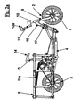
- FIG. 1 illustrates a perspective view of a version of a human powered scooter
- FIG. 2a illustrates a rear view of the version of FIG. 1 ;
- FIG. 2b illustrates a top view of the version of FIG. 1 ;
- FIG. 3a illustrates a mirrored isometric view of the version of FIG. 1 with the outer frame removed for clarity;
- FIG. 3b illustrates a rear view of the embodiment of FIG. 1 with the outer frame removed for clarity
- FIG. 3c illustrates an exploded rear portion of the version of FIG. 1 with the outer frame removed for clarity
- FIG. 4 illustrates a perspective view of the outer frame of the version of FIG. 1 ;
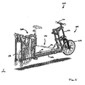
- FIG. 5 illustrates an embodiment of a human powered scooter utilizing a belt drive disclosed herein
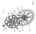
- FIG. 6 illustrates a perspective view of an embodiment of a belt drive coupled to a driven wheel
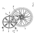
- FIG. 7 illustrates a plan view of an embodiment of the belt drive shown in FIG. 6 ;
- FIG. 8 Illustrates an enlarged plan view of an embodiment of the belt drive shown In FIG. 7 :
- FIG. 9 illustrates an embodiment of the belt drive shown throughout a power stroke
- FIG. 10 illustrates an embodiment of the belt drive shown throughout a return stroke and when coasting.
- the belt drive and belt drive system disclosed and discussed herein provides a light and robust reciprocating drive mechanism configured to propel a human powered device such as a scooter or a bicycle.
- a human powered device such as a scooter or a bicycle.
- various embodiments of the invention and a version of a human powered scooter are depicted, and reference is made herein to scooters and bicycles with the majority of the description being given in relation to scooters.
- the many aspects described in the in the various embodiments and said version may equally apply to stepping machines and other machines or vehicles and although those described are usually provided as two wheeled vehicles, other wheel or non-wheel arrangements may apply.
- the scooter 1 includes a front wheel assembly 2, a rear wheel assembly 3, an inner frame 4 and an outer frame 5. Unlike conventional scoters that rely solely on pushing of the vehicle by the user, this scooter also incorporates an embodiment of a drive mechanism 6 which is constructed to drive the rear wheel 7 and the use the front wheel 8 for steering.
- the front wheel assembly 2 includes a standard bicycle front wheel 7 mounted onto a front fork 9 in combination with a front braking attachment.
- the wheel 7 is connected to a steering column 10 having a handle bar 11 mounting right and left braking handles 12a and 12b.
- the invention also utilizes a pivoting head tube 16 and a steering column 10 along with a modified mounting plate 17, which is connected to the inner frame 4, for the optional pivoting and locking of one leg of the front fork 9 so that the front wheel 7 clears the ground sufficiently when moving the vehicle in a backward dolly mode.
- the outer frame 6 is also fitted with a seat post 13 and a seat 14 for optional seating arrangement at a specified position.
- the inner frame assembly 4 includes a series of strategically positioned standard mounting plates 19a and 19b, 20a and 20b, 21 a and 21b, 22a and 22b, and 24a and 24b. These plates are mounted together to provide a sturdy structural link between the front wheel assembly 2 through the modified mounting plate 17, and the rear wheel assembly 3 through the wheel mounting plate 26a & 26b.
- the treadle pivoting shaft 25 Is positioned In between the Joints of the mounting plates of 22a/22b and 24a/24b.
- the standard pedals 23a and 23b are pivotally mounted on each side of treadle pivoting shaft 25.
- the treadles 18a and 18b are mounted on these pedals 23a and 23b to generate the pivoting motion at the toe end.
- a central board 27 is placed over the top of the mounting plates 21 a & 21 b.
- the central board Incorporates a urethane bar 28 mounted across It using a mounting plate 29. This urethane bar acts as a stopper/cushioning pad for the treadles in the downward direction.
- a pair of small wheels 30a and 30b are positioned on each end at the joint of the mounting plates 19a/19b and 21a/21b.
- the plates 20a and 20b are mounted In between them. These are used for the protection of the inner frame assembly 4 over uneven ground or stairs.
- a tube gulding assembly 31 is attached in between the mounting plates 21 a and 21 b using standard "L" standoffs. This assembly guides the central tube attached to the outer frame 5 on which the seat post 13 Is mounted.
- a triangular shaped trimmed bicycle frame 32 is attached in between the mounting plates 19a & 19b, which supports and carries the front crankshaft 33.
- the pair of right and left treadles 18a and 18b are pivotally attached to the inner frame assembly 4 in the toe end on the treadle pivoting shaft 25, through standard right and left pedals 23a and 23b.
- the treadles 18a and 18b are connected to a pair of left and right common sprag-type one-way clutch devices known as Power Cranks. These are shown at 37a and 37b.
- the Power Cranks are attached via a pair of double swivel linkages 35a and 35b, and 36a and 35b, through hubs 34a and 34b mounted on the respective treadles.
- the front sprocket 39 is attached to one of the Power Cranks, for example the right Power Crank 37a.
- the pair of Power Cranks 37a and 37b assemblies are in turn mounted on a front crankshaft 33 which is held in position by a triangular shaped trimmed bicycle frame 32 attached to the inner frame assembly 4.
- the independent reciprocating motion of the treadles 18a and 18b is transmitted to the front crankshaft 33 as rotary motion through the Power Cranks 37a and 37b.
- This rotary motion in turn is transmitted to the front sprocket 39, which in turn transmits this rotary driving motion to the rear wheel 8 through a continuous chain 41 and a rear sprocket 40 mounted on the rear wheel 8.
- a second connection point may be added by attaching a pair of crank arms 38a & 38b perpendicularly to the respective Power Cranks 37a and 37b. This allows for the connection of a pair of springs 15a and 15b respectively which serves to automatically return the treadles 18a and 18b to a raised heel position when they are not weighted.
- the frame includes a plurality of horizontally placed aluminum tubes forming the bottom 42 and the top 43 parts of the frame.
- the frame also includes a set of vertically placed aluminum tubes forming the vertical part 46 and the rear part 45 of the frame, thereby connecting the bottom and top parts 42 and 43.
- a set of perpendicularly connected tubes 44 are attached to the middle tube of the top part 43 to form the locating position for the seat post 13.
- a pair of "Y"shaped tube connections 47a and 47b along with the front central tube 49 make up the front part of the outer frame assembly 6.
- the tubes 47a and 47b, and a set of cross tubes 48a and 48b support the modified mounting plate 17 supporting the pivoting head 16.
- the front central tube 49 supports a pair of small wheels 50a & 50b at each end which are used as a dolly for vehicle support when the front wheel is pivoted forward into a folded position for compact storage and movement.
- the rear tube of the bottom part 42 also supports a pair of small wheels 51a and 51b at each end which are used to assist the vehicle movement when the vehicle is standing vertically on its back end.
- the front wheel assembly can Incorporate standard bicycle components such as a bicycle front wheel mounted to a front fork with a front braking attachment, connected to a steering column with a handle bar containing front and back braking handles mounted on it.
- the rear wheel assembly can include a bicycle rear wheel mounted with a rear sprocket.
- the outer frame can comprise a series of aluminum pipes connected together using multiple pipe joints to form a skeleton frame to house the inner frame and to serve as attachment points for various extra equipment such carry-on and dolly pack.
- a series of aluminum pipes connected together using multiple pipe joints to form a skeleton frame to house the inner frame and to serve as attachment points for various extra equipment such carry-on and dolly pack.
- alternative materials and connection methods for the tubing or other structures may be used.
- the small wheels mounted on the frame allow for transportation In different positions.
- the return stroke of the pedals may be provided by a pair of springs connecting the perpendicular crank arms attached to the power cranks and the outer frame.
- the vehicle may include longer or multiple treadles along with larger frames to accommodate longer wheel base for multiple user or tandem use.
- the vehicle may also be fitted with battery power to assist the user by supplying partial driving force for exhausting tasks like moving uphill via an electronic regulator.
- the batteries in such a device may be charged during cruise and downhill situation
- the vehicle may also be fitted with a wireframe basket on top to carry loads or goods for street hawking or transporting; a canopy to provide shelter from sun and rain; or a wind shield pivotally on the same mounting shaft as the treadles to provide shelter from wind and rain during motion.
- a belt or harness may be provided to support flexible lines connected to the vehicle to allow the user to apply motive force to the treadles larger than the user's weight.
- this version of a scooter may be utilized with the above drive mechanism, variations, accessories or other drive arrangements which convert substantially rectilinear motions to circular motions of the cranks and the rear wheels.
- Such drive mechanisms will be discussed further below with respect to FIGS. 5 et seq.
- FIG. 5 illustrates a first embodiment of a human powered device 100.
- the human powered device 100 is configured as a scooter having a frame 102 supporting: a steering assembly 104; a reciprocating drive mechanism; and a belt drive 200 (see FIG. 6 ).
- the steering assembly 104 includes a steerable wheel 108 coupled to a handle bar 110 via a steering column 112.
- the reciprocating drive mechanism 108 includes a first drive pedal 114 and a second drive pedal 118 coupled to the belt drive 200.
- the belt drive 200 may, in turn, couple to and drive a driven wheel 118 to thereby propel the human powered device 100.
- FIGS. 6 and 7 illustrate perspective and plan views, respectively, of the belt drive 200 coupled to the driven wheel 118.
- the belt drive 200 includes a pair of drive belt pulleys 202, 202a coupled to a driven pulley 204, 204a of the driven wheel 118 via drive belts 208, 208a,
- the drive belts 206, 208a may be endless molded belts of thermo-set polyurethane and/or other elastomeric material configured to encase a reinforcing layer or portion of threads centered along the belt pitch line.
- the reinforcing threads may be Keviar® or any other aramid thread, steel wire or mesh and/or polyester threads.
- the drive belts 206, 206a may be manufactured via, for example, a spin casting or Centrifugal Rubber Mold Casting (CRMC) process that utilizes centrifugal force to produce castings from a rubber mold.
- Each of the drive belt pulleys 202, 202a includes a drive lever 208, 208a.
- the drive levers 208, 208a may be coupled to the first and second drive pedals 114, 116.
- the drive lever 208 may be coupled to the first drive pedal 114, and the drive lever 208a may be coupled to the second drive pedal 116.
- the physical position of the drive levers 208, 208a on the drive belt pulleys 202, 202a may be selected to ensure that each drive belt pulley 202, 202a rotates reciprocally with respect to the remaining drive belt pulley in response to the movement of the attached first and second drive pedals 114, 116.
- one drive belt pulleys 202 may rotate in a clockwise direction with respect to the other drive belt pulley 202a which may rotate in a counter-clockwise direction.
- the drive belt pulley 202a rotates in the direction indicated by the arrow A (see FIG. 6 ).
- the drive belt 206a releasably engages the driven pulley 204a and translates in the direction indicated by the arrow A' (see FIG. 6 ).
- the drive belt pulley 202 rotates in the direction indicated by the arrow B (see FIG. 7 ).
- the drive belt 206 disengages from the driven pulley 204 and translates in the direction indicated by the arrow B' (see FIG. 7 ).
- the drive belts 206, 206a may be fixedly and/or permanently secured to their respective drive belt pulleys 202, 202a such that only a portion of the belt may be utilized during each power or recovery stroke.
- the drive belts 206, 206a may be periodically adjusted to prevent excess wear at the point of cooperation with the driven pulley 204.
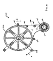
- FIG. 8 illustrates an enlarged plan view of the belt drive 200.
- half of the belt drive 200 including the drive belt pulley 202, the driven pulley 204 and the drive belt 206 are visible and illustrated in FIG. 8 .
- a plurality of idlers 400a to 400f may be positioned adjacent to the drive belt 206 to ensure adherence to the intended drive belt path.
- the drive belt pulley 202 may include a plurality of asymmetrical teeth 402 disposed or formed about the circumference. In one embodiment, the drive belt pulley 202 may have a diameter of 10.565" and a circumference of 33.1908".
- the driven pulley 204 may similarly include a plurality of asymmetrical teeth 404 disposed or formed about the circumference. In one embodiment, the driven pulley may have a diameter of 1.784" and a circumference of 5.6046".
- the drive belt pulley 202 may include one-hundred sixty-eight (168) of asymmetrical teeth 402 and the driven pulley 204 may include twenty-nine (29) of asymmetrical teeth 404 resulting in a drive ratio of 5.793 to 1.
- the length or pitch between each of the asymmetrical teeth 404 may be calculated to be 0.193" based on the exemplary measurements and sizes discussed and disclosed herein.
- FIG. 9 illustrates an enlarged plan view of the belt drive 200 during a power stroke of the drive mechanism 106 (see FIG. 5 ).
- the drive belt 206 includes a plurality of asymmetrical teeth 502 sized to engage, in a complementary and releasable manner, the asymmetrical teeth 402, 404 provided on the drive belt pulley 202 and driven pulley 204, respectively.
- Each of the asymmetrical teeth 502 of the drive belt 206 may have a 0.200" length or pitch that includes a ratchet surface 502b and a drive surface 502a height of 0.050".
- the difference in length or pitch (0.007) between the driven pulley 204 and the drive belt 206 may provide a complimentary fit between the distorted (due to bending) asymmetrical teeth 502 of the drive belt and the asymmetrical teeth 404 of the driven pulley 204.
- the drive surface 502a may be formed or manufactured at approximately a 100 degree included angle.
- the resulting asymmetrical teeth 502a may provide saw-tooth or ratchet-like structure suitable for engaging, driving and disengaging the driven pulley 204 as the drive sprocket 202 cycles between the power stroke and the return stroke.
- the driven pulley 204 may include the plurality of asymmetrical teeth 404 formed to compliment the asymmetrical teeth 502. Similar to the drive surface 502a, a drive surface 404a of the driven pulley 204 may be formed or manufactured at approximately a 100 degree included angle. Given the size, e.g., twenty-nine (29) teeth, of the driven pulley 204 relative to the size and configuration of the asymmetrical teeth 404, the 100 degree include angle at which the drive surface 404a is formed is substantially radial relative to the center of the driven pulley 204.
- This relative configuration between the asymmetrical teeth 404 and the asymmetrical teeth 504, ensures that the drive surfaces 404a and 502a ensure cooperate and/or mate during the power stroke of the drive belt pulley 202 and release from each other during the return stroke. Moreover, if, during operation, the driven pulley 204 is rotating too fast, for example, when the human powered device 100 is coasting downhill, the tooth configuration of driven pulley 204 ratchets the belt drive 206 away from the asymmetrical teeth 404 thereby preventing engagement and/or wear of the belt.
- An engagement mechanism 500 may be configured to releasably and controllably engage the drive belt 206 during a power stroke.
- the engagement mechanism may include a solenoid configured to shift an idler 500a into contact with the surface of the drive belt 206.
- the idler 500a brings the drive belt 206 into contact with the driven pulley 204.
- the idler 500a brings the drive surface 502a portion of the asymmetrical teeth 502 into contact with the drive surface 404a portion of the asymmetrical teeth 404.
- the engagement mechanism 500 may compel the drive belt 206 to cooperate with, and transmit torque to, to the driven pulley 204.
- the transmitted torque creates tension in the drive belt 206 which when cooperating with the engagement mechanism 500 causes the asymmetrical teeth 502 to engage and maintain engagement with the asymmetrical teeth 404 of the driven pulley.
- the engagement mechanism may be a cam driven mechanism, a spring driven mechanism and/or an electro-mechanical switch.
- alternate structures may be used to urge the belt towards the driven pulley, such as a finger or block slidable along a slot or track.
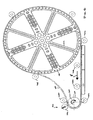
- FIG. 10 illustrates an enlarged plan view of the belt drive 200 during a return stroke of the drive mechanism 106 (see FIG. 5 ).
- FIG. 10 may also illustrated the belt drive in a coasting configuration.
- the coasting configuration may occur when the driven pulley 204 is rotating too quickly for the drive belt 206 to engage.
- the engagement mechanism 500 is disengaged, e.g., is in a retracted position, to allow the drive belt 206 to move substantially freely relatively to the driven pulley 204.
- the idler 500a releases the drive belt 206 from contact with the driven pulley 204.
- the drive belt 206 will, in one embodiment elastically deform or return to its disengagement radius or configuration.
- the drive belt 206 elastically returns to its original, e.g., pre-power stroke and engagement, shape, the drive surface 502a portion of the asymmetrical teeth 502 separates from the complimentary drive surface 404a portion of the asymmetrical teeth 404 of the driven pulley 204.
- the drive belt 206 may rotate and/or linearly translate relative to the driven pulley 204 without transmitting torque thereto.
- the idlers 400a to 400f ensure that the drive belt 206 remains substantially contained near the intended drive path, e.g., around the drive belt pulley 202 and the driven pulley 204.
- the drive belt pulley 202a and the drive belt 206a may be configured to operate in a reciprocal manner.
- the drive belt pulley 202a and the drive belt 206a are transmitting torque to the driven pulley 204 during the power stroke
- the drive belt pulley 202 and the drive belt 206 may be moving freely relative to the driven pulley 204 during a return stroke.
- the drive belt pulley 202a and the drive belt 206a may, upon completion of the power stroke, begin a return stroke while the drive belt pulley 202 and the drive belt 206 may begin a power stroke.
Landscapes
- Engineering & Computer Science (AREA)
- General Engineering & Computer Science (AREA)
- Mechanical Engineering (AREA)
- Chemical & Material Sciences (AREA)
- Combustion & Propulsion (AREA)
- Transportation (AREA)
- Devices For Conveying Motion By Means Of Endless Flexible Members (AREA)
- Transmission Devices (AREA)
- Transmissions By Endless Flexible Members (AREA)
- Valve Device For Special Equipments (AREA)
Claims (20)
- Transmission par courroie (200) configurée pour coopérer avec un mécanisme d'entraînement (106) effectuant une transition entre une course motrice et une course de retour, la transmission par courroie comprenant :une poulie à courroie d'entraînement (202, 202a) qui est configurée pour être reliée au mécanisme d'entraînement (106);une poulie menée (204, 204e) couplée à la poulie à courroie d'entraînement (202, 202a) par l'intermédiaire d'une courroie d'entraînement (206, 206a), dans laquelle la courroie d'entraînement (206, 206a) comporte plusieurs dents d'entraînement asymétriques (502) configurées pour coopérer avec plusieurs dents menées asymétriques (404) disposées sur la poulie menée (204, 204a) ; etun mécanisme de mise en prise (500) disposé de façon sensiblement adjacente à la courroie d'entraînement et à la poulie menée, dans lequel le mécanisme de mise en prise (500) est configuré pour coopérer avec la courroie d'entraînement (206, 206a) pour amorcer la course motrice, etcaractérisée en ce que la courroie d'entraînement (206, 206a) désengage sensiblement la poulie menée (204, 204a) pendant la course de retour.
- Transmission par courroie selon la revendication 1, dans laquelle la course de retour comporte une configuration à avance libre.
- Transmission par courroie selon la revendication 1 ou 2, dans laquelle la poulie à courroie d'entraînement (202, 202a) comprend plusieurs dents asymétriques à rayons (402) configurées pour coopérer avec les dents menées asymétriques (404).
- Transmission par courroie selon l'une des revendications précédentes, dans laquelle la poulie à courroie d'entraînement (202, 202a) et la poulie menée (204, 204a) sont dimensionnées pour définir approximativement un rapport d'entraînement de 5,8 à 1.
- Transmission par courroie selon l'une des revendications précédentes, dans laquelle la courroie d'entraînement (206, 206a) est une courroie d'entraînement en élastomère.
- Transmission par courroie selon la revendication 5, dans laquelle la courroie d'entraînement en élastomère comporte une partie de renfort sélectionnée à partir du groupe constitué par : des fibres d'aramide ; un fil d'acier ; et un fil de polyester.
- Transmission par courroie selon l'une des revendications précédentes, dans laquelle chacune des dents d'entraînement asymétriques (502) comporte une surface d'entraînement (502a) agencée de façon sensiblement perpendiculaire à la surface de la courroie d'entraînement (206, 206a), et dans laquelle chacune des dents menées (404) comporte une surface menée (404a) configurée pour mettre en prise une surface d'entraînement correspondante (502a).
- Transmission par courroie selon l'une des revendications précédentes, dans laquelle le mécanisme de mise en prise (500) est sélectionné à partir du groupe constitué par : un mécanisme entraîné par solénoïde, un commutateur électromécanique, et un mécanisme entraîné par came.
- Transmission par courroie selon la revendication 1, comprenant en outre :un mécanisme d'entraînement à va et vient (106), le mécanisme d'entraînement comportant la poulie à courroie d'entraînement (202, 202a) configurée pour fournir une course motrice et une course de retour, dans laquelle la poulie à courroie d'entraînement (202, 202a) comporte plusieurs dents asymétriques à rayons (402) disposées autour d'une circonférence de la poulie à courroie d'entraînement (202, 202a) ;dans laquelle la poulie menée (204, 204a) est disposée loin de la poulie à courroie d'entraînement (202, 202a), et dans laquelle chacune des dents menées asymétriques (404) de la poulie menée (204, 204a) comporte une surface menée (404a) ;une courroie d'entraînement (206, 206a), configurée pour coupler de façon amovible la poulie à courroie d'entraînement (202, 202a) à la poulie menée (204, 204a) en tant que mécanisme d'entraînement (106), effectue une transition entre la course motrice et la course de retour, dans laquelle la courroie d'entraînement (206, 206a) comporte lesdites dents d'entraînement asymétriques (502) disposées dessus, et dans laquelle chacune des dents d'entraînement asymétriques (502) comporte une surface d'entraînement (502a).
- Transmission par courroie selon la revendication 9, dans laquelle la course de retour comporte une configuration à avance libre.
- Transmission par courroie selon la revendication 9 ou 10, dans laquelle la poulie à courroie d'entraînement (202, 202a) est couplée de manière fixe à la courroie d'entraînement (206, 206a) dans au moins un emplacement simple.
- Transmission par courroie selon l'une des revendications 9 à 11, dans laquelle la poulie à courroie d'entraînement (202, 202a) et la poulie menée (204, 204a) sont dimensionnées pour définir approximativement un rapport d'entraînement de 5,8 à 1.
- Transmission par courroie selon l'une des revendications 9 à 12, dans laquelle la courroie d'entraînement (206, 206a) est une courroie d'entraînement en élastomère.
- Transmission par courroie selon la revendication 13, dans laquelle la courroie d'entraînement en élastomère comporte une partie de renfort sélectionnée à partir du groupe constitué par : des fibres d'aramide ; un fil d'acier ; et un fil de polyester.
- Transmission par courroie selon l'une des revendications 9 à 14, dans laquelle le mécanisme de mise en prise (500) est sélectionné à partir du groupe constitué par : un mécanisme entraîné par solénoïde, un commutateur électromécanique et un mécanisme entraîné par came.
- Transmission par courroie selon la revendication 1, dans laquelle la poulie à courroie d'entraînement (202, 202a) est configurée pour être couplée à un mécanisme d'entraînement (106) à va et vient;
la transmission par courroie comprenant en outre une courroie d'entraînement (206, 206a) couplée de manière fixe à la poulie à courroie d'entraînement (202, 202a), la courroie d'entraînement (206, 206a) comportant lesdites dents d'entraînement asymétriques (502) et dans laquelle chacune des dents d'entraînement asymétriques comporte une surface d'entraînement (502a) agencée de façon sensiblement perpendiculaire à une surface de courroie ; et
dans laquelle la poulie menée (204, 204a) est couplée de façon amovible à la poulie à courroie d'entraînement (202, 202a) par l'intermédiaire de la courroie d'entraînement (206, 206a), dans laquelle chacune des dents menées asymétriques (404) de la poulie menée (204, 204a) comporte une surface menée (404a) agencée pour coopérer avec la surface d'entraînement (502a) ;
dans laquelle la courroie d'entraînement (206, 206a) met en prise de façon coopérative la poulie menée (204, 204a) tout au long de la course motrice, et dans laquelle la courroie d'entraînement (206, 206a) se désengage de la poulie menée (204, 204a) tout au long de la course de retour. - Transmission par courroie selon la revendication 16, dans laquelle la course de retour comporte une configuration à avance libre.
- Transmission par courroie selon la revendication 16 ou 17, dans laquelle la poulie à courroie d'entraînement (202, 202a) et la poulie menée (204, 204a) sont dimensionnées pour définir approximativement un rapport d'entraînement de 5,8 à 1.
- Transmission par courroie selon l'une des revendications 16 à 18, dans laquelle la courroie d'entraînement (206, 206a) est une courroie d'entraînement en élastomère à plusieurs couches.
- Transmission par courroie selon la revendication 19, dans laquelle la courroie d'entraînement en élastomère comporte une partie de renfort sélectionnée à partir du groupe constitué par : des fibres d'aramide ; un fil d'acier ; et un fil de polyester.
Applications Claiming Priority (2)
| Application Number | Priority Date | Filing Date | Title |
|---|---|---|---|
| US93244407P | 2007-05-31 | 2007-05-31 | |
| PCT/US2008/065423 WO2008151084A2 (fr) | 2007-05-31 | 2008-05-30 | Transmission par courroie en va-et-vient |
Publications (3)
| Publication Number | Publication Date |
|---|---|
| EP2162637A2 EP2162637A2 (fr) | 2010-03-17 |
| EP2162637A4 EP2162637A4 (fr) | 2010-06-02 |
| EP2162637B1 true EP2162637B1 (fr) | 2012-01-11 |
Family
ID=40094381
Family Applications (1)
| Application Number | Title | Priority Date | Filing Date |
|---|---|---|---|
| EP08756572A Not-in-force EP2162637B1 (fr) | 2007-05-31 | 2008-05-30 | Transmission par courroie en va-et-vient |
Country Status (5)
| Country | Link |
|---|---|
| US (1) | US20090023527A1 (fr) |
| EP (1) | EP2162637B1 (fr) |
| CN (1) | CN101772659A (fr) |
| AT (1) | ATE541144T1 (fr) |
| WO (1) | WO2008151084A2 (fr) |
Families Citing this family (1)
| Publication number | Priority date | Publication date | Assignee | Title |
|---|---|---|---|---|
| US9783261B2 (en) * | 2014-09-21 | 2017-10-10 | Efim GIMPEL | Demountable device for transformation of treadle lever rocking movement into rotary movement of bicycle#S drive shaft |
Family Cites Families (59)
| Publication number | Priority date | Publication date | Assignee | Title |
|---|---|---|---|---|
| US539613A (en) * | 1895-05-21 | George | ||
| US2654263A (en) * | 1953-01-02 | 1953-10-06 | Lloyd H Pringnitz | Clutch and throttle control for balers |
| US3375023A (en) * | 1965-11-12 | 1968-03-26 | James W. Cox | Velocipede driving apparatus |
| US3583250A (en) * | 1969-04-01 | 1971-06-08 | Rca Corp | Transmission including toothed belt and partially toothed pulley |
| US3913945A (en) * | 1974-05-01 | 1975-10-21 | Marion A Clark | Bicycle with variable speed lever action drive |
| US4186934A (en) * | 1978-09-27 | 1980-02-05 | Collings Thomas J | Scooter vehicle |
| US4449959A (en) * | 1980-10-10 | 1984-05-22 | Mitsuboshi Belting Ltd. | Cross grooved banded drive belt |
| US4379566A (en) * | 1981-01-26 | 1983-04-12 | Creative Motion Industries, Inc. | Operator powered vehicle |
| US4411442A (en) * | 1981-08-17 | 1983-10-25 | Rills Nolan J | Foot-powered wheeled vehicle |
| US4574649A (en) * | 1982-03-10 | 1986-03-11 | B. D. Yim | Propulsion and speed change mechanism for lever propelled bicycles |
| US4846489A (en) * | 1985-12-31 | 1989-07-11 | Ernest Kleinebenne | Pedal-driven vehicle |
| US4761014A (en) * | 1987-04-28 | 1988-08-02 | Huang Kung Hsiung | Propulsion of scooters |
| US4828284A (en) * | 1987-06-01 | 1989-05-09 | Sandgren John A | Treadle cycle |
| US4857035A (en) * | 1988-07-21 | 1989-08-15 | Anderson Cyril F | Continuous, variable power bicycle transmission device |
| US5294140A (en) * | 1990-05-25 | 1994-03-15 | Isaac Rinkewich | Self-propelled vehicle |
| US5061224A (en) * | 1990-08-20 | 1991-10-29 | Stuhler William B | Variable speed bicycle automatic torque converter transmission |
| US5110148A (en) * | 1990-12-14 | 1992-05-05 | Champion Toy Company | Three-wheeled scooter with reciprocating treadle drive |
| US5238462A (en) * | 1991-02-20 | 1993-08-24 | Life Fitness | Stair climbing exercise apparatus utilizing drive belts |
| US5163696A (en) * | 1991-10-04 | 1992-11-17 | Pesco Sr Roger J | Scooter apparatus |
| US5201688A (en) * | 1991-10-31 | 1993-04-13 | General Motors Corporation | Torque transmission system for connecting parallel shafts |
| US5772546A (en) * | 1993-06-29 | 1998-06-30 | Warszewski; Jaroslaw Piotr | Continuously variable automatic drive |
| NL9400586A (nl) * | 1994-04-13 | 1995-11-01 | Doornes Transmissie Bv | Overbrenging met vaste overbrengingsverhouding. |
| US5520401A (en) * | 1994-09-01 | 1996-05-28 | Mohseni; Abbas Z. | Step drive cycle |
| US5775708A (en) * | 1995-10-02 | 1998-07-07 | Heath; Steven C. | Exercise vehicle with cable steering system |
| US5895065A (en) * | 1996-02-29 | 1999-04-20 | Khomo; Malome T. | Method and means of enhancing human powered locomotion |
| TW338967U (en) * | 1997-02-19 | 1998-08-21 | song-mao Cai | Improved structure of a self-driven system |
| US6131933A (en) * | 1998-06-18 | 2000-10-17 | Fan; Ronnie Chee Keung | Drive mechanism for vehicle |
| US6241269B1 (en) * | 1998-12-21 | 2001-06-05 | Ronnie Chee Keung Fan | Drive mechanism for vehicle |
| US6402651B1 (en) * | 1999-09-14 | 2002-06-11 | Chester Lee Shirley | Emergency drive belt |
| US6270102B1 (en) * | 1999-10-18 | 2001-08-07 | Ronnie Chee Keung Fan | Drive mechanism for scooter |
| ES2244645T3 (es) * | 2000-08-18 | 2005-12-16 | The Gates Corporation | Correa de transmision de potencia provista de un elemento de caucho adhesivo de alto modulo. |
| US6398244B1 (en) * | 2000-09-27 | 2002-06-04 | Vigorousport Int., Co., Ltd. | Propelling scooter |
| US6419251B1 (en) * | 2000-09-27 | 2002-07-16 | Hung-Che Chueh | Propelling scooter |
| US6334838B1 (en) * | 2000-11-03 | 2002-01-01 | James Lee | Exercising cart structure |
| US6773022B2 (en) * | 2000-11-15 | 2004-08-10 | Dean R. Janssen | Step-cycle for exercise, recreation, and transport having telescopically movable pedals |
| TW498035B (en) * | 2001-01-15 | 2002-08-11 | Jui-Kuang Chen | Pedaling car |
| KR200251543Y1 (ko) * | 2001-03-08 | 2001-11-16 | 전홍수 | 자전거의 동력구동장치 |
| US6439590B1 (en) * | 2001-03-13 | 2002-08-27 | Fa-Kuang Liang | Standing-pedaling bike |
| DE10119495A1 (de) * | 2001-04-20 | 2002-11-14 | Rolf Guenther | Citystepper |
| US6572128B2 (en) * | 2001-04-29 | 2003-06-03 | Horst Graf | Ratchet propulsion system for scooters |
| US6688624B2 (en) * | 2001-05-01 | 2004-02-10 | Gcp, Llc | Foot pump scooter |
| US20030098566A1 (en) * | 2001-05-01 | 2003-05-29 | Christensen Donald J. | Lever operated foot pump scooter |
| US6716141B2 (en) * | 2001-05-16 | 2004-04-06 | Suresh Babu M. Bhoopathy | Mechanically actuated scooter |
| AUPR561101A0 (en) * | 2001-06-12 | 2001-07-12 | Sunbeam Corporation Limited | Food mixer |
| US20020195787A1 (en) * | 2001-06-25 | 2002-12-26 | Tuch Manfred W. | Childs ride-on treadle scooter |
| US6557880B2 (en) * | 2001-06-27 | 2003-05-06 | Walter Brooks Drew | Multiwheel self propelled variable output vehicle |
| US6659486B2 (en) * | 2001-07-02 | 2003-12-09 | Paul William Eschenbach | Exercise scooter |
| US6715779B2 (en) * | 2001-07-02 | 2004-04-06 | Paul William Eschenbach | Exercise scooter with stunt features |
| CA2414580A1 (fr) * | 2001-12-19 | 2003-06-19 | Johnny Chow | Trottinette a pedales |
| US20030127822A1 (en) * | 2002-01-08 | 2003-07-10 | Fleck Steven James | Transportation device |
| HK1050108A2 (en) * | 2002-04-11 | 2003-05-16 | Hon-Cheung George Hung | Pedalling machines including scooters and driving mechanisms therefor |
| GB2387360B (en) * | 2002-04-12 | 2005-06-01 | Tuncer Mehmet | Pedal scooter |
| US20040036249A1 (en) * | 2002-06-01 | 2004-02-26 | Mcguire Mark J. | Pedal driven scooter |
| NO317715B1 (no) * | 2002-11-21 | 2004-12-06 | Opsvik Peter As | Personlig transportenhet |
| ITMI20022702A1 (it) * | 2002-12-20 | 2004-06-21 | Giovanni Battista Bauce | Veicolo ed in particolare monopattino |
| US6949211B2 (en) * | 2003-04-16 | 2005-09-27 | The Goodyear & Rubber Company | Means of manufacturing plural optimized cogged drive belts |
| US6796570B1 (en) * | 2003-11-18 | 2004-09-28 | Hung-Shen Chang | Foot-tread type scooter |
| BRPI0511790A (pt) * | 2004-06-03 | 2008-01-15 | Schaeffler Kg | mecanismo de tração de custo otimizado |
| US7468022B1 (en) * | 2008-03-19 | 2008-12-23 | Hexon Enterprise Co., Ltd. | Bidirectional single linkage damping mechanism for leg exerciser |
-
2008
- 2008-05-30 EP EP08756572A patent/EP2162637B1/fr not_active Not-in-force
- 2008-05-30 US US12/130,897 patent/US20090023527A1/en not_active Abandoned
- 2008-05-30 WO PCT/US2008/065423 patent/WO2008151084A2/fr active Application Filing
- 2008-05-30 AT AT08756572T patent/ATE541144T1/de active
- 2008-05-30 CN CN200880101498A patent/CN101772659A/zh active Pending
Also Published As
| Publication number | Publication date |
|---|---|
| US20090023527A1 (en) | 2009-01-22 |
| EP2162637A2 (fr) | 2010-03-17 |
| WO2008151084A3 (fr) | 2009-02-05 |
| EP2162637A4 (fr) | 2010-06-02 |
| ATE541144T1 (de) | 2012-01-15 |
| WO2008151084A2 (fr) | 2008-12-11 |
| CN101772659A (zh) | 2010-07-07 |
Similar Documents
| Publication | Publication Date | Title |
|---|---|---|
| US6688624B2 (en) | Foot pump scooter | |
| CA2670278C (fr) | Vehicule autopropulse, propulse par un groupe motopropulseur elliptique | |
| US6572128B2 (en) | Ratchet propulsion system for scooters | |
| US8128111B2 (en) | Scooter and pedal drive assembly | |
| US6000707A (en) | Linear driving apparatus | |
| US4928986A (en) | Arm and leg powered cycle | |
| US8517405B2 (en) | Human powered vehicle with two reciprocal pedals | |
| US6619682B2 (en) | Scooter | |
| US5653663A (en) | Arm and leg powered cycle and method of use thereof | |
| US20050051992A1 (en) | Bicycle drive mechanism | |
| WO1999019202A1 (fr) | Appareil de propulsion lineaire | |
| CN108025795B (zh) | 骑行者驱动车辆及其机构 | |
| EP2162637B1 (fr) | Transmission par courroie en va-et-vient | |
| CN201165298Y (zh) | 踏板车 | |
| CN102826157A (zh) | 一种自行车高效驱动机构 | |
| US11891152B2 (en) | Human-powered vehicle | |
| KR102091022B1 (ko) | 스텝 구동식 사륜 자전거 | |
| CN201296347Y (zh) | 人力车用动力传动装置及自行车和滑板车 | |
| SU1221025A1 (ru) | Транспортное средство | |
| WO2000056595A1 (fr) | Organe d'entrainement a double propulsion pour vehicule a propulsion humaine | |
| CN102837792A (zh) | 自行车高效驱动机构 | |
| WO2007001126A1 (fr) | Patinette avec fonction de commande de vitesse | |
| KR20090132569A (ko) | 스테핑 운동용 자전거 |
Legal Events
| Date | Code | Title | Description |
|---|---|---|---|
| PUAI | Public reference made under article 153(3) epc to a published international application that has entered the european phase |
Free format text: ORIGINAL CODE: 0009012 |
|
| 17P | Request for examination filed |
Effective date: 20091223 |
|
| AK | Designated contracting states |
Kind code of ref document: A2 Designated state(s): AT BE BG CH CY CZ DE DK EE ES FI FR GB GR HR HU IE IS IT LI LT LU LV MC MT NL NO PL PT RO SE SI SK TR |
|
| AX | Request for extension of the european patent |
Extension state: AL BA MK RS |
|
| A4 | Supplementary search report drawn up and despatched |
Effective date: 20100507 |
|
| RIC1 | Information provided on ipc code assigned before grant |
Ipc: F16G 5/20 20060101ALI20100429BHEP Ipc: B62M 9/00 20060101ALI20100429BHEP Ipc: B62M 9/06 20060101ALI20100429BHEP Ipc: F16H 7/06 20060101AFI20081230BHEP Ipc: F16H 7/02 20060101ALI20100429BHEP Ipc: F16G 1/28 20060101ALI20100429BHEP |
|
| RIC1 | Information provided on ipc code assigned before grant |
Ipc: F16H 7/06 20060101AFI20110224BHEP Ipc: F16G 1/28 20060101ALI20110224BHEP Ipc: F16H 7/02 20060101ALI20110224BHEP Ipc: B62M 9/00 20060101ALI20110224BHEP Ipc: F16G 5/20 20060101ALI20110224BHEP Ipc: B62M 9/06 20060101ALI20110224BHEP |
|
| GRAP | Despatch of communication of intention to grant a patent |
Free format text: ORIGINAL CODE: EPIDOSNIGR1 |
|
| DAX | Request for extension of the european patent (deleted) | ||
| GRAS | Grant fee paid |
Free format text: ORIGINAL CODE: EPIDOSNIGR3 |
|
| GRAA | (expected) grant |
Free format text: ORIGINAL CODE: 0009210 |
|
| AK | Designated contracting states |
Kind code of ref document: B1 Designated state(s): AT BE BG CH CY CZ DE DK EE ES FI FR GB GR HR HU IE IS IT LI LT LU LV MC MT NL NO PL PT RO SE SI SK TR |
|
| REG | Reference to a national code |
Ref country code: GB Ref legal event code: FG4D |
|
| REG | Reference to a national code |
Ref country code: CH Ref legal event code: EP |
|
| REG | Reference to a national code |
Ref country code: AT Ref legal event code: REF Ref document number: 541144 Country of ref document: AT Kind code of ref document: T Effective date: 20120115 |
|
| REG | Reference to a national code |
Ref country code: IE Ref legal event code: FG4D |
|
| REG | Reference to a national code |
Ref country code: DE Ref legal event code: R096 Ref document number: 602008012689 Country of ref document: DE Effective date: 20120315 |
|
| REG | Reference to a national code |
Ref country code: NL Ref legal event code: VDEP Effective date: 20120111 |
|
| PG25 | Lapsed in a contracting state [announced via postgrant information from national office to epo] |
Ref country code: SI Free format text: LAPSE BECAUSE OF FAILURE TO SUBMIT A TRANSLATION OF THE DESCRIPTION OR TO PAY THE FEE WITHIN THE PRESCRIBED TIME-LIMIT Effective date: 20120111 |
|
| LTIE | Lt: invalidation of european patent or patent extension |
Effective date: 20120111 |
|
| PG25 | Lapsed in a contracting state [announced via postgrant information from national office to epo] |
Ref country code: BE Free format text: LAPSE BECAUSE OF FAILURE TO SUBMIT A TRANSLATION OF THE DESCRIPTION OR TO PAY THE FEE WITHIN THE PRESCRIBED TIME-LIMIT Effective date: 20120111 Ref country code: BG Free format text: LAPSE BECAUSE OF FAILURE TO SUBMIT A TRANSLATION OF THE DESCRIPTION OR TO PAY THE FEE WITHIN THE PRESCRIBED TIME-LIMIT Effective date: 20120411 Ref country code: NO Free format text: LAPSE BECAUSE OF FAILURE TO SUBMIT A TRANSLATION OF THE DESCRIPTION OR TO PAY THE FEE WITHIN THE PRESCRIBED TIME-LIMIT Effective date: 20120411 Ref country code: NL Free format text: LAPSE BECAUSE OF FAILURE TO SUBMIT A TRANSLATION OF THE DESCRIPTION OR TO PAY THE FEE WITHIN THE PRESCRIBED TIME-LIMIT Effective date: 20120111 Ref country code: HR Free format text: LAPSE BECAUSE OF FAILURE TO SUBMIT A TRANSLATION OF THE DESCRIPTION OR TO PAY THE FEE WITHIN THE PRESCRIBED TIME-LIMIT Effective date: 20120111 Ref country code: IS Free format text: LAPSE BECAUSE OF FAILURE TO SUBMIT A TRANSLATION OF THE DESCRIPTION OR TO PAY THE FEE WITHIN THE PRESCRIBED TIME-LIMIT Effective date: 20120511 Ref country code: LT Free format text: LAPSE BECAUSE OF FAILURE TO SUBMIT A TRANSLATION OF THE DESCRIPTION OR TO PAY THE FEE WITHIN THE PRESCRIBED TIME-LIMIT Effective date: 20120111 |
|
| PG25 | Lapsed in a contracting state [announced via postgrant information from national office to epo] |
Ref country code: PT Free format text: LAPSE BECAUSE OF FAILURE TO SUBMIT A TRANSLATION OF THE DESCRIPTION OR TO PAY THE FEE WITHIN THE PRESCRIBED TIME-LIMIT Effective date: 20120511 Ref country code: PL Free format text: LAPSE BECAUSE OF FAILURE TO SUBMIT A TRANSLATION OF THE DESCRIPTION OR TO PAY THE FEE WITHIN THE PRESCRIBED TIME-LIMIT Effective date: 20120111 Ref country code: FI Free format text: LAPSE BECAUSE OF FAILURE TO SUBMIT A TRANSLATION OF THE DESCRIPTION OR TO PAY THE FEE WITHIN THE PRESCRIBED TIME-LIMIT Effective date: 20120111 Ref country code: GR Free format text: LAPSE BECAUSE OF FAILURE TO SUBMIT A TRANSLATION OF THE DESCRIPTION OR TO PAY THE FEE WITHIN THE PRESCRIBED TIME-LIMIT Effective date: 20120412 Ref country code: LV Free format text: LAPSE BECAUSE OF FAILURE TO SUBMIT A TRANSLATION OF THE DESCRIPTION OR TO PAY THE FEE WITHIN THE PRESCRIBED TIME-LIMIT Effective date: 20120111 |
|
| REG | Reference to a national code |
Ref country code: AT Ref legal event code: MK05 Ref document number: 541144 Country of ref document: AT Kind code of ref document: T Effective date: 20120111 |
|
| PG25 | Lapsed in a contracting state [announced via postgrant information from national office to epo] |
Ref country code: CY Free format text: LAPSE BECAUSE OF FAILURE TO SUBMIT A TRANSLATION OF THE DESCRIPTION OR TO PAY THE FEE WITHIN THE PRESCRIBED TIME-LIMIT Effective date: 20120111 |
|
| PG25 | Lapsed in a contracting state [announced via postgrant information from national office to epo] |
Ref country code: RO Free format text: LAPSE BECAUSE OF FAILURE TO SUBMIT A TRANSLATION OF THE DESCRIPTION OR TO PAY THE FEE WITHIN THE PRESCRIBED TIME-LIMIT Effective date: 20120111 Ref country code: EE Free format text: LAPSE BECAUSE OF FAILURE TO SUBMIT A TRANSLATION OF THE DESCRIPTION OR TO PAY THE FEE WITHIN THE PRESCRIBED TIME-LIMIT Effective date: 20120111 Ref country code: SE Free format text: LAPSE BECAUSE OF FAILURE TO SUBMIT A TRANSLATION OF THE DESCRIPTION OR TO PAY THE FEE WITHIN THE PRESCRIBED TIME-LIMIT Effective date: 20120111 Ref country code: DK Free format text: LAPSE BECAUSE OF FAILURE TO SUBMIT A TRANSLATION OF THE DESCRIPTION OR TO PAY THE FEE WITHIN THE PRESCRIBED TIME-LIMIT Effective date: 20120111 Ref country code: CZ Free format text: LAPSE BECAUSE OF FAILURE TO SUBMIT A TRANSLATION OF THE DESCRIPTION OR TO PAY THE FEE WITHIN THE PRESCRIBED TIME-LIMIT Effective date: 20120111 |
|
| PLBE | No opposition filed within time limit |
Free format text: ORIGINAL CODE: 0009261 |
|
| STAA | Information on the status of an ep patent application or granted ep patent |
Free format text: STATUS: NO OPPOSITION FILED WITHIN TIME LIMIT |
|
| PG25 | Lapsed in a contracting state [announced via postgrant information from national office to epo] |
Ref country code: IT Free format text: LAPSE BECAUSE OF FAILURE TO SUBMIT A TRANSLATION OF THE DESCRIPTION OR TO PAY THE FEE WITHIN THE PRESCRIBED TIME-LIMIT Effective date: 20120111 Ref country code: SK Free format text: LAPSE BECAUSE OF FAILURE TO SUBMIT A TRANSLATION OF THE DESCRIPTION OR TO PAY THE FEE WITHIN THE PRESCRIBED TIME-LIMIT Effective date: 20120111 |
|
| 26N | No opposition filed |
Effective date: 20121012 |
|
| PG25 | Lapsed in a contracting state [announced via postgrant information from national office to epo] |
Ref country code: MC Free format text: LAPSE BECAUSE OF NON-PAYMENT OF DUE FEES Effective date: 20120531 |
|
| REG | Reference to a national code |
Ref country code: CH Ref legal event code: PL |
|
| GBPC | Gb: european patent ceased through non-payment of renewal fee |
Effective date: 20120530 |
|
| PG25 | Lapsed in a contracting state [announced via postgrant information from national office to epo] |
Ref country code: LI Free format text: LAPSE BECAUSE OF NON-PAYMENT OF DUE FEES Effective date: 20120531 Ref country code: AT Free format text: LAPSE BECAUSE OF FAILURE TO SUBMIT A TRANSLATION OF THE DESCRIPTION OR TO PAY THE FEE WITHIN THE PRESCRIBED TIME-LIMIT Effective date: 20120111 Ref country code: CH Free format text: LAPSE BECAUSE OF NON-PAYMENT OF DUE FEES Effective date: 20120531 |
|
| REG | Reference to a national code |
Ref country code: DE Ref legal event code: R097 Ref document number: 602008012689 Country of ref document: DE Effective date: 20121012 |
|
| REG | Reference to a national code |
Ref country code: IE Ref legal event code: MM4A |
|
| REG | Reference to a national code |
Ref country code: FR Ref legal event code: ST Effective date: 20130131 |
|
| REG | Reference to a national code |
Ref country code: DE Ref legal event code: R119 Ref document number: 602008012689 Country of ref document: DE Effective date: 20121201 |
|
| PG25 | Lapsed in a contracting state [announced via postgrant information from national office to epo] |
Ref country code: FR Free format text: LAPSE BECAUSE OF NON-PAYMENT OF DUE FEES Effective date: 20120531 Ref country code: GB Free format text: LAPSE BECAUSE OF NON-PAYMENT OF DUE FEES Effective date: 20120530 Ref country code: IE Free format text: LAPSE BECAUSE OF NON-PAYMENT OF DUE FEES Effective date: 20120530 |
|
| PG25 | Lapsed in a contracting state [announced via postgrant information from national office to epo] |
Ref country code: DE Free format text: LAPSE BECAUSE OF NON-PAYMENT OF DUE FEES Effective date: 20121201 |
|
| PG25 | Lapsed in a contracting state [announced via postgrant information from national office to epo] |
Ref country code: MT Free format text: LAPSE BECAUSE OF FAILURE TO SUBMIT A TRANSLATION OF THE DESCRIPTION OR TO PAY THE FEE WITHIN THE PRESCRIBED TIME-LIMIT Effective date: 20120111 |
|
| PG25 | Lapsed in a contracting state [announced via postgrant information from national office to epo] |
Ref country code: ES Free format text: LAPSE BECAUSE OF FAILURE TO SUBMIT A TRANSLATION OF THE DESCRIPTION OR TO PAY THE FEE WITHIN THE PRESCRIBED TIME-LIMIT Effective date: 20120422 |
|
| PG25 | Lapsed in a contracting state [announced via postgrant information from national office to epo] |
Ref country code: TR Free format text: LAPSE BECAUSE OF FAILURE TO SUBMIT A TRANSLATION OF THE DESCRIPTION OR TO PAY THE FEE WITHIN THE PRESCRIBED TIME-LIMIT Effective date: 20120111 |
|
| PG25 | Lapsed in a contracting state [announced via postgrant information from national office to epo] |
Ref country code: LU Free format text: LAPSE BECAUSE OF NON-PAYMENT OF DUE FEES Effective date: 20120530 |
|
| PG25 | Lapsed in a contracting state [announced via postgrant information from national office to epo] |
Ref country code: HU Free format text: LAPSE BECAUSE OF FAILURE TO SUBMIT A TRANSLATION OF THE DESCRIPTION OR TO PAY THE FEE WITHIN THE PRESCRIBED TIME-LIMIT Effective date: 20080530 |