EP2162086B1 - Herstellung einer nicht abgebildeten ansicht eines objekts mithilfe erfasster bilder - Google Patents
Herstellung einer nicht abgebildeten ansicht eines objekts mithilfe erfasster bilder Download PDFInfo
- Publication number
- EP2162086B1 EP2162086B1 EP08800409.8A EP08800409A EP2162086B1 EP 2162086 B1 EP2162086 B1 EP 2162086B1 EP 08800409 A EP08800409 A EP 08800409A EP 2162086 B1 EP2162086 B1 EP 2162086B1
- Authority
- EP
- European Patent Office
- Prior art keywords
- plane view
- plane
- vertebra
- view
- imaged
- Prior art date
- Legal status (The legal status is an assumption and is not a legal conclusion. Google has not performed a legal analysis and makes no representation as to the accuracy of the status listed.)
- Not-in-force
Links
Images




Classifications
-
- A—HUMAN NECESSITIES
- A61—MEDICAL OR VETERINARY SCIENCE; HYGIENE
- A61B—DIAGNOSIS; SURGERY; IDENTIFICATION
- A61B5/00—Measuring for diagnostic purposes; Identification of persons
- A61B5/103—Measuring devices for testing the shape, pattern, colour, size or movement of the body or parts thereof, for diagnostic purposes
- A61B5/107—Measuring physical dimensions, e.g. size of the entire body or parts thereof
- A61B5/1075—Measuring physical dimensions, e.g. size of the entire body or parts thereof for measuring dimensions by non-invasive methods, e.g. for determining thickness of tissue layer
-
- A—HUMAN NECESSITIES
- A61—MEDICAL OR VETERINARY SCIENCE; HYGIENE
- A61B—DIAGNOSIS; SURGERY; IDENTIFICATION
- A61B34/00—Computer-aided surgery; Manipulators or robots specially adapted for use in surgery
- A61B34/20—Surgical navigation systems; Devices for tracking or guiding surgical instruments, e.g. for frameless stereotaxis
-
- A—HUMAN NECESSITIES
- A61—MEDICAL OR VETERINARY SCIENCE; HYGIENE
- A61B—DIAGNOSIS; SURGERY; IDENTIFICATION
- A61B6/00—Apparatus or devices for radiation diagnosis; Apparatus or devices for radiation diagnosis combined with radiation therapy equipment
- A61B6/46—Arrangements for interfacing with the operator or the patient
- A61B6/461—Displaying means of special interest
- A61B6/463—Displaying means of special interest characterised by displaying multiple images or images and diagnostic data on one display
-
- A—HUMAN NECESSITIES
- A61—MEDICAL OR VETERINARY SCIENCE; HYGIENE
- A61B—DIAGNOSIS; SURGERY; IDENTIFICATION
- A61B6/00—Apparatus or devices for radiation diagnosis; Apparatus or devices for radiation diagnosis combined with radiation therapy equipment
- A61B6/46—Arrangements for interfacing with the operator or the patient
- A61B6/461—Displaying means of special interest
- A61B6/465—Displaying means of special interest adapted to display user selection data, e.g. graphical user interface, icons or menus
-
- G—PHYSICS
- G16—INFORMATION AND COMMUNICATION TECHNOLOGY [ICT] SPECIALLY ADAPTED FOR SPECIFIC APPLICATION FIELDS
- G16H—HEALTHCARE INFORMATICS, i.e. INFORMATION AND COMMUNICATION TECHNOLOGY [ICT] SPECIALLY ADAPTED FOR THE HANDLING OR PROCESSING OF MEDICAL OR HEALTHCARE DATA
- G16H30/00—ICT specially adapted for the handling or processing of medical images
- G16H30/40—ICT specially adapted for the handling or processing of medical images for processing medical images, e.g. editing
-
- G—PHYSICS
- G16—INFORMATION AND COMMUNICATION TECHNOLOGY [ICT] SPECIALLY ADAPTED FOR SPECIFIC APPLICATION FIELDS
- G16H—HEALTHCARE INFORMATICS, i.e. INFORMATION AND COMMUNICATION TECHNOLOGY [ICT] SPECIALLY ADAPTED FOR THE HANDLING OR PROCESSING OF MEDICAL OR HEALTHCARE DATA
- G16H50/00—ICT specially adapted for medical diagnosis, medical simulation or medical data mining; ICT specially adapted for detecting, monitoring or modelling epidemics or pandemics
- G16H50/50—ICT specially adapted for medical diagnosis, medical simulation or medical data mining; ICT specially adapted for detecting, monitoring or modelling epidemics or pandemics for simulation or modelling of medical disorders
-
- A—HUMAN NECESSITIES
- A61—MEDICAL OR VETERINARY SCIENCE; HYGIENE
- A61B—DIAGNOSIS; SURGERY; IDENTIFICATION
- A61B34/00—Computer-aided surgery; Manipulators or robots specially adapted for use in surgery
- A61B34/10—Computer-aided planning, simulation or modelling of surgical operations
- A61B2034/101—Computer-aided simulation of surgical operations
- A61B2034/102—Modelling of surgical devices, implants or prosthesis
-
- A—HUMAN NECESSITIES
- A61—MEDICAL OR VETERINARY SCIENCE; HYGIENE
- A61B—DIAGNOSIS; SURGERY; IDENTIFICATION
- A61B34/00—Computer-aided surgery; Manipulators or robots specially adapted for use in surgery
- A61B34/10—Computer-aided planning, simulation or modelling of surgical operations
- A61B2034/101—Computer-aided simulation of surgical operations
- A61B2034/105—Modelling of the patient, e.g. for ligaments or bones
-
- A—HUMAN NECESSITIES
- A61—MEDICAL OR VETERINARY SCIENCE; HYGIENE
- A61B—DIAGNOSIS; SURGERY; IDENTIFICATION
- A61B5/00—Measuring for diagnostic purposes; Identification of persons
- A61B5/45—For evaluating or diagnosing the musculoskeletal system or teeth
- A61B5/4504—Bones
-
- A—HUMAN NECESSITIES
- A61—MEDICAL OR VETERINARY SCIENCE; HYGIENE
- A61B—DIAGNOSIS; SURGERY; IDENTIFICATION
- A61B5/00—Measuring for diagnostic purposes; Identification of persons
- A61B5/45—For evaluating or diagnosing the musculoskeletal system or teeth
- A61B5/4538—Evaluating a particular part of the muscoloskeletal system or a particular medical condition
- A61B5/4561—Evaluating static posture, e.g. undesirable back curvature
-
- A—HUMAN NECESSITIES
- A61—MEDICAL OR VETERINARY SCIENCE; HYGIENE
- A61B—DIAGNOSIS; SURGERY; IDENTIFICATION
- A61B6/00—Apparatus or devices for radiation diagnosis; Apparatus or devices for radiation diagnosis combined with radiation therapy equipment
- A61B6/12—Arrangements for detecting or locating foreign bodies
-
- G—PHYSICS
- G16—INFORMATION AND COMMUNICATION TECHNOLOGY [ICT] SPECIALLY ADAPTED FOR SPECIFIC APPLICATION FIELDS
- G16H—HEALTHCARE INFORMATICS, i.e. INFORMATION AND COMMUNICATION TECHNOLOGY [ICT] SPECIALLY ADAPTED FOR THE HANDLING OR PROCESSING OF MEDICAL OR HEALTHCARE DATA
- G16H20/00—ICT specially adapted for therapies or health-improving plans, e.g. for handling prescriptions, for steering therapy or for monitoring patient compliance
- G16H20/40—ICT specially adapted for therapies or health-improving plans, e.g. for handling prescriptions, for steering therapy or for monitoring patient compliance relating to mechanical, radiation or invasive therapies, e.g. surgery, laser therapy, dialysis or acupuncture
Definitions
- the present application relates to the field of imaging devices and more specifically, to the visualization of different plane views of an object.
- the imaging devices are part of computer-assisted surgery systems.
- Surgical navigation using medical imaging is based on displaying, in real-time, instruments and patient anatomy to allow visualization of the complete surgical field.
- Patient anatomy can be obtained from a number of sources, such as CT-scan, digitization, fluoroscopy, Magnetic Resonance Imaging (MRI), and other such known technologies.
- sources such as CT-scan, digitization, fluoroscopy, Magnetic Resonance Imaging (MRI), and other such known technologies.
- each body plane there are at least three body planes that each provides a different view of the anatomy. These body planes are generally referred to as the coronal or antero-posterior plane, sagittal or lateral plane, and transverse or axial plane.
- Each imaging source is designed to generate certain views of the body. For example, a CT-scan will take multiple slices of the anatomy, thereby providing axial planes throughout.
- a fluoroscope can take antero-posterior plane views and sagittal plane views.
- a given view will provide information that is more useful to the surgeon during navigation than another view.
- a single type of imaging device may not necessarily be capable of generating all three views. The missing view(s) is(are) therefore not available or only available using another imaging device.
- Prior art document US2005/0004451 discloses a method of computer assisted navigation using the adaptation of a model to patient characteristic, two-dimensional detection data.
- PET Positron Emission Tomography
- CT-scan Computed Tomography scan
- MRI Magnetic Resonance Imaging
- the type of surgery is not limited to spinal surgery and the implant is not limited to a pedicle screw.
- Fig. 1 illustrates the three anatomical planes of the human body 20.
- the body 20 is defined as having an upper section 21, a lower section 22, a left side 24, a right side 25, a back 26 and a front 27.
- the axial plane 30 (also known as the transverse plane) is a transverse cut of the body 20, between the upper section 21 and the lower section 22.
- the axial plane 30 is generally normal to a cranial-caudal axis Y (i.e., body axis or vertical axis).
- the sagittal plane 32 (also referred to as the lateral plane) is a lateral cut of the body 20, between its left and right sides 24 and 25, and parallel to the cranial-caudal axis Y.
- the sagittal plane 32 is also orthogonal to the axial plane 30.
- the antero-posterior plane 34 (also known as the frontal plane of the coronal plane) is a frontal cut of the body 20, between the back 26 and the front 27, parallel to the cranial-caudal axis Y.
- the antero-posterior plane 34 is also orthogonal to the sagittal plane 32 and to the axial plane 30.
- Images taken from each one of these planes 30, 32 and 34, provide different information on the anatomy of the body 20.
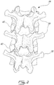
- Fig. 2 is a back view of a portion of the spinal column 36.
- the spinal column (or vertebral column) 36 extends from the skull to the pelvis and is made up of multiple individual bones called vertebrae 38.
- the vertebrae 38 are stacked on top of each other interleaved with discs 40.
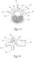
- Figs. 3A and 3B are respectively a top view and a side view of a normal lumbar vertebra 38.
- the vertebra 38 has a back portion 42 and a front portion, called the vertebral body 44, linked by two pedicles 46.
- the back portion 42, the vertebral body 44 and the pedicles 46 define a spinal canal 48, and through which the spinal cord (not shown) passes.
- the back portion 42 has a spinous process 50 protruding toward the back, a transverse process 52 protruding toward each side, two superior articular facets 54 protruding upward and two inferior articular facets 56 protruding downward ( Fig. 3B ).
- the spinous process 50, the transverse processes 52, the superior articular facets 54 and the inferior articular facets 56 are linked by a lamina 58.
- a method and a system for generating a non-imaged plane view of an object, a vertebra in this embodiment, are described herein with reference to Figs. 4 to 12 .
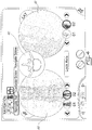
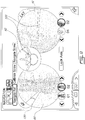
- Fig. 4 shows a screenshot of a graphical user interface (GUI) as displayed on a display device of a computer-assisted surgery (CAS) system.
- GUI graphical user interface
- CAS computer-assisted surgery
- Two imaged, i.e. acquisition-obtained, plane views 60, 61 are represented thereon. These plane views 60, 61 are acquired using a fluoroscopic apparatus.
- the CAS system also allows the tracking and the reproduction on the display device of surgical objects, such as a surgical tool, overlaid on these two plane views 60, 61, as a surgeon places a pedicular screw into a given vertebra for example.
- the imaged plane view 60 located on the left side is a fluoroscopic image of the spine acquired along the antero-posterior plane 34 (see Fig. 1 ).
- the imaged plane view 61 located on the right side is a fluoroscopic image of the spine taken along the sagittal plane 32 (see Fig. 1 ).
- An additional plane view, i.e. a non-imaged plane view 62, is also shown positioned centrally between the antero-posterior plane view image 60 and the sagittal plane view image 61.
- the plane view shown by non-imaged plane view 62 represents a plane view of the spine taken along the axial plane 30 (see in Fig. 1 ).
- the plane view 62 is non-imaged in that it is not obtained from an imaging acquisition but is rather generated from the antero-posterior plane view image 60 and the sagittal plane view image 61 as described hereinbelow.
- the non-imaged plane view 62 is actually generated from a model of a typical vertebra which is defined by a typical shape and a combination of features and dimension parameters. Dimensions of the model are adjusted according to measurements of the dimension parameters performed on the antero-posterior plane view image 60 and the sagittal plane view image 61. It is pointed out that the configuration of the GUI of Fig. 4 is shown as an example. Other configurations may be displayed, with the plane image 62 to the right-hand side or left-hand side, or without the image 60 and/or 61.
- Fig. 5 illustrates the steps of a method 70 for generating a non-imaged plane view of an anatomical part, such as the non-imaged plane view 62 of Fig. 4 , from at least one plane view, such as plane view images 60 and 61 of Fig. 4 .
- a model of the anatomical part such as a model of a typical vertebra or other bone.
- the model generally defines the shape of the anatomical part in general with representative features that are typical to the shape of the anatomical part.
- the dimensions of the general shape are to be adjusted according to dimension parameters related to the features and determined from the plane view images 60 and 61.
- the general shape corresponds to the one shown in Figs. 3A and 3B .
- the features are typically defined by contours of the anatomical part, such as the contours of some of the following elements in the case of a vertebra: the spinous process 50, the transverse processes 52, the superior articular facets 54, the inferior articular facets 56, the pedicles 46 and the vertebral body 44 (see Figs. 3A and 3B ).
- Dimension parameters may comprise the distance between the various contours.
- An example of features and dimension parameters for the specific case of a vertebra are given hereinbelow with reference to Fig. 6A .
- a first plane view and, optionally, a second plane view of the anatomical part are obtained using an imaging device.
- the first and the second plane views are typically orthogonal from one another.
- the first and the second plane views of the anatomical part can typically be any two of an antero-posterior plane view, a sagittal plane view and an axial plane view.
- the first plane view consists of the antero-posterior plane view image 60 and the second plane view consists of the sagittal plane view image 61.
- the first and second plane views are acquired using the same imaging device. Two different imaging devices may also be used to obtain the two orthogonal plane views.
- step 76 features of the anatomical part are identified on the first plane view and also typically on the second plane view. As will be detailed hereinbelow, the features are typically defined by contours of the anatomical part as extracted from the first and the second plane views.
- step 78 values of the dimension parameters are measured on the first plane view and also typically on the second plane view, from the features identified in step 76.
- the distance between various features of the vertebra may be measured from the antero-posterior plane view image 60 and the sagittal plane view image 61.
- the dimension parameters are the distances d 1 , d 2 , d 3 and d 4 as described hereinbelow with reference to Fig. 6A .
- step 80 the model of the anatomical part is displayed in the non-imaged plane view, as dimensioned according to the values measured in step 78. Accordingly, the model is scaled to correspond to the values of the dimension parameters measured in step 78.
- the model of the vertebrae is displayed in the non-imaged plane view 62.
- all of the three views i.e. the first and the second plane views and the non-imaged plane view, can be displayed on the display device (see Fig. 4 for example).
- step 82 the position and the orientation of a surgical object, such as a surgical tool, are tracked relative to the anatomical part while the user manipulates the surgical object in space. As explained below, this is typically made using tracking modules installed on the anatomical part and on the surgical object.
- step 84 a representation of the surgical object to be overlaid in register on the first plane view, the second plane view and/or the non-imaged plane view is generated using the tracked positions and orientations of the surgical object relative to the anatomical part.
- Figs. 6A-6E and 7A-7C are schematic representations of a vertebra, and are provided for illustrative purposes only. The following is used to identify the features of the vertebra in the antero-posterior plane view 60 and the saggital plane view 61.
- Fig. 6A illustrates the model of a vertebra as seen from the antero-posterior plane view 60 and defined by contours.
- the algorithm identifies features of a given target vertebra, which are defined as different contours of the vertebra.
- the contours identified are: the upper vertebral body contour 90, the lower vertebral body contour 92, the left-side vertebral body contour 94, and the right-side vertebral body contour 96, as well as the pedicles contours 98, the spinous process contour 100, and the transverse processes contours 102.
- Each of these contours respectively represent the following elements as represented in Figs. 3A and 3B : the vertebral body 44 from the upper side, lower side, left and right sides, each one of the pedicles 46, the spinous process 50 and the transverse processes 52.
- Distances d 1 , d 2 , d 3 , d 4 , d 5 and d 6 define dimension parameters of the vertebra model, according to the specific example described herein.
- Distances d 1 and d 2 respectively define a distance between the left-side vertebral body contour 94 and the closest pedicle contour 98; and between the right-side vertebral body contour 96 and the closest pedicle contour 98.
- Distances d 3 and d 4 respectively define a distance between the spinous process contour 100 and each one of the pedicle contours 98.
- Distances d 5 and d 6 respectively define a width of the left-side and right-side pedicle contours 98.
- the contour image of Fig. 6A is obtained if the pedicles 46 (see Fig. 3A and 3B ) are placed substantially parallel to the imaging device's axis when acquiring the image 60 in the antero-posterior plane.
- the distances d 1 and d 2 are substantially equivalent or only vary slightly with one another.
- the contour images of Figs. 6D and 6E respectively result.
- the sizes of the contours 102 representing the transverse processes 52 are disproportional with one another and the distances d 1 and d 2 are not substantially equivalent in comparison with those of Fig. 6A .
- the distances d 3 and d 4 are also not substantially equivalent to one another.
- the imaging device and/or the body are oriented with respect to one another such that the distance pairs d 1 , d 2 ; d 3 , d 4 ; and/or d 5 , d 6 are substantially matched.
- the distance pairs do not need to be exactly matched to one another, in order to account for natural incongruence that may exist based on known anatomical information.
- Fig. 7A illustrates the model of a vertebra as seen from the sagittal plane view 61 and defined by contours.
- the upper and lower vertebral body contours 90 and 92 are identified, as well as the front vertebral body contour 104, the back vertebral body contour 106, and the spinous process contour 100.
- a distance d 7 defines another dimension parameter of the vertebra model, according to the specific example described herein. The distance d 7 defines a distance between the front vertebral body contour 104 and the back end of the spinous process contour 100.
- ellipses are formed along the upper and lower vertebral body contours 90 and 92, which may create distortions in the contour data.
- the imaging device and the body are oriented with respect to each other such that ellipses in the vertebral body contour 90 and 92 are eliminated as much as possible.
- the model of the vertebra may then be dimensioned according to selected ones of d 1 , d 2 , d 3 , d 4 , d 5 , d 6 and d 7 and displayed in the non-imaged plane view 62.
- An additional step may be used after the contours are identified, to determine whether each one of the first and second plane views is acceptable for further processing.
- This step may be performed manually by a surgeon using his best judgment, with the help of a computer or not.
- Values of the dimension parameters, such as d 1 , d 2 , d 3 and d 4 , measured from the contours may also be compared using a computer algorithm.
- the algorithm thresholds the measured values and determines if they are within an acceptable margin, indicating whether the plane views acquired are in proper alignment with the anatomical part for further processing towards the generation of the non-imaged plane view.
- the result of the comparison is then optionally used to obtain correct views by reorienting the imaging device used to obtain the plane view with respect to the anatomical part.
- the shape of the vertebra parts on the plane views may be used by the operator to determine whether the alignment was proper between the imaging device and the patient. For instance, a deformed shape of a pedicle may be judged by the operator as a misalignment between the imaging device and the patient.
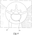
- Fig. 8 shows an enlarged view of the axial plane view 62 generated using the antero-posterior plane view 60 and the sagittal plane view 61.
- the target vertebra 110 is displayed.
- the displayed vertebra 110 is dimensioned in accordance with the measurements taken from the antero-posterior view (d 1 , d 2 , d 3 , and d 4 ) and the measurements taken from the sagittal view (d 5 ).
- a standard model of the vertebra is then used and proportioned according to the dimension parameters d 1 , d 2 , d 3 , d 4 and d 5 .
- the non-imaged axial view 62 of the target vertebra is thus made to correspond to the actual measurements obtained from the imaged plane views 60, 61.
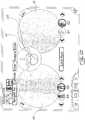
- Fig. 9 shows a screenshot of the GUI as displayed on the display device of the CAS system, wherein a surgical tool 120, such as an awl, a screwdriver, or the like, used in a surgery is displayed.
- the surgical tool 120 is tracked in space for its position and orientation by the CAS system.
- a representation of the tool 120 can then be displayed, overlaid on any one of the antero-posterior plane view 60, the sagittal plane view 61 and the non-imaged plane view 62.
- the display of the tool 120 may be useful for permitting a surgeon to follow the progress (position and orientation in time) of the surgery tool.
- the surgery tool 120 can be displayed along any preferred orthogonal view, or position and orientation information about the surgery tool 120 can be presented on one, two, or all the three views 60, 61, 62, as desired. This typically involves the scaling of the surgery tool 120 proportionally with the plane view(s) 60, 61, 62 on which it is displayed.
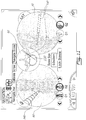
- Fig. 10 shows a screenshot of the GUI as displayed on the display device of the CAS system, wherein a guiding marker 130 is displayed on the non-imaged view 62, as locked into position.
- the guiding marker 130 may in fact be displayed on any one(s) of the plane views 60, 61, 62.
- the guiding marker 130 is used as a guide by the user when moving a surgery tool with respect to the vertebra for inserting a device into the vertebra.
- the guiding marker 130 is used as a guide for inserting a screw in the pedicle of the vertebra.
- the guiding marker 130 is typically positioned by a user and locked into position on the display device.
- the user may validate the alignment of the tool or device relative to the marking guide 130. It is noted that a similar guiding marker may also be used to perform other types of operation on other types of objects.
- Fig. 11 illustrates the navigation process wherein a screw 140 is inserted into the pedicle of a vertebra.
- the screw 140 is being inserted along the guiding marker 130 locked into position.
- the guiding marker 130 is displayed on the non-imaged or axial plane view 62 only and the screw 140 is displayed on one or more of the plane views 60, 61, and 62. This provides the user with multiple aspects from which to see the progress of the surgery.
- the user is being guided by the guiding marker 130 in the axial plane view 62 as the screw advances in the vertebra.
- Fig. 12 illustrates the Computer-Assisted Surgery (CAS) system 200.
- the CAS system 200 has an imaging system 204 for generating a non-imaged plane view of an anatomical part.
- the imaging system 204 comprises an image acquisition device 206, an image processing device 208 and a display device 210.
- the CAS system 200 also makes use of one or more tools 212 with a tool tracking module 214 mounted thereon to track the position and orientation of the tool 212 in space or relative to the anatomical part as an operation, such as a surgery, is being conducted on the anatomical part. Tracking modules may also be mounted to other devices to be used in manipulating the anatomical part.
- Examples of tools used in surgery include an awl and implants or screws that are to be implanted in the anatomical part, such as a bone.
- the anatomical part may also have a part tracking module 215 installed thereon before the operation begins in order to also track a position and an orientation of the anatomical part in space.
- the CAS system 200 also has a navigation processing device 216 and an alignment device 218.
- the image acquisition device 206 is a device permitting imaging of the anatomical part along a first plane view and a second plane view.
- the image acquisition device 206 is a fluoroscope.
- the imaged plane views captured by the image acquisition device 206 are transferred to the image processing device 208, where they are used to generate a non-imaged plane view.
- the image processing device 208 generates the non-imaged plane view according to the method described hereinabove with reference to Fig. 5 . It has a feature identification unit 220, a parameter measuring unit 222 and a model dimensioning unit 223.
- the feature identification unit 220 identifies features of the anatomical part in the first plane view and the second plane view, according to the model of the anatomical part which defines the features and dimension parameters related to the features.
- the parameter measuring unit 222 measures values of the dimension parameters from the features identified by the feature identification unit 220.
- the model dimensioning unit 223 dimensions the model of the anatomical part with the dimension parameters adjusted to the values measured by the parameter measuring unit 222.
- the display device 208 displays, in the non-imaged plane view on the GUI, the model of the anatomical part as dimensioned.
- the first and second plane views are also typically displayed on the GUI.
- the alignment device 218 has an alignment check unit 224 and an alignment control module 226.
- the alignment check unit 224 determines whether imaged plane views captured by the image acquisition device 206 are in alignment with their respective planes as described in reference with Figs. 6B-6E and 7B-7C .
- the alignment check unit 224 typically uses a combination of dimension parameters measured by the parameter measuring unit 222 to determine whether the imaged plane views are in proper alignment, according to predetermined conditions. Alternatively, the operator may determine that the imaged views are improper for misalignment.
- the alignment control module 226 corrects the alignment by reorienting the plane views typically based on feedback provided by the measured dimension parameters, until the alignment check unit 224 determines that the alignment is correct, or until the operator is satisfied.
- any other type of bone such as knee bones for example, may be modeled with features for generating a non-imaged plane view based on dimension parameters measured on imaged plane views.
- Fig. 12 While illustrated in the block diagrams as groups of discrete components communicating with each other via distinct data signal connections, it will be understood by those skilled in the art that the system is implemented from a combination of hardware and software components. Some components may be implemented by a given function or operation of a hardware or software system, and many of the data paths illustrated in Fig. 12 can be implemented by data communication within a computer application or an operating system. Fig. 12 is thus provided solely for illustrative purposes and it is understood that varying embodiments are contemplated.
Landscapes
- Health & Medical Sciences (AREA)
- Engineering & Computer Science (AREA)
- Life Sciences & Earth Sciences (AREA)
- Medical Informatics (AREA)
- Public Health (AREA)
- General Health & Medical Sciences (AREA)
- Surgery (AREA)
- Biomedical Technology (AREA)
- Veterinary Medicine (AREA)
- Molecular Biology (AREA)
- Animal Behavior & Ethology (AREA)
- Heart & Thoracic Surgery (AREA)
- Pathology (AREA)
- Nuclear Medicine, Radiotherapy & Molecular Imaging (AREA)
- Physics & Mathematics (AREA)
- Biophysics (AREA)
- Radiology & Medical Imaging (AREA)
- High Energy & Nuclear Physics (AREA)
- Optics & Photonics (AREA)
- Human Computer Interaction (AREA)
- Primary Health Care (AREA)
- Epidemiology (AREA)
- Oral & Maxillofacial Surgery (AREA)
- Robotics (AREA)
- Dentistry (AREA)
- Data Mining & Analysis (AREA)
- Databases & Information Systems (AREA)
- Surgical Instruments (AREA)
- Apparatus For Radiation Diagnosis (AREA)
Claims (17)
- Verfahren (70) zur Erzeugung einer Anzeige eines nachverfolgten chirurgischen Objekts relativ zu einernicht abgebildeten Querebenenansicht (62) eines Wirbels bei einer computergestützten Operation, wobei das Verfahren Folgendes umfasst:Bereitstellen (72) eines Modells des Wirbels, umfassend Merkmale und Abmessungsparameter, die sich auf die Merkmale beziehen;Erhalten (74) mindestens einer ersten Ebenenansicht (60) des Wirbels;Identifizieren (76) der Merkmale in der mindestens ersten Ebenenansicht (60);Messen (78) von Werten der Abmessungsparameter von den in der mindestens ersten Ebenenansicht (60) identifizierten Merkmalen;Erzeugen, in der nicht abgebildeten Querebenenansicht (62), des Modells, das mit den an die Werte angepassten Dimensionsparametern dimensioniert ist;Anzeigen (80), in der nicht abgebildeten Querebenenansicht (62), des Modells, das mit den an die Werte angepassten Dimensionsparametern dimensioniert ist;Nachverfolgen (82) einer Position und Ausrichtung eines chirurgischen Objekts relativ zu dem Wirbel, während ein Nutzer das chirurgische Objekt im Raum manipuliert;Erzeugen (84) einer Darstellung des chirurgischen Objekts, die in Übereinstimmung über die nicht abgebildete Ansicht (62) gelegt werden soll, mithilfe der nachverfolgten Position und Ausrichtung.
- Verfahren (70) nach Anspruch 1, ferner umfassend das Erhalten einer zweiten Ebenenansicht des Wirbels, wobei die erste Ebenenansicht (60) und die zweite Ebenenansicht (61) entlang unterschiedlicher Ausrichtungen relativ zum Wirbel erhalten werden:wobei das Identifizieren der Merkmale das Identifizieren der Merkmale in der ersten Ebenenansicht (60) und der zweiten Ebenenansicht (61) umfasst; undwobei das Messen von Werten das Messen von Werten der Abmessungsparameter von den Merkmalen umfasst, die in der ersten Ebenenansicht (60) und der zweiten Ebenenansicht (61) identifiziert wurden.
- Verfahren (70) nach Anspruch 1, ferner umfassend:Bestimmen, ob sich eine durch die erste Ebenenansicht (60) dargestellte Ebene in Ausrichtung mit einer entsprechenden vordefinierten Referenzebene befindet, die sich von der Querebene unterscheidet, die durch den Wirbel definiert ist; undwenn sich die durch die erste Ebenenansicht dargestellte Ebene nicht in Ausrichtung befindet:Korrigieren der Ausrichtung; undnochmaliges Erhalten der ersten Ebenenansicht (60) des Wirbels mit der korrigierten Ausrichtung.
- Verfahren (70) nach Anspruch 3, wobei das Bestimmen, ob sich die durch die erste Ebenenansicht (60) dargestellte Ebene in Ausrichtung mit der entsprechenden vordefinierten Referenzebene befindet, umfasst:Vergleichen der gemessenen Werte der Abmessungsparamter mit vorgegebenen Schwellwerten, die sich auf den Wirbel beziehen, um zu bestimmen, ob die gemessenen Werte der Abmessungsparameter innerhalb vorgegebener Grenzen liegen, was eine korrekte Ausrichtung anzeigt.
- Verfahren (70) nach Anspruch 2, wobei die erste Ebenenansicht (60) entlang einer antero-posterioren Ebene erhalten wird, und die zweite Ebenenansicht (61) entlang einer sagittalen Ebene erhalten wird.
- Verfahren (70) nach Anspruch 1, wobei:das Identifizieren der Merkmale das Identifizieren einer Wirbelkörper-Seitenkontur, einer Pedikelkontur und einer Dornfortsatzkontur umfasst.
- Verfahren (70) nach Anspruch 6, wobei das Messen der Werte das Messen eines Abstands zwischen der Wirbelkörper-Seitenkontur und der Pedikelkontur und eines Abstands zwischen der Dornfortsatzkontur und der Pedikelkontur umfasst.
- Verfahren (70) nach Anspruch 2, wobei das Anzeigen das Anzeigen der ersten Ebenenansicht (60), der zweiten Ebenenansicht (61) und der nicht abgebildeten Querebenenansicht (62) in derselben graphischen Nutzerschnittstelle eines computerunterstützten Operationssystems umfasst.
- Verfahren (70) nach Anspruch 1, wobei das Erhalten einer ersten Ebenenansicht (60) das Erwerben der ersten Ebenenansicht mithilfe einer fluoroskopischen Bildgebungsvorrichtung umfasst.
- Computerunterstütztes Operationssystem (200) zum Erzeugen einer Anzeige eines nachverfolgten chirurgischen Objekts relativ zu einer nicht abgebildeten Querebenenansicht eines Wirbels zum Unterstützen einer Operation, wobei das System Folgendes umfasst:eine Bildgebungserwerbungsvorrichtung (206) mit einer ersten Achse zum Erhalten einer ersten Ebenenansicht des Wirbels;eine Bilderzeugungsvorrichtung (208), die ein Modell des Wirbels bereitstellt, umfassend eine Merkmalidentifikationseinheit (220) zum Identifizieren von Merkmalen des Wirbels in mindestens der ersten Ebenenansicht;eine Parametermesseinheit (222) zum Messen von Werten von Abmessungsparametern von den identifizierten Merkmalen; undeine Modelldimensionierungseinheit (223) zum Dimensionieren des Modells des Wirbels, in der nicht abgebildeten Querebenenansicht, mit Dimensionsparamtern, die an die Werte angepasst sind;eine Anzeigevorrichtung zum Anzeigen, in der nicht abgebildeten Querebenenansicht, des Modells, wie es dimensioniert ist; undeine Navigationsverarbeitungsvorrichtung (216) zum Erzeugen einer Darstellung eines chirurgischen Objekts, die in Übereinstimmung über die nicht abgebildete Querebenenansicht gelegt werden soll, mithilfe einer nachverfolgten Position und Ausrichtung des chirurgischen Objekts relativ zum Wirbel, um visuelles Feedback auf mindestens der nicht abgebildeten Querebenenansicht bereitzustellen, während das chirurgische Objekt manipuliert wird.
- System nach Anspruch 10, wobei die Bildgebungserwerbungsvorrichtung (206) eine zweite Achse zum Erhalten einer zweiten Ebenenansicht des Wirbels aufweist, wobei die Merkmalidentifikationseinheit (220) Merkmale des Wirbels in der ersten Ebenenansicht und der zweiten Ebenenansicht identifiziert, und die Parametermesseinheit (222) Werte der Abmessungsparameter von den in der ersten Ebenenansicht und in der zweiten Ebenenansicht identifizierten Merkmalen misst.
- System nach Anspruch 11, wobei die erste Ebenenansicht eine antero-posteriore Ansicht ist und die zweite Ebenenansicht eine sagittale Ebenenansicht ist.
- System nach Anspruch 10, ferner umfassend:eine Ausrichtungskontrolleinheit (224) zum Bestimmen, ob sich eine Ebene, die durch die erste Ebenenansicht dargestellt wird, in Ausrichtung mit einer entsprechenden einer vordefinierten Referenzebene befindet, die sich von der Querebene unterscheidet, die durch den Wirbel definiert ist, undein Ausrichtungskontrollmodul (226) zum Korrigieren der Ausrichtung, wenn sich die Ebene, die durch die erste Ebenenansicht dargestellt ist, nicht in Ausrichtung befindet, durch Neuausrichten der Bildgebungserwerbungsvorrichtung (206), um die erste Ebenenansicht in Ausrichtung mit dem Wirbel zu erhalten.
- System nach Anspruch 13, wobei die Ausrichtungskontrolleinheit angeordnet ist, um zu bestimmen, ob die durch die erste Ebenenansicht dargestellte Ebene sich in Ausrichtung mit der entsprechenden vordefinierten Referenzebene durch Vergleichen der gemessenen Werte der Abmessungsparameter mit vorgegebenen Schwellwerten, die sich auf das Wirbel beziehen, um zu bestimmen, ob die gemessenen Werte der Abmessungsparameter innerhalb vorgegebener Grenzen liegen, was eine korrekte Ausrichtung anzeigt.
- System nach Anspruch 10, wobei die Merkmale eine Wirbelkörper-Seitenkontur, eine Pedikelkontur und eine Wirbelfortsatzkontur umfassen.
- System nach Anspruch 15, wobei die Abmessungsparameter einen Abstand zwischen der Wirbelkörper-Seitenkontur und der der Pedikelkontur und einen Abstand zwischen der Dornfortsatzkontur und der Pedikelkontur umfassen.
- System nach Anspruch 10, wobei die Bildgebungserwerbungsvorrichtung (206) eine fluoroskopische Bildgebungsvorrichtung umfasst.
Applications Claiming Priority (2)
| Application Number | Priority Date | Filing Date | Title |
|---|---|---|---|
| US96047607P | 2007-10-01 | 2007-10-01 | |
| PCT/CA2008/001730 WO2009043150A1 (en) | 2007-10-01 | 2008-09-30 | Construction of a non-imaged view of an object using acquired images |
Publications (3)
| Publication Number | Publication Date |
|---|---|
| EP2162086A1 EP2162086A1 (de) | 2010-03-17 |
| EP2162086A4 EP2162086A4 (de) | 2012-12-05 |
| EP2162086B1 true EP2162086B1 (de) | 2019-02-27 |
Family
ID=40508432
Family Applications (1)
| Application Number | Title | Priority Date | Filing Date |
|---|---|---|---|
| EP08800409.8A Not-in-force EP2162086B1 (de) | 2007-10-01 | 2008-09-30 | Herstellung einer nicht abgebildeten ansicht eines objekts mithilfe erfasster bilder |
Country Status (4)
| Country | Link |
|---|---|
| US (1) | US9826919B2 (de) |
| EP (1) | EP2162086B1 (de) |
| CA (1) | CA2692543A1 (de) |
| WO (1) | WO2009043150A1 (de) |
Families Citing this family (11)
| Publication number | Priority date | Publication date | Assignee | Title |
|---|---|---|---|---|
| EP2164042B1 (de) * | 2008-09-10 | 2017-11-08 | Brainlab AG | Verfahren zur Überprüfung der relativen Lage von Knochenstrukturen |
| WO2011104028A1 (en) * | 2010-02-26 | 2011-09-01 | Spontech Spine Intelligence Group Ag | Computer program for spine mobility simulation and spine simulation method |
| USD774047S1 (en) * | 2013-06-28 | 2016-12-13 | Hitachi High-Technologies Corporation | Display screen with graphical user interface |
| CN105701438B (zh) * | 2014-11-26 | 2020-06-23 | 东芝医疗系统株式会社 | 医学图像处理装置和方法以及医学成像设备 |
| WO2017085529A1 (en) * | 2015-11-19 | 2017-05-26 | Eos Imaging | Method of preoperative planning to correct spine misalignment of a patient |
| KR102205866B1 (ko) * | 2018-12-14 | 2021-01-21 | 경북대학교 산학협력단 | 척추체 회전 측정 방법, 이를 수행하기 위한 장치 및 기록매체 |
| US20210177526A1 (en) * | 2019-12-16 | 2021-06-17 | Orthosoft Ulc | Method and system for spine tracking in computer-assisted surgery |
| WO2023101961A1 (en) * | 2021-11-30 | 2023-06-08 | Endoquest Robotics, Inc. | Display systems for robotic surgical systems |
| CN114259298B (zh) * | 2022-02-25 | 2022-04-29 | 博志生物科技(深圳)有限公司 | 一种规划椎弓根后路内固定置钉轨迹的数字可视化方法 |
| US20250248770A1 (en) * | 2022-10-28 | 2025-08-07 | Medtronic, Inc. | System and method for illustrating a pose of an object |
| WO2024089503A1 (en) * | 2022-10-28 | 2024-05-02 | Medtronic, Inc. | System and method for illustrating a pose of an object |
Family Cites Families (30)
| Publication number | Priority date | Publication date | Assignee | Title |
|---|---|---|---|---|
| US5227969A (en) * | 1988-08-01 | 1993-07-13 | W. L. Systems, Inc. | Manipulable three-dimensional projection imaging method |
| US5765561A (en) * | 1994-10-07 | 1998-06-16 | Medical Media Systems | Video-based surgical targeting system |
| US5787889A (en) * | 1996-12-18 | 1998-08-04 | University Of Washington | Ultrasound imaging with real time 3D image reconstruction and visualization |
| DE19854241B4 (de) * | 1998-11-24 | 2014-03-06 | Siemens Aktiengesellschaft | Verfahren zum Darstellen von an einem Anzeigemonitor wiedergebbaren Bildern sowie Vorrichtung zum Verarbeiten und Wiedergeben digitaler Bilder |
| FR2810141B1 (fr) * | 2000-06-07 | 2002-08-23 | Commissariat Energie Atomique | Procede de reconstruction accelere d'une image tridimentionnelle |
| US6907281B2 (en) * | 2000-09-07 | 2005-06-14 | Ge Medical Systems | Fast mapping of volumetric density data onto a two-dimensional screen |
| US6491429B1 (en) * | 2000-09-08 | 2002-12-10 | Ao-Development Institute Davos | Method of automatic guiding a C-arm X-ray device |
| WO2003005298A2 (en) * | 2001-07-06 | 2003-01-16 | Koninklijke Philips Electronics N.V. | Image processing method for interacting with a 3-d surface represented in a 3-d image |
| US6814489B2 (en) * | 2001-11-23 | 2004-11-09 | Ge Medical Systems Global Technology Company, Llc | 3D reconstruction system and method utilizing a variable X-ray source to image distance |
| EP1348393B1 (de) * | 2002-03-27 | 2007-03-21 | BrainLAB AG | Medizinische Navigation bzw. prä-operative Behandlungsplanung mit Unterstützung durch generische Patientendaten |
| US7787932B2 (en) * | 2002-04-26 | 2010-08-31 | Brainlab Ag | Planning and navigation assistance using two-dimensionally adapted generic and detected patient data |
| FI116750B (fi) * | 2002-08-28 | 2006-02-15 | Instrumentarium Corp | Lääketieteellisen röntgenkuvauksen menetelmä ja järjestely |
| FR2856170B1 (fr) * | 2003-06-10 | 2005-08-26 | Biospace Instr | Procede d'imagerie radiographique pour la reconstruction tridimensionnelle, dispositif et programme d'ordinateur pour mettre en oeuvre ce procede |
| US7215810B2 (en) * | 2003-07-23 | 2007-05-08 | Orametrix, Inc. | Method for creating single 3D surface model from a point cloud |
| US6980922B2 (en) * | 2003-10-09 | 2005-12-27 | Computational Biodynamics, Llc | Computer simulation model for determining damage to the human central nervous system |
| US7596258B2 (en) * | 2003-11-10 | 2009-09-29 | Kabushiki Kaisha Toshiba | Image processor |
| DE102004004620A1 (de) * | 2004-01-29 | 2005-08-25 | Siemens Ag | Verfahren zur Registrierung und Überlagerung von Bilddaten bei Serienaufnahmen in der medizinischen Bildgebung |
| DE102004016586A1 (de) * | 2004-03-31 | 2005-11-03 | Siemens Ag | Bildrekonstruktionseinrichtung für ein Röntgengerät sowie Verfahren zur lokalen 3D-Rekonstruktion eines Objektbereiches |
| US8515527B2 (en) * | 2004-10-13 | 2013-08-20 | General Electric Company | Method and apparatus for registering 3D models of anatomical regions of a heart and a tracking system with projection images of an interventional fluoroscopic system |
| DE102004051401A1 (de) * | 2004-10-21 | 2006-05-24 | Siemens Ag | Verfahren zur Befundung in der dreidimensionalen Bildgebung, insbesondere in der Mammographie |
| US7725165B2 (en) | 2004-12-07 | 2010-05-25 | M2S, Inc. | Method and apparatus for visualizing anatomical structures |
| DE102005022540B4 (de) * | 2005-05-17 | 2007-07-05 | Siemens Ag | Verfahren zur Minimierung von Bildartefakten und medizinisches Bildgebungssystem |
| FR2887058B1 (fr) | 2005-06-10 | 2007-08-31 | Daniel Ackerman | Procede et dispositif de reconstruction 3d d'un objet a partir de plusieurs images 2d |
| TWI282268B (en) * | 2005-09-15 | 2007-06-11 | Univ Chung Shan Medical | Medical image system and method for measuring vertebral axial rotation |
| JP2007135658A (ja) * | 2005-11-15 | 2007-06-07 | Ge Medical Systems Global Technology Co Llc | X線ct装置およびx線ct透視装置 |
| US7773786B2 (en) * | 2005-11-22 | 2010-08-10 | General Electric Company | Method and apparatus for three-dimensional interactive tools for semi-automatic segmentation and editing of image objects |
| ATE470921T1 (de) | 2005-12-14 | 2010-06-15 | Koninkl Philips Electronics Nv | Verfahren und einrichtung zum miteinander in beziehung setzen von medizinischen 3d-datenbild- ansichtsebenen |
| JP4836122B2 (ja) * | 2006-02-09 | 2011-12-14 | 国立大学法人浜松医科大学 | 手術支援装置、方法及びプログラム |
| DE502006002892D1 (de) * | 2006-08-14 | 2009-04-02 | Brainlab Ag | Registrierung von MR-Daten anhand generischer Modelle |
| EP1892668B1 (de) * | 2006-08-22 | 2012-10-03 | BrainLAB AG | Registrierung von Bilddaten |
-
2008
- 2008-09-30 EP EP08800409.8A patent/EP2162086B1/de not_active Not-in-force
- 2008-09-30 CA CA 2692543 patent/CA2692543A1/en not_active Withdrawn
- 2008-09-30 WO PCT/CA2008/001730 patent/WO2009043150A1/en not_active Ceased
- 2008-09-30 US US12/241,724 patent/US9826919B2/en active Active
Non-Patent Citations (1)
| Title |
|---|
| None * |
Also Published As
| Publication number | Publication date |
|---|---|
| WO2009043150A1 (en) | 2009-04-09 |
| US9826919B2 (en) | 2017-11-28 |
| US20090087052A1 (en) | 2009-04-02 |
| CA2692543A1 (en) | 2009-04-09 |
| EP2162086A4 (de) | 2012-12-05 |
| EP2162086A1 (de) | 2010-03-17 |
Similar Documents
| Publication | Publication Date | Title |
|---|---|---|
| US9826919B2 (en) | Construction of a non-imaged view of an object using acquired images | |
| US12295762B2 (en) | Method for verifying hard tissue location using implant imaging | |
| US20250221747A1 (en) | Stereotactic Computer Assisted Surgery Method and System | |
| CN109195527B (zh) | 用于与骨骼手术一起使用的设备及方法 | |
| US11806197B2 (en) | Patient-matched apparatus for use in spine related surgical procedures and methods for using the same | |
| US11633254B2 (en) | Patient-matched apparatus for use in augmented reality assisted surgical procedures and methods for using the same | |
| US5772594A (en) | Fluoroscopic image guided orthopaedic surgery system with intraoperative registration | |
| US8320992B2 (en) | Method and system for superimposing three dimensional medical information on a three dimensional image | |
| CN114846517A (zh) | 确定2d医学图像中的对象之间的相对3d位置和取向 | |
| US11672607B2 (en) | Systems, devices, and methods for surgical navigation with anatomical tracking | |
| US20080177203A1 (en) | Surgical navigation planning system and method for placement of percutaneous instrumentation and implants | |
| US12440276B2 (en) | Systems and methods for presurgical planning | |
| KR20190058190A (ko) | 증강현실 기술을 이용한 척추 수술 네비게이션 시스템 및 방법 | |
| Devito et al. | History and evolution of spinal robotics in pediatric spinal deformity | |
| US12357413B2 (en) | Patient-matched apparatus for use in spine related surgical procedures and methods for using the same | |
| US10762647B2 (en) | Motion compensation in hybrid X-ray/camera interventions | |
| CN120745004B (zh) | 一种椎弓根钉导向导板的设计方法及其使用方法 | |
| US20260130716A1 (en) | Systems and methods for presurgical planning | |
| US20250295470A1 (en) | Patient-matched apparatus for use in spine related surgical procedures and methods for using the same | |
| Pijpker | 3D Virtual Surgical Planning and Patient-Specific Instrumentation in Spine Surgery | |
| RO128174A2 (ro) | Metodă şi sistem inteligent bazat pe raze x pentru instruirea chirurgilor în inserarea şuruburilor pediculare |
Legal Events
| Date | Code | Title | Description |
|---|---|---|---|
| PUAI | Public reference made under article 153(3) epc to a published international application that has entered the european phase |
Free format text: ORIGINAL CODE: 0009012 |
|
| 17P | Request for examination filed |
Effective date: 20100114 |
|
| AK | Designated contracting states |
Kind code of ref document: A1 Designated state(s): AT BE BG CH CY CZ DE DK EE ES FI FR GB GR HR HU IE IS IT LI LT LU LV MC MT NL NO PL PT RO SE SI SK TR |
|
| AX | Request for extension of the european patent |
Extension state: AL BA MK RS |
|
| DAX | Request for extension of the european patent (deleted) | ||
| A4 | Supplementary search report drawn up and despatched |
Effective date: 20121107 |
|
| RIC1 | Information provided on ipc code assigned before grant |
Ipc: H04N 5/321 20060101ALI20121101BHEP Ipc: A61B 19/00 20060101AFI20121101BHEP Ipc: A61B 5/107 20060101ALI20121101BHEP |
|
| STAA | Information on the status of an ep patent application or granted ep patent |
Free format text: STATUS: EXAMINATION IS IN PROGRESS |
|
| 17Q | First examination report despatched |
Effective date: 20170314 |
|
| REG | Reference to a national code |
Ref country code: DE Ref legal event code: R079 Ref document number: 602008059153 Country of ref document: DE Free format text: PREVIOUS MAIN CLASS: A61B0019000000 Ipc: A61B0006000000 |
|
| GRAP | Despatch of communication of intention to grant a patent |
Free format text: ORIGINAL CODE: EPIDOSNIGR1 |
|
| STAA | Information on the status of an ep patent application or granted ep patent |
Free format text: STATUS: GRANT OF PATENT IS INTENDED |
|
| RIC1 | Information provided on ipc code assigned before grant |
Ipc: A61B 6/00 20060101AFI20180524BHEP Ipc: A61B 34/20 20160101ALI20180524BHEP Ipc: A61B 6/12 20060101ALN20180524BHEP Ipc: A61B 5/00 20060101ALI20180524BHEP Ipc: G16H 50/50 20180101ALN20180524BHEP Ipc: A61B 34/10 20160101ALN20180524BHEP Ipc: A61B 5/107 20060101ALN20180524BHEP Ipc: A61B 5/055 20060101ALN20180524BHEP Ipc: G06F 19/00 20180101ALN20180524BHEP |
|
| RIC1 | Information provided on ipc code assigned before grant |
Ipc: A61B 5/00 20060101ALI20180531BHEP Ipc: G16H 50/50 20180101ALN20180531BHEP Ipc: A61B 34/20 20160101ALI20180531BHEP Ipc: A61B 5/107 20060101ALN20180531BHEP Ipc: A61B 34/10 20160101ALN20180531BHEP Ipc: A61B 6/00 20060101AFI20180531BHEP Ipc: A61B 5/055 20060101ALN20180531BHEP Ipc: G06F 19/00 20180101ALN20180531BHEP Ipc: A61B 6/12 20060101ALN20180531BHEP |
|
| RIC1 | Information provided on ipc code assigned before grant |
Ipc: A61B 34/10 20160101ALN20180606BHEP Ipc: G16H 50/50 20180101ALN20180606BHEP Ipc: A61B 5/107 20060101ALN20180606BHEP Ipc: A61B 34/20 20160101ALI20180606BHEP Ipc: A61B 5/00 20060101ALI20180606BHEP Ipc: A61B 6/12 20060101ALN20180606BHEP Ipc: A61B 6/00 20060101AFI20180606BHEP Ipc: G06F 19/00 20180101ALN20180606BHEP Ipc: A61B 5/055 20060101ALN20180606BHEP |
|
| INTG | Intention to grant announced |
Effective date: 20180618 |
|
| GRAS | Grant fee paid |
Free format text: ORIGINAL CODE: EPIDOSNIGR3 |
|
| GRAA | (expected) grant |
Free format text: ORIGINAL CODE: 0009210 |
|
| STAA | Information on the status of an ep patent application or granted ep patent |
Free format text: STATUS: THE PATENT HAS BEEN GRANTED |
|
| AK | Designated contracting states |
Kind code of ref document: B1 Designated state(s): AT BE BG CH CY CZ DE DK EE ES FI FR GB GR HR HU IE IS IT LI LT LU LV MC MT NL NO PL PT RO SE SI SK TR |
|
| REG | Reference to a national code |
Ref country code: GB Ref legal event code: FG4D |
|
| REG | Reference to a national code |
Ref country code: CH Ref legal event code: EP |
|
| REG | Reference to a national code |
Ref country code: CH Ref legal event code: NV Representative=s name: MICHELI AND CIE SA, CH Ref country code: CH Ref legal event code: PCOW Free format text: NEW ADDRESS: 75 QUEEN STREET, SUITE 3300, MONTREAL, QUEBEC H3C 2N6 (CA) Ref country code: AT Ref legal event code: REF Ref document number: 1100184 Country of ref document: AT Kind code of ref document: T Effective date: 20190315 |
|
| REG | Reference to a national code |
Ref country code: IE Ref legal event code: FG4D |
|
| REG | Reference to a national code |
Ref country code: DE Ref legal event code: R096 Ref document number: 602008059153 Country of ref document: DE |
|
| RAP2 | Party data changed (patent owner data changed or rights of a patent transferred) |
Owner name: ORTHOSOFT INC. |
|
| REG | Reference to a national code |
Ref country code: NL Ref legal event code: MP Effective date: 20190227 |
|
| REG | Reference to a national code |
Ref country code: LT Ref legal event code: MG4D |
|
| PG25 | Lapsed in a contracting state [announced via postgrant information from national office to epo] |
Ref country code: LT Free format text: LAPSE BECAUSE OF FAILURE TO SUBMIT A TRANSLATION OF THE DESCRIPTION OR TO PAY THE FEE WITHIN THE PRESCRIBED TIME-LIMIT Effective date: 20190227 Ref country code: NO Free format text: LAPSE BECAUSE OF FAILURE TO SUBMIT A TRANSLATION OF THE DESCRIPTION OR TO PAY THE FEE WITHIN THE PRESCRIBED TIME-LIMIT Effective date: 20190527 Ref country code: FI Free format text: LAPSE BECAUSE OF FAILURE TO SUBMIT A TRANSLATION OF THE DESCRIPTION OR TO PAY THE FEE WITHIN THE PRESCRIBED TIME-LIMIT Effective date: 20190227 Ref country code: NL Free format text: LAPSE BECAUSE OF FAILURE TO SUBMIT A TRANSLATION OF THE DESCRIPTION OR TO PAY THE FEE WITHIN THE PRESCRIBED TIME-LIMIT Effective date: 20190227 Ref country code: PT Free format text: LAPSE BECAUSE OF FAILURE TO SUBMIT A TRANSLATION OF THE DESCRIPTION OR TO PAY THE FEE WITHIN THE PRESCRIBED TIME-LIMIT Effective date: 20190627 Ref country code: SE Free format text: LAPSE BECAUSE OF FAILURE TO SUBMIT A TRANSLATION OF THE DESCRIPTION OR TO PAY THE FEE WITHIN THE PRESCRIBED TIME-LIMIT Effective date: 20190227 |
|
| PG25 | Lapsed in a contracting state [announced via postgrant information from national office to epo] |
Ref country code: IS Free format text: LAPSE BECAUSE OF FAILURE TO SUBMIT A TRANSLATION OF THE DESCRIPTION OR TO PAY THE FEE WITHIN THE PRESCRIBED TIME-LIMIT Effective date: 20190627 Ref country code: LV Free format text: LAPSE BECAUSE OF FAILURE TO SUBMIT A TRANSLATION OF THE DESCRIPTION OR TO PAY THE FEE WITHIN THE PRESCRIBED TIME-LIMIT Effective date: 20190227 Ref country code: HR Free format text: LAPSE BECAUSE OF FAILURE TO SUBMIT A TRANSLATION OF THE DESCRIPTION OR TO PAY THE FEE WITHIN THE PRESCRIBED TIME-LIMIT Effective date: 20190227 Ref country code: GR Free format text: LAPSE BECAUSE OF FAILURE TO SUBMIT A TRANSLATION OF THE DESCRIPTION OR TO PAY THE FEE WITHIN THE PRESCRIBED TIME-LIMIT Effective date: 20190528 Ref country code: BG Free format text: LAPSE BECAUSE OF FAILURE TO SUBMIT A TRANSLATION OF THE DESCRIPTION OR TO PAY THE FEE WITHIN THE PRESCRIBED TIME-LIMIT Effective date: 20190527 |
|
| REG | Reference to a national code |
Ref country code: AT Ref legal event code: MK05 Ref document number: 1100184 Country of ref document: AT Kind code of ref document: T Effective date: 20190227 |
|
| PG25 | Lapsed in a contracting state [announced via postgrant information from national office to epo] |
Ref country code: ES Free format text: LAPSE BECAUSE OF FAILURE TO SUBMIT A TRANSLATION OF THE DESCRIPTION OR TO PAY THE FEE WITHIN THE PRESCRIBED TIME-LIMIT Effective date: 20190227 Ref country code: DK Free format text: LAPSE BECAUSE OF FAILURE TO SUBMIT A TRANSLATION OF THE DESCRIPTION OR TO PAY THE FEE WITHIN THE PRESCRIBED TIME-LIMIT Effective date: 20190227 Ref country code: EE Free format text: LAPSE BECAUSE OF FAILURE TO SUBMIT A TRANSLATION OF THE DESCRIPTION OR TO PAY THE FEE WITHIN THE PRESCRIBED TIME-LIMIT Effective date: 20190227 Ref country code: RO Free format text: LAPSE BECAUSE OF FAILURE TO SUBMIT A TRANSLATION OF THE DESCRIPTION OR TO PAY THE FEE WITHIN THE PRESCRIBED TIME-LIMIT Effective date: 20190227 Ref country code: CZ Free format text: LAPSE BECAUSE OF FAILURE TO SUBMIT A TRANSLATION OF THE DESCRIPTION OR TO PAY THE FEE WITHIN THE PRESCRIBED TIME-LIMIT Effective date: 20190227 Ref country code: SK Free format text: LAPSE BECAUSE OF FAILURE TO SUBMIT A TRANSLATION OF THE DESCRIPTION OR TO PAY THE FEE WITHIN THE PRESCRIBED TIME-LIMIT Effective date: 20190227 Ref country code: IT Free format text: LAPSE BECAUSE OF FAILURE TO SUBMIT A TRANSLATION OF THE DESCRIPTION OR TO PAY THE FEE WITHIN THE PRESCRIBED TIME-LIMIT Effective date: 20190227 |
|
| PGFP | Annual fee paid to national office [announced via postgrant information from national office to epo] |
Ref country code: IE Payment date: 20190807 Year of fee payment: 12 |
|
| REG | Reference to a national code |
Ref country code: CH Ref legal event code: PFA Owner name: ORTHOSOFT ULC, CA Free format text: FORMER OWNER: ORTHOSOFT INC., CA |
|
| REG | Reference to a national code |
Ref country code: DE Ref legal event code: R097 Ref document number: 602008059153 Country of ref document: DE |
|
| PG25 | Lapsed in a contracting state [announced via postgrant information from national office to epo] |
Ref country code: PL Free format text: LAPSE BECAUSE OF FAILURE TO SUBMIT A TRANSLATION OF THE DESCRIPTION OR TO PAY THE FEE WITHIN THE PRESCRIBED TIME-LIMIT Effective date: 20190227 |
|
| RAP2 | Party data changed (patent owner data changed or rights of a patent transferred) |
Owner name: ORTHOSOFT ULC |
|
| PG25 | Lapsed in a contracting state [announced via postgrant information from national office to epo] |
Ref country code: AT Free format text: LAPSE BECAUSE OF FAILURE TO SUBMIT A TRANSLATION OF THE DESCRIPTION OR TO PAY THE FEE WITHIN THE PRESCRIBED TIME-LIMIT Effective date: 20190227 |
|
| PLBE | No opposition filed within time limit |
Free format text: ORIGINAL CODE: 0009261 |
|
| STAA | Information on the status of an ep patent application or granted ep patent |
Free format text: STATUS: NO OPPOSITION FILED WITHIN TIME LIMIT |
|
| REG | Reference to a national code |
Ref country code: DE Ref legal event code: R082 Ref document number: 602008059153 Country of ref document: DE Representative=s name: PIOTROWICZ, PAWEL JAN ANDRZEJ, DR., GB Ref country code: DE Ref legal event code: R081 Ref document number: 602008059153 Country of ref document: DE Owner name: ORTHOSOFT ULC, CA Free format text: FORMER OWNER: ORTHOSOFT, INC., MONTREAL, QUEBEC, CA |
|
| 26N | No opposition filed |
Effective date: 20191128 |
|
| PG25 | Lapsed in a contracting state [announced via postgrant information from national office to epo] |
Ref country code: SI Free format text: LAPSE BECAUSE OF FAILURE TO SUBMIT A TRANSLATION OF THE DESCRIPTION OR TO PAY THE FEE WITHIN THE PRESCRIBED TIME-LIMIT Effective date: 20190227 |
|
| PG25 | Lapsed in a contracting state [announced via postgrant information from national office to epo] |
Ref country code: TR Free format text: LAPSE BECAUSE OF FAILURE TO SUBMIT A TRANSLATION OF THE DESCRIPTION OR TO PAY THE FEE WITHIN THE PRESCRIBED TIME-LIMIT Effective date: 20190227 |
|
| PG25 | Lapsed in a contracting state [announced via postgrant information from national office to epo] |
Ref country code: MC Free format text: LAPSE BECAUSE OF FAILURE TO SUBMIT A TRANSLATION OF THE DESCRIPTION OR TO PAY THE FEE WITHIN THE PRESCRIBED TIME-LIMIT Effective date: 20190227 |
|
| PG25 | Lapsed in a contracting state [announced via postgrant information from national office to epo] |
Ref country code: LU Free format text: LAPSE BECAUSE OF NON-PAYMENT OF DUE FEES Effective date: 20190930 |
|
| REG | Reference to a national code |
Ref country code: BE Ref legal event code: MM Effective date: 20190930 |
|
| PG25 | Lapsed in a contracting state [announced via postgrant information from national office to epo] |
Ref country code: BE Free format text: LAPSE BECAUSE OF NON-PAYMENT OF DUE FEES Effective date: 20190930 |
|
| REG | Reference to a national code |
Ref country code: DE Ref legal event code: R082 Ref document number: 602008059153 Country of ref document: DE Representative=s name: VENNER SHIPLEY GERMANY LLP, DE Ref country code: DE Ref legal event code: R082 Ref document number: 602008059153 Country of ref document: DE Representative=s name: VENNER SHIPLEY LLP, DE |
|
| PGFP | Annual fee paid to national office [announced via postgrant information from national office to epo] |
Ref country code: GB Payment date: 20200813 Year of fee payment: 13 |
|
| PGFP | Annual fee paid to national office [announced via postgrant information from national office to epo] |
Ref country code: CH Payment date: 20200804 Year of fee payment: 13 |
|
| PG25 | Lapsed in a contracting state [announced via postgrant information from national office to epo] |
Ref country code: CY Free format text: LAPSE BECAUSE OF FAILURE TO SUBMIT A TRANSLATION OF THE DESCRIPTION OR TO PAY THE FEE WITHIN THE PRESCRIBED TIME-LIMIT Effective date: 20190227 |
|
| PG25 | Lapsed in a contracting state [announced via postgrant information from national office to epo] |
Ref country code: MT Free format text: LAPSE BECAUSE OF FAILURE TO SUBMIT A TRANSLATION OF THE DESCRIPTION OR TO PAY THE FEE WITHIN THE PRESCRIBED TIME-LIMIT Effective date: 20190227 Ref country code: HU Free format text: LAPSE BECAUSE OF FAILURE TO SUBMIT A TRANSLATION OF THE DESCRIPTION OR TO PAY THE FEE WITHIN THE PRESCRIBED TIME-LIMIT; INVALID AB INITIO Effective date: 20080930 |
|
| PG25 | Lapsed in a contracting state [announced via postgrant information from national office to epo] |
Ref country code: IE Free format text: LAPSE BECAUSE OF NON-PAYMENT OF DUE FEES Effective date: 20200930 |
|
| PGFP | Annual fee paid to national office [announced via postgrant information from national office to epo] |
Ref country code: FR Payment date: 20210809 Year of fee payment: 14 |
|
| PGFP | Annual fee paid to national office [announced via postgrant information from national office to epo] |
Ref country code: DE Payment date: 20210813 Year of fee payment: 14 |
|
| REG | Reference to a national code |
Ref country code: CH Ref legal event code: PL |
|
| GBPC | Gb: european patent ceased through non-payment of renewal fee |
Effective date: 20210930 |
|
| PG25 | Lapsed in a contracting state [announced via postgrant information from national office to epo] |
Ref country code: GB Free format text: LAPSE BECAUSE OF NON-PAYMENT OF DUE FEES Effective date: 20210930 |
|
| PG25 | Lapsed in a contracting state [announced via postgrant information from national office to epo] |
Ref country code: LI Free format text: LAPSE BECAUSE OF NON-PAYMENT OF DUE FEES Effective date: 20210930 Ref country code: CH Free format text: LAPSE BECAUSE OF NON-PAYMENT OF DUE FEES Effective date: 20210930 |
|
| REG | Reference to a national code |
Ref country code: DE Ref legal event code: R119 Ref document number: 602008059153 Country of ref document: DE |
|
| PG25 | Lapsed in a contracting state [announced via postgrant information from national office to epo] |
Ref country code: FR Free format text: LAPSE BECAUSE OF NON-PAYMENT OF DUE FEES Effective date: 20220930 Ref country code: DE Free format text: LAPSE BECAUSE OF NON-PAYMENT OF DUE FEES Effective date: 20230401 |