EP2160418B1 - System und verfahren zur herstellung von polyethylen und polypropylen - Google Patents
System und verfahren zur herstellung von polyethylen und polypropylen Download PDFInfo
- Publication number
- EP2160418B1 EP2160418B1 EP08771699.9A EP08771699A EP2160418B1 EP 2160418 B1 EP2160418 B1 EP 2160418B1 EP 08771699 A EP08771699 A EP 08771699A EP 2160418 B1 EP2160418 B1 EP 2160418B1
- Authority
- EP
- European Patent Office
- Prior art keywords
- high shear
- monomer
- vessel
- rotor
- hsd
- Prior art date
- Legal status (The legal status is an assumption and is not a legal conclusion. Google has not performed a legal analysis and makes no representation as to the accuracy of the status listed.)
- Not-in-force
Links
- 238000000034 method Methods 0.000 title claims description 63
- -1 polyethylene Polymers 0.000 title claims description 51
- 239000004743 Polypropylene Substances 0.000 title claims description 23
- 229920001155 polypropylene Polymers 0.000 title claims description 23
- 239000004698 Polyethylene Substances 0.000 title claims description 22
- 238000004519 manufacturing process Methods 0.000 title claims description 22
- 229920000573 polyethylene Polymers 0.000 title claims description 22
- 230000008569 process Effects 0.000 title description 33
- 239000000178 monomer Substances 0.000 claims description 71
- 238000002156 mixing Methods 0.000 claims description 46
- 238000006116 polymerization reaction Methods 0.000 claims description 44
- 238000006243 chemical reaction Methods 0.000 claims description 36
- 239000007788 liquid Substances 0.000 claims description 35
- 239000002245 particle Substances 0.000 claims description 35
- 239000002904 solvent Substances 0.000 claims description 32
- 229920000642 polymer Polymers 0.000 claims description 26
- 239000000203 mixture Substances 0.000 claims description 21
- 239000007789 gas Substances 0.000 claims description 19
- 239000007791 liquid phase Substances 0.000 claims description 17
- VGGSQFUCUMXWEO-UHFFFAOYSA-N Ethene Chemical compound C=C VGGSQFUCUMXWEO-UHFFFAOYSA-N 0.000 claims description 15
- 239000005977 Ethylene Substances 0.000 claims description 15
- QQONPFPTGQHPMA-UHFFFAOYSA-N propylene Natural products CC=C QQONPFPTGQHPMA-UHFFFAOYSA-N 0.000 claims description 12
- 125000004805 propylene group Chemical group [H]C([H])([H])C([H])([*:1])C([H])([H])[*:2] 0.000 claims description 12
- 239000002685 polymerization catalyst Substances 0.000 claims description 6
- 229920001577 copolymer Polymers 0.000 claims description 4
- 229920005606 polypropylene copolymer Polymers 0.000 claims description 2
- 239000007792 gaseous phase Substances 0.000 claims 1
- 239000003054 catalyst Substances 0.000 description 62
- 239000006185 dispersion Substances 0.000 description 32
- 239000000376 reactant Substances 0.000 description 27
- 239000000047 product Substances 0.000 description 25
- 239000012530 fluid Substances 0.000 description 15
- 239000012071 phase Substances 0.000 description 15
- 239000007787 solid Substances 0.000 description 15
- 239000000084 colloidal system Substances 0.000 description 12
- 238000001816 cooling Methods 0.000 description 9
- 239000003999 initiator Substances 0.000 description 9
- VLKZOEOYAKHREP-UHFFFAOYSA-N n-Hexane Chemical compound CCCCCC VLKZOEOYAKHREP-UHFFFAOYSA-N 0.000 description 9
- 238000010438 heat treatment Methods 0.000 description 8
- 238000012546 transfer Methods 0.000 description 7
- 229910052723 transition metal Inorganic materials 0.000 description 7
- 150000003624 transition metals Chemical class 0.000 description 7
- 230000003247 decreasing effect Effects 0.000 description 6
- 239000002002 slurry Substances 0.000 description 6
- 239000000463 material Substances 0.000 description 5
- 239000000243 solution Substances 0.000 description 5
- 150000001336 alkenes Chemical class 0.000 description 4
- 238000013461 design Methods 0.000 description 4
- 238000010586 diagram Methods 0.000 description 4
- 238000000265 homogenisation Methods 0.000 description 4
- 239000000126 substance Substances 0.000 description 4
- 238000009530 blood pressure measurement Methods 0.000 description 3
- 238000009529 body temperature measurement Methods 0.000 description 3
- 238000006555 catalytic reaction Methods 0.000 description 3
- 239000007795 chemical reaction product Substances 0.000 description 3
- 150000001875 compounds Chemical class 0.000 description 3
- 230000007423 decrease Effects 0.000 description 3
- 238000004090 dissolution Methods 0.000 description 3
- 239000012968 metallocene catalyst Substances 0.000 description 3
- OFBQJSOFQDEBGM-UHFFFAOYSA-N n-pentane Natural products CCCCC OFBQJSOFQDEBGM-UHFFFAOYSA-N 0.000 description 3
- JRZJOMJEPLMPRA-UHFFFAOYSA-N olefin Natural products CCCCCCCC=C JRZJOMJEPLMPRA-UHFFFAOYSA-N 0.000 description 3
- 150000002894 organic compounds Chemical class 0.000 description 3
- 239000002994 raw material Substances 0.000 description 3
- 230000000707 stereoselective effect Effects 0.000 description 3
- XJDNKRIXUMDJCW-UHFFFAOYSA-J titanium tetrachloride Chemical compound Cl[Ti](Cl)(Cl)Cl XJDNKRIXUMDJCW-UHFFFAOYSA-J 0.000 description 3
- LIKMAJRDDDTEIG-UHFFFAOYSA-N 1-hexene Chemical compound CCCCC=C LIKMAJRDDDTEIG-UHFFFAOYSA-N 0.000 description 2
- KWKAKUADMBZCLK-UHFFFAOYSA-N 1-octene Chemical compound CCCCCCC=C KWKAKUADMBZCLK-UHFFFAOYSA-N 0.000 description 2
- VYZAMTAEIAYCRO-UHFFFAOYSA-N Chromium Chemical compound [Cr] VYZAMTAEIAYCRO-UHFFFAOYSA-N 0.000 description 2
- UFHFLCQGNIYNRP-UHFFFAOYSA-N Hydrogen Chemical compound [H][H] UFHFLCQGNIYNRP-UHFFFAOYSA-N 0.000 description 2
- CPLXHLVBOLITMK-UHFFFAOYSA-N Magnesium oxide Chemical compound [Mg]=O CPLXHLVBOLITMK-UHFFFAOYSA-N 0.000 description 2
- VYPSYNLAJGMNEJ-UHFFFAOYSA-N Silicium dioxide Chemical compound O=[Si]=O VYPSYNLAJGMNEJ-UHFFFAOYSA-N 0.000 description 2
- 229910003074 TiCl4 Inorganic materials 0.000 description 2
- 239000011954 Ziegler–Natta catalyst Substances 0.000 description 2
- 229910052804 chromium Inorganic materials 0.000 description 2
- 239000011651 chromium Substances 0.000 description 2
- 230000000295 complement effect Effects 0.000 description 2
- 239000000839 emulsion Substances 0.000 description 2
- ZSWFCLXCOIISFI-UHFFFAOYSA-N endo-cyclopentadiene Natural products C1C=CC=C1 ZSWFCLXCOIISFI-UHFFFAOYSA-N 0.000 description 2
- 230000002349 favourable effect Effects 0.000 description 2
- 235000013305 food Nutrition 0.000 description 2
- 239000001257 hydrogen Substances 0.000 description 2
- 229910052739 hydrogen Inorganic materials 0.000 description 2
- 238000010348 incorporation Methods 0.000 description 2
- 238000002347 injection Methods 0.000 description 2
- 239000007924 injection Substances 0.000 description 2
- 239000011159 matrix material Substances 0.000 description 2
- 229910052751 metal Inorganic materials 0.000 description 2
- 238000004806 packaging method and process Methods 0.000 description 2
- 230000037361 pathway Effects 0.000 description 2
- 239000004810 polytetrafluoroethylene Substances 0.000 description 2
- 229920001343 polytetrafluoroethylene Polymers 0.000 description 2
- 238000012545 processing Methods 0.000 description 2
- 238000005086 pumping Methods 0.000 description 2
- 238000005549 size reduction Methods 0.000 description 2
- 239000011949 solid catalyst Substances 0.000 description 2
- 239000007790 solid phase Substances 0.000 description 2
- 238000003756 stirring Methods 0.000 description 2
- 239000000725 suspension Substances 0.000 description 2
- VOITXYVAKOUIBA-UHFFFAOYSA-N triethylaluminium Chemical compound CC[Al](CC)CC VOITXYVAKOUIBA-UHFFFAOYSA-N 0.000 description 2
- MCULRUJILOGHCJ-UHFFFAOYSA-N triisobutylaluminium Chemical compound CC(C)C[Al](CC(C)C)CC(C)C MCULRUJILOGHCJ-UHFFFAOYSA-N 0.000 description 2
- JLTRXTDYQLMHGR-UHFFFAOYSA-N trimethylaluminium Chemical compound C[Al](C)C JLTRXTDYQLMHGR-UHFFFAOYSA-N 0.000 description 2
- XLYOFNOQVPJJNP-UHFFFAOYSA-N water Substances O XLYOFNOQVPJJNP-UHFFFAOYSA-N 0.000 description 2
- 229910000497 Amalgam Inorganic materials 0.000 description 1
- 230000005653 Brownian motion process Effects 0.000 description 1
- XDTMQSROBMDMFD-UHFFFAOYSA-N Cyclohexane Chemical compound C1CCCCC1 XDTMQSROBMDMFD-UHFFFAOYSA-N 0.000 description 1
- ZOKXTWBITQBERF-UHFFFAOYSA-N Molybdenum Chemical compound [Mo] ZOKXTWBITQBERF-UHFFFAOYSA-N 0.000 description 1
- RTAQQCXQSZGOHL-UHFFFAOYSA-N Titanium Chemical compound [Ti] RTAQQCXQSZGOHL-UHFFFAOYSA-N 0.000 description 1
- XTXRWKRVRITETP-UHFFFAOYSA-N Vinyl acetate Chemical compound CC(=O)OC=C XTXRWKRVRITETP-UHFFFAOYSA-N 0.000 description 1
- 150000001252 acrylic acid derivatives Chemical class 0.000 description 1
- 238000012644 addition polymerization Methods 0.000 description 1
- 239000000654 additive Substances 0.000 description 1
- 238000013019 agitation Methods 0.000 description 1
- 125000005234 alkyl aluminium group Chemical group 0.000 description 1
- 125000000217 alkyl group Chemical group 0.000 description 1
- PNEYBMLMFCGWSK-UHFFFAOYSA-N aluminium oxide Inorganic materials [O-2].[O-2].[O-2].[Al+3].[Al+3] PNEYBMLMFCGWSK-UHFFFAOYSA-N 0.000 description 1
- VSCWAEJMTAWNJL-UHFFFAOYSA-K aluminum chloride Substances Cl[Al](Cl)Cl VSCWAEJMTAWNJL-UHFFFAOYSA-K 0.000 description 1
- 238000010539 anionic addition polymerization reaction Methods 0.000 description 1
- 238000013459 approach Methods 0.000 description 1
- 150000004945 aromatic hydrocarbons Chemical group 0.000 description 1
- 125000001797 benzyl group Chemical group [H]C1=C([H])C([H])=C(C([H])=C1[H])C([H])([H])* 0.000 description 1
- 230000015572 biosynthetic process Effects 0.000 description 1
- 238000005537 brownian motion Methods 0.000 description 1
- 239000004566 building material Substances 0.000 description 1
- 239000001273 butane Substances 0.000 description 1
- 125000002091 cationic group Chemical group 0.000 description 1
- 239000003518 caustics Substances 0.000 description 1
- 239000012986 chain transfer agent Substances 0.000 description 1
- 230000008859 change Effects 0.000 description 1
- 238000012512 characterization method Methods 0.000 description 1
- 239000003426 co-catalyst Substances 0.000 description 1
- 238000012718 coordination polymerization Methods 0.000 description 1
- 239000002537 cosmetic Substances 0.000 description 1
- 125000000058 cyclopentadienyl group Chemical group C1(=CC=CC1)* 0.000 description 1
- 238000011161 development Methods 0.000 description 1
- 238000009826 distribution Methods 0.000 description 1
- 230000000694 effects Effects 0.000 description 1
- 238000004945 emulsification Methods 0.000 description 1
- 238000005265 energy consumption Methods 0.000 description 1
- 238000005516 engineering process Methods 0.000 description 1
- 238000001125 extrusion Methods 0.000 description 1
- 238000009408 flooring Methods 0.000 description 1
- 239000006260 foam Substances 0.000 description 1
- 238000010528 free radical solution polymerization reaction Methods 0.000 description 1
- 238000012685 gas phase polymerization Methods 0.000 description 1
- PCHJSUWPFVWCPO-UHFFFAOYSA-N gold Chemical compound [Au] PCHJSUWPFVWCPO-UHFFFAOYSA-N 0.000 description 1
- 229910052737 gold Inorganic materials 0.000 description 1
- 239000010931 gold Substances 0.000 description 1
- 150000004820 halides Chemical class 0.000 description 1
- 239000008241 heterogeneous mixture Substances 0.000 description 1
- 229920006158 high molecular weight polymer Polymers 0.000 description 1
- 239000008240 homogeneous mixture Substances 0.000 description 1
- 239000004615 ingredient Substances 0.000 description 1
- 238000009413 insulation Methods 0.000 description 1
- 150000002500 ions Chemical class 0.000 description 1
- 229920004889 linear high-density polyethylene Polymers 0.000 description 1
- 229920001684 low density polyethylene Polymers 0.000 description 1
- 239000004702 low-density polyethylene Substances 0.000 description 1
- 239000000395 magnesium oxide Substances 0.000 description 1
- 239000008268 mayonnaise Substances 0.000 description 1
- 235000010746 mayonnaise Nutrition 0.000 description 1
- 238000005259 measurement Methods 0.000 description 1
- 230000007246 mechanism Effects 0.000 description 1
- 239000002184 metal Substances 0.000 description 1
- 229910052987 metal hydride Inorganic materials 0.000 description 1
- 150000004681 metal hydrides Chemical class 0.000 description 1
- 125000002496 methyl group Chemical group [H]C([H])([H])* 0.000 description 1
- 230000004089 microcirculation Effects 0.000 description 1
- 239000011859 microparticle Substances 0.000 description 1
- 239000008267 milk Substances 0.000 description 1
- 210000004080 milk Anatomy 0.000 description 1
- 235000013336 milk Nutrition 0.000 description 1
- 229910052750 molybdenum Inorganic materials 0.000 description 1
- 239000011733 molybdenum Substances 0.000 description 1
- TVMXDCGIABBOFY-UHFFFAOYSA-N n-Octanol Natural products CCCCCCCC TVMXDCGIABBOFY-UHFFFAOYSA-N 0.000 description 1
- IJDNQMDRQITEOD-UHFFFAOYSA-N n-butane Chemical compound CCCC IJDNQMDRQITEOD-UHFFFAOYSA-N 0.000 description 1
- 239000002105 nanoparticle Substances 0.000 description 1
- 125000001971 neopentyl group Chemical group [H]C([*])([H])C(C([H])([H])[H])(C([H])([H])[H])C([H])([H])[H] 0.000 description 1
- 125000002868 norbornyl group Chemical group C12(CCC(CC1)C2)* 0.000 description 1
- 239000012430 organic reaction media Substances 0.000 description 1
- 239000003960 organic solvent Substances 0.000 description 1
- 150000002899 organoaluminium compounds Chemical class 0.000 description 1
- 230000003647 oxidation Effects 0.000 description 1
- 238000007254 oxidation reaction Methods 0.000 description 1
- 239000005022 packaging material Substances 0.000 description 1
- 230000000737 periodic effect Effects 0.000 description 1
- 229920003023 plastic Polymers 0.000 description 1
- 239000004033 plastic Substances 0.000 description 1
- 238000009428 plumbing Methods 0.000 description 1
- 229920000098 polyolefin Polymers 0.000 description 1
- 229920001296 polysiloxane Polymers 0.000 description 1
- 238000002360 preparation method Methods 0.000 description 1
- 230000000644 propagated effect Effects 0.000 description 1
- 238000010526 radical polymerization reaction Methods 0.000 description 1
- 239000011541 reaction mixture Substances 0.000 description 1
- 238000011084 recovery Methods 0.000 description 1
- 238000004064 recycling Methods 0.000 description 1
- 230000009467 reduction Effects 0.000 description 1
- 230000000717 retained effect Effects 0.000 description 1
- 238000007789 sealing Methods 0.000 description 1
- 238000000926 separation method Methods 0.000 description 1
- 238000010008 shearing Methods 0.000 description 1
- 238000007086 side reaction Methods 0.000 description 1
- 239000000377 silicon dioxide Substances 0.000 description 1
- 229910052709 silver Inorganic materials 0.000 description 1
- 239000004332 silver Substances 0.000 description 1
- 239000007962 solid dispersion Substances 0.000 description 1
- 238000001228 spectrum Methods 0.000 description 1
- 229910001220 stainless steel Inorganic materials 0.000 description 1
- 239000010935 stainless steel Substances 0.000 description 1
- 238000003860 storage Methods 0.000 description 1
- 125000001424 substituent group Chemical group 0.000 description 1
- 230000000153 supplemental effect Effects 0.000 description 1
- 239000004753 textile Substances 0.000 description 1
- 229920001169 thermoplastic Polymers 0.000 description 1
- 239000012815 thermoplastic material Substances 0.000 description 1
- 239000010936 titanium Substances 0.000 description 1
- 229910052719 titanium Inorganic materials 0.000 description 1
- 230000001052 transient effect Effects 0.000 description 1
- 229910052720 vanadium Inorganic materials 0.000 description 1
- GPPXJZIENCGNKB-UHFFFAOYSA-N vanadium Chemical compound [V]#[V] GPPXJZIENCGNKB-UHFFFAOYSA-N 0.000 description 1
- 125000000391 vinyl group Chemical group [H]C([*])=C([H])[H] 0.000 description 1
- 229920002554 vinyl polymer Polymers 0.000 description 1
- 239000004711 α-olefin Substances 0.000 description 1
Images

Classifications
-
- B—PERFORMING OPERATIONS; TRANSPORTING
- B01—PHYSICAL OR CHEMICAL PROCESSES OR APPARATUS IN GENERAL
- B01F—MIXING, e.g. DISSOLVING, EMULSIFYING OR DISPERSING
- B01F27/00—Mixers with rotary stirring devices in fixed receptacles; Kneaders
- B01F27/27—Mixers with stator-rotor systems, e.g. with intermeshing teeth or cylinders or having orifices
- B01F27/271—Mixers with stator-rotor systems, e.g. with intermeshing teeth or cylinders or having orifices with means for moving the materials to be mixed radially between the surfaces of the rotor and the stator
- B01F27/2711—Mixers with stator-rotor systems, e.g. with intermeshing teeth or cylinders or having orifices with means for moving the materials to be mixed radially between the surfaces of the rotor and the stator provided with intermeshing elements
-
- B—PERFORMING OPERATIONS; TRANSPORTING
- B01—PHYSICAL OR CHEMICAL PROCESSES OR APPARATUS IN GENERAL
- B01F—MIXING, e.g. DISSOLVING, EMULSIFYING OR DISPERSING
- B01F33/00—Other mixers; Mixing plants; Combinations of mixers
- B01F33/80—Mixing plants; Combinations of mixers
- B01F33/82—Combinations of dissimilar mixers
- B01F33/821—Combinations of dissimilar mixers with consecutive receptacles
-
- C—CHEMISTRY; METALLURGY
- C08—ORGANIC MACROMOLECULAR COMPOUNDS; THEIR PREPARATION OR CHEMICAL WORKING-UP; COMPOSITIONS BASED THEREON
- C08F—MACROMOLECULAR COMPOUNDS OBTAINED BY REACTIONS ONLY INVOLVING CARBON-TO-CARBON UNSATURATED BONDS
- C08F10/00—Homopolymers and copolymers of unsaturated aliphatic hydrocarbons having only one carbon-to-carbon double bond
-
- B—PERFORMING OPERATIONS; TRANSPORTING
- B01—PHYSICAL OR CHEMICAL PROCESSES OR APPARATUS IN GENERAL
- B01F—MIXING, e.g. DISSOLVING, EMULSIFYING OR DISPERSING
- B01F2215/00—Auxiliary or complementary information in relation with mixing
- B01F2215/04—Technical information in relation with mixing
- B01F2215/0413—Numerical information
- B01F2215/0436—Operational information
- B01F2215/0481—Numerical speed values
-
- C—CHEMISTRY; METALLURGY
- C08—ORGANIC MACROMOLECULAR COMPOUNDS; THEIR PREPARATION OR CHEMICAL WORKING-UP; COMPOSITIONS BASED THEREON
- C08F—MACROMOLECULAR COMPOUNDS OBTAINED BY REACTIONS ONLY INVOLVING CARBON-TO-CARBON UNSATURATED BONDS
- C08F110/00—Homopolymers of unsaturated aliphatic hydrocarbons having only one carbon-to-carbon double bond
- C08F110/02—Ethene
-
- C—CHEMISTRY; METALLURGY
- C08—ORGANIC MACROMOLECULAR COMPOUNDS; THEIR PREPARATION OR CHEMICAL WORKING-UP; COMPOSITIONS BASED THEREON
- C08F—MACROMOLECULAR COMPOUNDS OBTAINED BY REACTIONS ONLY INVOLVING CARBON-TO-CARBON UNSATURATED BONDS
- C08F110/00—Homopolymers of unsaturated aliphatic hydrocarbons having only one carbon-to-carbon double bond
- C08F110/04—Monomers containing three or four carbon atoms
- C08F110/06—Propene
-
- Y—GENERAL TAGGING OF NEW TECHNOLOGICAL DEVELOPMENTS; GENERAL TAGGING OF CROSS-SECTIONAL TECHNOLOGIES SPANNING OVER SEVERAL SECTIONS OF THE IPC; TECHNICAL SUBJECTS COVERED BY FORMER USPC CROSS-REFERENCE ART COLLECTIONS [XRACs] AND DIGESTS
- Y10—TECHNICAL SUBJECTS COVERED BY FORMER USPC
- Y10S—TECHNICAL SUBJECTS COVERED BY FORMER USPC CROSS-REFERENCE ART COLLECTIONS [XRACs] AND DIGESTS
- Y10S526/00—Synthetic resins or natural rubbers -- part of the class 520 series
- Y10S526/908—Containing catalyst of specified particle size
Definitions
- the present invention generally relates to the liquid phase polymerization of ethylene or propylene monomer, in the presence of a highly dispersed catalyst, to form polyethylene or polypropylene, respectively. More particularly, the invention relates to apparatus and methods for producing polyethylene or polypropylene which employ high shear mixing of the reactants.
- Polyethylene is a thermoplastic material that is created through polymerization of ethylene monomer, and which is used in the manufacture of a wide variety of consumer products, including packaging, pipe extrusion, wire and cable sheathing and insulation, and many other products. Because ethylene has no substituent groups to influence the stability of the propagation head of the growing polymer chain, polymers of varying degrees of branching can be produced through radical polymerization, anionic addition polymerization, ion coordination polymerization or cationic addition polymerization.
- Today one of the most common methods of preparing highly desirable linear (high density) polyethylene involves contacting ethylene with a Ziegler-Natta catalyst system that includes a transition metal catalyst such as TiCl 4 and an organo-compound of a non-transition metal of Groups IA to IIIA of the Periodic Table of the Elements, particularly organo-aluminium compounds.
- a transition metal catalyst such as TiCl 4
- an organo-compound of a non-transition metal of Groups IA to IIIA of the Periodic Table of the Elements particularly organo-aluminium compounds.
- Polypropylene is another thermoplastic polymer that is widely used in the manufacturing of a variety of products, including housings and parts for small and large appliances, disposable containers, food packaging, ropes, textiles and plastic automobile parts, and many more. It is chemically synthesized by the catalyzed polymerization of propylene monomer. Polypropylene is most often produced as a stereospecific polymer. Isotactic polypropylene has all the pendant methyl groups oriented either above or below the polymer chain. Any deviation or inversion in the structure of the chain lowers the degree of isotacticity and crystallinity of the polymer. Most commercially available polypropylene is made with titanium chloride catalysts to produce substantially isotactic polypropylene, which is highly desirable for making a number of products that require a strong polymer.
- Ziegler-Natta catalysts are stereospecific complexes that limit incoming monomers to a specific orientation, only adding them to the polymer chain if they are oriented in a specific direction, to produce isotactic (unbranched) polymers. Because the organo-compounds of transition metals are useful polymerization catalysts only when supported, they are supported on a suitable matrix material such as alumina, silica, or magnesia.
- Ziegler-Natta catalysts are stereospecific complexes formed from a halide of a transition metal, such as titanium, chromium or vanadium with a metal hydride and/or metal alkyl, typically an organoaluminum compound such as an alkylaluminum compound, for example, triethylaluminum (TEAL), trimethyl aluminum (TMA) or triisobutyl aluminum (TIBAL), as a co-catalyst.
- TEAL triethylaluminum
- TMA trimethyl aluminum
- TIBAL triisobutyl aluminum
- transition metal catalysts that polymerize ethylene are based on the oxides of chromium or molybdenum.
- Other transition metal catalyst systems include the organo-compounds of transition metals with ⁇ -allyl, cyclopentadienyl, norbornyl, benzyl, and arene groups and also compounds including groups of the type exemplified by the neopentyl and substituted silylmethyl compounds. Catalysts that promote branching of the polymer are employed when a low-density polyethylene is sought.
- ethylene or propylene monomer is dissolved in an organic reaction medium and then contacted with a particulate catalyst.
- the polyethylene or polypropylene that is formed is also dissolved in the organic medium, which can become quite viscous.
- solution polymerization is generally considered to be limited to production of low molecular weight polyethylene and polypropylene.
- Existing processes and production facilities for producing these polymers are typically subject to various constraints including mass flow limitations, product yield, plant size and energy consumption.
- Document JP2000143706 discloses a process for the polymerization of olefins in which a mixing element which can provide an energy up to 3 kw/m 3 is used.
- the present invention is a a method for producing a polymer as it is defined in claim 1, and a system for production of polyethylene or polypropylene as it is defined in claim 13.
- Fig. 1 is a process flow diagram of a process for production of either polyethylene or polypropylene, in accordance with an embodiment of the present invention.
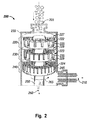
- Fig. 2 is a longitudinal cross-section view of a multi-stage high shear device, as employed in an embodiment of the system of Fig. 1 .
- the present methods and systems for the production of polyethylene and polypropylene, and their various copolymers, via heterogeneous liquid-solid, liquid-gas-solid, or gas-solid phase polymerization of the corresponding monomers and comonomers, in the presence of a suitable catalyst or initiator, employ an external high shear mechanical device to provide rapid contact and mixing of chemical ingredients in a controlled environment in the high shear mixer device, and a separate vessel or reactor.
- the high shear device reduces the mass transfer limitations on the reaction and thus increases the overall reaction rate.
- a reactor assembly that comprises an external high shear device or mixer as described herein makes possible decreased mass transfer limitations and thereby allows the reaction to more closely approach kinetic limitations. When reaction rates are accelerated, residence times may be decreased, thereby increasing obtainable throughput. Product yield may be increased as a result of the high shear system and process. Alternatively, if the product yield of an existing process is acceptable, decreasing the required residence time by incorporation of suitable high shear may allow for the use of lower temperatures and/or pressures than conventional processes. In some cases, it may be possible to reduce the reactor size while maintaining the same product yield.
- FIG. 1 is a process flow diagram showing an embodiment of a high shear system 1 for the production of polyethylene or polypropylene by catalyzed polymerization of the corresponding monomer.
- a similar method and system is employed to prepare polyethylene and/or polypropylene copolymers from the corresponding monomers and selected co-monomers.
- some suitable co-monomers for polymerization with ethylene or propylene include short-chain alpha-olefins such as I-butene, 1-hexene and 1-octene, vinyl acetate, and a various acrylates.
- the basic components of the system include external high shear mixing device (HSD) 40, vessel 10, and pump 5. As shown in Fig. 1 , the high shear device is located external to vessel/reactor 10. Each of these components is further described in more detail below.
- Line 21 is connected to pump 5 for introducing a liquid stream containing solvent and/or monomer.
- Line 13 connects pump 5 to HSD 40, and line 18 connects HSD 40 to vessel 10.
- Line 22 is connected to line 13 for introducing a slurry of finely divided catalyst suspended in a suitable solvent.
- Line 17 is connected to vessel 10 for removal of vent gas. Additional components or process steps may be incorporated between vessel 10 and HSD 40, or ahead of pump 5 or HSD 40, if desired.
- line 22 is instead configured for introducing a gaseous monomer stream into HSD 40, to form a gas-solid dispersion, as further described below.
- line 22 is configured to provide a particulate catalyst stream and line 13 is configured for carrying a solvent into HSD 40.
- HSD 40 also sometimes referred to as a high shear mixer, is configured for receiving an inlet stream via line 13.
- system 1 may be configured with more than one inlet line (not shown).
- HSD 40 may be configured for receiving the monomer and catalyst streams via separate inlet lines.
- HSD 40 is a mechanical device that utilizes one or more generators comprising a rotor/stator combination, each of which having a fixed gap between the stator and rotor.
- HSD 40 is configured in such a way that it is capable of producing a dispersion containing submicron- ( i.e ., less than one micron in diameter) and micron-sized particles (e.g ., catalyst particles) dispersed in a gas or liquid medium flowing through the mixer.
- HSD 40 is capable of highly dispersing a polymerization catalyst into a main liquid phase comprising monomer and solvent, with which it would normally be immiscible, at conditions such that at least a portion of the monomer reacts to produce a polymerization product stream.
- HSD 40 is configured to produce a dispersion containing submicron- and micron-sized bubbles (e.g ., gaseous monomer) dispersed in a liquid medium comprising solvent.
- HSD 40 is configured to produce a dispersion containing micron- and submicron-sized monomer bubbles and catalyst particles dispersed in a liquid solvent phase.
- the HSD 40 is configured for dispersing the catalyst particles into a main gaseous monomer phase.
- HSD 40 is configured for dispersing catalyst and gaseous monomer in a liquid solvent or in a solvent-monomer liquid phase, for certain heterogeneous liquid-gas-solid phase polymerization reactions.
- the high shear mixer comprises an enclosure or housing so that the pressure and temperature of the mixture may be controlled.
- High shear mixing devices are generally divided into three general classes, based upon their ability to mix fluids. Mixing is the process of reducing the size of particles or inhomogeneous species within the fluid. One metric for the degree or thoroughness of mixing is the energy density per unit volume that the mixing device generates to disrupt the fluid particles. The classes are distinguished based on delivered energy densities. Three classes of industrial mixers having sufficient energy density to consistently produce mixtures or dispersions with particle sizes in the range of submicron to 50 microns include homogenization valve systems, colloid mills and high speed mixers. In the first class of high energy devices, referred to as homogenization valve systems, fluid to be processed is pumped under very high pressure through a narrow-gap valve into a lower pressure environment. The pressure gradients across the valve and the resulting turbulence and cavitation act to break-up any particles in the fluid. These valve systems are most commonly used in milk homogenization and can yield average particle sizes in the 0-1 micron range.
- low energy devices At the opposite end of the energy density spectrum is the third class of devices referred to as low energy devices. These systems usually have paddles or fluid rotors that turn at high speed in a reservoir of fluid to be processed, which in many of the more common applications is a food product. These low energy systems are customarily used when average particle sizes of greater than 20 microns are acceptable in the processed fluid.
- colloid mills which are classified as intermediate energy devices.
- a typical colloid mill configuration includes a conical or disk rotor that is separated from a complementary, liquid-cooled stator by a closely-controlled rotor-stator gap, which is commonly between 0.0254-10.16 mm (0.001-0.40 inch).
- Rotors are usually driven by an electric motor through a direct drive or belt mechanism. As the rotor rotates at high rates, it pumps fluid between the outer surface of the rotor and the inner surface of the stator, and shear forces generated in the gap process the fluid.
- Many colloid mills with proper adjustment achieve average particle sizes of 0.1-25 microns in the processed fluid. These capabilities render colloid mills appropriate for a variety of applications including colloid and oil/water-based emulsion processing such as that required for cosmetics, mayonnaise, or silicone/silver amalgam formation, to roofing-tar mixing.
- Tip speed is the circumferential distance traveled by the tip of the rotor per unit of time. Tip speed is thus a function of the rotor diameter and the rotational frequency. Tip speed (in meters per minute, for example) may be calculated by multiplying the circumferential distance transcribed by the rotor tip, 2 ⁇ R, where R is the radius of the rotor (in meters, for example) times the frequency of revolution (in revolutions per minute).
- a colloid mill may have a tip speed in excess of 22.9 m/sec (4500 ft/min) and may exceed 40 m/sec (7900 ft/min).
- the term "high shear” refers to mechanical rotor stator devices (e.g., colloid mills or rotor/stator mixers) that are capable of tip speeds in excess of 5.1 m/sec. (1000 ft/min) and require an external mechanically driven power device to drive energy into the stream of materials to be reacted.
- a tip speed in excess of 22.9 m/sec (4500 ft/min) is achievable, and may exceed 40 m/sec (7900 ft/min).
- HSD 40 is capable of delivering at least 300 L/h with a power consumption of about 1.5 kW at a nominal tip speed of at least 22.9 m/sec (4500 ft/min).
- HSD 40 combines high tip speeds with a very small shear gap to produce significant shear on the material being processed. The amount of shear will be dependant on the viscosity of the fluid. Accordingly, a local region of elevated pressure and temperature is created at the tip of the rotor during operation of the high shear device. In some cases the locally elevated pressure is 1034.2 MPa (150,000 psi). In some cases the locally elevated temperature is 500°C. In some cases these local pressure and temperature elevations may persist for nano or pico seconds. In some embodiments, the energy expenditure of the high shear mixer is greater than 1000 W/m 3 . In embodiments, the energy expenditure of HSD 40 is in the range of from 3000 W/m 3 to 7500 W/m 3 .
- the shear rate is the tip speed divided by the shear gap width (minimal clearance between the rotor and stator).
- the shear rate generated in HSD 40 may be greater than 20,000 s -1 . In some embodiments the shear rate is at least 1,600,000 s -1 . In embodiments, the shear rate generated by HSD 40 is in the range of from 20,000 s -1 to 100,000 s -1 .
- the rotor tip speed is 40 m/sec (7900 ft/min) and the shear gap width is 0.0254 mm (0.001 inch), producing a shear rate of 1,600,000 s -1 .
- the rotor tip speed is 22.9 m/sec (4500 ft/min) and the shear gap width is 0.0254 mm (0.001 inch), producing a shear rate of 902,000 s -1 .
- HSD 40 comprises a colloid mill. Suitable colloidal mills are manufactured by IKA® Works, Inc. Wilmington, NC and APV North America, Inc. Wilmington, MA, for example. In some instances, HSD 40 comprises the Dispax Reactor® of IKA® Works, Inc. Several models are available having various inlet/outlet connections, horsepower, nominal tip speeds, output rpm, and nominal flow rate. Selection of a particular device will depend on specific throughput requirements for the intended application, and on the desired particle size in the outlet dispersion from the high shear mixer. In some embodiments, selection of the appropriate mixing tools (generators) within HSD 40 may allow for catalyst size reduction/increase in catalyst surface area.
- the high shear device comprises at least one revolving element that creates the mechanical force applied to the reactants.
- the high shear device comprises at least one stator and at least one rotor separated by a clearance.
- the rotors may be conical or disk shaped and may be separated from a complementary-shaped stator; both the rotor and stator may comprise a plurality of circumferentially-spaced teeth.
- the stator(s) are adjustable to obtain the desired gap between the rotor and the stator of each generator (rotor/stator set). Grooves in the rotor and/or stator may change directions in alternate stages for increased turbulence.
- Each generator may be driven by any suitable drive system configured for providing the necessary rotation.
- the minimum clearance between the stator and the rotor is in the range of from 0.0254 mm to 3.175 mm (0.001 inch to 0.125 inch). In certain embodiments, the minimum clearance between the stator and rotor is 1.524 mm (0.060 inch). In certain configurations, the minimum clearance between the rotor and stator is at least 1.778 mm (0.07 inch).
- the shear rate produced by the high shear mixer may vary with longitudinal position along the flow pathway. In some embodiments, the rotor is set to rotate at a speed commensurate with the diameter of the rotor and the desired tip speed. In some embodiments, the colloidal mill has a fixed clearance between the stator and rotor. Alternatively, the colloid mill has adjustable clearance.
- HSD 40 comprises a single stage dispersing chamber (i.e ., a single rotor/stator combination, a single generator).
- high shear device 40 is a multiple stage inline colloid mill and comprises a plurality of generators.
- HSD 40 comprises at least two generators.
- high shear device 40 comprises at least 3 high shear generators.
- high shear device 40 is a multistage mixer whereby the shear rate (which varies proportionately with tip speed and inversely with rotor/stator gap) varies with longitudinal position along the flow pathway, as further described herein below.
- each stage of the external high shear device has interchangeable mixing tools, offering flexibility.
- the DR 2000/4 Dispax Reactor® of IKA® Works, Inc. Wilmington, NC and APV North America, Inc. Wilmington, MA comprises a three stage dispersing module.
- This module may comprise up to three rotor/stator combinations (generators), with choice of fine, medium, coarse, and super-fine for each stage. This allows for creation of dispersions having a narrow distribution of the desired particle size.
- each of the stages is operated with super-fine generator.
- at least one of the generator sets has a rotor/stator minimum clearance of greater than 5.08 mm (0.20 inch).
- At least one of the generator sets has a minimum rotor/stator clearance of greater than 1.778 mm (0.07 inch).
- the rotors are 60 mm and the are stators 64 mm in diameter, providing a clearance of 4 mm.
- High shear device 200 is a dispersing device comprising three stages or rotor-stator combinations, 220, 230, and 240. Three rotor/stator sets or generators 220, 230, and 240 are aligned in series along drive input 250.
- the first generator 220 comprises rotor 222 and stator 227.
- the second generator 230 comprises rotor 223, and stator 228;
- the third generator 240 comprises rotor 224 and stator 229.
- the rotor is rotatably driven by input 250 and rotates, as indicated by arrow 265, about axis 260.
- Stator 227 is fixedly coupled to high shear device wall 255.
- Each generator has a shear gap which is the distance between the rotor and the stator.
- First generator 220 comprises a first shear gap 225; second generator 230 comprises a second shear gap 235; and third generator 240 comprises a third shear gap 245.
- shear gaps 225, 235, 245 are between 0.025 mm and 10.0 mm wide.
- the process comprises utilization of a high shear device 200 wherein the gaps 225, 235, 245 are between 0.5 mm and 2.5 mm. In certain instances the gap is maintained at 1.5 mm.
- the gaps 225, 235, 245 are different for generators 220, 230, 240.
- the gap 225 for the first generator 220 is greater than about the gap 235 for the second generator 230, which is in turn greater than about the gap 245 for the third generator.
- the generators of each stage may be interchangeable, offering flexibility.
- Generators 220, 230, and 240 may comprise a coarse, medium, fine, and super-fine characterization.
- Rotors 222, 223, and 224 and stators 227, 228, and 229 may be toothed designs. Each generator may comprise two or more sets of rotor-stator teeth.
- Rotors 222, 223, and 224 may comprise a number of rotor teeth circumferentially spaced about the circumference of each rotor.
- Stators 227, 228, and 229 may comprise a complementary number of stator teeth circumferentially spaced about the circumference of each stator.
- the inner diameter of the rotor is 11.8 cm.
- the outer diameter of the stator is 15.4 cm.
- each of three stages is operated with a super-fine generator, comprising a shear gap of between 0.025 mm and 3 mm.
- shear gap width may be selected for reduction in particle size and increase in particle surface area.
- the disperser is configured so that the shear rate will increase stepwise longitudinally along the direction of the flow.
- the IKA® model DR 2000/4 for example, comprises a belt drive, 4M generator, PTFE sealing ring, inlet flange 25.4 mm (1 inch) sanitary clamp, outlet flange 19 mm (3 ⁇ 4 inch) sanitary clamp, 2HP power, output speed of 7900 rpm, flow capacity (water) approximately 300-700 L/h (depending on generator), a tip speed of from 9.4-41 m/sec (1850 ft/min to 8070 ft/min).
- Vessel or reactor 10 is any type of vessel in which a multiphase reaction can be propagated to carry out the above-described conversion reaction(s).
- vessel 10 may be a tower reactor, a tubular reactor or multi-tubular reactor, or it may be a fixed bed reactor.
- vessel 10 may be a continuous or semi-continuous stirred tank reactor, or it may comprise one or more batch reactors arranged in series or in parallel.
- One or more line 15 may be connected to vessel 10 for introducing the initial solvent and monomer, or for injecting catalyst or other material.
- Vessel 10 may include one or more of the following items: stirring system, heating and/or cooling capabilities, pressure measurement instrumentation, temperature measurement instrumentation, one or more injection points, and level regulator (not shown), as are known in the art of reaction vessel design.
- a stirring system may include a motor driven mixer.
- a heating and/or cooling apparatus may comprise, for example, a heat exchanger.
- vessel 10 may serve primarily as a storage vessel in some cases. Although generally less desired, in some applications vessel 10 may be omitted, particularly if multiple high shear mixers/reactors are employed in series, as further described below.
- Line 16 is connected to vessel 10 for withdrawal or removal of the polyethylene, polypropylene or copolymer product.
- Heat Transfer Devices In addition to the above-mentioned heating/cooling capabilities of vessel 10, other external or internal heat transfer devices for heating or cooling a process stream are also contemplated in variations of the embodiments illustrated in Fig. 1 . Some suitable locations for one or more such heat transfer devices are between pump 5 and HSD 40, between HSD 40 and vessel 10, and between vessel 10 and pump 5 when system 1 is operated in multi-pass mode. Some non-limiting examples of such heat transfer devices are shell, tube, plate, and coil heat exchangers, as are known in the art.
- Pumps. Pump 5 is configured for either continuous or semi-continuous operation, and may be any suitable pumping device that is capable of providing greater than 203 kPa (2 atm) pressure, preferably greater than 3 atm pressure, to allow controlled flow through HSD 40 and system 1.
- a Roper Type 1 gear pump, Roper Pump Company (Commerce Georgia) Dayton Pressure Booster Pump Model 2P372E, Dayton Electric Co (Niles, IL) is one suitable pump.
- all contact parts of the pump comprise stainless steel. If corrosive substances are to be pumped it may be desirable to provide gold plated contact surfaces.
- pump 5 is capable of pressures greater than 2027 kPa (20 atm).
- one or more additional, high pressure pump may be included in the system illustrated in Fig. 1 .
- a booster pump which may be similar to pump 5
- a supplemental feed pump which may be similar to pump 5
- Line 24 connects vessel 10 to line 21 for introducing the initial liquid stream into HSD 40 via pump 5 and line 13, or for multi-pass operation, as further described herein below.
- a compressor type pump may be positioned between line 17 and HSD 40 for recycling gas from vessel 10 to an inlet of the high shear device.
- the monomer(s), any desired co-monomers, and solvent are first combined in vessel 10.
- the monomers and/or solvent may be initially introduced into vessel 10 via one or more feed line 15.
- the monomer solution contains 70% ethylene or propylene dissolved in a suitable organic solvent, such as, for example, hexane, cyclohexane, butane or pentane.
- the process may be operated in either continuous or semi-continuous flow mode, or it may be operated in batch mode.
- the contents of vessel 10 are maintained at a specified bulk reaction temperature using suitable heating and/or cooling capabilities (e.g ., cooling coils) and temperature measurement instrumentation. Pressure in the vessel may be monitored using suitable pressure measurement instrumentation, and the level of reactants in the vessel may be controlled using a level regulator (not shown), employing techniques that are known to those of skill in the art.
- the contents are stirred or circulated continuously or semi-continuously.
- Pump 5 is operated to pump the liquid stream (e.g., solvent or monomer-solvent solution) from reactor/vessel 10, via lines 24 and 21, and to build pressure and feed HSD 40, providing a controlled flow through line 13 and high shear mixer (HSD) 40, and throughout high shear system 1.
- pump 5 increases the pressure of the liquid stream to greater than 203 kPa (2 atm), preferably greater than 304 kPa (3 atm).
- pressures greater than 2027 kPa (20 atm) may be used to accelerate reactions, with the limiting factor being the pressure limitations of the selected pump 5 and high shear mixer 40.
- gaseous monomer may be introduced via a line similar to line 22 into a liquid stream flowing through line 13.
- the monomer-containing stream in line 13 comprises ethylene and/or polyethylene monomer, plus any desired co-monomers, dissolved in a suitable solvent, for the catalyzed polymerization of the monomers to form polyethylene or polypropylene, or a co-monomer thereof.
- the monomer-containing stream comprises solvent and gaseous monomer bubbles, with or without catalyst particles or initiator.
- Catalyst A slurry of finely divided catalyst suspended in a suitable solvent is combined with the monomer stream, or with a solvent-monomer stream, in line 13, by introduction through line 22.
- the catalyst slurry contains about 0.00001 to 0.1 percent Ziegler-Natta catalyst such as TiCl 4 /alkyl aluminum chloride.
- the catalyst is a metallocene catalyst.
- Metallocene compounds consist of two cyclopentadienyl anions (Cp) bound to a metal center in the oxidation state II, generally corresponding to the general formula (C 5 R 5 ) 2 M.
- Ziegler-Natta catalysts and metallocene catalysts are well known in the field of olefin polymerization.
- any other suitable olefin polymerization catalyst may be employed in the present methods.
- the selected mixing tools i.e ., rotor/stator sets or generators
- the monomer-containing liquid stream is continuously pumped into line 13 to form the high shear mixer feed stream. Additional solvent may be introduced into line 13, and in some embodiments, monomer and/or solvent is introduced independently into HSD 40.
- the actual ratio of the raw materials used is determined based on the desired selectivity and operating temperatures and pressures. In some embodiments, the pressure is kept high enough throughout system 1 to keep the monomer in solution.
- the terms "superficial pressure” and “superficial temperature” refer to the apparent, bulk, or measured pressure or temperature, respectively, in a vessel, conduit or other apparatus of the system.
- the actual temperatures and/or pressures at which the reactants make contact and react in the microenvironment of a transient cavity produced by the hydrodynamic forces of the high shear mixer may be quite different, as further discussed elsewhere herein.
- the catalyst and monomer liquid phase are mixed within HSD 40, which serves to create a fine dispersion of the catalyst in the monomer-containing liquid phase, which may also include initiator. In some embodiments it creates a fine mixture, emulsion or dispersion of the reactants, which may also include catalyst.
- the term "dispersion” refers to a liquefied mixture that contains two distinguishable substances (or phases) that will not readily mix and dissolve together.
- a dispersion comprises a continuous phase (or matrix), which holds therein discontinuous droplets, bubbles, and/or particles of the other phase or substance.
- dispersion may thus refer to foams comprising gas bubbles suspended in a liquid continuous phase, emulsions in which droplets of a first liquid are dispersed throughout a continuous phase comprising a second liquid with which the first liquid is immiscible, and continuous liquid phases throughout which solid particles are distributed.
- the term "dispersion” encompasses continuous liquid phases throughout which gas bubbles are distributed, continuous liquid phases throughout which solid particles (e.g., solid catalyst) are distributed, continuous phases of a first liquid throughout which droplets of a second liquid that is substantially insoluble in the continuous phase are distributed, and liquid phases throughout which any one or a combination of solid particles, immiscible liquid droplets, and gas bubbles are distributed.
- a dispersion can exist as a homogeneous mixture in some cases (e.g ., liquid/liquid phase), or as a heterogeneous mixture (e.g ., gas/liquid, solid/liquid, or gas/solid/liquid), depending on the nature of the materials selected for combination.
- a homogeneous mixture in some cases (e.g ., liquid/liquid phase), or as a heterogeneous mixture (e.g ., gas/liquid, solid/liquid, or gas/solid/liquid), depending on the nature of the materials selected for combination.
- the catalyst and monomer are highly dispersed such that nanoparticles and microparticles of the catalyst are formed for superior dissolution into solution and/or enhancement of reactant mixing.
- disperser IKA® model DR 2000/4 a high shear, three stage dispersing device configured with three rotors in combination with stators, aligned in series, is used to create the dispersion of dispersible catalyst in liquid medium comprising the monomers and any initiators ( i.e ., "the reactants").
- the rotor/stator sets may be configured as illustrated in Fig. 2 , for example.
- the direction of rotation of the generators may be opposite that shown by arrow 265 (e.g ., clockwise or counterclockwise about axis of rotation 260).
- the combined reactants entering the high shear mixer via line 13 proceed to a first stage rotor/stator combination having circumferentially spaced first stage shear openings.
- the direction of flow of the reactant stream entering inlet 205 corresponds to the axis of rotation 260.
- the coarse dispersion exiting the first stage enters the second rotor/stator stage, having second stage shear openings.
- the reduced particle-size dispersion emerging from the second stage enters the third stage rotor/stator combination having third stage shear openings.
- the shear rate increases stepwise longitudinally along the direction of the flow.
- the shear rate in the first rotor/stator stage is greater than the shear rate in subsequent stage(s).
- the shear rate is substantially constant along the direction of the flow, with the stage or stages being the same.
- the seal may be cooled using any suitable technique that is known in the art.
- the reactant stream flowing in line 13 may be used to cool the seal and in so doing be preheated as desired prior to entering the high shear mixer.
- the rotor of HSD 40 is set to rotate at a speed commensurate with the diameter of the rotor and the desired tip speed.
- the high shear mixer e.g ., colloid mill
- HSD 40 serves to intimately mix the catalyst and the liquid phase (i.e ., monomer or solvent, or both).
- the transport resistance of the reactants is reduced by operation of the high shear mixer such that the velocity of the reaction is increased by greater than a factor of 5.
- the velocity of the reaction is increased by at least a factor of 10.
- the velocity is increased by a factor in the range of about 10 to about 100 fold.
- HSD 40 delivers at least 300 L/h with a power consumption of 1.5 kW at a nominal tip speed of at least 22.9 m/sec (4500 ft/min), and which may exceed 40 m/sec (7900 ft/min).
- the localized temperature seen by the intimately mixed reactants is in excess of 500°C and at pressures in excess of 5000 kPa (500 kg/cm 2 ) under cavitation conditions.
- the high shear mixing results in dispersion of the catalyst in micron or submicron-sized particles ( i.e ., mean diameter less than one micron).
- the resultant dispersion has an average particle size less than about 1.5 ⁇ m.
- the mean bubble size is less than one micron in diameter.
- the dispersion exiting HSD 40 via line 18 comprises micron and/or submicron-sized particles.
- the mean particle size is in the range of 0.4 ⁇ m to 1.5 ⁇ m.
- the mean particle size is less than 400 nm, in the range of 200 nm to 400 nm, or is 100 nm in some cases.
- a nanodispersion is a dispersion of heterogeneous solid-liquid phases in which the sizes of the particles in the dispersed phase are less than 1000 nanometers (i.e., ⁇ 1 micron in diameter).
- a nanodispersion is sometimes also referred to herein as a "dispersion.”
- the nanodispersion is able to remain dispersed at atmospheric pressure for at least 15 minutes.
- the resulting nanodispersion exits HSD 40 via line 18 and feeds into vessel 10, as illustrated in Fig 1 , wherein polymerization occurs or continues to take place.
- the dispersion may be further processed prior to entering vessel 10. For example, further mixing in one or more successive high shear mixing devices, similar to HSD 40 with the same or different generator configurations, may be performed, before the process stream enters reactor/vessel 10.
- the polymerization reaction may take place to at least some extent without a catalyst or initiator, in most embodiments a catalyst or initiator is included.
- Some suitable types of catalyst are Ziegler-Natta catalysts and metallocene catalysts, as discussed above.
- another suitable olefin polymerization catalyst may be used.
- a chain transfer agent i.e ., hydrogen
- Hydrogen may be added at any point in the polymerization process where chain termination is desired.
- One or more such additives may be injected at line 13, line 18, or any other suitable point in the process, or as illustrated in the flow diagram shown in Fig. 1 .
- a heterogeneous reaction takes place in which the intimately mixed monomer and finely divided catalyst are in the form of a highly dispersed liquid.
- a significant portion of the chemical reaction may take place in HSD 40, with or without the presence of catalyst.
- reactor/vessel 10 may be used primarily for heating and separation of volatile reaction products (i.e ., vent gas) from the polymerization product.
- vessel 10 may serve as a primary reaction vessel where most of the polymer is produced in some embodiments.
- the process may be operated as a single pass or "once through” process in order to minimize subjecting the formed polymer to shearing, in which case vessel 10 may serve as the primary reaction vessel.
- Vessel/reactor 10 may be operated in either continuous or semi-continuous flow mode, or it may be operated in batch mode.
- the contents of vessel 10 may be maintained at a specified reaction temperature using heating and/or cooling capabilities (e.g., cooling coils) and temperature measurement instrumentation.
- Pressure in the vessel may be monitored using suitable pressure measurement instrumentation, and the level of reactants in the vessel may be controlled using a level regulator (not shown), employing techniques that are known to those of skill in the art.
- the contents are stirred continuously or semi-continuously.
- the bulk or global operating temperature of the reactants is desirably maintained below their flash points.
- the operating conditions of system 1 comprise a temperature in the range of from 20°C to 230°C. In some embodiments, the temperature is less than 200°C. In some embodiments, the temperature is in the range of from 160°C to 180°C. In specific embodiments, the reaction temperature in vessel 10, in particular, is in the range of from 155°C to 160°C. In some embodiments the process is operated at ambient temperature. In some embodiments, the reaction pressure in vessel 10 is in the range of from 203 kPa (2 atm) to 5573 kPa-6080 kPa (55-60 atm).
- reaction pressure is in the range of from 811 kPa to 1520 kPa (about 8 to about 15 atm). In some embodiments, the reaction pressure is less than 600 kPa (6 atm).
- the superior dissolution and/or dispersion provided by the external high shear mixing potentially allows a decrease in operating pressure while maintaining or even increasing reaction rate. Operating the polymerization process at decreased pressure potentially decreases wear of the materials constituting the reactors, the piping, and the mechanical parts of the plant, as well as the ancillary devices, in some embodiments of the high shear enhanced polymerization process.
- the polymerization product may be produced either continuously, semi-continuously or batch wise, as desired, and is removed from system 1 via product line 16.
- a plurality of reactor product lines 16 are used to remove the product.
- the vent gas may be further treated and vented, or its components may be recycled, as desired, using known techniques.
- Reaction product comprising polymer and dissolved, unconverted monomer exits reactor 10 by line 16.
- the product stream is further processed.
- the content of unconverted monomer in the product stream may be reduced using suitable techniques as are known.
- the polymer product may be used to manufacture any of a wide variety of commercial products. For instance, it may serve as the raw material for making packaging materials, vinyl flooring, plumbing pipe, clothing, upholstery or building materials.
- the system is configured for either single pass or multi-pass operation, wherein, after the initial preparation of the monomer-solvent solution in vessel 10 and commencement of the process, the output from line 16 of vessel 10 goes directly to recovery of the polymer product or to further processing.
- the dispersion and the initially formed polymer may be returned via lines 24 and 21, pump 5, and line 13, to HSD 40, for further dispersion and reaction.
- Additional catalyst slurry may be injected via line 22 into line 13, or it may be added directly into the high shear mixer (not shown), if needed. Additional solvent or monomer may be injected at line 13, as needed.
- two or more high shear devices like HSD 40 are aligned in series, and are used to further enhance the reaction. Their operation may be in either batch or continuous mode. In some instances in which a single pass or "once through" process is desired, the use of multiple high shear devices in series may also be advantageous. For instance, in some applications, where low density product containing shorter polymer chains is desired, the product may be recycled via lines 24 and 21, to pump 5, and through high shear mixer 40, before returning via line 18 to vessel 10. In some embodiments where multiple high shear devices are operated in series, vessel 10 may be omitted. When multiple high shear devices 40 are operated in series, additional reactant(s) may be injected into the inlet feed stream of each device. In some embodiments, multiple high shear devices 40 are operated in parallel, and the outlet dispersions therefrom are introduced into one or more vessel 10.
- the catalyst is not circulated through HSD 40, but is instead retained in vessel 10, where it is contacted by the premixed monome(s) exiting HSD 40 via line 18.
- a fixed bed reactor may be used as vessel 10, provided that it is not allowed to become blocked by polymer.
- solvent is pumped through line 21 and gaseous monomer is injected via line 22 into the flowing stream in line 13, which then flows into HSD 40 and is subjected to the high shear mixing as described above, to form a gas-liquid dispersion.
- the injection could be propylene or ethylene gas injected into a solvent medium like hexane and then polymerized with the use of a catalyst.
- the gas-liquid dispersion then contacts the catalyst in vessel 10, where polymerization occurs.
- submicron-sized bubbles dispersed in a liquid undergo movement primarily through Brownian motion effects.
- the bubbles in the product dispersion created by HSD 40 may have greater mobility through boundary layers of catalyst particles in vessel 10, thereby facilitating and accelerating the catalytic reaction through enhanced transport of reactants.
- catalyst is circulated through HSD 40 and gaseous monomer is introduced (via line 22) into a flowing stream of solvent in line 13, which may contain dissolved monomer.
- gaseous monomer is introduced (via line 22) into a flowing stream of solvent in line 13, which may contain dissolved monomer.
- a heterogeneous solid-gas-liquid reaction mixture exits HSD 40 via line 18.
- the polymerization reaction may occur in HSD 40, line 18, and/or vessel 10, or at any other point in system 1 where temperature and pressure conditions are favorable.
- a gas-solid heterogeneous phase polymerization reaction is carried out in HSD 40.
- solvent or liquid monomer is not fed into HSD 40, and instead a gaseous monomer stream flows through line 13 and catalyst particles are introduced via line 22.
- a dispersion of catalyst particles dispersed in gaseous monomer is produced in the high shear mixing device.
- This variation may be desired, for example, when is desirable for the gaseous monomers to oligomerize in a gas-solid reaction with the catalyst.
- a liquid-liquid homogeneous phase mixture of dissolved monomer in a suitable solvent e.g., hexane
- a suitable solvent e.g., hexane
- the polymerization reaction may occur in HSD 40, line 18, and/or vessel 10, or at any other point in system 1 where catalyst is present and the temperature and pressure conditions are favorable.
- the application of enhanced mixing of the reactants by HSD 40 potentially causes greater polymerization of the monomer in some embodiments of the process.
- the enhanced mixing potentiates an increase in throughput of the process stream.
- the high shear mixing device is incorporated into an established process, thereby enabling an increase in production ( i.e ., greater throughput).
- the superior dissolution and/or dispersion provided by external high shear mixing may allow in many cases a decrease in overall operating pressure while maintaining or even increasing the polymerization rate.
- the level or degree of high shear mixing is sufficient to increase rates of mass transfer and may also produce localized non-ideal conditions that enable reactions to occur that might not otherwise be expected to occur based on Gibbs free energy predictions.
- Localized non ideal conditions are believed to occur within the high shear device resulting in increased temperatures and pressures with the most significant increase believed to be in localized pressures.
- the increase in pressures and temperatures within the high shear device are instantaneous and localized and quickly revert back to bulk or average system conditions once exiting the high shear device.
- the high shear mixing device induces cavitation of sufficient intensity to dissociate one or more of the reactants into free radicals, which may intensify a chemical reaction or allow a reaction to take place at less stringent conditions than might otherwise be required. Cavitation may also increase rates of transport processes by producing local turbulence and liquid micro-circulation (acoustic streaming).
- An overview of the application of cavitation phenomenon in chemical/physical processing applications is provided by Gogate et al., "Cavitation: A technology on the horizon," Current Science 91 (No. 1): 35-46 (2006 ).
- the high shear mixing device of certain embodiments of the present system and methods is operated under what is believed to be cavitation conditions effective to dissociate the reactants into free radicals which then form the polymer.
- use of an above-described high shear process allows for greater catalyzed polymerization of monomer to polymerization product and/or an increase in throughput of the reactants.
- an external high shear mixing device is incorporated into an established process, thereby making possible an increase in production compared to the process operated without the high shear mixing of the reactants.
- a disclosed process or system makes possible the design of a smaller and/or less capital intensive process than previously possible without the incorporation of the external high shear mixing device.
- the application of a disclosed method potentially reduces operating costs/increases production from an existing process.
- the use of a disclosed method may reduce capital costs for the design of new polymerization processes.
- Still other potential benefits of some embodiments of the system and method for the production of polyethylene or polypropylene include, but are not limited to, faster cycle times, increased throughput, higher monomer conversion, reduced operating costs and/or reduced capital expense due to the possibility of designing smaller reactors and/or operating the polymerization process at lower temperature and/or pressure.
- a polymerization method is provided for the production of polypropylene, polyethylene, or co-polymers thereof, without the need for large volume reactors and without the need to recover substantial amounts of unconverted monomer.
Landscapes
- Chemical & Material Sciences (AREA)
- Chemical Kinetics & Catalysis (AREA)
- Health & Medical Sciences (AREA)
- Medicinal Chemistry (AREA)
- Polymers & Plastics (AREA)
- Organic Chemistry (AREA)
- Polymerisation Methods In General (AREA)
- Addition Polymer Or Copolymer, Post-Treatments, Or Chemical Modifications (AREA)
Claims (15)
- Verfahren zum Erzeugen eines Polymers, bei welchem eine Mischvorrichtung mit hoher Scherung bereitgestellt wird, wobei die Mischvorrichtung mit hoher Scherung mindestens einen Stator und mindestens einen Rotor aufweist, die durch einen Freiraum voneinander getrennt sind,
in der Mischvorrichtung mit hoher Scherung ein Gemisch mit hoher Scherung gebildet wird, welches ein Monomer und ein Lösungsmittel aufweist, wobei das Monomer ausgewählt ist aus der Gruppe bestehend aus Ethylen, Propylen, und Gemischen davon;
das Gemisch mit hoher Scherung von der Mischvorrichtung mit hoher Scherung in ein Reaktionsgefäß übertragen wird; und
das Gemisch mit hoher Scherung in dem Reaktionsbehälter Polymerisationsbedingungen ausgesetzt wird, im Zuge deren das Gemisch mit hoher Scherung einem Druck im Bereich von 203 kPa bis 6080 kPa und einer Temperatur im Bereich von 20 °C bis 230 °C ausgesetzt wird, um Polyethylen oder Polypropylen oder ein Copolymer davon zu bilden. - Verfahren gemäß Anspruch 1, bei welchem das Gemisch mit hoher Scherung Ethylen von Submikrongröße oder Propylengas enthaltene Blasen, die in dem Lösungsmittel enthalten sind, umfasst.
- Verfahren gemäß Anspruch 1 zum Erzeugen von Polyethylen, bei welchem das Gemisch mit hoher Scherung Ethylen und einen in einem Lösungsmittel dispergierten Polymerisationskatalysator aufweist, wobei das Gemisch mit hoher Scherung Teilchen mit Submikrongröße, die in einer flüssigen Phase dispergiert sind, umfasst, und wobei mindestens ein Teil des Ethylens unter Bildung von Polyethylen polymerisiert wird.
- Verfahren gemäß Anspruch 1 zum Erzeugen von Polypropylen, bei welchem das Gemisch mit hoher Scherung Propylen und einen in einem Lösungsmittel dispergierten Polymerisationskatalysator aufweist, wobei das Gemisch mit hoher Scherung Teilchen mit Submikrongröße, die in einer flüssigen Phase dispergiert sind, umfasst, und wobei mindestens ein Teil des Propylens unter Bildung von Polypropylen polymerisiert wird.
- Verfahren gemäß Anspruch 4, bei welchem das Gemisch mit hoher Scherung Propylengas enthaltende Blasen von Submikrongröße aufweist.
- Verfahren gemäß Anspruch 2 oder 5, bei welchem die Teilchen oder Blasen einen mittleren Durchmesser von weniger als 400 nm und vorzugsweise von nicht mehr als 100 nm haben.
- Verfahren gemäß Anspruch 1, 3 oder 4, bei welchem die Polymerisationsbedingungen einen Druck von weniger als 600 kPa und eine Temperatur von weniger als 200 °C umfassen.
- Verfahren gemäß Anspruch 1, bei welchem das Bilden des Gemisches mit hoher Scherung umfasst, dass das Monomer und das Lösungsmittel einer Scherungsrate von mehr als 20.000 s-1 ausgesetzt werden.
- Verfahren gemäß Anspruch 1, bei welchem der Rotor/Stator-Satz eine Spitze aufweist und wobei das Mischen mit hoher Scherung einen lokalen Druck an der Spitze von mindestens 1034 MPa erzeugt.
- Verfahren gemäß Anspruch 1, bei welchem das Gemisch mit hoher Scherung mindestens ein Comonomer umfasst, und das Polymerisationsprodukt entweder ein Polyethylencopolymer oder ein Polypropylencopolymer umfasst.
- Verfahren gemäß Anspruch 1, bei welchem das Bilden des Gemisches mit hoher Scherung einen Energieeintrag von mindestens 1000 W/m3 umfasst.
- System zum Erzeugen eines Polymers, versehen mit:mindestens einer Mischvorrichtung mit hoher Scherung, die einen Rotor/Stator-Satz mit einer Rotorspitze aufweist, wobei die Vorrichtung für einen Betrieb bei einer Durchflussrate von mindestens 300 l/h bei einer Geschwindigkeit der Spitze von mindestens 22,9 m/s ausgelegt ist, und wobei die Vorrichtung eine Nanodispersion erzeugt, die Teilchen oder Blasen mit einem mittleren Durchmesser von weniger als 1 µm dispergiert in einer Monomer enthaltenden flüssigen oder gasförmigen Phase umfasst;einer Pumpe, die zum Fördern eines unter Druck stehenden Flüssigkeitsstroms, welcher das Monomer umfasst, zu der Mischvorrichtung mit hoher Scherung ausgelegt ist; undeinem Behälter, der ausgelegt ist, die Nanodispersion von der Mischvorrichtung mit hoher Scherung zu erhalten und einen vorbestimmte Druck- und Temperaturwerte aufrechtzuerhalten.
- System gemäß Anspruch 12, bei welchem die Nanodispersion Teilchen oder Blasen mit einem mittleren Durchmesser von weniger als 400 nm aufweist.
- System gemäß einem der Ansprüche 12 bis 13, bei welchem die Mischvorrichtung mit hoher Scherung ausgelegt ist, einen Energieeintrag von mehr als 1000 W/m3 bereitzustellen.
- System gemäß einem der Ansprüche 12 bis 14, bei welchem der Behälter einen Turmreaktor, einen Röhrenreaktor, einen mehrrohrigen Reaktor, einen Tankreaktor oder einen Festbettreaktor aufweist.
Applications Claiming Priority (3)
| Application Number | Priority Date | Filing Date | Title |
|---|---|---|---|
| US94645607P | 2007-06-27 | 2007-06-27 | |
| US94645007P | 2007-06-27 | 2007-06-27 | |
| PCT/US2008/067830 WO2009002896A2 (en) | 2007-06-27 | 2008-06-23 | System and process for production of polyethylene and polypropylene |
Publications (3)
| Publication Number | Publication Date |
|---|---|
| EP2160418A2 EP2160418A2 (de) | 2010-03-10 |
| EP2160418A4 EP2160418A4 (de) | 2011-01-05 |
| EP2160418B1 true EP2160418B1 (de) | 2013-04-24 |
Family
ID=40186253
Family Applications (1)
| Application Number | Title | Priority Date | Filing Date |
|---|---|---|---|
| EP08771699.9A Not-in-force EP2160418B1 (de) | 2007-06-27 | 2008-06-23 | System und verfahren zur herstellung von polyethylen und polypropylen |
Country Status (6)
| Country | Link |
|---|---|
| US (2) | US8022153B2 (de) |
| EP (1) | EP2160418B1 (de) |
| CN (1) | CN101754987B (de) |
| CA (1) | CA2690787C (de) |
| EA (1) | EA024431B8 (de) |
| WO (1) | WO2009002896A2 (de) |
Families Citing this family (18)
| Publication number | Priority date | Publication date | Assignee | Title |
|---|---|---|---|---|
| US7491856B2 (en) | 2007-06-27 | 2009-02-17 | H R D Corporation | Method of making alkylene glycols |
| US8304584B2 (en) | 2007-06-27 | 2012-11-06 | H R D Corporation | Method of making alkylene glycols |
| US8282266B2 (en) | 2007-06-27 | 2012-10-09 | H R D Corporation | System and process for inhibitor injection |
| EP2691496A2 (de) | 2011-03-29 | 2014-02-05 | Fuelina, Inc. | Hybridkraftstoff und herstellungsverfahren dafür |
| EP2715030B1 (de) | 2011-05-24 | 2018-04-25 | Flexidrill Limited | Sinusförmige vibrierende bohrlochvorrichtung |
| US8771229B2 (en) | 2011-12-01 | 2014-07-08 | Picolife Technologies, Llc | Cartridge system for delivery of medicament |
| EA201491474A1 (ru) * | 2012-03-21 | 2015-05-29 | Эйч А Ди Корпорейшн | Устройство, система и способ преобразования первого материала во второй материал |
| US9096700B2 (en) | 2012-12-10 | 2015-08-04 | Exxonmobil Chemical Patents Inc. | Polymerization process for production of polymer |
| SG10201801623QA (en) * | 2014-09-02 | 2018-04-27 | Univation Tech Llc | Polyolefin production with chromium-based catalysts |
| EP2995369A1 (de) * | 2014-09-11 | 2016-03-16 | Eastern Macedonia & Thrace Institute of Technology | Vorrichtung zur Erzeugung und Verarbeitung von Nanoblasen |
| CA2969688A1 (en) | 2014-12-03 | 2016-06-09 | Drexel University | Direct incorporation of natural gas into hydrocarbon liquid fuels |
| CN112495310B (zh) * | 2019-09-14 | 2023-02-03 | 南京延长反应技术研究院有限公司 | 一种强化丙烯聚合的系统和工艺 |
| CN112500510A (zh) * | 2019-09-14 | 2021-03-16 | 南京延长反应技术研究院有限公司 | 基于溶液法制备聚乙烯的强化系统及工艺 |
| CN112500509B (zh) * | 2019-09-14 | 2023-03-10 | 南京延长反应技术研究院有限公司 | 一种强化乙烯聚合的系统和工艺 |
| CN112495320A (zh) * | 2019-09-14 | 2021-03-16 | 南京延长反应技术研究院有限公司 | 一种氯乙烯聚合物的制备系统及工艺 |
| CN111909293B (zh) * | 2020-06-17 | 2023-02-03 | 南京延长反应技术研究院有限公司 | 一种制备聚α烯烃的微界面强化反应系统及方法 |
| CN111875724B (zh) * | 2020-06-17 | 2021-08-27 | 南京延长反应技术研究院有限公司 | 一种溶液法制备聚乙烯的微界面强化反应系统及方法 |
| CN111892673A (zh) * | 2020-06-17 | 2020-11-06 | 南京延长反应技术研究院有限公司 | 一种制备聚丙烯的微界面强化反应系统及方法 |
Family Cites Families (48)
| Publication number | Priority date | Publication date | Assignee | Title |
|---|---|---|---|---|
| US2918460A (en) * | 1956-05-28 | 1959-12-22 | Koppers Co Inc | Polymerization process |
| US3062801A (en) * | 1960-06-01 | 1962-11-06 | Grace W R & Co | Propylene catalyst |
| US3166538A (en) * | 1961-01-13 | 1965-01-19 | Hercules Powder Co Ltd | Copolymerization process |
| US3296168A (en) * | 1962-07-11 | 1967-01-03 | Kativo S A | Continuous flow polymerization of vinyl acetate in emulsion |
| US3278510A (en) * | 1963-01-28 | 1966-10-11 | Union Carbide Corp | Stable catalyst systems for highly crystalline alpha olefin polymers |
| US3330818A (en) * | 1963-02-18 | 1967-07-11 | Monsanto Co | Elimination of fouling in ziegler polymerizations |
| NL130577C (de) * | 1964-07-17 | |||
| US3781320A (en) | 1971-02-09 | 1973-12-25 | Du Pont | Process for manufacture of organic isocyanates |
| US3887167A (en) * | 1971-02-09 | 1975-06-03 | Du Pont | Apparatus for manufacture of organic isocyanates |
| US4200614A (en) | 1978-02-17 | 1980-04-29 | National Distillers And Chemical Corporation | Turbine mixer |
| US4886905A (en) | 1981-01-30 | 1989-12-12 | Eastman Kodak Company | Preparation of ethyl acetate |
| JPS61172837A (ja) | 1985-01-28 | 1986-08-04 | Ihara Chem Ind Co Ltd | 核ハロゲン化置換ベンゼン類の製造方法 |
| JPS61183235A (ja) | 1985-02-12 | 1986-08-15 | Hodogaya Chem Co Ltd | クロロベンゼンの製造方法 |
| NL8702735A (nl) | 1987-11-17 | 1989-06-16 | Dorr Oliver Inc | Werkwijze voor het weken van granen met een nieuw enzympreparaat. |
| KR0161286B1 (ko) * | 1989-08-08 | 1999-01-15 | 엠. 윌킨스 | 중합방법과 반응기 |
| US4950831A (en) | 1989-09-28 | 1990-08-21 | Ethyl Corporation | Coupling process |
| US5009816A (en) | 1990-04-26 | 1991-04-23 | Union Carbide Industrial Gases Technology Corporation | Broad liquid level gas-liquid mixing operations |
| DE4106320C2 (de) | 1991-02-28 | 1994-05-26 | Burgert Burdosa | Polymerisationsvorrichtung |
| US5608017A (en) * | 1992-01-29 | 1997-03-04 | Tomoegawa Paper Co., Ltd. | Suspension polymerization method |
| US5264087A (en) | 1992-10-13 | 1993-11-23 | Eastman Kodak Company | Method for refining acetic anhydride by distillation |
| US5382358A (en) | 1993-03-24 | 1995-01-17 | Yeh; George C. | Apparatus for dissolved air floatation and similar gas-liquid contacting operations |
| US5451348A (en) | 1994-04-18 | 1995-09-19 | Praxair Technology, Inc. | Variable liquid level eductor/impeller gas-liquid mixing apparatus and process |
| DE4428018A1 (de) | 1994-08-08 | 1996-02-15 | Bayer Ag | Verfahren zur Herstellung von aromatischen Aminen |
| US6194625B1 (en) | 1994-09-30 | 2001-02-27 | Stratco, Inc. | Alkylation by controlling olefin ratios |
| KR19980702782A (ko) | 1995-03-09 | 1998-08-05 | 혼 마가렛 에이. | 녹말 액화 방법 |
| US5710355A (en) | 1996-06-10 | 1998-01-20 | Occidental Chemical Corporation | Method of making chlorobenzenes |
| CA2201224C (en) | 1997-03-27 | 2004-12-07 | Annette Lynn Burke | Dual shear mixing element |
| US6368367B1 (en) | 1999-07-07 | 2002-04-09 | The Lubrizol Corporation | Process and apparatus for making aqueous hydrocarbon fuel compositions, and aqueous hydrocarbon fuel composition |
| US6368366B1 (en) | 1999-07-07 | 2002-04-09 | The Lubrizol Corporation | Process and apparatus for making aqueous hydrocarbon fuel compositions, and aqueous hydrocarbon fuel composition |
| US6383237B1 (en) | 1999-07-07 | 2002-05-07 | Deborah A. Langer | Process and apparatus for making aqueous hydrocarbon fuel compositions, and aqueous hydrocarbon fuel compositions |
| EP0990638A1 (de) | 1998-10-01 | 2000-04-05 | Kvaerner Process Technology Limited | Verfahren |
| JP2000121353A (ja) | 1998-10-08 | 2000-04-28 | Canon Inc | 測距装置 |
| JP2000143706A (ja) | 1998-11-10 | 2000-05-26 | Mitsubishi Chemicals Corp | α−オレフィン重合体の製造方法 |
| US6251289B1 (en) | 1999-06-03 | 2001-06-26 | Grt, Inc. | Treatment of contaminated liquids with oxidizing gases and liquids |
| US6471392B1 (en) | 2001-03-07 | 2002-10-29 | Holl Technologies Company | Methods and apparatus for materials processing |
| US7538237B2 (en) | 1999-07-02 | 2009-05-26 | Kreido Laboratories | Process for high shear gas-liquid reactions |
| CZ292620B6 (cs) | 1999-10-14 | 2003-11-12 | Sulzer Chemtech Ltd. | Způsob výroby etylacetátu a zařízení k provádění tohoto způsobu |
| US6768021B2 (en) | 1999-12-22 | 2004-07-27 | Celanese International Corporation | Process improvement for continuous ethyl acetate production |
| JP2002003505A (ja) | 2000-06-20 | 2002-01-09 | Japan Polychem Corp | α−オレフィン重合体の製造方法 |
| JP4306943B2 (ja) | 2000-10-13 | 2009-08-05 | 電気化学工業株式会社 | エチレン−酢酸ビニル系共重合体エマルジョン組成物 |
| WO2004025260A2 (en) | 2002-09-11 | 2004-03-25 | Kreido Laboratories | Methods and apparatus for high-shear mixing and reacting of materials |
| US6787036B2 (en) | 2003-01-21 | 2004-09-07 | Fbc Technologies, Inc. | Method and apparatus for aerating wastewater |
| TW200504093A (en) | 2003-05-12 | 2005-02-01 | Dow Global Technologies Inc | Polymer composition and process to manufacture high molecular weight-high density polyethylene and film therefrom |
| EP1751082A2 (de) | 2004-04-21 | 2007-02-14 | Cargill, Incorporated | Verfahren zur erhöhung des durchsatzes von mais für die ölextraktion |
| CA2507897A1 (en) | 2004-06-07 | 2005-12-07 | Dover Chemical Corporation | High shear process for making metallic esters |
| US20060270769A1 (en) * | 2005-05-24 | 2006-11-30 | Shoaf Glenn L | Acrylic-modified alkyd hybrid latexes and their use as viscosity modifiers |
| US7276126B2 (en) | 2005-06-03 | 2007-10-02 | Tate And Lyle Ingredients Americas, Inc. | Production of enzyme-resistant starch by extrusion |
| WO2007023864A1 (ja) | 2005-08-24 | 2007-03-01 | Nsi Co., Ltd. | 泡発生装置 |
-
2008
- 2008-06-18 US US12/141,191 patent/US8022153B2/en not_active Expired - Fee Related
- 2008-06-23 CA CA2690787A patent/CA2690787C/en not_active Expired - Fee Related
- 2008-06-23 EP EP08771699.9A patent/EP2160418B1/de not_active Not-in-force
- 2008-06-23 CN CN2008800204410A patent/CN101754987B/zh not_active Expired - Fee Related
- 2008-06-23 EA EA200901532A patent/EA024431B8/ru not_active IP Right Cessation
- 2008-06-23 WO PCT/US2008/067830 patent/WO2009002896A2/en not_active Ceased
-
2011
- 2011-08-12 US US13/209,218 patent/US20110300024A1/en not_active Abandoned
Also Published As
| Publication number | Publication date |
|---|---|
| CA2690787C (en) | 2012-12-11 |
| WO2009002896A2 (en) | 2008-12-31 |
| EA024431B1 (ru) | 2016-09-30 |
| CA2690787A1 (en) | 2008-12-31 |
| EA024431B8 (ru) | 2017-01-30 |
| EP2160418A2 (de) | 2010-03-10 |
| US20090018286A1 (en) | 2009-01-15 |
| EA200901532A1 (ru) | 2010-04-30 |
| US8022153B2 (en) | 2011-09-20 |
| CN101754987B (zh) | 2012-06-13 |
| WO2009002896A3 (en) | 2009-02-19 |
| US20110300024A1 (en) | 2011-12-08 |
| CN101754987A (zh) | 2010-06-23 |
| EP2160418A4 (de) | 2011-01-05 |
Similar Documents
| Publication | Publication Date | Title |
|---|---|---|
| EP2160418B1 (de) | System und verfahren zur herstellung von polyethylen und polypropylen | |
| CA2693422C (en) | System and process for production of polyvinyl chloride | |
| US8133447B2 (en) | System for making linear alkylbenzenes | |
| US7888535B2 (en) | High shear process for the production of acetaldehyde | |
| US8771605B2 (en) | High shear system for the production of chlorobenzene | |
| US8383740B1 (en) | Horizontal agitator | |
| EP4424413A1 (de) | Schnellmischpolymerisierungsverfahren | |
| WO2021047049A1 (zh) | 一种强化乙烯聚合的系统和工艺 | |
| JP2007522319A (ja) | 反応装置中への反応物の噴射を最適化するための装置および方法 |
Legal Events
| Date | Code | Title | Description |
|---|---|---|---|
| PUAI | Public reference made under article 153(3) epc to a published international application that has entered the european phase |
Free format text: ORIGINAL CODE: 0009012 |
|
| 17P | Request for examination filed |
Effective date: 20091208 |
|
| AK | Designated contracting states |
Kind code of ref document: A2 Designated state(s): AT BE BG CH CY CZ DE DK EE ES FI FR GB GR HR HU IE IS IT LI LT LU LV MC MT NL NO PL PT RO SE SI SK TR |
|
| AX | Request for extension of the european patent |
Extension state: AL BA MK RS |
|
| A4 | Supplementary search report drawn up and despatched |
Effective date: 20101206 |
|
| 17Q | First examination report despatched |
Effective date: 20110915 |
|
| GRAP | Despatch of communication of intention to grant a patent |
Free format text: ORIGINAL CODE: EPIDOSNIGR1 |
|
| DAX | Request for extension of the european patent (deleted) | ||
| GRAP | Despatch of communication of intention to grant a patent |
Free format text: ORIGINAL CODE: EPIDOSNIGR1 |
|
| GRAS | Grant fee paid |
Free format text: ORIGINAL CODE: EPIDOSNIGR3 |
|
| GRAA | (expected) grant |
Free format text: ORIGINAL CODE: 0009210 |
|
| AK | Designated contracting states |
Kind code of ref document: B1 Designated state(s): AT BE BG CH CY CZ DE DK EE ES FI FR GB GR HR HU IE IS IT LI LT LU LV MC MT NL NO PL PT RO SE SI SK TR |
|
| REG | Reference to a national code |
Ref country code: GB Ref legal event code: FG4D |
|
| REG | Reference to a national code |
Ref country code: CH Ref legal event code: EP |
|
| REG | Reference to a national code |
Ref country code: AT Ref legal event code: REF Ref document number: 608617 Country of ref document: AT Kind code of ref document: T Effective date: 20130515 |
|
| REG | Reference to a national code |
Ref country code: IE Ref legal event code: FG4D |
|
| REG | Reference to a national code |
Ref country code: DE Ref legal event code: R096 Ref document number: 602008024108 Country of ref document: DE Effective date: 20130620 |
|
| REG | Reference to a national code |
Ref country code: AT Ref legal event code: MK05 Ref document number: 608617 Country of ref document: AT Kind code of ref document: T Effective date: 20130424 |
|
| REG | Reference to a national code |
Ref country code: LT Ref legal event code: MG4D |
|
| REG | Reference to a national code |
Ref country code: NL Ref legal event code: VDEP Effective date: 20130424 |
|
| PG25 | Lapsed in a contracting state [announced via postgrant information from national office to epo] |
Ref country code: ES Free format text: LAPSE BECAUSE OF FAILURE TO SUBMIT A TRANSLATION OF THE DESCRIPTION OR TO PAY THE FEE WITHIN THE PRESCRIBED TIME-LIMIT Effective date: 20130804 Ref country code: SI Free format text: LAPSE BECAUSE OF FAILURE TO SUBMIT A TRANSLATION OF THE DESCRIPTION OR TO PAY THE FEE WITHIN THE PRESCRIBED TIME-LIMIT Effective date: 20130424 Ref country code: PT Free format text: LAPSE BECAUSE OF FAILURE TO SUBMIT A TRANSLATION OF THE DESCRIPTION OR TO PAY THE FEE WITHIN THE PRESCRIBED TIME-LIMIT Effective date: 20130826 Ref country code: BE Free format text: LAPSE BECAUSE OF FAILURE TO SUBMIT A TRANSLATION OF THE DESCRIPTION OR TO PAY THE FEE WITHIN THE PRESCRIBED TIME-LIMIT Effective date: 20130424 Ref country code: LT Free format text: LAPSE BECAUSE OF FAILURE TO SUBMIT A TRANSLATION OF THE DESCRIPTION OR TO PAY THE FEE WITHIN THE PRESCRIBED TIME-LIMIT Effective date: 20130424 Ref country code: AT Free format text: LAPSE BECAUSE OF FAILURE TO SUBMIT A TRANSLATION OF THE DESCRIPTION OR TO PAY THE FEE WITHIN THE PRESCRIBED TIME-LIMIT Effective date: 20130424 Ref country code: SE Free format text: LAPSE BECAUSE OF FAILURE TO SUBMIT A TRANSLATION OF THE DESCRIPTION OR TO PAY THE FEE WITHIN THE PRESCRIBED TIME-LIMIT Effective date: 20130424 Ref country code: NO Free format text: LAPSE BECAUSE OF FAILURE TO SUBMIT A TRANSLATION OF THE DESCRIPTION OR TO PAY THE FEE WITHIN THE PRESCRIBED TIME-LIMIT Effective date: 20130724 Ref country code: FI Free format text: LAPSE BECAUSE OF FAILURE TO SUBMIT A TRANSLATION OF THE DESCRIPTION OR TO PAY THE FEE WITHIN THE PRESCRIBED TIME-LIMIT Effective date: 20130424 Ref country code: IS Free format text: LAPSE BECAUSE OF FAILURE TO SUBMIT A TRANSLATION OF THE DESCRIPTION OR TO PAY THE FEE WITHIN THE PRESCRIBED TIME-LIMIT Effective date: 20130824 Ref country code: GR Free format text: LAPSE BECAUSE OF FAILURE TO SUBMIT A TRANSLATION OF THE DESCRIPTION OR TO PAY THE FEE WITHIN THE PRESCRIBED TIME-LIMIT Effective date: 20130725 |
|
| PG25 | Lapsed in a contracting state [announced via postgrant information from national office to epo] |
Ref country code: PL Free format text: LAPSE BECAUSE OF FAILURE TO SUBMIT A TRANSLATION OF THE DESCRIPTION OR TO PAY THE FEE WITHIN THE PRESCRIBED TIME-LIMIT Effective date: 20130424 Ref country code: HR Free format text: LAPSE BECAUSE OF FAILURE TO SUBMIT A TRANSLATION OF THE DESCRIPTION OR TO PAY THE FEE WITHIN THE PRESCRIBED TIME-LIMIT Effective date: 20130424 Ref country code: LV Free format text: LAPSE BECAUSE OF FAILURE TO SUBMIT A TRANSLATION OF THE DESCRIPTION OR TO PAY THE FEE WITHIN THE PRESCRIBED TIME-LIMIT Effective date: 20130424 Ref country code: CY Free format text: LAPSE BECAUSE OF FAILURE TO SUBMIT A TRANSLATION OF THE DESCRIPTION OR TO PAY THE FEE WITHIN THE PRESCRIBED TIME-LIMIT Effective date: 20130424 Ref country code: BG Free format text: LAPSE BECAUSE OF FAILURE TO SUBMIT A TRANSLATION OF THE DESCRIPTION OR TO PAY THE FEE WITHIN THE PRESCRIBED TIME-LIMIT Effective date: 20130724 |
|
| PG25 | Lapsed in a contracting state [announced via postgrant information from national office to epo] |
Ref country code: CZ Free format text: LAPSE BECAUSE OF FAILURE TO SUBMIT A TRANSLATION OF THE DESCRIPTION OR TO PAY THE FEE WITHIN THE PRESCRIBED TIME-LIMIT Effective date: 20130424 Ref country code: DK Free format text: LAPSE BECAUSE OF FAILURE TO SUBMIT A TRANSLATION OF THE DESCRIPTION OR TO PAY THE FEE WITHIN THE PRESCRIBED TIME-LIMIT Effective date: 20130424 Ref country code: EE Free format text: LAPSE BECAUSE OF FAILURE TO SUBMIT A TRANSLATION OF THE DESCRIPTION OR TO PAY THE FEE WITHIN THE PRESCRIBED TIME-LIMIT Effective date: 20130424 Ref country code: MC Free format text: LAPSE BECAUSE OF FAILURE TO SUBMIT A TRANSLATION OF THE DESCRIPTION OR TO PAY THE FEE WITHIN THE PRESCRIBED TIME-LIMIT Effective date: 20130424 Ref country code: SK Free format text: LAPSE BECAUSE OF FAILURE TO SUBMIT A TRANSLATION OF THE DESCRIPTION OR TO PAY THE FEE WITHIN THE PRESCRIBED TIME-LIMIT Effective date: 20130424 |
|
| REG | Reference to a national code |
Ref country code: CH Ref legal event code: PL |
|
| PG25 | Lapsed in a contracting state [announced via postgrant information from national office to epo] |
Ref country code: NL Free format text: LAPSE BECAUSE OF FAILURE TO SUBMIT A TRANSLATION OF THE DESCRIPTION OR TO PAY THE FEE WITHIN THE PRESCRIBED TIME-LIMIT Effective date: 20130424 Ref country code: RO Free format text: LAPSE BECAUSE OF FAILURE TO SUBMIT A TRANSLATION OF THE DESCRIPTION OR TO PAY THE FEE WITHIN THE PRESCRIBED TIME-LIMIT Effective date: 20130424 Ref country code: IT Free format text: LAPSE BECAUSE OF FAILURE TO SUBMIT A TRANSLATION OF THE DESCRIPTION OR TO PAY THE FEE WITHIN THE PRESCRIBED TIME-LIMIT Effective date: 20130424 |
|
| PLBE | No opposition filed within time limit |
Free format text: ORIGINAL CODE: 0009261 |
|
| STAA | Information on the status of an ep patent application or granted ep patent |
Free format text: STATUS: NO OPPOSITION FILED WITHIN TIME LIMIT |
|
| REG | Reference to a national code |
Ref country code: IE Ref legal event code: MM4A |
|
| 26N | No opposition filed |
Effective date: 20140127 |
|
| PG25 | Lapsed in a contracting state [announced via postgrant information from national office to epo] |
Ref country code: LI Free format text: LAPSE BECAUSE OF NON-PAYMENT OF DUE FEES Effective date: 20130630 Ref country code: CH Free format text: LAPSE BECAUSE OF NON-PAYMENT OF DUE FEES Effective date: 20130630 Ref country code: IE Free format text: LAPSE BECAUSE OF NON-PAYMENT OF DUE FEES Effective date: 20130623 |
|
| REG | Reference to a national code |
Ref country code: DE Ref legal event code: R097 Ref document number: 602008024108 Country of ref document: DE Effective date: 20140127 |
|
| PG25 | Lapsed in a contracting state [announced via postgrant information from national office to epo] |
Ref country code: MT Free format text: LAPSE BECAUSE OF FAILURE TO SUBMIT A TRANSLATION OF THE DESCRIPTION OR TO PAY THE FEE WITHIN THE PRESCRIBED TIME-LIMIT Effective date: 20130424 |
|
| REG | Reference to a national code |
Ref country code: FR Ref legal event code: PLFP Year of fee payment: 8 |
|
| PG25 | Lapsed in a contracting state [announced via postgrant information from national office to epo] |
Ref country code: TR Free format text: LAPSE BECAUSE OF FAILURE TO SUBMIT A TRANSLATION OF THE DESCRIPTION OR TO PAY THE FEE WITHIN THE PRESCRIBED TIME-LIMIT Effective date: 20130424 |
|
| PG25 | Lapsed in a contracting state [announced via postgrant information from national office to epo] |
Ref country code: HU Free format text: LAPSE BECAUSE OF FAILURE TO SUBMIT A TRANSLATION OF THE DESCRIPTION OR TO PAY THE FEE WITHIN THE PRESCRIBED TIME-LIMIT; INVALID AB INITIO Effective date: 20080623 Ref country code: LU Free format text: LAPSE BECAUSE OF NON-PAYMENT OF DUE FEES Effective date: 20130623 |
|
| PGFP | Annual fee paid to national office [announced via postgrant information from national office to epo] |
Ref country code: DE Payment date: 20150629 Year of fee payment: 8 Ref country code: GB Payment date: 20150629 Year of fee payment: 8 |
|
| PGFP | Annual fee paid to national office [announced via postgrant information from national office to epo] |
Ref country code: FR Payment date: 20150617 Year of fee payment: 8 |
|
| REG | Reference to a national code |
Ref country code: DE Ref legal event code: R119 Ref document number: 602008024108 Country of ref document: DE |
|
| GBPC | Gb: european patent ceased through non-payment of renewal fee |
Effective date: 20160623 |
|
| REG | Reference to a national code |
Ref country code: FR Ref legal event code: ST Effective date: 20170228 |
|
| PG25 | Lapsed in a contracting state [announced via postgrant information from national office to epo] |
Ref country code: DE Free format text: LAPSE BECAUSE OF NON-PAYMENT OF DUE FEES Effective date: 20170103 Ref country code: FR Free format text: LAPSE BECAUSE OF NON-PAYMENT OF DUE FEES Effective date: 20160630 |
|
| PG25 | Lapsed in a contracting state [announced via postgrant information from national office to epo] |
Ref country code: GB Free format text: LAPSE BECAUSE OF NON-PAYMENT OF DUE FEES Effective date: 20160623 |