EP2159463B1 - Leitungsdurchführung mit Kombinationswerkstoff - Google Patents
Leitungsdurchführung mit Kombinationswerkstoff Download PDFInfo
- Publication number
- EP2159463B1 EP2159463B1 EP08015020A EP08015020A EP2159463B1 EP 2159463 B1 EP2159463 B1 EP 2159463B1 EP 08015020 A EP08015020 A EP 08015020A EP 08015020 A EP08015020 A EP 08015020A EP 2159463 B1 EP2159463 B1 EP 2159463B1
- Authority
- EP
- European Patent Office
- Prior art keywords
- gel
- conduit
- wall
- elastomer
- opening
- Prior art date
- Legal status (The legal status is an assumption and is not a legal conclusion. Google has not performed a legal analysis and makes no representation as to the accuracy of the status listed.)
- Not-in-force
Links
- 239000000463 material Substances 0.000 title claims abstract description 19
- 238000007789 sealing Methods 0.000 claims abstract description 35
- 229920001971 elastomer Polymers 0.000 claims description 61
- 239000000806 elastomer Substances 0.000 claims description 61
- 229920005862 polyol Polymers 0.000 claims description 13
- 238000000034 method Methods 0.000 claims description 6
- 239000012948 isocyanate Substances 0.000 claims description 4
- 150000002513 isocyanates Chemical class 0.000 claims description 4
- 239000012530 fluid Substances 0.000 claims description 3
- 238000004519 manufacturing process Methods 0.000 claims description 3
- 229920000642 polymer Polymers 0.000 claims description 3
- 125000001931 aliphatic group Chemical group 0.000 claims description 2
- 125000003118 aryl group Chemical group 0.000 claims description 2
- 239000000470 constituent Substances 0.000 claims 3
- 239000013590 bulk material Substances 0.000 claims 1
- 239000011248 coating agent Substances 0.000 claims 1
- 238000000576 coating method Methods 0.000 claims 1
- 239000004814 polyurethane Substances 0.000 abstract description 13
- 229920002635 polyurethane Polymers 0.000 abstract description 4
- 229920003225 polyurethane elastomer Polymers 0.000 abstract 2
- 230000001747 exhibiting effect Effects 0.000 abstract 1
- 239000000499 gel Substances 0.000 description 85
- 150000003077 polyols Chemical class 0.000 description 13
- 239000013536 elastomeric material Substances 0.000 description 7
- 239000007788 liquid Substances 0.000 description 7
- 239000004721 Polyphenylene oxide Substances 0.000 description 5
- 230000006835 compression Effects 0.000 description 5
- 238000007906 compression Methods 0.000 description 5
- 235000019589 hardness Nutrition 0.000 description 5
- 229920000570 polyether Polymers 0.000 description 5
- UPMLOUAZCHDJJD-UHFFFAOYSA-N 4,4'-Diphenylmethane Diisocyanate Chemical compound C1=CC(N=C=O)=CC=C1CC1=CC=C(N=C=O)C=C1 UPMLOUAZCHDJJD-UHFFFAOYSA-N 0.000 description 4
- GOOHAUXETOMSMM-UHFFFAOYSA-N Propylene oxide Chemical compound CC1CO1 GOOHAUXETOMSMM-UHFFFAOYSA-N 0.000 description 4
- 239000007789 gas Substances 0.000 description 3
- VGGSQFUCUMXWEO-UHFFFAOYSA-N Ethene Chemical compound C=C VGGSQFUCUMXWEO-UHFFFAOYSA-N 0.000 description 2
- 239000005977 Ethylene Substances 0.000 description 2
- IAYPIBMASNFSPL-UHFFFAOYSA-N Ethylene oxide Chemical compound C1CO1 IAYPIBMASNFSPL-UHFFFAOYSA-N 0.000 description 2
- 239000003795 chemical substances by application Substances 0.000 description 2
- 230000001419 dependent effect Effects 0.000 description 2
- 230000000694 effects Effects 0.000 description 2
- 238000005516 engineering process Methods 0.000 description 2
- 125000000524 functional group Chemical group 0.000 description 2
- 229910052751 metal Inorganic materials 0.000 description 2
- 239000002861 polymer material Substances 0.000 description 2
- 238000011282 treatment Methods 0.000 description 2
- IMNIMPAHZVJRPE-UHFFFAOYSA-N triethylenediamine Chemical compound C1CN2CCN1CC2 IMNIMPAHZVJRPE-UHFFFAOYSA-N 0.000 description 2
- XLYOFNOQVPJJNP-UHFFFAOYSA-N water Substances O XLYOFNOQVPJJNP-UHFFFAOYSA-N 0.000 description 2
- LYCAIKOWRPUZTN-UHFFFAOYSA-N Ethylene glycol Chemical compound OCCO LYCAIKOWRPUZTN-UHFFFAOYSA-N 0.000 description 1
- 229920005830 Polyurethane Foam Polymers 0.000 description 1
- 239000004809 Teflon Substances 0.000 description 1
- 229920006362 Teflon® Polymers 0.000 description 1
- UKLDJPRMSDWDSL-UHFFFAOYSA-L [dibutyl(dodecanoyloxy)stannyl] dodecanoate Chemical compound CCCCCCCCCCCC(=O)O[Sn](CCCC)(CCCC)OC(=O)CCCCCCCCCCC UKLDJPRMSDWDSL-UHFFFAOYSA-L 0.000 description 1
- 230000006978 adaptation Effects 0.000 description 1
- 239000002318 adhesion promoter Substances 0.000 description 1
- 230000001070 adhesive effect Effects 0.000 description 1
- 229910052782 aluminium Inorganic materials 0.000 description 1
- XAGFODPZIPBFFR-UHFFFAOYSA-N aluminium Chemical compound [Al] XAGFODPZIPBFFR-UHFFFAOYSA-N 0.000 description 1
- HIFVAOIJYDXIJG-UHFFFAOYSA-N benzylbenzene;isocyanic acid Chemical class N=C=O.N=C=O.C=1C=CC=CC=1CC1=CC=CC=C1 HIFVAOIJYDXIJG-UHFFFAOYSA-N 0.000 description 1
- 229910052797 bismuth Inorganic materials 0.000 description 1
- JCXGWMGPZLAOME-UHFFFAOYSA-N bismuth atom Chemical compound [Bi] JCXGWMGPZLAOME-UHFFFAOYSA-N 0.000 description 1
- CDQSJQSWAWPGKG-UHFFFAOYSA-N butane-1,1-diol Chemical compound CCCC(O)O CDQSJQSWAWPGKG-UHFFFAOYSA-N 0.000 description 1
- 238000005266 casting Methods 0.000 description 1
- 239000003054 catalyst Substances 0.000 description 1
- 239000002131 composite material Substances 0.000 description 1
- 150000001875 compounds Chemical class 0.000 description 1
- 238000003851 corona treatment Methods 0.000 description 1
- 239000012975 dibutyltin dilaurate Substances 0.000 description 1
- 238000004043 dyeing Methods 0.000 description 1
- 239000000835 fiber Substances 0.000 description 1
- 238000005187 foaming Methods 0.000 description 1
- 239000011888 foil Substances 0.000 description 1
- 239000012634 fragment Substances 0.000 description 1
- 238000007373 indentation Methods 0.000 description 1
- 238000009434 installation Methods 0.000 description 1
- 230000001788 irregular Effects 0.000 description 1
- IQPQWNKOIGAROB-UHFFFAOYSA-N isocyanate group Chemical group [N-]=C=O IQPQWNKOIGAROB-UHFFFAOYSA-N 0.000 description 1
- 239000012528 membrane Substances 0.000 description 1
- 239000002184 metal Substances 0.000 description 1
- 239000007769 metal material Substances 0.000 description 1
- 239000000203 mixture Substances 0.000 description 1
- 238000009832 plasma treatment Methods 0.000 description 1
- 239000004033 plastic Substances 0.000 description 1
- 229920003023 plastic Polymers 0.000 description 1
- 239000004014 plasticizer Substances 0.000 description 1
- 229920006395 saturated elastomer Polymers 0.000 description 1
- 239000000126 substance Substances 0.000 description 1
- 230000008961 swelling Effects 0.000 description 1
Images


Classifications
-
- F—MECHANICAL ENGINEERING; LIGHTING; HEATING; WEAPONS; BLASTING
- F16—ENGINEERING ELEMENTS AND UNITS; GENERAL MEASURES FOR PRODUCING AND MAINTAINING EFFECTIVE FUNCTIONING OF MACHINES OR INSTALLATIONS; THERMAL INSULATION IN GENERAL
- F16L—PIPES; JOINTS OR FITTINGS FOR PIPES; SUPPORTS FOR PIPES, CABLES OR PROTECTIVE TUBING; MEANS FOR THERMAL INSULATION IN GENERAL
- F16L5/00—Devices for use where pipes, cables or protective tubing pass through walls or partitions
- F16L5/02—Sealing
- F16L5/10—Sealing by using sealing rings or sleeves only
-
- H—ELECTRICITY
- H02—GENERATION; CONVERSION OR DISTRIBUTION OF ELECTRIC POWER
- H02G—INSTALLATION OF ELECTRIC CABLES OR LINES, OR OF COMBINED OPTICAL AND ELECTRIC CABLES OR LINES
- H02G3/00—Installations of electric cables or lines or protective tubing therefor in or on buildings, equivalent structures or vehicles
- H02G3/22—Installations of cables or lines through walls, floors or ceilings, e.g. into buildings
Definitions
- This invention relates to a conduit bushing for building a sealing closure in a wall opening which is penetrated by a conduit or is to be penetrated.
- cables are routed through walls, in many cases the opening provided for this purpose must be sealed against liquids and / or gases, for which so-called cable bushings are used.
- This can affect a wide variety of walls, such as building walls. Cable bushings are also known for the dense passage of cables through walls other than building walls, such as ships etc.
- a wall in the sense of the invention is thus a dense boundary of a range.
- interior or exterior walls are included, for example, of air, water, space or land vehicles, machinery or technical equipment, the seal may affect liquids and / or gases.
- the line is preferably a power, gas, water, heat, telecommunications or other signal or data line.
- the line can be rigid or flexible.
- the invention also relates to closed cable bushings, which close only the option for a Kirs Stütt forming wall openings; If, therefore, there is talk of a pipe passing through the openings, this may also refer to a future pipe which is optional in this sense.
- the elastomer elements of conventional cable bushings which are responsible for the sealing properties must fit relatively accurately with regard to the pipe dimensions and also the wall opening dimensions, because only limited geometrical tolerances can be bridged in the compression or expansion of elastomers if perfect sealing properties must be ensured.
- sealing systems of elastomers require a certain surface quality of the sealing surface to be brought into contact.
- the invention is intended to specify an improved cable feedthrough which is particularly efficient with regard to the bridging of geometric tolerances and / or the sealing properties in problematic surfaces.
- the invention is directed to a cable bushing for building a sealing closure of an opening penetrated by a line in a wall with a PU elastomer body and a PU gel body, which have an intimate inseparable material connection, wherein the gel body to bear against a sealing surface of the wall and / or the line is designed.
- the invention is further directed to a designed with such a bushing technical housing and to preferred uses of the cable bushing and finally to a method for producing the line feedthrough.
- the basic idea of the invention consists in the combination of a previously known elastomer body with a gel and in the use of specifically a polyurethane-based elastomer (PU) and at the same time also a polyurethane-based gel.
- PU polyurethane-based elastomer
- Extensive testing has shown that this combination make a very good material connection, which is so intimate that it can not be separated in practice. In concrete terms, this means that if the mechanical stresses are too great, the gel body will be destroyed rather than the gel body completely becoming detached from the elastomer body, ie the material connection itself will be destroyed again.
- This property plays an important role for the applications in the line bushing area, because considerable mechanical stresses can occur, in particular, when plugging in cables.
- the gel body should be applied to at least one sealing surface to be sealed, d. H. to a sealing surface of the wall and / or a sealing surface of the line, but preferably to a line sealing surface.
- the elastomeric body should in turn be designed to rest against the wall sealing surface.
- This flat or three-dimensionally formed layers, fibers or spherical disperse composite structures can be constructed, although for the mentioned sealing surface, a gel body surface should be provided. In all cases, the material combination between an elastomer and a gel opens up material properties that were not achievable with prior art single-ended elastomers.
- the elastomer body provides good mechanical strength and dimensional stability and high restoring forces and high average Shorehärten while the gel is a particularly good flow, especially at low temperatures, and a very good conformability even on irregular surfaces with indentations, cracks, notches and similar actually problematic structural features shows
- the PU gel according to the invention acts almost like a liquid even at very low Vertormungs claim and therefore lays particularly well in surface irregularities into it. The resulting sealing qualities are only possible with elastomers at very high pressure forces or not at all.
- the elastomeric body in turn can give space to the described deformation of the gel and thereby generate corresponding restoring forces.
- the gel behaves approximately like a Newtonian fluid, so it is essentially incompressible, and thus quite capable of transmitting forces.
- the gel after compression shows a very good resilience, so that the line feedthrough after removal of the line substantially the same geometric sealing area as before, at least shows no significant changes.
- Elastomers on the other hand, often suffer from the problem of not providing sufficient resilience; they show a so-called compression set.
- the gel body should be used for the sealing installation, in particular on the line.
- the elastomer body preferably supports the gel body and in a certain way forms a positive connection.
- the elastomeric body encloses and holds the gel body on both sides in at least one direction and thus transmits at least part of the basic mechanical stability of the elastomeric body to the gel body.
- this is the case not only in one direction, but in two directions, and more preferably in all directions in a plane, as in the embodiments. In one embodiment, this also applies to a third direction perpendicular to this plane.
- the so-called positive locking should not take the place of the actual material connection, so do not compensate for insufficient adhesive properties, but with the elastomeric body that applies the greater restoring forces, so to speak provide a mechanical framework around the gel around.
- the gel body is completely enclosed in two mutually perpendicular directions and particularly preferably in all directions of this plane of the elastomeric body, the gel body is thus arranged in an opening of the elastomer body and in this for sealingly encompassing the line to be performed is provided.
- the gel body can be completely provided within an opening passing through the elastomer body from its front side to its rear side and arranged between the end edges of the elastomer body which terminate on both sides of this opening. In other words, he does not stand outside the opening.
- the elastomer component can be set by appropriate dimensioning under a certain bias, such as by having over the wall opening an oversize or compared to the line an undersize (the latter, taking into account the gel body). This gives advantageous elastomeric pressure forces for the sealing properties.
- the combination material is used for closing passage openings, through which a long body, for example a cable, a pipe, a rod or the like is guided.
- the elastomeric material preferably forming the outer surface may then form a seal with the surfaces surrounding it, defining them, for example by being pressed from inside to outside by a radially acting force.
- the preferably inside, namely in an elastomeric material through the opening arranged gel surrounds in a sealing manner the long body.
- the gel can be designed such that it in turn has an opening for the long body, wherein the opening preferably has a smaller diameter than the outer diameter of the long body. If the long body is then pushed through the opening in the gel, it pushes the gel outwards.
- the gel behaves like a Newtonian liquid, it is essentially not compressed, but moved outward, pushing the elastomeric material outward.
- This outwardly directed force acting on the elastomeric material can be used to push the elastomeric material against the surfaces of the wall opening and thus develop a sealing effect by adhesion.
- the device acts as an elastomer to the outside.
- the elastomeric material may additionally take over the function of the mechanical Abstutzung the long body. At the same time, the restoring forces of the stretched elastomer material can cause the gel to abut the long body well.
- the elastomer body is in this case completely closed by the gel body, ie the gel body must first be opened when piercing a conduit.
- an opening is already present in the gel body, which can still be increased when performing the line.
- the gel body is not particularly hijacked, so it also has substantially the same material properties on the surface as in the volume, and is also not surface-coated in any other way, such as with a foil lining o. ⁇ . Rather, the inherent gel properties should also come to light on the surface and they should not fundamentally change with substantial deformations of the gel body, such as when a film or skin would stretch or tear.
- line bushings which take into account a plurality of lines. This can be done with the same gel body; but preferred is a design with a corresponding plurality of gel bodies, which are all held by the same elastomeric body. With regard to the exemplary embodiments, these have to be imagined side by side in a plurality, as it were, connected in parallel, the elastomeric body being of uniform design.
- a very particularly preferred application of the invention is in technical housings, in particular for electrical or electronic devices.
- the invention can serve for sealing passages passing through the housing wall.
- the invention is thus also directed to a corresponding housing. Further preferred uses have already been mentioned.
- a housing components are also understood housing from the field of handling of guided in pipes fluids, such as pump housing, pump shafts or the like.
- the invention is also directed to a method for producing the line feedthrough, in which the described intimate and inseparable Material connection is made.
- the gel can be brought to the elastomer body, for example, in a state which is not yet completely cross-linked, for example, to be poured on, in order then to further crosslink in this contact.
- another possibility is to first produce a gel body and then to form the elastomer body around the gel body, for example by, in particular, pressure-free casting or a foaming process.
- PU foams are preferred in terms of the elastomer body.
- a gel is understood to mean a chemically or physically linked polymer network which has swollen in a medium. It consists of at least two components that are more or less continuously distributed in an existing volume. In a preferred embodiment of this invention, the two components are polymer chemically identical. Through the use of polyols with a large number of functionalities and non-saturated side chains, the latter can act as the source medium. For example, two to three out of six existing functional groups may be reacted, leaving three to four. The polyols together with the isocyanate form a polymeric basic structure, the unreacted side chains forming an integrated plasticizer or the swelling medium.
- the gel can have a high elasticity and strength or toughness or tear resistance, so that when piercing the gel body or an opening therein with a line, the line is enclosed, but not too large extent or not at all fragments of the gel to be towed ,
- polyether polyols As preferred polyol components and isocyanate components for the PU material of the gel body and the PU material of the elastomer body, it is possible to use, for example, polyether polyols on the one hand and aliphatic or aromatic di- or oligoisocyanates on the other hand.
- highly functional polyether polyols for example those having a functionality number between 3 and 6, are preferred.
- the gel it can be achieved via the metered addition of the isocyanate component that only a portion of the available functional groups react and polyol side chains remain mobile.
- FIG. 1 is a part of a cable bushing 11 according to the invention shown in a sectional view. Shown are a part of the elastomer body 12 of the conduit bushing 11 and the gel body 13. Between the elastomer body 12 and the Geiisme 13 is at a contact surface 14 an intimate connection. This intimate connection is represented by the dotted lines. The gel body 13 is additionally supported with an edge region 14 in a recess of the elastomer body 12.
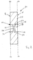
- FIG. 2 shows a cable bushing 21 for sealing a (not shown) cable or pipe outlet of a (also not shown) component housing. Shown are the elastomeric body 22 and the gel body 23. At the contact surface 24 between the elastomer body 22 and the gel body 23 is an intimate connection, but without a recess. The elastomeric body 22 has an opening 25.
- the opening 25 leads from the front side V of the elastomeric body 22 to the rear side R thereof and is delimited by walls which form a circumferential end edge 26, 27 on the front side and the rear side, respectively, so that an opening space is formed which extends from the plane E1, in which the end edge 26 is located on the front side V, to the plane E2, in which the end edge 27 is located on the rear side R, wherein the gel body 23 is arranged in this opening space.
- an opening 28 for passing a long body, such as a cable or a pipe is provided.
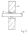
- FIG. 3 shows the device after FIG. 2
- the long body 29 has an outer diameter which is greater than the diameter of the opening 28.
- the inserted long body 29 causes the gel of the gel body 23 to be perpendicular to the longitudinal axis of the long body, ie in the direction of the Elastomer body 22 pushed away.
- the elastomer body 22 gives way to this movement of the gel body 23 elastically.
- the gel body 23 thus pushes the elastomer body 22 outwards so that it is pressed against the wall of the cable and tube outlet (not shown) on its outer circumference.
- a sealing effect is generated by adhesion.
- the elastomer body 22 exerts a restoring force on the gel body 23, which, together with its own restoring force of the gel body 23, results in a sealing engagement of the gel body 23 on the outer circumference of the long body 29.
- FIG. 4 shows a device 30 for sealing a cable or pipe outlet 31.
- the device 30 has an elastomer body 32 with two gel bodies 33, 34.
- the gel body 33 is disposed in an opening 35 of the elastomer body 32 and the gel body 34 in an opening 36 of the elastomer body 32.
- 34 cables 37, 38, 39 are guided, with which the corresponding openings in the gel bodies 33, 34 were first generated.
- the cables 37, 38, 39 were pushed axially by force application through the gel bodies 33, 34.
- the elastomer body 32 has an outer contour which substantially corresponds to the dimensions of the cable or pipe outlet 31. As a result, the elastomer body 32 closes the cable or pipe outlet 31.
- the cable bushings described above are made of the material technology as follows.
- the polyol component is reacted with 13.5 parts by weight of a modified diphenylmethane diisocyanate ("MDI", so-called polymeric MDI, although strictly speaking it is not MDI) having an NCO content of 12%.
- MDI modified diphenylmethane diisocyanate
- the two components are mixed together by means of a conventional low-pressure machine and then introduced into an open mold.
- the aluminum mold encloses a thick-walled hollow cylinder, which is filled by the liquid reacting mass.
- the walls of the mold are coated with a release-friendly plastic (teflon). After about 5 minutes, the finished gel body is removed.
- the soft gel has a Shore 000 hardness of about 65. It is highly elastic with an elongation at break of more than 300%. Shore 000 hardnesses of at least 50, 55 and more preferably at least 60 and of at most 70 and more preferably not more than 65 are advantageous.
- the gel is placed in a mold and forms the inner space of a second cylindrical shape.
- the second form is partially closed.
- a liquid reactive elastomer mixture is mixed with a second low pressure machine and poured into the second mold to make the elastomeric body.
- the polyol component consists of 100 parts by weight of a trifuntionellen polyether polyol having an OH number of 28, 7 parts by weight of butanediol, 1 part by weight of triethylenediamine (33% in monoethylene glycol) and 0.2 parts by weight of dibutyltin dilaurate.
- the isocyanate component which is mixed with the polyol component is a difunctional modified MDI having an NCO content of 23%.
- the resulting elastomer has a Shore A hardness of about 60. Shore A hardnesses of at least 45, 50, 55, and more preferably at least 60, and at most 70, and most preferably at most 65 are advantageous.
- the cable bushing according to the invention allows a very good adaptation to different cable diameters, without any risk of pressure tightness due to differently pronounced strains of pure elastomer membranes or mechanical strength exist or to avoid such difficulties elastomeric parts would have to be replaced line-dependent.
- the elastomer body takes over the seal to the outside to the wall opening or its reveal, such as in an introduction plate of a device housing, and serves for mechanical Abstutzung of the line.
- the gel body serves to adapt the diameter to the actually performed line and to seal against the line. It expands as needed, relying on the elastomeric body, which can expand if necessary. After the line has been pulled in, the restoring forces of the elastomer body, distributed by the attached gel body, act on the line, such as the cable.
- the gel used recovers almost completely after compression, so that the cable leadthrough after removal of the line maintains its sealing area.
- the conduit may have an outer diameter of 30 mm at a previous opening in the gel of only 10 mm.
- the cables only have to be inserted.
- the embodiments may also be designed to be divisible, for example in two halves. The low Shore hardness of the PUR gel allows a corresponding expansion. Introduced cables could be moved even at temperatures of - 20 ° C, without leaking occurred.
Landscapes
- Engineering & Computer Science (AREA)
- General Engineering & Computer Science (AREA)
- Architecture (AREA)
- Civil Engineering (AREA)
- Structural Engineering (AREA)
- Mechanical Engineering (AREA)
- Sealing Material Composition (AREA)
- Insulating Bodies (AREA)
- Compositions Of Macromolecular Compounds (AREA)
- Insulated Conductors (AREA)
- Installation Of Indoor Wiring (AREA)
- Insulators (AREA)
- Cable Accessories (AREA)
- External Artificial Organs (AREA)
- Superconductors And Manufacturing Methods Therefor (AREA)
Description
- Diese Erfindung bezieht sich auf eine Leitungsdurchführung zum Aufbauen eines dichtenden Verschlusses in einer Wandöffnung, die von einer Leitung durchsetzt ist oder durchsetzt werden soll.
- Eine solche Leitungsdurchführung ist in
DE 20 2007 002809 U1 offenbart. - Wenn Leitungen durch Wände geführt werden, muss in vielen Fällen die dafür vorgesehene Öffnung gegen Flüssigkeiten und/oder Gase abgedichtet werden, wofür sog. Leitungsdurchführungen eingesetzt werden. Dies kann unterschiedlichste Wände betreffen, etwa Gebäudewände. Leitungsdurchführungen sind zudem auch für das dichte Hindurchführen von Leitungen durch andere Wände als Gebäudewände bekannt, etwa bei Schiffen etc. Eine Wand im Sinne der Erfindung ist also eine dichte Begrenzung eines Bereichs. Dabei sind Innen- oder Außenwände beispielsweise von Luft-, Wasser-, Raum- oder Landfahrzeugen, von Maschinen oder technischen Anlagen inbegriffen, wobei die Abdichtung Flüssigkeiten und/oder Gase betreffen kann.
- Es kann sich aber auch um Gehäusewände von technischen Geräten handeln, etwa aus Metall oder Polymermaterialien. Die Leitung ist vorzugsweise eine Strom-, Gas-, Wasser-, Wärrne-, Telekommunikations- oder anderweitige Signal- oder Datenleitung. Die Leitung kann starr oder flexibel sein.
- Die Erfindung bezieht sich dabei auch auf geschlossene Leitungsdurchführungen, die lediglich die Option für einen Leitungsdurchtütt bildende Wandöffnungen verschließen; wenn hier also von einer die Öffnungen durchsetzenden Leitung die Rede ist, kann sich dies auch auf eine in diesem Sinn optionale zukünftige Leitung beziehen.
- Konventionellerweise kommen in Leitungsdurchführungen Elastomere zum Einsatz, die entweder über eine Verpressung oder aber über eine Elastomerdehnung in eine dichtende Anlage mit Dichtflächen seitens der durchzuführenden Leitung und auch seitens der Wandöffnung gebracht werden. In diesem Zusammenhang wird übrigens im Folgenden nur noch von der Leitung und der Wandöffnung gesprochen, obwohl beispielsweise auch Rohrstücke abgedichtet werden können, die ihrerseits die Leitung aufnehmen, hier aber in dem allgemeinen Begriff der "Leitung" beinhaltet sein sollen. Auch können in die Wandöffnung noch weitere Elemente eingesetzt werden, die eine eigenständige Laibung aufbauen, insbesondere Metallrahmen. Wenn von Dichtflächen der Wandöffnung bzw. von der Wandöffnung selbst die Rede ist, sollen auch solche Fälle inbegriffen sein. Bevorzugt richtet sich die Erfindung allerdings auf Leitungsdurchführungen, die die eigentliche Leitung selbst aufnehmen und dichten bzw. in die Wandöffnung selbst direkt eingesetzt sind.
- Die für die Dichteigenschaften verantwordichen Elastomerelemente von konventionellen Leitungsdurchführungen müssen hinsichtlich der Leitungsmaße und auch der Wandöffnungsmaße relativ genau passen, weil bei der Verpressung oder dem Dehnen von Elastomeren nur begrenzte geometrische Toleranzen überbrückt werden können, wenn einwandfreie Dichteigenschaften gewährt sein müssen. Im Übrigen setzen dichtende Anlagen von Elastomeren eine gewisse Oberflächengüte der In Anlage zu bringenden Dichtfläche voraus.
- Die Erfindung soll eine verbesserte Leitungsdurchführung angeben, die hinsichtlich der überbrückung geometrischer Toleranzen und/oder der Dichteigenschaften bei problematischen Oberflächen besonders leistungsfähig ist.
- Hierzu richtet sich die Erfindung auf eine Leitungsdurchführung zum Aufbauen eines dichtenden Verschlusses einer von einer Leitung durchsetzten Öffnung in einer Wand mit einem PU-Elastomerkörper und einem PU-Gelkörper, die eine innige untrennbare Materialverbindung aufweisen, wobei der Gelkörper zur Anlage an eine Dichtfläche der Wand und/oder der Leitung ausgelegt ist.
- Der Erfindung richtet sich ferner auf ein mit einer solchen Leitungsdurchführung ausgestaltetes technisches Gehäuse sowie auf bevorzugte Verwendungen der Leitungsdurchführung und schließlich auf ein Verfahren zur Herstellung der Leitungsdurchführung.
- Die Grundidee der Erfindung besteht in der Kombination eines an sich vorbekannten Elastomerkörpers mit einem Gel und in der Verwendung speziell eines Elastomers auf Polyurethanbasis (PU) und gleichzeitig auch eines Gels auf Polyurethanbasis. Bei umfangreichen Versuchen hat sich herausgestellt, dass sich durch diese Kombination eine ganz besonders gute Materialverbindung herstellen lässt, die so innig ist, dass sie in der Praxis nicht aufgetrennt werden kann. Konkret bedeutet dies, dass bei zu großen mechanischen Beanspruchungen eher der Gelkörper zerstört wird, als dass sich der Gelkörper vollständig von dem Elastomerkörper löst, also die Material-verbindung selbst wieder zerstört wird. Diese Eigenschaft spielt für die Anwendungen im Leitungsdurchführungsbereich eine große Rolle, weil vor allem beim Durchstecken von Leitungen erhebliche mechanische Beanspruchungen auftreten können.
- Darüber hinaus hat sich herausgestellt, dass speziell zwischen PU-Gelen und PU-Elastomeren auch ohne besondere Zwischenbehandlungen hervorragende Materialverbindungen hergestellt werden können, also ohne eigentliche zusätzliche Haftvermittter, ohne Coronabehandlungen oder Plasmabehandlungen oder besondere thermische Schritte zur Haftungsverbesserung, wie sie dem Fachmann in der Polymerwerkstofftechnik zur Verbesserung von Haftungseigenschaften vertraut sind. Solche Zwischenbehandlungen sind allerdings deswegen nicht ausgeschlossen.
- Dabei soll der Gelkörper an zumindest eine abzudichtende Dichtfläche angelegt werden, d. h. an eine Dichtfläche der Wand und/oder eine Dichtfläche der Leitung, vorzugsweise allerdings an eine Leitungsdichtfläche. In diesem bevorzugten Fall soll der Elastomerkörper wiederum zur Anlage an der Wanddichtfläche ausgelegt sein.
- Damit können flache oder auch dreidimensional ausgebildete Schichten, Fasern oder kugeldisperse Verbundwerkstoffstrukturen aufgebaut werden, wobei allerdings für die erwähnte Dichtfläche eine Gelkörperoberfläche vorgesehen sein soll. In allen Fällen eröffnet die Materialkombination zwischen einem Elastomer und einem Gel Werkstoffeigenschaften, die mit einfasigen Elastomeren aus dem Stand der Technik nicht erzielbar waren. Grundsätzlich stellt dabei der Elastomerkörper eine gute mechanische Belastbarkeit und Formstabilität und hohe Rückstellkräfte bzw. hohe mittlere Shorehärten zur Verfügung während das Gel ein besonders gutes Fließvermögen, insbesondere auch bei tiefen Temperaturen, und eine sehr gute Formanpassbarkeit auch an unregelmäßigen Oberflächen mit Einbuchtungen, Rissen, Kerben und ähnlichen eigentlich problematischen Strukturmerkmalen zeigt Das erfindungsgemäße PU-Gel wirkt bereits bei sehr geringen Vertormungskräften fast wie eine Flüssigkeit und legt sich daher besonders gut in Oberflächen unregelmäßigkeiten hinein. Die daraus resultierenden Dichtqualitäten sind mit Elastomeren nur bei sehr hohen Andruckkräften oder gar nicht zu erreichen.
- Der Elastomerkörper kann seinerseits der beschriebenen Verformung des Gels Raum geben und dabei entsprechende Rückstellkräfte erzeugen. Das Gel verhält sich nämlich näherungsweise wie eine newtonsche Flüssigkeit, ist also im Wesentlichen inkompressibel, und damit durchaus in der Lage, Kräfte zu übertragen. Insbesondere zeigt das Gel nach Kompression ein sehr gutes Rückstellvermögen, sodass die Leitungsdurchführung nach dem Entfernen der Leitung im Wesentlichen den gleichen geometrischen Dichtbereich wie zuvor aufweist, jedenfalls keine wesentlichen Veränderungen zeigt. Elastomer hingegen leiden häufig unter dem Problem, kein ausreichendes Rückstellvermögen zur Verfügung zu stellen; sie zeigen nämlich einen sog. Druckverformungsrest.
- Wie bereits erwähnt, soll der Gelkörper für die dichtende Anlage insbesondere an der Leitung verwendet werden. Vorzugsweise stützt dabei der Elastomerkörper den Gelkörper ab und bildet dabei in gewisser Weise einen Formschluss. Damit ist gemeint, dass der Elastomerkörper den Gelkörper in zumindest einer Richtung beidseitig umfasst und hält und damit zumindest einen Teil der mechanischen Grundstabilität des Elastomerkörpers auf den Gelkörper überträgt. Vorzugsweise ist dies nicht nur in einer Richtung, sondern in zwei Richtungen und besonders bevorzugter Weise allen Richtungen in einer Ebene der Fall, wie bei den Ausführungsbeispielen. Bei einem Ausführungsbeispiel gilt dies zudem für eine dritte Richtung senkrecht zu dieser Ebene.
- Dabei soll der hier so bezeichnete Formschluss nicht an die Stelle der eigentlichen Materialverbindung treten, also nicht unzureichende Hafteigenschaften ausgleichen, sondern mit dem Elastomerkörper, der die größeren Rückstellkräfte aufbringt, gewissermaßen einen mechanischen Rahmen um das Gel herum zur Verfügung stellen.
- Insbesondere ist bevorzugt, dass der Gelkörper in zwei zueinander senkrechten Richtungen und besonders bevorzugter Weise in allen Richtungen dieser Ebene von dem Elastomerkörper vollständig umschlossen ist, der Gelkörper also in einer Öffnung des Elastomerkörpers angeordnet ist und in dieser zum dichtenden Umgreifen der durchzuführenden Leitung vorgesehen ist. Dabei kann der Gelkörper vollständig innerhalb einer den Elastomerkörper von dessen Vorderseite bis zu dessen Rückseite durchsetzenden Öffnung vorgesehen und zwischen den diese Öffnung beidseits abschließenden Abschlusskanten des Elastomerkörpers angeordnet sein. In anderen Worten: Er steht nicht über die Öffnung hinaus. Auch hierzu wird auf die Ausführungsbeispiele verwiesen.
- Die Elastomerkomponente kann durch entsprechende Dimensionierung unter eine gewisse Vorspannung gesetzt werden, etwa indem sie gegenüber der Wandöffnung eine Übermaß oder gegenüber der Leitung ein Untermaß aufweist (Letzteres unter Berücksichtigung des Gelkörpers). Damit werden für die Dichteigenschaften vorteilhafte elastomere Andruckkräfte vorgegeben.
- Insbesondere wird der Kombinationswerkstoff zum Verschließen von Durchlassöffnungen verwendet, durch die ein Langkörper, beispielsweise ein Kabel, ein Rohr, ein Stab oder dergleichen geführt wird. Das bevorzugt die Außenoberfläche bildende Elastomermaterial kann dann eine Abdichtung zu den die Durchlassöffnung umgebenden, sie definierenden Oberflächen bilden, beispielsweise indem es durch eine radial wirkende Kraft von innen nach außen gedrückt wird. Das bevorzugt innen, nämlich in einer das Elastomermaterial durchgreifenden Öffnung, angeordnete Gel umgreift in dichtender Weise den Langkörper. Das Gel kann so ausgeführt sein, dass es selbst wiederum eine Öffnung für den Langkörper aufweist, wobei die Öffnung vorzugsweise einen kleineren Durchmesser aufweist als der Außendurchmesser des Langkörpers. Wird der Langkörper dann durch die Öffnung im Gel geschoben, drückt er das Gel nach außen. Da sich das Gel wie eine newtonsche Flüssigkeit verhält, wird es im Wesentlichen nicht komprimiert, sondern nach außen bewegt und drückt dabei das Elastomermaterial nach außen. Diese nach außen gerichtete, auf das Elastomermaterial wirkende Kraft kann dazu verwendet werden, das Elastomermaterial gegen die Oberflächen der Wandöffnung zu drückern und so durch Kraftschluss eine Dichtwirkung zu entfalten. Hierzu ist es von Vorteil, wenn die Vorrichtung nach außen als Elastomer wirkt. Das Elastomermaterial kann zusätzlich die Funktion der mechanischen Abstutzung des Langkörpers übernehmen. Gleichzeitig können die Rückstellkräfte des gedehnten Elastomermaterials bewirken, dass das Gel an dem Langkörper gut anliegt.
- Bei einer besonders bevorzugten Ausgestaltung der Erfindung wird der Elastomerkörper hierbei von dem Gelkörper vollständig verschlossen, muss also der Gelkörper beim Durchstoßen einer Leitung erst geöffnet werden. Bei einer anderen, ebenfalls vorteilhaften Ausführung ist in dem Gelkörper bereits eine Öffnung vorhanden, die beim Durchführen der Leitung durchaus noch vergrößert werden kann.
- Vorzugsweise ist der Gelkörper nicht besonders verhautet, weist also auch an der Oberfläche im Wesentlichen dieselben Materialeigenschaften wie im Volumen auf, und ist auch nicht in anderer Weise oberflächenbeschichtet, etwa mit einer Folie versehnen o. Ä. Vielmehr sollen die inhärenten Geleigenschaften gerade auch an der Oberfläche zu Tage treten und sollen sich diese bei erheblichen Verformungen des Gelkörpers auch nicht grundsätzlich ändern, etwa wenn eine Folie oder Haut gedehnt oder aufreißen würde.
- Schließlich können in der erfindungsgemäßen Weise auch Leitungsdurchführungen aufgebaut werden, die eine Mehrzahl Leitungen berücksichtigen. Dies kann mit demselben Gelkörper geschehen; bevorzugt ist aber eine Ausführung mit einer entsprechenden Mehrzahl von Gelkörpern, die alle von demselben Elastomerkörper gehalten sind. Hinsichtlich der Ausführungsbeispiele muss man sich diese in einer Mehrzahl gewissermaßen parallel geschaltet nebeneinander vorstellen, wobei der Elastomerkörper einheitlich ausgeführt ist.
- Eine ganz besonders bevorzugte Anwendung der Erfindung liegt bei technischen Gehäusen, insbesondere für elektrotechnische oder elektronische Geräte. Hier kann die Erfindung zum Abdichten von durch die Gehäusewand durchlaufenden Leitungen dienen. Die Erfindung richtet sich somit auch auf ein entsprechendes Gehäuse. Weitere bevorzugte Verwendungen wurden bereits genannt. Als Bauteilgehäuse werden dabei auch Gehäuse aus dem Gebiet der Handhabung von in Rohren geführten Fluiden verstanden, wie beispielsweise Pumpengehäuse, Pumpenschächte oder dergleichen.
- Schließlich richtet sich die Erfindung, wie bereits festgestellt, auch auf ein Verfahren zur Herstellung der Leitungsdurchführung, bei dem die beschriebene innige und untrennbare Materialverbindung hergestellt wird. Dazu kann das Gel beispielsweise in noch nicht vollständig vernetztem Zustand an den Elastomerkörper gebracht werden, etwa aufgegossen werden, um dann in diesem Kontakt weiter zu vernetzen. Eine andere Möglichkeit besteht umgekehrt darin, zunächst einen Gelkörper herzustellen und den Elastomerkörper dann um den Gelkörper herum zu formen, etwa durch insbesondere druckloses Gießen oder einen Schäumprozess. Überhaupt sind hinsichtlich des Elastomerkörpers PU-Schäume bevorzugt.
- Unter einem Gel wird ein chemisch oder physikalisch verknüpftes Polymernetzwerk verstanden, welches in einem Medium gequollen ist. Es besteht aus mindestens zwei Komponenten, die mehr oder weniger kontinuierlich in einem vorhandenen Volumen verteilt sind. In einer bevorzugten Ausführungsform dieser Erfindung sind die beiden Komponenten polymerchemisch identisch. Durch den Einsatz von Polyolen mit großer Funktionalitätenzahl und nicht abgesättigten Seitenketten, können letztere als Quellmedium fungieren. Beispielsweise können zwei bis drei von sechs vorhandenen funktionellen Gruppen reagiert sein, sodass drei bis vier verbleiben. Die Polyole bilden gemeinsam mit dem Isocyanaten eine polymere Grundstruktur, wobei die unreagierten Seitenketten einen integrierten Weichmacher bzw. das Quellmedium bilden.
- Das Gel kann dabei eine hohe Elastizität und Festigkeit bzw. Zähigkeit bzw. Reißfestigkeit haben, sodass beim Durchstoßen des Gelkörpers oder einer Öffnung darin mit einer Leitung die Leitung umschlossen wird, aber nicht in zu großem Umfang oder möglichst gar nicht Bruchstücke des Gels mit geschleppt werden.
- Als bevorzugte Polyolkomponenten und Isocyanatkomponenten für das PU-Material des Gelkörpers und das PU-Material des Elastomerkörpers können etwa Polyether-Polyole einerseits und aliphatische oder aromatische Di- bzw. Oligoisocyanate andererseits verwendet werden. Dabei sind insbesondere hochfunktionelle Polyether-Polyole, etwa solche mit einer Funktionalitätenzahl zwischen 3 und 6, bevorzugt. Im Falle des Gels lässt sich über die Dosierung der Isocyanatkomponente erreichen, dass nur ein Teil der zur Verfügung stehenden funktionellen Gruppen reagiert und Polyolseitenketten beweglich bleiben.
- Bevorzugte Ausgestaltungen sind in den abhängigen Ansprüchen angegeben und werden neben den Grundideen der Erfindung im Folgenden erläutert. Die Beschreibung bezieht sich dabei implizit stets sowohl auf die Vorrichtungs-, Verfahrens- als auch Verwendungskategorie, ohne dass zwischen den Kategorien noch explizit unterschieden wird.
- Nachfolgend wird die Erfindung anhand einer lediglich Ausführungsbeispiele der Erfindung darstellenden Zeichnung näher erläutert, wobei die einzelnen Merkmale auch in anderen Kombinationen erfindungswesentlich sein können und sich, wie bereits erwähnt, implizit auf alle Kategorien der Erfindung beziehen. Darin zeigt
- Figur 1
- eine geschnittene Ansicht eines Teils einer erfindungsgemäßen Leitungs- durchführung, bei der das Gel und das Elastomermaterial an einer Kontakt- oberfläche eine innige Verbindung bilden und der Gelkörper zusätzlich teil- weise formschlüssig in einer Ausnehmung des Elastomerkörpers abgestützt ist;
- Figur 2
- eine geschnittene Ansicht eines Teils des Elastomerkörpers und des in einer Öffnung des Elastomerkörpers vorgesehenen Gelkörpers einer erfindungs- gemäßen Leitungsdurchführung;
- Figur 3
- den Teil des Elastomerkörpers und des in einer Öffnung des Elastomerkör- pers vorgesehenen Gelkörpers der erfindungsgemäßen Leitungsdurchfüh- rung nach
Figur 2 mit einem durch eine Öffnung des Gelkörpers durchge- führten Langkörper und - Figur 4
- ein erfindungsgemäßes Bauteilgehäuse in einer perspektivischen Ansicht.
- In
Figur 1 ist ein Teil einer erfindungsgemäßen Leitungsdurchführung 11 in einer geschnittenen Ansicht gezeigt. Dargestellt sind ein Teil des Elastomerkörpers 12 der Leitungsdurchführung 11 und der Gelkörper 13. Zwischen dem Elastomerkörper 12 und dem Geikörper 13 besteht an einer Kontaktoberfläche 14 eine innige Verbindung. Diese innige Verbindung wird durch die punktierten Linien dargestellt. Der Gelkörper 13 wird zusätzlich mit einem Randbereich 14 in einer Ausnehmung des Elastomerkörpers 12 abgestützt. -
Figur 2 zeigt eine Leitungsdurchführung 21 zum Abdichten eines (nicht dargestellten) Kabel- oder Rohrauslass eines (ebenfalls nicht dargestellten) Bauteilgehäuses. Dargestellt sind der Elastomerkörper 22 und der Gelkörper 23. An der Kontaktoberfläche 24 zwischen dem Elastomerkörper 22 und dem Gelkörper 23 besteht eine innige Verbindung, jedoch ohne Ausnehmung. Der Elastomerkörper 22 weist eine Öffnung 25 auf. Die Öffnung 25 führt von der Vorderseite V des Elastomerkörpers 22 zu dessen Rückseite R und wird durch Wände begrenzt, die an der Vorderseite und der Rückseite jeweils eine umlaufende Abschlusskante 26, 27 bilden, sodass ein Öffnungsraum gebildet wird, der sich von der Ebene E1, in der die Abschlusskante 26 an der Vorderseite V liegt, zu der Ebene E2, in der die Abschlusskante 27 an der Rückseite R liegt, erstreckt, wobei der Gelkörper 23 in diesem Öffnungsraum angeordnet ist. - In dem Gelkörper 23 ist eine Öffnung 28 zum Durchführen eines Langkörpers, beispielsweise eines Kabels oder eines Rohrs, vorgesehen.
-
Figur 3 zeigt die Vorrichtung nachFigur 2 mit einem durch die Öffnung 28 durchgeschobenen Langkörper 29. Der Langkörper 29 weist einen Außendurchmesser auf, der größer ist als der Durchmesser der Öffnung 28. Durch den eingeführten Langkörper 29 wird das Gel des Gelkörpers 23 senkrecht zur Längsachse des Langkörpers, also in Richtung auf den Elastomerkörper 22 weggedrückt. Der Elastomerkörper 22 gibt dieser Bewegung des Gelkörpers 23 elastisch nach. Der Gelkörper 23 drückt den Elastomerkörper 22 somit nach außen, so dass dieser an seinem Außenumfang gegen die Wandung des (nicht dargestellten) Kabel- und Rohrauslasses gedrückt wird. Hierdurch wird durch Kraftschluss eine Dichtwirkung erzeugt. Gleichzeitig übt der Elastomerkörper 22 eine Rückstellkraft auf den Gelkörper 23 aus, die zusammen mit der eigenen Rückstellkraft des Gelkörpers 23 zu einer dichtenden Anlage des Gelkörpers 23 an dem Außenumfang des Langkörpers 29 führt. - Wenn der Gelkörper abweichend von
Figur 2 geschlossen zylindrisch und ohne Öffnung 28 ausgeführt wird und der Langkörper 29 hindurch gedrückt wird, ergibt sich ein analoges Bild zuFigur 3 , wobei die Elastomerkörperöffnung 25 ohne Leitung verschlossen bleibt. - Man erkennt in
Figur 2 und3 , dass der Elastomerkörper 22 den Gelkörper 23 an dessen Umfang hält und damit bzgl. aller radial nach außen weisenden Richtungen stützt. In der axialen Richtung besteht allerdings kein Formschluss. Dieser ist bei einer Ausführung nachFigur 1 zusätzlich gegeben, weil dort der Gelkörper 13 in die Ausnehmung des Elastomerkörpers 12 eingreift. -
Figur 4 zeigt eine Vorrichtung 30 zum Abdichten eines Kabel- oder Rohrauslasses 31. Die Vorrichtung 30 weist einen Elastomerkörper 32 mit zwei Gelkörpern 33, 34 auf. Der Gelkörper 33 ist in einer Öffnung 35 des Elastomerkörpers 32 und der Gelkörper 34 in einer Öffnung 36 des Elastomerkörpers 32 angeordnet. Durch die Gelkörper 33, 34 sind Kabel 37, 38, 39 geführt, mit denen die entsprechenden Öffnungen in den Gelkörpern 33, 34 erst erzeugt wurden. Dazu wurden die Kabel 37, 38, 39 axial unter Krafteinsatz durch die Gelkörper 33, 34 durchgestossen. Der Elastomerkörper 32 weist eine Außenkontur auf, die im Wesentlichen den Abmessungen des Kabel- oder Rohrauslasses 31 entspricht. Dadurch verschließt der Elastomerkörper 32 den Kabel- oder Rohrauslass 31. - Die vorstehend beschriebenen Leitungsdurchführungen werden materialtechnisch wie folgt hergestellt.
- Zunächst werden für das Gel als Polyolkomponente folgende flüssige Substanzen miteinander vermischt:
- 50 Gewichtsteile eines trifunktionellen Polyetherpolyols auf der Basis von Propylenoxid mit endständigem Ethylenoxid mit einem Molekulargewicht von 6000.
- 50 Gewichtsteile eines trifunktionellen Polyetherpolyols auf der Basis von Propylenoxid mit endständigem Ethylenoxid mit einem Molekulargewicht von 4800.
- 0,2 Gewichtsteile eines handelsüblichen Wismut-Katalysators (Coscat 83).
- 0,5 Gewichtsteile Moltopren (Bayer AG) Schwarzpaste N (zum Färben).
- Die Polyolkomponente wird mit 13,5 Gewichtsteilen eines modifizierten Diphenymethandiisocyanats ("MDI", wobei sog. polymeres MDI mit inbegriffen sein soll, obwohl es streng genommen kein MDI ist) mit einem NCO Gehalt von 12 % zur Umsetzung gebracht.
- Die beiden Komponenten werden mittels einer herkömmlichen Niederdruckmaschine miteinander vermischt und anschließend in eine offene Form eingebracht. Die Form aus Aluminium umschließt einen dickwandige Hohlzylinder, der durch die flüssige reagierende Masse ausgefüllt wird. Die Wände der Form sind mit einem trennfreundlichen Kunststoff (Teflon) beschichtet. Nach etwa 5 Minuten wird der fertige Gelkörper entnommen.
- Das weiche Gel hat eine Shore 000 Härte von etwa 65. Es ist hochelastisch mit einer Bruchdehnung von mehr als 300 %. Dabei sind Shore 000 Härten von mindestens 50, 55 und besonders bevorzugter Weise mindestens 60 und von höchstens 70 und besonders bevorzugter Weise höchstens 65 von Vorteil.
- Das Gel wird in eine Form eingelegt und bildet den inneren Raum einer zweiten zylindrischen Form. Die zweite Form ist teilweise geschlossen.
- Ein flüssiges reaktionsfähiges Elastomergemisch wird mit einer zweiten Niederdruckmaschine vermischt und zur Herstellung des Elastomerkörpers in die zweite Form gegossen.
- Die Polyolkomponente besteht aus 100 Gewichtsteilen eines trifuntionellen Polyetherpolyols mit einer OH Zahl von 28, 7 Gewichtsteilen Butandiol, 1 Gewichtsteil Triethylendiamin (33%ig in Monoethylenglykol) sowie 0,2 Gewichtsteilen Dibutlyzinndilaurat.
- Die Isocyanatkomponente, die mit der Polyolkomponente vermischt wird, ist ein difunktionelles modifiziertes MDI mit einem NCO Gehalt von 23%. Das resultierende Elastomer hat eine Shore A Härte von etwa 60. Dabei sind Shore A Härten von mindestens 45, 50, 55 und besonders bevorzugter Weise mindestens 60 und von höchstens 70 und besonders bevorzugter Weise höchstens 65 von Vorteil.
- Die erfindungsgemäße Leitungsdurchführung erlaubt eine sehr gute Anpassung an verschiedene Leitungsdurchmesser, ohne dass dabei durch unterschiedlich ausgeprägte Dehnungen reiner Elastomermembranen Risiken hinsichtlich Druckdichtigkeit oder mechanischer Festigkeit bestehen oder zur Vermeidung solcher Schwierigkeiten Elastomerteile leitungsmaßabhängig ausgetauscht werden müssten.
- Der Elastomerkörper übernimmt die Abdichtung nach außen zu der Wandöffnung bzw. deren Laibung hin, etwa in einer Einführungsplatte eines Gerätegehäuses, und dient zur mechanischen Abstutzung der Leitung. Der Gelkörper dient zur Durchmesseranpassung an die tatsächlich durchgeführte Leitung und zur Abdichtung gegenüber der Leitung. Er dehnt sich nach Bedarf aus und stützt sich dabei an dem E-lastomertcörper ab, der sich, falls notwendig, mit ausdehnen kann. Nach erfolgtem Leitungseinzug wirken die Rückstellkräfte des Elastomerkörpers, verteilt durch den angeschmiegten Gelkörper, auf die Leitung, etwa das Kabel.
- Das verwendete Gel stellt sich nach Kompression fast vollständig wieder zurück, sodass die Leitungsdurchführung nach dem Entfernen der Leitung ihren Dichtbereich beibehalt. Beispielsweise kann die Leitung einen Außendurchmesser von 30 mm bei einer vorherigen Öffnung im Gel von nur 10 mm aufweisen. Die Leitungen müssen lediglich eingeschoben werden. Die Ausführungsbeispiele können auch teilbar ausgeführt sein, etwa in zwei Hälften. Die niedrige Shorehärte des PUR-Gels erlaubt eine entsprechende Ausdehnung. Eingeführte Kabel konnten selbst bei Temperaturen von - 20 °C noch bewegt werden, ohne dass Undichtigkeiten auftraten.
- Man kann sich die Ausführungsbeispiele auch für mehrere Leitungen quasi parallel geschaltet vorstellen, wobei dann in einem Elastomerkörper eine Mehrzahl Öffnungen mit jeweils einem Gelkörper vorgesehen sind.
Claims (15)
- Leitungsdurchführung (11, 21, 30) zum Aufbauen eines dichtenden Verschlusses einer von einer Leitung (29, 37 - 39) durchsetzten Öffnung in einer Wand mit
einem PU-Elastomerkörper (12, 22, 32) und
einem PU-Gelkörper(13, 23, 33, 34),
die eine innige untrennbare Materialverbindung (14, 24) aufweisen,
wobei der Gelkörper (13, 23, 33, 34) zur Anlage an eine Dichtfläche der Wand und/oder der Leitung (29, 37 - 39) ausgelegt ist. - Leitungsdurchführung (11, 21, 30) nach Anspruch 1, bei der der Gelkörper (13, 23, 33, 34) zur Anlage an einer Dichtfläche der Leitung (29, 37 - 39) und der Elastomerkörper (12, 22, 32) zur Anlage an einer Dichtfläche der Wand ausgelegt ist.
- Leitungsdurchführung (11, 21, 30) nach Anspruch 1 oder 2, bei der der Elastomerkörper (12, 22, 32) den Gelkörper (13, 23, 33, 34) in zumindest einer Richtung beidseits umfasst und hält, vorzugsweise in zwei und besonders bevorzugter Weise in drei zueinander senkrechten Richtungen.
- Leitungsdurchführung (11, 21. 30) nach einem der vorstehenden Ansprüche, bei der der Gelkörper (13, 23, 33. 34) innerhalb einer Öffnung (25, 35, 36) des Elastomerkörpers (12, 22, 32) angeordnet und zum dichtenden Umgreifen der Leitung (29, 37 - 39) ausgelegt ist und der Elastomerkörper (12, 22, 32) die Öffnung (25, 35, 36) in zwei zueinander senkrechten Richtungen vollständig umschließt.
- Leitungsdurchführung (11, 21, 30) nach Anspruch 4, bei der die Öffnung (25, 35, 36) von der Vorderseite (V) des Elastomerkörpers (12, 22, 32) zu dessen Rückseite (R), jeweils in Leitungsrichtung gesehen, führt und der Elastomerkörper (12, 22, 32) an der Vorderseite (V) und der Rückseite (R) jeweils eine umlaufende Abschlusskante (26, 27) bildet, wobei der Gelkörper (13, 23, 33, 34) in dem Öffnungsraum und zwischen den Abschlusskanten (26, 27) angeordnet ist.
- Leitungsdurchführung (30) nach Anspruch 5, bei der der Gelkörper (33, 34) die Öffnung (35, 36) vollständig verschließt.
- Leitungsdurchführung (11, 21, 30) nach einem der vorstehenden Ansprüche, bei der der Gelkörper (13, 23, 33, 34) von dem Elastomerkörper (12, 22, 32) abgesehen weder eine Gbertlächenbeschichtung noch eine sich von dem Volumenmaterial des Gelkörpers (13, 23, 33, 34) wesentlich unterscheidende Haut aufweist.
- Leitungsdurchführung (30) nach einem der vorstehenden Ansprüche, die genau einen zusammenhängenden Elastomerkörper (32) und eine Mehrzahl jeweils zusammenhängende, aber von einander getrennte Gelkörper (33, 34) aufweist.
- Technisches Gehäuse mit einer Wand, in der sich eine Wandöffnung (31) befindet, in der eine Leitungsdurchführung (30) nach einem der vorstehenden Ansprüche verbaut ist.
- Verwendung einer Leitungsdurchführung (11, 21, 30) nach einem der Ansprüche 1 - 8 für ein technisches Gehäuse, insbesondere eines elektrischen oderelektronischen Geräts, für die Wand eines Gebäudes, insbesondere zur Durchführung von Signalleitungen, elektrischen Versorgungsleitungen oder Fluidleitungen, oder für eine Wand in einem Verkehrsmittel, insbesondere einem Schiff.
- Verfahren zur Herstellung einer Leitungsdurchführung (11, 21, 30) nach einem der Ansprüche 1 - 8, bei dem ein PU-Elastomerkörper (12, 22, 32) und ein PU-Gelkörper (13, 23, 33, 34) so hergestellt werden, dass diese eine innige untrennbare Materialverbindung (14, 24) aufweisen, wobei der Gelkörper (13, 23, 33, 34) zur Anlage an eine Dichtfläche der Wand und/oder der Leitung (29, 37-39) ausgelegt ist.
- Verfahren nach Anspruch 11, bei der das Gel des Gelkörpers (13, 23, 33, 34) in noch nicht völlig vernetztem Zustand in Kontakt mit dem Elastomerkörper (12, 22, 32) gebracht wird, insbesondere aufgegossen wird, und daraufhin an der Kontaktoberfläche des Elastomerkörpers (12, 22, 32) teilweise weiter oder völlig vernetzt.
- Verfahren nach Anspruch 11, bei dem der Elastomerkörper (12, 22, 32) um den Gelkörper (13, 23, 33, 34) gegossen, insbesondere drucklos gegossen, oder geschäumt wird.
- Verfahren nach einem der Ansprüche 11 -13, bei dem zwei Komponenten des PU-Gelkörpers (13, 23, 33, 34) polymerchemisch identisch sind.
- Verfahren nach einem der Ansprüche 11 - 14, bei dem Polyether-Polyole als Polyolkomponenten mit aliphatischen oder aromatischen Di- bzw. Oligoisocyanaten als Isocyanatkomponenten vermischt werden.
Priority Applications (4)
| Application Number | Priority Date | Filing Date | Title |
|---|---|---|---|
| EP08015020A EP2159463B1 (de) | 2008-08-26 | 2008-08-26 | Leitungsdurchführung mit Kombinationswerkstoff |
| PL08015020T PL2159463T3 (pl) | 2008-08-26 | 2008-08-26 | Przepust dla przewodów z materiałem kombinowanym |
| DE502008001545T DE502008001545D1 (de) | 2008-08-26 | 2008-08-26 | Leitungsdurchführung mit Kombinationswerkstoff |
| AT08015020T ATE484706T1 (de) | 2008-08-26 | 2008-08-26 | Leitungsdurchführung mit kombinationswerkstoff |
Applications Claiming Priority (1)
| Application Number | Priority Date | Filing Date | Title |
|---|---|---|---|
| EP08015020A EP2159463B1 (de) | 2008-08-26 | 2008-08-26 | Leitungsdurchführung mit Kombinationswerkstoff |
Publications (2)
| Publication Number | Publication Date |
|---|---|
| EP2159463A1 EP2159463A1 (de) | 2010-03-03 |
| EP2159463B1 true EP2159463B1 (de) | 2010-10-13 |
Family
ID=40084298
Family Applications (1)
| Application Number | Title | Priority Date | Filing Date |
|---|---|---|---|
| EP08015020A Not-in-force EP2159463B1 (de) | 2008-08-26 | 2008-08-26 | Leitungsdurchführung mit Kombinationswerkstoff |
Country Status (4)
| Country | Link |
|---|---|
| EP (1) | EP2159463B1 (de) |
| AT (1) | ATE484706T1 (de) |
| DE (1) | DE502008001545D1 (de) |
| PL (1) | PL2159463T3 (de) |
Families Citing this family (2)
| Publication number | Priority date | Publication date | Assignee | Title |
|---|---|---|---|---|
| EP2866322B1 (de) | 2013-10-27 | 2018-10-10 | Lapp Engineering & Co. | Kabeldurchführungsvorrichtung |
| DE202013012703U1 (de) | 2013-10-27 | 2018-09-10 | Lapp Engineering & Co. | Kabeldurchführungsvorrichtung |
Family Cites Families (2)
| Publication number | Priority date | Publication date | Assignee | Title |
|---|---|---|---|---|
| JPH10505894A (ja) * | 1994-09-21 | 1998-06-09 | レイケム・リミテッド | 封止部材 |
| DE202007002809U1 (de) * | 2007-02-23 | 2007-05-31 | Hauff-Technik Gmbh & Co. Kg | Kombinationswerkstoff und Anwendungen für einen solchen Werkstoff |
-
2008
- 2008-08-26 AT AT08015020T patent/ATE484706T1/de active
- 2008-08-26 DE DE502008001545T patent/DE502008001545D1/de active Active
- 2008-08-26 EP EP08015020A patent/EP2159463B1/de not_active Not-in-force
- 2008-08-26 PL PL08015020T patent/PL2159463T3/pl unknown
Also Published As
| Publication number | Publication date |
|---|---|
| ATE484706T1 (de) | 2010-10-15 |
| EP2159463A1 (de) | 2010-03-03 |
| PL2159463T3 (pl) | 2011-04-29 |
| DE502008001545D1 (de) | 2010-11-25 |
Similar Documents
| Publication | Publication Date | Title |
|---|---|---|
| DE102006059286B4 (de) | Verwendung eines Polyurethan-Gels als Dichtmittel für selbstdichtende Fahrzeugluftreifen, Verfahren zur Herstellung eines selbstdichtenden Fahrzeugluftreifens sowie selbstdichtender Fahrzeugluftreifen | |
| EP1213272B1 (de) | Imprägnierter Körper aus expandiertem Graphit | |
| DE202021102329U1 (de) | Zweischichtiger Laminatboden | |
| EP3642527B1 (de) | Wärmedämmkörper mit schutzschicht | |
| EP2159463B1 (de) | Leitungsdurchführung mit Kombinationswerkstoff | |
| DE102013006623A1 (de) | Kühlmantel für eine elektrische Maschine und Verfahren zur Herstellung einer elektrischen Maschine mit einem Kühlmantel | |
| EP2711593A1 (de) | Dichtungsbalg, Verfahren zu dessen Herstellung und Dichtungsbalg-Anordnung | |
| DE102014211640A1 (de) | RTM-Dichtsystem | |
| DE102019120624A1 (de) | Spendervorrichtung und Verfahren zur Herstellung einer Spendervorrichtung | |
| EP2177810A1 (de) | Stopfen zum dichten Verschliessen eines Rohres | |
| EP1837151B1 (de) | Verfahren zum Herstellen von Kunststoffteilen | |
| DE102007015660A1 (de) | Flexibles wärmeisoliertes Leitungsrohr | |
| DE102011122608A1 (de) | Kunststoffzahnrad mit geschäumtem Kern und ein Verfahren dazu | |
| DE69026009T3 (de) | Verfahren und Vorrichtung zur Herstellung einer Dichtung auf einer Fläche eines Gegenstands | |
| DE202007002809U1 (de) | Kombinationswerkstoff und Anwendungen für einen solchen Werkstoff | |
| WO2011015555A1 (de) | Kontaktierungseinrichtung für eine testanlage | |
| DE102013224027B4 (de) | Durchführungsvorrichtung für Leitungen, insbesondere Hauseinführung | |
| DE202008011342U1 (de) | Leitungsdurchführung mit Kombinationswerkstoff | |
| DE102015225823B4 (de) | Gleitlagerbuchse und Verfahren zur Herstellung der Gleitlagerbuchse | |
| DE102015111078B4 (de) | Schäumwerkzeug mit fahrbarem Dichtungsendstück | |
| EP1961798B1 (de) | Kombinationswerkstoff und Anwendungen für einen solchen Werkstoff | |
| DE102007020227A1 (de) | Dichtung, insbesondere ringförmige Kompressionsdichtung und FIP-Verfahren zur Herstellung einer Dichtung | |
| DE19820498C2 (de) | Verfahren zum Herstellen einer Hülse, insbesondere für die Druckindustrie | |
| EP2441556A2 (de) | Verfahren zur Fertigung von Bauteilen in einem druckdichten Formwerkzeug und druckdichtes Formwerkzeug dafür | |
| DE102010040501B4 (de) | Spritzgussteil |
Legal Events
| Date | Code | Title | Description |
|---|---|---|---|
| PUAI | Public reference made under article 153(3) epc to a published international application that has entered the european phase |
Free format text: ORIGINAL CODE: 0009012 |
|
| 17P | Request for examination filed |
Effective date: 20090130 |
|
| AK | Designated contracting states |
Kind code of ref document: A1 Designated state(s): AT BE BG CH CY CZ DE DK EE ES FI FR GB GR HR HU IE IS IT LI LT LU LV MC MT NL NO PL PT RO SE SI SK TR |
|
| AX | Request for extension of the european patent |
Extension state: AL BA MK RS |
|
| GRAP | Despatch of communication of intention to grant a patent |
Free format text: ORIGINAL CODE: EPIDOSNIGR1 |
|
| RTI1 | Title (correction) |
Free format text: CONDUIT LEAD-THROUGH WITH COMBINATION MATERIAL |
|
| GRAS | Grant fee paid |
Free format text: ORIGINAL CODE: EPIDOSNIGR3 |
|
| GRAA | (expected) grant |
Free format text: ORIGINAL CODE: 0009210 |
|
| AK | Designated contracting states |
Kind code of ref document: B1 Designated state(s): AT BE BG CH CY CZ DE DK EE ES FI FR GB GR HR HU IE IS IT LI LT LU LV MC MT NL NO PL PT RO SE SI SK TR |
|
| REG | Reference to a national code |
Ref country code: GB Ref legal event code: FG4D Free format text: NOT ENGLISH |
|
| REG | Reference to a national code |
Ref country code: CH Ref legal event code: EP |
|
| AKX | Designation fees paid |
Designated state(s): AT BE BG CH CY CZ DE DK EE ES FI FR GB GR HR HU IE IS IT LI LT LU LV MC MT NL NO PL PT RO SE SI SK TR |
|
| REG | Reference to a national code |
Ref country code: IE Ref legal event code: FG4D Free format text: LANGUAGE OF EP DOCUMENT: GERMAN |
|
| REF | Corresponds to: |
Ref document number: 502008001545 Country of ref document: DE Date of ref document: 20101125 Kind code of ref document: P |
|
| REG | Reference to a national code |
Ref country code: CH Ref legal event code: NV Representative=s name: BOVARD AG PATENTANWAELTE |
|
| REG | Reference to a national code |
Ref country code: NL Ref legal event code: T3 |
|
| LTIE | Lt: invalidation of european patent or patent extension |
Effective date: 20101013 |
|
| REG | Reference to a national code |
Ref country code: CH Ref legal event code: PFA Owner name: HAUFF-TECHNIK GMBH & CO. KG Free format text: HAUFF-TECHNIK GMBH & CO. KG#IN DEN STEGWIESEN 18#89542 HERBRECHTINGEN (DE) -TRANSFER TO- HAUFF-TECHNIK GMBH & CO. KG#IN DEN STEGWIESEN 18#89542 HERBRECHTINGEN (DE) |
|
| PG25 | Lapsed in a contracting state [announced via postgrant information from national office to epo] |
Ref country code: NO Free format text: LAPSE BECAUSE OF FAILURE TO SUBMIT A TRANSLATION OF THE DESCRIPTION OR TO PAY THE FEE WITHIN THE PRESCRIBED TIME-LIMIT Effective date: 20110113 Ref country code: LT Free format text: LAPSE BECAUSE OF FAILURE TO SUBMIT A TRANSLATION OF THE DESCRIPTION OR TO PAY THE FEE WITHIN THE PRESCRIBED TIME-LIMIT Effective date: 20101013 |
|
| REG | Reference to a national code |
Ref country code: PL Ref legal event code: T3 |
|
| REG | Reference to a national code |
Ref country code: IE Ref legal event code: FD4D |
|
| PG25 | Lapsed in a contracting state [announced via postgrant information from national office to epo] |
Ref country code: BG Free format text: LAPSE BECAUSE OF FAILURE TO SUBMIT A TRANSLATION OF THE DESCRIPTION OR TO PAY THE FEE WITHIN THE PRESCRIBED TIME-LIMIT Effective date: 20110113 Ref country code: IS Free format text: LAPSE BECAUSE OF FAILURE TO SUBMIT A TRANSLATION OF THE DESCRIPTION OR TO PAY THE FEE WITHIN THE PRESCRIBED TIME-LIMIT Effective date: 20110213 Ref country code: HR Free format text: LAPSE BECAUSE OF FAILURE TO SUBMIT A TRANSLATION OF THE DESCRIPTION OR TO PAY THE FEE WITHIN THE PRESCRIBED TIME-LIMIT Effective date: 20101013 Ref country code: LV Free format text: LAPSE BECAUSE OF FAILURE TO SUBMIT A TRANSLATION OF THE DESCRIPTION OR TO PAY THE FEE WITHIN THE PRESCRIBED TIME-LIMIT Effective date: 20101013 Ref country code: PT Free format text: LAPSE BECAUSE OF FAILURE TO SUBMIT A TRANSLATION OF THE DESCRIPTION OR TO PAY THE FEE WITHIN THE PRESCRIBED TIME-LIMIT Effective date: 20110214 Ref country code: FI Free format text: LAPSE BECAUSE OF FAILURE TO SUBMIT A TRANSLATION OF THE DESCRIPTION OR TO PAY THE FEE WITHIN THE PRESCRIBED TIME-LIMIT Effective date: 20101013 Ref country code: SE Free format text: LAPSE BECAUSE OF FAILURE TO SUBMIT A TRANSLATION OF THE DESCRIPTION OR TO PAY THE FEE WITHIN THE PRESCRIBED TIME-LIMIT Effective date: 20101013 Ref country code: SI Free format text: LAPSE BECAUSE OF FAILURE TO SUBMIT A TRANSLATION OF THE DESCRIPTION OR TO PAY THE FEE WITHIN THE PRESCRIBED TIME-LIMIT Effective date: 20101013 |
|
| PG25 | Lapsed in a contracting state [announced via postgrant information from national office to epo] |
Ref country code: GR Free format text: LAPSE BECAUSE OF FAILURE TO SUBMIT A TRANSLATION OF THE DESCRIPTION OR TO PAY THE FEE WITHIN THE PRESCRIBED TIME-LIMIT Effective date: 20110114 |
|
| PG25 | Lapsed in a contracting state [announced via postgrant information from national office to epo] |
Ref country code: IE Free format text: LAPSE BECAUSE OF FAILURE TO SUBMIT A TRANSLATION OF THE DESCRIPTION OR TO PAY THE FEE WITHIN THE PRESCRIBED TIME-LIMIT Effective date: 20101013 Ref country code: EE Free format text: LAPSE BECAUSE OF FAILURE TO SUBMIT A TRANSLATION OF THE DESCRIPTION OR TO PAY THE FEE WITHIN THE PRESCRIBED TIME-LIMIT Effective date: 20101013 Ref country code: ES Free format text: LAPSE BECAUSE OF FAILURE TO SUBMIT A TRANSLATION OF THE DESCRIPTION OR TO PAY THE FEE WITHIN THE PRESCRIBED TIME-LIMIT Effective date: 20110124 |
|
| PLBE | No opposition filed within time limit |
Free format text: ORIGINAL CODE: 0009261 |
|
| STAA | Information on the status of an ep patent application or granted ep patent |
Free format text: STATUS: NO OPPOSITION FILED WITHIN TIME LIMIT |
|
| PG25 | Lapsed in a contracting state [announced via postgrant information from national office to epo] |
Ref country code: RO Free format text: LAPSE BECAUSE OF FAILURE TO SUBMIT A TRANSLATION OF THE DESCRIPTION OR TO PAY THE FEE WITHIN THE PRESCRIBED TIME-LIMIT Effective date: 20101013 Ref country code: SK Free format text: LAPSE BECAUSE OF FAILURE TO SUBMIT A TRANSLATION OF THE DESCRIPTION OR TO PAY THE FEE WITHIN THE PRESCRIBED TIME-LIMIT Effective date: 20101013 Ref country code: DK Free format text: LAPSE BECAUSE OF FAILURE TO SUBMIT A TRANSLATION OF THE DESCRIPTION OR TO PAY THE FEE WITHIN THE PRESCRIBED TIME-LIMIT Effective date: 20101013 |
|
| 26N | No opposition filed |
Effective date: 20110714 |
|
| REG | Reference to a national code |
Ref country code: DE Ref legal event code: R097 Ref document number: 502008001545 Country of ref document: DE Effective date: 20110714 |
|
| PG25 | Lapsed in a contracting state [announced via postgrant information from national office to epo] |
Ref country code: MT Free format text: LAPSE BECAUSE OF FAILURE TO SUBMIT A TRANSLATION OF THE DESCRIPTION OR TO PAY THE FEE WITHIN THE PRESCRIBED TIME-LIMIT Effective date: 20101013 |
|
| BERE | Be: lapsed |
Owner name: HAUFF-TECHNIK G.M.B.H. & CO. KG Effective date: 20110831 |
|
| PG25 | Lapsed in a contracting state [announced via postgrant information from national office to epo] |
Ref country code: MC Free format text: LAPSE BECAUSE OF NON-PAYMENT OF DUE FEES Effective date: 20110831 |
|
| PG25 | Lapsed in a contracting state [announced via postgrant information from national office to epo] |
Ref country code: BE Free format text: LAPSE BECAUSE OF NON-PAYMENT OF DUE FEES Effective date: 20110831 |
|
| GBPC | Gb: european patent ceased through non-payment of renewal fee |
Effective date: 20120826 |
|
| PG25 | Lapsed in a contracting state [announced via postgrant information from national office to epo] |
Ref country code: CY Free format text: LAPSE BECAUSE OF EXPIRATION OF PROTECTION Effective date: 20101013 |
|
| PG25 | Lapsed in a contracting state [announced via postgrant information from national office to epo] |
Ref country code: GB Free format text: LAPSE BECAUSE OF NON-PAYMENT OF DUE FEES Effective date: 20120826 |
|
| PG25 | Lapsed in a contracting state [announced via postgrant information from national office to epo] |
Ref country code: TR Free format text: LAPSE BECAUSE OF FAILURE TO SUBMIT A TRANSLATION OF THE DESCRIPTION OR TO PAY THE FEE WITHIN THE PRESCRIBED TIME-LIMIT Effective date: 20101013 |
|
| PG25 | Lapsed in a contracting state [announced via postgrant information from national office to epo] |
Ref country code: HU Free format text: LAPSE BECAUSE OF FAILURE TO SUBMIT A TRANSLATION OF THE DESCRIPTION OR TO PAY THE FEE WITHIN THE PRESCRIBED TIME-LIMIT Effective date: 20101013 |
|
| REG | Reference to a national code |
Ref country code: DE Ref legal event code: R082 Ref document number: 502008001545 Country of ref document: DE Representative=s name: KOENIG SZYNKA TILMANN VON RENESSE PATENTANWAEL, DE |
|
| REG | Reference to a national code |
Ref country code: DE Ref legal event code: R081 Ref document number: 502008001545 Country of ref document: DE Owner name: HAUFF-TECHNIK GMBH & CO. KG, DE Free format text: FORMER OWNER: HAUFF-TECHNIK GMBH & CO. KG, 89542 HERBRECHTINGEN, DE Effective date: 20150430 Ref country code: DE Ref legal event code: R082 Ref document number: 502008001545 Country of ref document: DE Representative=s name: KOENIG SZYNKA TILMANN VON RENESSE PATENTANWAEL, DE Effective date: 20150430 |
|
| REG | Reference to a national code |
Ref country code: FR Ref legal event code: PLFP Year of fee payment: 9 |
|
| REG | Reference to a national code |
Ref country code: FR Ref legal event code: PLFP Year of fee payment: 10 |
|
| REG | Reference to a national code |
Ref country code: FR Ref legal event code: PLFP Year of fee payment: 11 |
|
| PGFP | Annual fee paid to national office [announced via postgrant information from national office to epo] |
Ref country code: LU Payment date: 20180822 Year of fee payment: 11 |
|
| PGFP | Annual fee paid to national office [announced via postgrant information from national office to epo] |
Ref country code: ES Payment date: 20180801 Year of fee payment: 11 Ref country code: FR Payment date: 20180824 Year of fee payment: 11 Ref country code: NL Payment date: 20180822 Year of fee payment: 11 |
|
| PGFP | Annual fee paid to national office [announced via postgrant information from national office to epo] |
Ref country code: CH Payment date: 20180827 Year of fee payment: 11 Ref country code: CZ Payment date: 20180816 Year of fee payment: 11 Ref country code: AT Payment date: 20180821 Year of fee payment: 11 Ref country code: PL Payment date: 20180820 Year of fee payment: 11 |
|
| REG | Reference to a national code |
Ref country code: NL Ref legal event code: MM Effective date: 20190901 |
|
| REG | Reference to a national code |
Ref country code: AT Ref legal event code: MM01 Ref document number: 484706 Country of ref document: AT Kind code of ref document: T Effective date: 20190826 |
|
| PG25 | Lapsed in a contracting state [announced via postgrant information from national office to epo] |
Ref country code: AT Free format text: LAPSE BECAUSE OF NON-PAYMENT OF DUE FEES Effective date: 20190826 |
|
| PG25 | Lapsed in a contracting state [announced via postgrant information from national office to epo] |
Ref country code: CZ Free format text: LAPSE BECAUSE OF NON-PAYMENT OF DUE FEES Effective date: 20190826 Ref country code: CH Free format text: LAPSE BECAUSE OF NON-PAYMENT OF DUE FEES Effective date: 20190831 Ref country code: LU Free format text: LAPSE BECAUSE OF NON-PAYMENT OF DUE FEES Effective date: 20190826 Ref country code: LI Free format text: LAPSE BECAUSE OF NON-PAYMENT OF DUE FEES Effective date: 20190831 |
|
| PG25 | Lapsed in a contracting state [announced via postgrant information from national office to epo] |
Ref country code: FR Free format text: LAPSE BECAUSE OF NON-PAYMENT OF DUE FEES Effective date: 20190831 Ref country code: NL Free format text: LAPSE BECAUSE OF NON-PAYMENT OF DUE FEES Effective date: 20190901 |
|
| PG25 | Lapsed in a contracting state [announced via postgrant information from national office to epo] |
Ref country code: IT Free format text: LAPSE BECAUSE OF NON-PAYMENT OF DUE FEES Effective date: 20190826 |
|
| PG25 | Lapsed in a contracting state [announced via postgrant information from national office to epo] |
Ref country code: PL Free format text: LAPSE BECAUSE OF NON-PAYMENT OF DUE FEES Effective date: 20190826 |
|
| PGFP | Annual fee paid to national office [announced via postgrant information from national office to epo] |
Ref country code: DE Payment date: 20220822 Year of fee payment: 15 |
|
| P01 | Opt-out of the competence of the unified patent court (upc) registered |
Effective date: 20230512 |
|
| REG | Reference to a national code |
Ref country code: DE Ref legal event code: R119 Ref document number: 502008001545 Country of ref document: DE |
|
| PG25 | Lapsed in a contracting state [announced via postgrant information from national office to epo] |
Ref country code: DE Free format text: LAPSE BECAUSE OF NON-PAYMENT OF DUE FEES Effective date: 20240301 |