EP2158639B1 - System und verfahren zur entfernten erfassung von antennenpositionsdaten - Google Patents
System und verfahren zur entfernten erfassung von antennenpositionsdaten Download PDFInfo
- Publication number
- EP2158639B1 EP2158639B1 EP08767748.0A EP08767748A EP2158639B1 EP 2158639 B1 EP2158639 B1 EP 2158639B1 EP 08767748 A EP08767748 A EP 08767748A EP 2158639 B1 EP2158639 B1 EP 2158639B1
- Authority
- EP
- European Patent Office
- Prior art keywords
- antenna
- remote
- camera
- image data
- remote location
- Prior art date
- Legal status (The legal status is an assumption and is not a legal conclusion. Google has not performed a legal analysis and makes no representation as to the accuracy of the status listed.)
- Active
Links
Images


Classifications
-
- H—ELECTRICITY
- H01—ELECTRIC ELEMENTS
- H01Q—ANTENNAS, i.e. RADIO AERIALS
- H01Q21/00—Antenna arrays or systems
- H01Q21/06—Arrays of individually energised antenna units similarly polarised and spaced apart
-
- H—ELECTRICITY
- H01—ELECTRIC ELEMENTS
- H01Q—ANTENNAS, i.e. RADIO AERIALS
- H01Q1/00—Details of, or arrangements associated with, antennas
- H01Q1/12—Supports; Mounting means
- H01Q1/125—Means for positioning
-
- H—ELECTRICITY
- H01—ELECTRIC ELEMENTS
- H01Q—ANTENNAS, i.e. RADIO AERIALS
- H01Q1/00—Details of, or arrangements associated with, antennas
- H01Q1/12—Supports; Mounting means
- H01Q1/22—Supports; Mounting means by structural association with other equipment or articles
-
- H—ELECTRICITY
- H01—ELECTRIC ELEMENTS
- H01Q—ANTENNAS, i.e. RADIO AERIALS
- H01Q3/00—Arrangements for changing or varying the orientation or the shape of the directional pattern of the waves radiated from an antenna or antenna system
- H01Q3/005—Arrangements for changing or varying the orientation or the shape of the directional pattern of the waves radiated from an antenna or antenna system using remotely controlled antenna positioning or scanning
Definitions
- the present invention relates in general to communication systems and components and related methods of operation. More particularly the present invention is directed to antenna systems for wireless networks and related operation and control methods.
- antennas differ in the down tilt pointing angle, the azimuth pointing angle, and the coverage beamwidth.
- Some modern antennas include electrical and mechanical means of adjusting some or all three of these critical antenna parameters.
- Wireless systems operators often have difficulty during antenna installation, subsequent adjustment, and during normal operation in determining if antenna performance parameters are correctly set and maintained over time. Improper antenna performance leads to poor coverage and hence customer complaints.
- antenna adjustments often require a site visit and perhaps climbing the antenna tower to insure proper alignment.
- DE 10 2005 040414 A1 discloses a method involving determining a target point providing coordinate representing information with coordinates by a camera by adjustment of a detected direction of the camera.
- An adjustment parameter for adjusting the detected direction is determined based on a determined reference parameter.
- a geographical orientation of a beam direction of a mobile radio antenna is determined by providing a difference between the determined reference and adjustment parameters in consideration of geographical coordinates of a stopping point of the antenna and coordinates of the target point.
- the present invention provides a solution to the above noted problems by providing a system and method for remote antenna positioning data acquisition which can be used for antenna performance parameter monitoring and control as set out in the independent claims.
- the present invention provides an antenna system adapted for use in a wireless network and for remote position monitoring and control, comprising an antenna, a camera mounted in a fixed relation to the antenna so as to provide a view generally in the direction of the boresight of the antenna beam, and a communication connection coupled to the camera to provide image data from the camera to a remote location.
- the antenna comprises plural radiating elements and the communication connection receive beamwidth control signals provided from the remote location.
- the antenna system further comprises a radome configured about the antenna and the camera is mounted to the radome.
- the communication connection may also receive beam pointing direction control signals provided from the remote location.
- the present invention provides a method for remote antenna positioning data acquisition.
- the method comprises acquiring an image of a view from a camera mounted in a fixed relation to an antenna generally in the direction of the boresight of the antenna beam and providing the image data to a remote location.
- the method further comprises adding beamwidth information to the image data before providing the image data to the remote location.
- the image includes position reference information.
- the position reference information may include a camera pointing direction reference marker and a beam pointing direction reference marker.
- the method may further comprise adding beam pointing position data in text format to the image data before providing the image data to the remote location.
- the method may further comprise using the image data at the remote location to determine antenna beam pointing position relative to desired pointing position.
- the method may further comprise providing beam pointing adjustment control data to the antenna location from the remote location in response to the determination of antenna beam pointing position information.
- using the image data at the remote location to determine antenna beam pointing position relative to desired pointing position may comprise comparing the received image data to a prior image to see if the antenna or beam has moved unintentionally requiring correction.
- the method may further comprise providing beamwidth adjustment control data to the antenna location from the remote location.
- the antenna is configured within a radome and the camera is mounted to the radome.
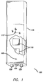
- FIG 1 shows a line drawing of an antenna system in accordance with the present invention.
- the antenna system of the present invention incorporates a camera (105) into the antenna radome (115) within which can be found the radiating structures of the antenna (110). Suitable cameras are commercially available. Also a variety of specific camera details are well known and accordingly such details are not described in detail.
- the camera may be configured within the radome and only the camera lens (105) is shown in the view of Figure 1 .
- the camera (115) is aligned to observe the landscape directly in front of the forward face of the antenna radome (115).
- Figure 1 shows the three dimensional reference axes (117) of the radome (115).
- radome reference axes (117) are given as X R , Y R , and Z R . Since the camera (105) is fixed to the radome, the pointing direction of the camera (115) is also fixed. The camera observation angle will generally be perpendicular to the X R / Z R plane but may have down tilt in the Y R / Z R plane.
- the radiation pattern boresight pointing direction of the radome internal antenna (110) could be different from the radome (115) attached camera. This pointing difference could be achieved by mechanically gimballing the antenna within the radome, by phase shifting the transmission angle of the individual radiating elements which make up the complete antenna, or by a combination of both means.
- patent application serial No. 12/074,980 filed March 7, 2008 patent application serial No. 12/074,473 filed March 4, 2008
- US Patent No. 5,949,303 describe beam pointing adjustment as well as beamwidth adjustment systems and methods which may be employed.
- Figure 1 shows three connectors on the bottom of the complete antenna system (100). Two of these connectors (120, 125) represent RF connectors.
- one physical structure may include dual antenna polarizations, as well as multiple band operation as well. Each polarization is used for diversity receive purposes. RF signals may be transmitted out of one or both polarizations. In wireless, the radiating patterns of both diversity polarizations are matched.
- the third connector (130) shown in Figure 1 is used for data communication purposes.
- the data communication could include such items as control of the antenna pointing direction, the antenna beamwidth, and operation & maintenance of any active electronics within the antenna structure. With the present invention, this data communication port would also provide control and data acquisition from the antenna camera (105). Those skilled in the art will appreciate that data communication could also take place via the RF connectors (120, 125) by frequency duplexing a data communication channel along with the RF signals. In this latter case, the data connector (130) could be omitted. Also the disclosures of the above noted patent applications and patent provide additional details on suitable control and RF communication links for bidirectional communication of image data from the camera to the remote user and antenna pointing and beamwidth control data to the antenna.
- the installer will generally mechanically attach the complete antenna (100) to a suitable antenna support structure. Attachments are generally performed on the back of the complete antenna structure (100). There may or may not be a means for the installer to point the exterior surface of the antenna radome (115) at the time of installation. For example on a typical communication tower, built for the purpose of antenna installation, such pointing is generally possible. When attaching to the side of a building, lease agreements with the building landlord may require a flush mounting. In either case the final pointing direction of the antenna radiating boresight can be difficult for the operator to determine after installation.
- FIG. 2 shows an example still image produced by the present invention.
- the image of Figure 2 includes an antenna pointing neutral position grid (210).
- the neutral position of the antenna represents the boresight pointing direction when pointing controls are set to zero.
- the neutral position is indicated by the central grid location (210).
- the image includes a reticle (215) showing the actual antenna radiating pattern pointing position.
- the bottom of the image provides data (220) including the reticle position as well as information regarding the current beamwidth of the antenna. This beamwidth information could be static or based on controlled adjustment depending on the antenna design.
- Figure 2 The information in Figure 2 would be used in several ways. First, a comparison of a current image with a past image would inform the user if the antenna has moved. Such movement would cause a shift in the image captured by the camera. Second, the image permits the user to make sure the boresight of the antenna is pointed at the desired target. For example, Figure 2 shows the antenna boresight pointed at a freeway just to the right of a lamppost. Such pointing could be aided using internet mapping software such as Google maps. Finally, the image permits the user to insure no new obstacles have obstructed the antenna coverage area.
- the advantage of image provided information is the volume of the content and the simple judgments that can be based on this content. Initial correct mounting can be determined by viewing the image during and just after installation. If the borders of the image change with time, the antenna is not properly secured. If the position of the reticle changes, a change has been commanded, either intentionally or unintentionally. This information can be easily determined regardless of season.
- the present invention could be used with antennas with or without pointing and beamwidth control.
- the above describes the advantages of using the invention on antennas with pointing and beamwidth controls.
- the invention would be helpful in instructing installation crews on proper mechanical alignment.
- images from such an antenna would also show if the antenna has moved with time. For example, severe weather may cause a mounted antenna to move.
- the present invention also provides an antenna position data acquisition and control method.
- FIG 3 the control flow of the antenna position data acquisition and control method is illustrated.
- an image taken from the antenna mounted camera is acquired along with position reference information which may include a neutral pointing position and an indicator, such as a reticle, corresponding to actual antenna radiating pattern pointing position (beam boresight).
- position reference information may include a neutral pointing position and an indicator, such as a reticle, corresponding to actual antenna radiating pattern pointing position (beam boresight).
- current beamwidth and beam pointing information is added to the image data. For example this may be text display data superimposed on the image.
- the camera image and superimposed beam information is transmitted to the remote user via one or more of the communication connections 120, 125 and 130 as described above.
- the received image with beam information is compared by the remote user to a desired beam position.
- the received image and position information can be compared to a prior image to see if the antenna or beam has moved unintentionally requiring correction.
- the image may be used to determine an adjustment to a new desired pointing position, as described above. Also any changes in the environment requiring beamwidth adjustment may be determined.
- control data to provide the desired correction in beam pointing direction and/or beamwidth is transmitted to the antenna and received at one or more of the communication connections 120, 125 and 130. This control data is used to actuate mechanical or beam phase control to provide the desired adjustment as described above and in the applications and patents mentioned above.
- the steps 305 and 320 may be dispensed with and as noted above the antenna position information may be used during installation to correct improper mounting by the on site installation crew or monitored remotely over time to detect movement due to weather or other causes to dispatch an installation repair crew. Also such installation monitoring may also be employed in an installation method for a system having beam pointing or beamwidth control as described above.
Landscapes
- Variable-Direction Aerials And Aerial Arrays (AREA)
Claims (9)
- Antennensystem, das zur Verwendung in einem drahtlosen Netzwerk und zur Fernpositionsüberwachung und -steuerung ausgebildet ist, aufweisend:eine Antenne;eine Kamera (105), die in einem unveränderlichen Verhältnis zur Antenne montiert ist, um somit eine Ansicht bereitzustellen, die im Allgemeinen in die Richtung der Hauptstrahlrichtung des Antennenstrahls verläuft; undeine Kommunikationsverbindung (130), die an die Kamera gekoppelt ist, um einer fernen Stelle Bilddaten von der Kamera (105) bereitzustellen, wobeidie Antenne mehrere ausstrahlende Elemente aufweist und wobei die Kommunikationsverbindung Bandbreitensteuersignale empfängt, die von der fernen Stelle bereitgestellt sind.
- Antennensystem nach Anspruch 1, wobei das Antennensystem ferner ein Radom (115) aufweist, das um die Antenne eingerichtet ist, und wobei die Kamera (105) am Radom (115) montiert ist; oder
die Kommunikationsverbindung von der fernen Stelle bereitgestellte Strahllagerichtungssteuersignale empfängt. - Verfahren zur Ferngewinnung von Antennenpositionierungsdaten, aufweisend:Gewinnen (300) eines Bildes einer Ansicht von einer Kamera, die in einem unveränderlichen Verhältnis zu einer Antenne montiert ist, im Allgemeinen in der Richtung der Hauptstrahlrichtung des Antennenstrahls; undBereitstellen (310) der Bilddaten an einer fernen Stelle;Hinzufügen (305) von Strahlbreiteninformationen zu den Bilddaten vor dem Bereitstellen der Bilddaten an der fernen Stelle; unddes Weiteren aufweisend ein Bereitstellen von Strahlbreiteneinstellungssteuerdaten an der Antennenstelle von der fernen Stelle.
- Verfahren zur Ferngewinnung von Antennenpositionierungsdaten nach Anspruch 3, wobei das Bild Positionsreferenzinformationen enthält.
- Verfahren zur Ferngewinnung von Antennenpositionierungsdaten nach Anspruch 4, wobei die Positionsreferenzinformationen einen Kameralagerichtungsreferenzmarker und einen Strahllagerichtungsreferenzmarker enthalten.
- Verfahren zur Ferngewinnung von Antennenpositionierungsdaten nach Anspruch 5, des Weiteren aufweisend ein Hinzufügen (305) von Strahllagepositionsdaten im Textformat zu den Bilddaten vor dem Bereitstellen der Bilddaten an der fernen Stelle.
- Verfahren zur Ferngewinnung von Antennenpositionierungsdaten nach Anspruch 3, des Weiteren aufweisend ein Verwenden der Bilddaten an der fernen Stelle zum Bestimmen der Antennenstrahllageposition relativ zu der gewünschten Lageposition.
- Verfahren zur Ferngewinnung von Antennenpositionierungsdaten nach Anspruch 7, wobei das Verfahren des Weiteren ein Bereitstellen (320) von Strahllageeinstellungssteuerdaten an der Antennenstelle von der fernen Stelle als Reaktion auf die Bestimmung von Antennenstrahllagepositionsinformationen aufweist;
oder
ein Verwenden der Bilddaten an der fernen Stelle zum Bestimmen der Antennenstrahllageposition relativ zu der gewünschten Lageposition ein Vergleichen (315) der empfangenen Bilddaten mit einem früheren Bild aufweist um festzustellen, ob die Antenne oder der Strahl eine unabsichtliche Bewegung erfahren hat, die eine Korrektur benötigt. - Verfahren zur Ferngewinnung von Antennenpositionierungsdaten nach Anspruch 5, wobei die Antenne in einem Radom eingerichtet ist und wobei die Kamera am Radom montiert ist.
Applications Claiming Priority (2)
| Application Number | Priority Date | Filing Date | Title |
|---|---|---|---|
| US93084207P | 2007-05-18 | 2007-05-18 | |
| PCT/US2008/006284 WO2008143971A1 (en) | 2007-05-18 | 2008-05-16 | System and method for remote antenna positioning data acquisition |
Publications (3)
| Publication Number | Publication Date |
|---|---|
| EP2158639A1 EP2158639A1 (de) | 2010-03-03 |
| EP2158639A4 EP2158639A4 (de) | 2014-11-26 |
| EP2158639B1 true EP2158639B1 (de) | 2016-06-29 |
Family
ID=40026979
Family Applications (1)
| Application Number | Title | Priority Date | Filing Date |
|---|---|---|---|
| EP08767748.0A Active EP2158639B1 (de) | 2007-05-18 | 2008-05-16 | System und verfahren zur entfernten erfassung von antennenpositionsdaten |
Country Status (3)
| Country | Link |
|---|---|
| US (1) | US7990325B2 (de) |
| EP (1) | EP2158639B1 (de) |
| WO (1) | WO2008143971A1 (de) |
Families Citing this family (19)
| Publication number | Priority date | Publication date | Assignee | Title |
|---|---|---|---|---|
| US20090141179A1 (en) * | 2007-11-27 | 2009-06-04 | Hyun Jung | Cellular Antenna Assembly With Video Capability |
| WO2010021418A1 (en) * | 2008-08-20 | 2010-02-25 | Kmw Inc. | Control system for antenna of mobile communication base station and image data offer system and method to use the control system |
| US8362969B2 (en) * | 2010-08-30 | 2013-01-29 | Arc Wireless Solutions, Inc. | Adjustable antenna baffling system |
| TWI433584B (zh) * | 2011-07-08 | 2014-04-01 | Accton Technology Corp | Outdoor wireless base station and its antenna adjustment method |
| US9281559B2 (en) * | 2011-11-29 | 2016-03-08 | Harris Corporation | Method for directed antenna alignment through augmented reality |
| JP5823019B2 (ja) * | 2012-03-13 | 2015-11-25 | 三菱電機株式会社 | アンテナ検査システム、アンテナ検査装置、アンテナ検査方法およびプログラム |
| US9690454B2 (en) * | 2013-03-15 | 2017-06-27 | Amir H. Rezvan | Methods and systems for remotely viewing and auditing cell sites comprising a digital data structure comprising a substantially 360 degree digital representation of the site |
| US20160056525A1 (en) | 2013-04-02 | 2016-02-25 | Telefonaktiebolaget L M Ericsson (Publ) | A Radio Antenna Alignment Tool |
| KR101900873B1 (ko) | 2014-05-27 | 2018-09-20 | 후아웨이 테크놀러지 컴퍼니 리미티드 | 안테나 엔지니어링 파라미터를 획득하는 방법, 장치 및 시스템 |
| US9811915B2 (en) * | 2015-08-24 | 2017-11-07 | Huawei Technologies Co., Ltd. | Integration of image/video pattern recognition in traffic engineering |
| WO2017063681A1 (en) * | 2015-10-13 | 2017-04-20 | Telefonaktiebolaget Lm Ericsson (Publ) | Method and tool for reflector alignment |
| US10340587B2 (en) | 2016-09-13 | 2019-07-02 | Laird Technologies, Inc. | Antenna assemblies having sealed cameras |
| US20210116490A1 (en) * | 2017-03-17 | 2021-04-22 | Nec Corporation | Antenna direction adjustment apparatus, antenna direction adjustment system, and method therefor |
| US10267888B2 (en) * | 2017-04-28 | 2019-04-23 | Higher Ground Llc | Pointing an antenna at a signal source using augmented reality |
| US10116893B1 (en) * | 2017-04-28 | 2018-10-30 | Higher Ground Llc | Selectively controlling a direction of signal transmission using adaptive augmented reality |
| US10374297B2 (en) | 2017-09-12 | 2019-08-06 | Laird Technologies, Inc. | Antenna assemblies having sealed cameras |
| WO2019195662A1 (en) * | 2018-04-05 | 2019-10-10 | Starry, Inc. | System and method for facilitating installation of user nodes in fixed wireless data network |
| WO2019200615A1 (en) * | 2018-04-20 | 2019-10-24 | Nokia Shanghai Bell Co., Ltd. | Apparatus, methods and computer programs for facilitating tuning of an antenna |
| US20220174221A1 (en) * | 2020-11-30 | 2022-06-02 | Multiwave Sensors Inc. | Camera in bracket and method to minimize blind spots to the transmission of antenna signals |
Family Cites Families (12)
| Publication number | Priority date | Publication date | Assignee | Title |
|---|---|---|---|---|
| SE504563C2 (sv) | 1995-05-24 | 1997-03-03 | Allgon Ab | Anordning för inställning av riktningen hos en antennlob |
| US5798983A (en) * | 1997-05-22 | 1998-08-25 | Kuhn; John Patrick | Acoustic sensor system for vehicle detection and multi-lane highway monitoring |
| US6400903B1 (en) * | 1999-12-23 | 2002-06-04 | Paul Conoval | Remote camera relay controller method and apparatus |
| JP2001267830A (ja) * | 2000-03-15 | 2001-09-28 | Hitachi Ltd | アンテナ駆動装置およびそれを用いた人工衛星追尾システム |
| US6611696B2 (en) * | 2001-05-02 | 2003-08-26 | Trex Enterprises Corporation | Method and apparatus for aligning the antennas of a millimeter wave communication link using a narrow band oscillator and a power detector |
| US7369160B2 (en) | 2001-06-15 | 2008-05-06 | Yokogawa Electric Corporation | Camera system for transferring both image data and an image processing program to transfer the image data to an external device |
| US6556916B2 (en) * | 2001-09-27 | 2003-04-29 | Wavetronix Llc | System and method for identification of traffic lane positions |
| US20040252197A1 (en) | 2003-05-05 | 2004-12-16 | News Iq Inc. | Mobile device management system |
| US20060017545A1 (en) | 2004-03-26 | 2006-01-26 | Volpi John P | Radio frequency identification interrogation systems and methods of operating the same |
| DE102005040414B4 (de) * | 2005-08-25 | 2007-07-26 | Wrobel, Achim, Dipl.-Ing. | Ausrichtung von Antennen |
| US7541943B2 (en) * | 2006-05-05 | 2009-06-02 | Eis Electronic Integrated Systems Inc. | Traffic sensor incorporating a video camera and method of operating same |
| WO2008109067A1 (en) | 2007-03-05 | 2008-09-12 | Powerwave Technologies, Inc. | Single pole vertically polarized variable azimuth beamwidth antenna for wireless network |
-
2008
- 2008-05-16 US US12/152,728 patent/US7990325B2/en active Active
- 2008-05-16 WO PCT/US2008/006284 patent/WO2008143971A1/en active Application Filing
- 2008-05-16 EP EP08767748.0A patent/EP2158639B1/de active Active
Also Published As
| Publication number | Publication date |
|---|---|
| WO2008143971A1 (en) | 2008-11-27 |
| EP2158639A1 (de) | 2010-03-03 |
| US20080284669A1 (en) | 2008-11-20 |
| EP2158639A4 (de) | 2014-11-26 |
| US7990325B2 (en) | 2011-08-02 |
Similar Documents
| Publication | Publication Date | Title |
|---|---|---|
| EP2158639B1 (de) | System und verfahren zur entfernten erfassung von antennenpositionsdaten | |
| US8299962B2 (en) | AISG inline tilt sensor system and method | |
| US11422219B2 (en) | Satellite antenna with sensor for line-of-sight detection | |
| US8184050B2 (en) | Antenna alignment and monitoring system and method using GNSS | |
| EP2013940B1 (de) | Zellularantenne, systeme und methoden dafür | |
| EP2580810B1 (de) | Bestimmung einer antennenausrichtung | |
| US8259020B1 (en) | Antenna system for satellite communication | |
| US8193983B1 (en) | Automated antenna alignment system | |
| US20160056525A1 (en) | A Radio Antenna Alignment Tool | |
| AU2010337831B2 (en) | System and method for accurately directing antennas | |
| US20200195340A1 (en) | Determining an attenuation environment of a satellite communication terminal | |
| US20180026718A1 (en) | Systems and methods for using drones for determining line-of-sight conditions in wireless networks | |
| CN106505318B (zh) | 一种双定向天线自适应对准通信方法 | |
| KR100924245B1 (ko) | 지향성 안테나의 방위각 및 고도 방향을 자동 결정하고 이를 캘리브레이션하는 시스템 및 방법 | |
| WO2017192714A1 (en) | System and method of adjusting antenna beam on antenna tower | |
| US8890757B1 (en) | Antenna system for satellite communication | |
| US7928895B2 (en) | Systems and methods for communication to a gimbal mounted device | |
| CN107819187B (zh) | 用于微波天线的对准装置、微波天线及对准方法 | |
| US10283860B2 (en) | Antenna device and antenna device control method | |
| US10620319B2 (en) | Device and method for generating and providing position information | |
| US20190148813A1 (en) | Imaging system and method for accurately directing antennas | |
| CA2980324C (en) | Elevation angle estimating device and method for user terminal placement | |
| JP2015065563A (ja) | 無線伝送システム | |
| WO2016032742A1 (en) | Use of geolocation information to optimize receiving antenna alignment | |
| CN116636084A (zh) | 移动通信基站天线的取向方向的管理方法和系统 |
Legal Events
| Date | Code | Title | Description |
|---|---|---|---|
| PUAI | Public reference made under article 153(3) epc to a published international application that has entered the european phase |
Free format text: ORIGINAL CODE: 0009012 |
|
| 17P | Request for examination filed |
Effective date: 20091214 |
|
| AK | Designated contracting states |
Kind code of ref document: A1 Designated state(s): AT BE BG CH CY CZ DE DK EE ES FI FR GB GR HR HU IE IS IT LI LT LU LV MC MT NL NO PL PT RO SE SI SK TR |
|
| AX | Request for extension of the european patent |
Extension state: AL BA MK RS |
|
| DAX | Request for extension of the european patent (deleted) | ||
| A4 | Supplementary search report drawn up and despatched |
Effective date: 20141023 |
|
| RIC1 | Information provided on ipc code assigned before grant |
Ipc: H01Q 1/22 20060101AFI20141017BHEP Ipc: H01Q 1/12 20060101ALN20141017BHEP Ipc: H01Q 3/00 20060101ALN20141017BHEP |
|
| RAP1 | Party data changed (applicant data changed or rights of an application transferred) |
Owner name: P-WAVE HOLDINGS, LLC |
|
| RAP1 | Party data changed (applicant data changed or rights of an application transferred) |
Owner name: POWERWAVE TECHNOLOGIES S.A.R.L. |
|
| RAP1 | Party data changed (applicant data changed or rights of an application transferred) |
Owner name: INTEL CORPORATION |
|
| REG | Reference to a national code |
Ref country code: DE Ref legal event code: R079 Ref document number: 602008044902 Country of ref document: DE Free format text: PREVIOUS MAIN CLASS: H01Q0003000000 Ipc: H01Q0001220000 |
|
| RIC1 | Information provided on ipc code assigned before grant |
Ipc: H01Q 3/00 20060101ALN20151201BHEP Ipc: H01Q 1/22 20060101AFI20151201BHEP Ipc: H01Q 1/12 20060101ALN20151201BHEP |
|
| GRAP | Despatch of communication of intention to grant a patent |
Free format text: ORIGINAL CODE: EPIDOSNIGR1 |
|
| INTG | Intention to grant announced |
Effective date: 20160108 |
|
| GRAS | Grant fee paid |
Free format text: ORIGINAL CODE: EPIDOSNIGR3 |
|
| GRAA | (expected) grant |
Free format text: ORIGINAL CODE: 0009210 |
|
| AK | Designated contracting states |
Kind code of ref document: B1 Designated state(s): AT BE BG CH CY CZ DE DK EE ES FI FR GB GR HR HU IE IS IT LI LT LU LV MC MT NL NO PL PT RO SE SI SK TR |
|
| REG | Reference to a national code |
Ref country code: GB Ref legal event code: FG4D |
|
| REG | Reference to a national code |
Ref country code: CH Ref legal event code: EP |
|
| REG | Reference to a national code |
Ref country code: AT Ref legal event code: REF Ref document number: 809745 Country of ref document: AT Kind code of ref document: T Effective date: 20160715 |
|
| REG | Reference to a national code |
Ref country code: IE Ref legal event code: FG4D |
|
| REG | Reference to a national code |
Ref country code: DE Ref legal event code: R096 Ref document number: 602008044902 Country of ref document: DE |
|
| REG | Reference to a national code |
Ref country code: LT Ref legal event code: MG4D |
|
| PG25 | Lapsed in a contracting state [announced via postgrant information from national office to epo] |
Ref country code: FI Free format text: LAPSE BECAUSE OF FAILURE TO SUBMIT A TRANSLATION OF THE DESCRIPTION OR TO PAY THE FEE WITHIN THE PRESCRIBED TIME-LIMIT Effective date: 20160629 Ref country code: LT Free format text: LAPSE BECAUSE OF FAILURE TO SUBMIT A TRANSLATION OF THE DESCRIPTION OR TO PAY THE FEE WITHIN THE PRESCRIBED TIME-LIMIT Effective date: 20160629 Ref country code: NO Free format text: LAPSE BECAUSE OF FAILURE TO SUBMIT A TRANSLATION OF THE DESCRIPTION OR TO PAY THE FEE WITHIN THE PRESCRIBED TIME-LIMIT Effective date: 20160929 |
|
| REG | Reference to a national code |
Ref country code: NL Ref legal event code: MP Effective date: 20160629 |
|
| PG25 | Lapsed in a contracting state [announced via postgrant information from national office to epo] |
Ref country code: HR Free format text: LAPSE BECAUSE OF FAILURE TO SUBMIT A TRANSLATION OF THE DESCRIPTION OR TO PAY THE FEE WITHIN THE PRESCRIBED TIME-LIMIT Effective date: 20160629 Ref country code: GR Free format text: LAPSE BECAUSE OF FAILURE TO SUBMIT A TRANSLATION OF THE DESCRIPTION OR TO PAY THE FEE WITHIN THE PRESCRIBED TIME-LIMIT Effective date: 20160930 Ref country code: LV Free format text: LAPSE BECAUSE OF FAILURE TO SUBMIT A TRANSLATION OF THE DESCRIPTION OR TO PAY THE FEE WITHIN THE PRESCRIBED TIME-LIMIT Effective date: 20160629 Ref country code: NL Free format text: LAPSE BECAUSE OF FAILURE TO SUBMIT A TRANSLATION OF THE DESCRIPTION OR TO PAY THE FEE WITHIN THE PRESCRIBED TIME-LIMIT Effective date: 20160629 Ref country code: SE Free format text: LAPSE BECAUSE OF FAILURE TO SUBMIT A TRANSLATION OF THE DESCRIPTION OR TO PAY THE FEE WITHIN THE PRESCRIBED TIME-LIMIT Effective date: 20160629 |
|
| REG | Reference to a national code |
Ref country code: AT Ref legal event code: MK05 Ref document number: 809745 Country of ref document: AT Kind code of ref document: T Effective date: 20160629 |
|
| PG25 | Lapsed in a contracting state [announced via postgrant information from national office to epo] |
Ref country code: CZ Free format text: LAPSE BECAUSE OF FAILURE TO SUBMIT A TRANSLATION OF THE DESCRIPTION OR TO PAY THE FEE WITHIN THE PRESCRIBED TIME-LIMIT Effective date: 20160629 Ref country code: EE Free format text: LAPSE BECAUSE OF FAILURE TO SUBMIT A TRANSLATION OF THE DESCRIPTION OR TO PAY THE FEE WITHIN THE PRESCRIBED TIME-LIMIT Effective date: 20160629 Ref country code: IS Free format text: LAPSE BECAUSE OF FAILURE TO SUBMIT A TRANSLATION OF THE DESCRIPTION OR TO PAY THE FEE WITHIN THE PRESCRIBED TIME-LIMIT Effective date: 20161029 Ref country code: IT Free format text: LAPSE BECAUSE OF FAILURE TO SUBMIT A TRANSLATION OF THE DESCRIPTION OR TO PAY THE FEE WITHIN THE PRESCRIBED TIME-LIMIT Effective date: 20160629 Ref country code: RO Free format text: LAPSE BECAUSE OF FAILURE TO SUBMIT A TRANSLATION OF THE DESCRIPTION OR TO PAY THE FEE WITHIN THE PRESCRIBED TIME-LIMIT Effective date: 20160629 Ref country code: SK Free format text: LAPSE BECAUSE OF FAILURE TO SUBMIT A TRANSLATION OF THE DESCRIPTION OR TO PAY THE FEE WITHIN THE PRESCRIBED TIME-LIMIT Effective date: 20160629 |
|
| PG25 | Lapsed in a contracting state [announced via postgrant information from national office to epo] |
Ref country code: ES Free format text: LAPSE BECAUSE OF FAILURE TO SUBMIT A TRANSLATION OF THE DESCRIPTION OR TO PAY THE FEE WITHIN THE PRESCRIBED TIME-LIMIT Effective date: 20160629 Ref country code: AT Free format text: LAPSE BECAUSE OF FAILURE TO SUBMIT A TRANSLATION OF THE DESCRIPTION OR TO PAY THE FEE WITHIN THE PRESCRIBED TIME-LIMIT Effective date: 20160629 Ref country code: PT Free format text: LAPSE BECAUSE OF FAILURE TO SUBMIT A TRANSLATION OF THE DESCRIPTION OR TO PAY THE FEE WITHIN THE PRESCRIBED TIME-LIMIT Effective date: 20161031 Ref country code: BE Free format text: LAPSE BECAUSE OF FAILURE TO SUBMIT A TRANSLATION OF THE DESCRIPTION OR TO PAY THE FEE WITHIN THE PRESCRIBED TIME-LIMIT Effective date: 20160629 Ref country code: PL Free format text: LAPSE BECAUSE OF FAILURE TO SUBMIT A TRANSLATION OF THE DESCRIPTION OR TO PAY THE FEE WITHIN THE PRESCRIBED TIME-LIMIT Effective date: 20160629 |
|
| REG | Reference to a national code |
Ref country code: DE Ref legal event code: R097 Ref document number: 602008044902 Country of ref document: DE |
|
| PLBE | No opposition filed within time limit |
Free format text: ORIGINAL CODE: 0009261 |
|
| STAA | Information on the status of an ep patent application or granted ep patent |
Free format text: STATUS: NO OPPOSITION FILED WITHIN TIME LIMIT |
|
| PG25 | Lapsed in a contracting state [announced via postgrant information from national office to epo] |
Ref country code: DK Free format text: LAPSE BECAUSE OF FAILURE TO SUBMIT A TRANSLATION OF THE DESCRIPTION OR TO PAY THE FEE WITHIN THE PRESCRIBED TIME-LIMIT Effective date: 20160629 |
|
| 26N | No opposition filed |
Effective date: 20170330 |
|
| STAA | Information on the status of an ep patent application or granted ep patent |
Free format text: STATUS: NO OPPOSITION FILED WITHIN TIME LIMIT |
|
| PG25 | Lapsed in a contracting state [announced via postgrant information from national office to epo] |
Ref country code: SI Free format text: LAPSE BECAUSE OF FAILURE TO SUBMIT A TRANSLATION OF THE DESCRIPTION OR TO PAY THE FEE WITHIN THE PRESCRIBED TIME-LIMIT Effective date: 20160629 Ref country code: LU Free format text: LAPSE BECAUSE OF NON-PAYMENT OF DUE FEES Effective date: 20170531 Ref country code: BG Free format text: LAPSE BECAUSE OF FAILURE TO SUBMIT A TRANSLATION OF THE DESCRIPTION OR TO PAY THE FEE WITHIN THE PRESCRIBED TIME-LIMIT Effective date: 20160929 |
|
| REG | Reference to a national code |
Ref country code: CH Ref legal event code: PL |
|
| GBPC | Gb: european patent ceased through non-payment of renewal fee |
Effective date: 20170516 |
|
| PG25 | Lapsed in a contracting state [announced via postgrant information from national office to epo] |
Ref country code: MC Free format text: LAPSE BECAUSE OF FAILURE TO SUBMIT A TRANSLATION OF THE DESCRIPTION OR TO PAY THE FEE WITHIN THE PRESCRIBED TIME-LIMIT Effective date: 20160629 |
|
| REG | Reference to a national code |
Ref country code: IE Ref legal event code: MM4A |
|
| PG25 | Lapsed in a contracting state [announced via postgrant information from national office to epo] |
Ref country code: LI Free format text: LAPSE BECAUSE OF NON-PAYMENT OF DUE FEES Effective date: 20170531 Ref country code: CH Free format text: LAPSE BECAUSE OF NON-PAYMENT OF DUE FEES Effective date: 20170531 |
|
| REG | Reference to a national code |
Ref country code: FR Ref legal event code: ST Effective date: 20180131 |
|
| PG25 | Lapsed in a contracting state [announced via postgrant information from national office to epo] |
Ref country code: LU Free format text: LAPSE BECAUSE OF NON-PAYMENT OF DUE FEES Effective date: 20170516 |
|
| PG25 | Lapsed in a contracting state [announced via postgrant information from national office to epo] |
Ref country code: GB Free format text: LAPSE BECAUSE OF NON-PAYMENT OF DUE FEES Effective date: 20170516 Ref country code: IE Free format text: LAPSE BECAUSE OF NON-PAYMENT OF DUE FEES Effective date: 20170516 |
|
| PG25 | Lapsed in a contracting state [announced via postgrant information from national office to epo] |
Ref country code: FR Free format text: LAPSE BECAUSE OF NON-PAYMENT OF DUE FEES Effective date: 20170531 |
|
| PG25 | Lapsed in a contracting state [announced via postgrant information from national office to epo] |
Ref country code: MT Free format text: LAPSE BECAUSE OF NON-PAYMENT OF DUE FEES Effective date: 20170516 |
|
| PG25 | Lapsed in a contracting state [announced via postgrant information from national office to epo] |
Ref country code: HU Free format text: LAPSE BECAUSE OF FAILURE TO SUBMIT A TRANSLATION OF THE DESCRIPTION OR TO PAY THE FEE WITHIN THE PRESCRIBED TIME-LIMIT; INVALID AB INITIO Effective date: 20080516 |
|
| PG25 | Lapsed in a contracting state [announced via postgrant information from national office to epo] |
Ref country code: CY Free format text: LAPSE BECAUSE OF NON-PAYMENT OF DUE FEES Effective date: 20160629 |
|
| PG25 | Lapsed in a contracting state [announced via postgrant information from national office to epo] |
Ref country code: TR Free format text: LAPSE BECAUSE OF FAILURE TO SUBMIT A TRANSLATION OF THE DESCRIPTION OR TO PAY THE FEE WITHIN THE PRESCRIBED TIME-LIMIT Effective date: 20160629 |
|
| P01 | Opt-out of the competence of the unified patent court (upc) registered |
Effective date: 20230518 |
|
| PGFP | Annual fee paid to national office [announced via postgrant information from national office to epo] |
Ref country code: DE Payment date: 20230418 Year of fee payment: 16 |