EP2158073B1 - Reifenabdichtvorrichtung - Google Patents
Reifenabdichtvorrichtung Download PDFInfo
- Publication number
- EP2158073B1 EP2158073B1 EP08749551.1A EP08749551A EP2158073B1 EP 2158073 B1 EP2158073 B1 EP 2158073B1 EP 08749551 A EP08749551 A EP 08749551A EP 2158073 B1 EP2158073 B1 EP 2158073B1
- Authority
- EP
- European Patent Office
- Prior art keywords
- sealant
- sealant container
- container
- removal
- port
- Prior art date
- Legal status (The legal status is an assumption and is not a legal conclusion. Google has not performed a legal analysis and makes no representation as to the accuracy of the status listed.)
- Active
Links
Images






Classifications
-
- B—PERFORMING OPERATIONS; TRANSPORTING
- B29—WORKING OF PLASTICS; WORKING OF SUBSTANCES IN A PLASTIC STATE IN GENERAL
- B29C—SHAPING OR JOINING OF PLASTICS; SHAPING OF MATERIAL IN A PLASTIC STATE, NOT OTHERWISE PROVIDED FOR; AFTER-TREATMENT OF THE SHAPED PRODUCTS, e.g. REPAIRING
- B29C73/00—Repairing of articles made from plastics or substances in a plastic state, e.g. of articles shaped or produced by using techniques covered by this subclass or subclass B29D
- B29C73/16—Auto-repairing or self-sealing arrangements or agents
- B29C73/166—Devices or methods for introducing sealing compositions into articles
-
- B—PERFORMING OPERATIONS; TRANSPORTING
- B29—WORKING OF PLASTICS; WORKING OF SUBSTANCES IN A PLASTIC STATE IN GENERAL
- B29L—INDEXING SCHEME ASSOCIATED WITH SUBCLASS B29C, RELATING TO PARTICULAR ARTICLES
- B29L2030/00—Pneumatic or solid tyres or parts thereof
Definitions
- the invention relates to a device for sealing inflatable articles, in particular a tire sealing device, comprising a sealing agent container containing a sealing means and a riser pipe which projects into the sealing agent container, a seal which seals the sealing agent container liquid-tight, and an inlet which opens into the sealing agent container , comprising a removal device for removing sealing means from the sealing agent container, which comprises a first connection for introducing compressed air and a second connection for discharging sealing means and is designed to be reversibly connected to the sealing agent container.
- Such a device which is held instead of a spare tire, for example in passenger cars to repair tire damage, for example, from DE 101 06 468 A1 known.
- the disadvantage of this is that the device described there either works with a non-sealed sealant container, which exposes the sealant to oxygen, or is closed with a sealing foil, which can only be destroyed by the application of a high air pressure.
- such pressure is difficult to achieve with conventional air pumps and represents an inconvenience to the user.
- a sealing device in which the sealing agent container is designed to be screwed onto the removal device.
- the removal device has a detachable closure arrangement for activation.
- the disadvantage of this is that the closure assembly can also be blasted off by pressure, which comes from the connected, still acted upon by residual pressure tires. In this case, it is possible that first sealing agent flows towards the compressor and makes it damaged or unusable.
- a device for sealing inflatable objects in which the sealing agent container must be provided separately with a compressed air connection and a connection for discharging the sealant.
- the US 2003/056851 discloses an apparatus for sealing an inflatable object, wherein a piston or nozzle displaceable by compressor pressure pierces a seal of a sealant container with a cutting projection.
- the device is suitable only for operation upside down.
- a similar designed device discloses the EP 1 621 325 A1 , but here is a filter or a sieve is moved with the cutting edge, that is to retain in the sealant as existing impurities. Again, the sealant bottle must be upside down for proper operation.
- the invention has for its object to overcome disadvantages in the prior art.
- the invention solves the problem by a generic device in which the removal device has a separator for breaking the seal.
- the device can be operated standing on the sealant through the presence of the riser in the sealant, which makes them very stable.
- the greatest weight of the device is namely caused by the sealing means, which is advantageously always near the bottom of the Abdichtschimiers and thus shifts the center of gravity of the entire device down. Bulky removal devices are thus unnecessary.
- a separating device for breaking through the seal is understood in particular to mean any component of the device for sealing inflatable articles which is designed to lift the integrity of the seal so that compressed air can flow into the sealing agent container and discharge sealing means.
- An easy-to-use device results when the removal device can be screwed onto the sealing agent container and the separation device is a cutting device which is designed to sever the seal of the sealing agent container when the removal device is screwed onto the sealing agent container. In this case, only the removal device must be screwed onto the sealing agent container by the user of the device in order to make the device ready for use.
- the invention relates to an embodiment in which the separating device comprises a movably mounted coupling stub, which is designed so that it, when the extraction device is connected to the Abdichtstoff employer and the first port is acted upon with compressed air, towards the sealant to moves, breaks through the seal and coupled with the riser sealing seal.
- the sealing agent container remains sealed until the first port is pressurized with compressed air. In pressurized state, there is no danger of sealant getting into the port provided for compressed air, thus becoming clogged or lost due to leakage and, before that, leakage of sealant through the seal is prevented.
- the coupling stub is formed on a coupling unit which is movably mounted between a rest position and a removal position in a housing of the removal device and having a connecting channel, wherein the coupling stub is coupled in the removal position with the riser sealing seal and the connecting channel only in the removal position connects the inlet of the sealant container with the second port.
- a particularly easy-to-use device results when the riser is arranged concentrically to a thread, by means of which the removal device can be screwed onto the sealant container.
- the inlet is then arranged annularly around the riser.
- the riser is supported by thin webs in the inlet.
- the device has a particularly low, even if correct Operation of the device in the sealant remaining residual amount when the riser extends beyond a geometric center of the Abdichtstoff organizations out into the Abdichtstoff practicer.
- the riser has a free end and rests with this on an inner wall of the Abdichtstoff practicers. Sealing means may then enter the riser through inlet openings provided at the free end, so that substantially all of the sealing means can leave the sealing agent container.
- the device comprises a compressed air source which is designed to be connectable exclusively to the first connection. This can be done, for example, by virtue of the compressed-air source having an output connection which can not be coupled to the second connection of the removal device. In this way, operator errors are avoided
- the device also comprises a valve unit for connection to a tire valve, in particular a tire valve, which is designed to be connectable exclusively to the second connection. This will prevent the valve unit from being mistakenly connected to the first port for the compressed air. In this way, incorrect operation is largely excluded.
- the sealing agent container has a stand surface facing away from the removal device or a support surface on which the removal device, ie the sealing agent container, can be set in a tilt-proof manner in the state connected to the removal device.
- the sealant can be tilted adjustable especially if it does not tip over on a tilted by 20 ° to the horizontal plane surface. This can be achieved, for example, in that the standing surface is designed such that a tilting point of the sealing agent container always lies beyond the vertical projection of the sealing agent container on the base surface.
- the tipping point is the location of the base of the sealant container. In other words, the points at which the sealant container contacts a flat, horizontal surface are from above In this way, a particularly secure standing sealant container is obtained.
- the riser is flexible and has at its free end a weight which is designed so that it always aligns the free end down.
- the device can also be operated lying.
- an embodiment is that the riser protrudes into the sealing agent container by such a small amount that substantially all of the sealing means can be removed from the sealing agent container when the device is operated downwards with the removal device.
- the sealant container in the "head-ÜberStellung" almost completely empty.
- a further embodiment consists in that the separating device is externally, in particular manually, operably formed and secured by a locking pin against unintentional actuation.
- FIG. 4 shows a view of another Reifenabdichtvorraum invention.
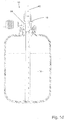
- FIG. 1 a shows a tire sealing device 10 comprising a sealing agent container 12 and a removal device 14.
- the sealant container 12 contains a predetermined amount of sealant 16, which is, for example, latex milk with added additives.
- sealant 16 is, for example, latex milk with added additives.
- the sealing agent container 12 projects beyond a geometric center M of the sealant 12 beyond a riser 18, which rests with a free end 20 on an inner wall 22 of the sealant 12.
- the riser 18 has at least one recess 24, can pass through the sealing means 16 into an interior of the riser 18.
- the riser 18 is mounted via an insert 26 in a container body 28 of the Abdichtstoff mattersers 12 concentric with the longitudinal axis L.
- an inlet 30 is formed, which surrounds the riser 18 in an annular shape and this holds over not shown in Figure la webs.
- the insert 26 may be in the form of a press fit into a threaded socket 32 which is an integral part of the container body 28 represents, fitted and has an open cross section, which allows easy filling with sealant 16.
- the insert 26 is permanently connected to the container body 28, for example glued or welded.
- the sealing container 12 is sealed by a seal 34 sealant and gas-tight. For this reason, the sealing means 16 is only subject to very little oxidative aging.
- the removal device 14 has a housing 36, on which a first connection 38 for introducing compressed air and a second connection 40 for discharging sealing means 16 are formed. On the housing 36, an internal thread 42 is also provided, which cooperates with an external thread 44 on the threaded connector 32.
- a separating device in the form of a cutting device 46 is provided, which is arranged radially on the outside of a coupling stub 48.
- the coupling stub 48 is in communication with the second port 40, but not with the first port 38 and has a pointed end 50 which is cylindrically shaped so that it can be coupled with the riser pipe 18 sealant tight.
- a sealing element preferably an O-ring 52nd
- the pointed end 50 first of all pierces the seal 34 and, on further rotation, the cutting device 46 subsequently cuts the seal 34 additionally.
- FIG. 1b shown situation in which the second port 40 is connected via the coupling stub 48 with the riser 18.
- the first connection 38 is connected via an annular channel 54 in the housing 36 and via the inlet 30 to the interior of the sealing agent container 12.
- a compressed air source not shown, such as a compressor, can then be connected via an adapter 58 (FIG. 1c).
- Figure 1d 11 shows the state in which compressed air 60 is conducted from the compressed air source into the sealing agent container 12, so that sealing means 16 through the riser 18, the coupling 48 and the second port 40, the Reifenabdichtvoratti 10th leaves and is introduced via a line not drawn in a damaged tire to close a hole there.
- FIG. 2a shows a second embodiment of a Reifenabdichtvorraum 10 according to the invention, in which the separating device is arranged in the form of the cutting device 46 on a movably mounted coupling unit 47, on which also the coupling stub 48 is formed.
- the coupling unit 47 is mounted in the housing 36 so that it has a rest position in FIG. 2a is shown, and a removal position, as in Figure 2d is shown can take.
- the coupling unit 47 is mounted in the housing 36 via two ring seals 62a, 62b. As a result, a cylinder volume 64 is formed that communicates with the first port 38, but not with the second port 40.
- the coupling unit 47 also has a connecting channel 66, which is formed in a connection stub 68.
- the connecting piece 68 is in the in Figure 2c shown rest position of a sealing sleeve 70 which is formed on the housing 36, surrounded that in the rest position from the first port 38 incoming compressed air can not get into the connecting piece 68.
- Figure 2c shows the state in which the first terminal 38 is connected to a not shown air source.
- the compressed air source may be, for example, a compressor or a compressed air cylinder. If the first port 38 is acted upon by compressed air, it passes into the cylinder volume 64 and exerts a pressure on the coupling unit 47, which then moves toward the sealing agent container 12. As a result, the pointed end 50 of the coupling stub 48 breaks through the seal 34 and the coupling stub 48 is connected to the riser pipe 18.
- the connecting piece 68 is moved so far out of the sealing sleeve 70 that compressed air can pass through the connecting channel 66 in the connecting piece 68 and through the inlet 30 into the sealing agent container 12.
- FIG. 2e pushes this compressed air sealing means 16 through the second port 40 out. From there, it is passed through a non-marked pressure hose to a likewise not marked tire.
- the compressed air is introduced through the second port 40 and the riser 18, so that the sealing means 16 is expelled through the first port 38.
- the cylinder volume 64 is connected exclusively to the second port 40.
- the free end 20 (see Figure la) of the riser 18 has a weight and the riser 18 is formed so that the weight aligns the free end 20 each down.
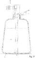
- the sealing agent container 12 shown in the figures also has a base S ( FIG. 2e ), with whom he is in contact on a level surface.
- the footprint S is formed so large that the ground can be inclined by 20 ° relative to the horizontal, for example, without the sealing device 10 tips over in a tilting point K.
- a particularly high stability is achieved if the standing surface S at the same time represents the largest cross-section with respect to a horizontal section through the sealing agent container 12 ( FIG. 2f ).
- FIG. 3 shows an alternative embodiment of a removal device 14, which surrounds a riser support 72 and on which a secured by a locking pin 74 cutting device is mounted in the form of a separating pin 76.
- the disconnect pin 76 can be hammered in by hand and sever the seal 34.
- the disconnect pin 76 is opposed via O-rings 78a, 78b, 78c the housing 36 sealed and hollow, so that it also acts as a second terminal 40.
- FIG. 4 shows a further alternative removal device 14, in which the riser support 72 is connected via a spring-loaded inlet valve 80 to the first port 38.
- the valve 80 is automatically opened by the connection operation of the air source to the extraction unit.
- the second port 40 has a spring-loaded exhaust valve 82 which opens as soon as the port is threaded onto the tire valve. Thus, both valves ensure a sealing of the sealant container.
- the pressure hose is attached, connecting the riser and exhaust valve.
- the second port 40 has a spring-loaded exhaust valve 82 on which is formed a port 84 for a hose of a tire to be repaired that holds the riser.
- All components of the tire sealing device are preferably made of plastic and, for example, injection-molded. It is also possible, for example, to produce the sealing agent container in a two-component injection molding process. It is also possible to connect the removal device 14 and the sealing agent container permanently, for example, to be welded. Another possibility is to provide the coupling unit 47 with a mandrel which penetrates into the Abêt ein in the Abdichtstoff employer and thus constitutes an anti-rotation.
Landscapes
- Engineering & Computer Science (AREA)
- Mechanical Engineering (AREA)
Description
- Die Erfindung betrifft eine Vorrichtung zum Abdichten aufblasbarer Gegenstände, insbesondere eine Reifenabdichtvorrichtung, mit einem Abdichtmittelbehälter, der ein Abdichtmittel enthält und ein Steigrohr, das in den Abdichtmittelbehälter ragt, ein Siegel, das den Abdichtmittelbehälter flüssigkeitsdicht verschließt, und einen Einlass, der in den Abdichtmittelbehälter mündet, umfasst, einer Entnahmevorrichtung zum Entnehmen von Abdichtmittel aus dem Abdichtmittelbehälter, die einen ersten Anschluss zum Einleiten von Druckluft und einen zweiten Anschluss zum Ableiten von Abdichtmittel umfasst und ausgebildet ist, um mit dem Abdichtmittelbehälter reversibel verbunden zu werden.
- Eine derartige Vorrichtung, die anstelle eines Reserverades beispielsweise in Pkw vorgehalten wird, um Reifenschäden zu reparieren, ist beispielsweise aus der
DE 101 06 468 A1 bekannt. Nachteilig daran ist, dass die dort beschriebene Vorrichtung entweder mit einem nicht versiegelten Abdichtmittelbehälter arbeitet, der das Abdichtmittel dem Sauerstoff aussetzt, oder aber mit einer Siegelfolie verschlossen ist, die nur durch das Aufbringen eines hohen Luftdrucks zerstört werden kann. Insbesondere dann, wenn die Vorrichtung für Fahrradreifen verwendet werden soll, ist mit herkömmlichen Luftpumpen ein derartiger Druck nur schwer zu erreichen und stellt eine Unbequemlichkeit für den Benutzer dar. - Aus der
EP 0 753 420 B1 ist eine Vorrichtung zum Abdichten von Reifen bei Pannen bekannt, bei der ein Druckmittel das Abdichtmittel aus einem gasdichten Abdichtmittelbehälter heraus treibt. Nachteilig hieran ist, dass nach Verwendung die komplette Vorrichtung entsorgt oder Dichtmittel unter hohem Aufwand in den Dichtmittelbehälter zugeführt werden muss. Beides ist für den Benutzer mit Aufwand verbunden. - Aus der
WO 01 72504 A1 - Auch aus der
DE 198 46 451 A1 ist eine Vorrichtung zum Abdichten aufblasbarer Gegenstände bekannt, die jedoch kein Steigrohr aufweist und damit nur betrieben werden kann, wenn die Entnahmevorrichtung eine hinreichend große Stellfläche aufweist. Dadurch wird die Entnahmevorrichtung nachteiligerweise sehr sperrig, was die Lagerung der Vorrichtung erschwert und materialintensiv ist. - Aus der
FR 671 659 - Die
US 2003/056851 offenbart eine Vorrichtung zum Abdichten eines aufblasbaren Objekts, bei dem ein durch Kompressordruck verschiebbarer Kolben oder Stutzen mit einem schneidenden Vorsprung ein Siegel eines Dichtmittelbehälters durchstößt. Die Vorrichtung ist jedoch nur für den Betrieb kopfüber geeignet. - Eine ähnliche ausgebildete Vorrichtung offenbart die
EP 1 621 325 A1 , hier wird jedoch mit dem schneidenden Vorsprung auch ein Filter bzw. ein Sieb verschoben, dass im Dichtmittel etwa vorhandene Verunreinigungen zurückhalten soll. Auch hier muss die Dichtmittelflasche zum einwandfreien Betrieb auf dem Kopf stehen. - Der Erfindung liegt die Aufgabe zugrunde, Nachteile im Stand der Technik zu überwinden. Die Erfindung löst das Problem durch eine gattungsgemäße Vorrichtung, bei der die Entnahmevorrichtung eine Trennvorrichtung zum Durchbrechen des Siegels besitzt.
- Vorteilhaft ist an der erfindungsgemäßen Vorrichtung, dass durch das Vorhandensein des Steigrohrs in dem Abdichtmittelbehälter die Vorrichtung auf dem Abdichtmittelbehälter stehend betrieben werden kann, was sie sehr kippstabil macht. Das größte Gewicht der Vorrichtung wird nämlich durch das Abdichtmittel verursacht, das sich vorteilhafterweise stets in Bodennähe des Abdichtmittelbehälters befindet und damit den Schwerpunkt der gesamten Vorrichtung nach unten verlagert. Sperrige Entnahmevorrichtungen werden damit entbehrlich.
- Es ist ein weiterer Vorteil der erfindungsgemäßen Vorrichtung, dass sie sehr einfach zu bedienen ist, was insbesondere deshalb von Vorteil ist, weil die Vorrichtung nur im selten auftretenden Fall einer Reifenpanne eingesetzt werden muss, so dass die Bedienung meist nicht geübt ist.
- Unter einer Trennvorrichtung zum Durchbrechen des Siegels wird im Rahmen der vorliegenden Beschreibung insbesondere jede Komponente der Vorrichtung zum Abdichten aufblasbarer Gegenstände verstanden, die dazu ausgebildet ist, um die Integrität des Siegels so weit aufzuheben, dass Druckluft in den Abdichtmittelbehälter einströmen und Abdichtmittel ausströmen kann.
- Eine einfach zu bedienende Vorrichtung ergibt sich, wenn die Entnahmevorrichtung auf den Abdichtmittelbehälter aufschraubbar ist und die Trennvorrichtung eine Schneidvorrichtung ist, die ausgebildet ist, um beim Aufschrauben der Entnahmevorrichtung auf den Abdichtmittelbehälter das Siegel des Abdichtmittelbehälters zu durchtrennen. In diesem Fall muss von dem Benutzer der Vorrichtung lediglich die Entnahmevorrichtung auf den Abdichtmittelbehälter geschraubt werden, um die Vorrichtung einsatzbereit zu machen.
- Die Erfindung betrifft eine Ausführungsform, bei der die die Trennvorrichtung einen beweglich gelagerten Koppelstutzen umfasst, der so ausgebildet ist, dass er sich dann, wenn die Entnahmevorrichtung mit dem Abdichtmittelbehälter verbunden ist und der erste Anschluss mit Druckluft beaufschlagt wird, in Richtung auf den Abdichtmittelbehälter zu bewegt, das Siegel durchbricht und mit dem Steigrohr abdichtmitteldicht koppelt. Hieran ist vorteilhaft, dass der Abdichtmittelbehälter so lange versiegelt bleibt, bis der erste Anschluss mit Druckluft beaufschlagt wird. In mit Druckluft beaufschlagtem Zustand besteht keine Gefahr, dass Abdichtmittel in den für Druckluft vorgesehenen Anschluss gelangt und diesen so verstopft oder durch Auslaufen verloren geht und davor wird ein Austreten von Abdichtmittel durch das Siegel verhindert.
- Es ist besonders bevorzugt, dass der Koppelstutzen an einer Koppeleinheit ausgebildet ist, die zwischen einer Ruhestellung und einer Entnahmestellung beweglich in einem Gehäuse der Entnahmevorrichtung gelagert ist und einen Verbindungskanal aufweist, wobei der Koppelstutzen in der Entnahmestellung mit dem Steigrohr abdichtmitteldicht gekoppelt ist und der Verbindungskanal nur in der Entnahmestellung den Einlass des Abdichtmittelbehälters mit dem zweiten Anschluss verbindet. Hierdurch wird sichergestellt, dass nach Aufschrauben der Entnahmevorrichtung auf den Abdichtmittelbehälter kein Abdichtmittel aus dem zweiten Anschluss auslaufen kann, so lange nicht der erste Anschluss mit Druckluft beaufschlagt ist. Ein weiterer Vorteil ist, dass ein fälschliches Anschließen einer Druckluftquelle an den zweiten Anschluss keine negativen Folgen hat. Wenn nämlich der zweite Anschluss irrtümlich mit Druckluft beaufschlagt wird, so liegt an dem ersten Anschluss keine Druckluft an und der Koppelstutzen gelangt nicht in die Entnahmestellung. Auf diese Weise werden Fehlbedienungen durch ungeübte Benutzer vermieden.
- Eine besonders einfach zu bedienende Vorrichtung ergibt sich, wenn das Steigrohr konzentrisch zu einem Gewinde angeordnet ist, mittels dem die Entnahmevorrichtung auf den Abdichtmittelbehälter aufschraubbar ist. Bevorzugt ist dann der Einlass ringförmig um das Steigrohr angeordnet. Beispielsweise wird das Steigrohr durch dünne Stege in dem Einlass gehaltert. Die Vorrichtung besitzt eine besonders geringe, auch bei korrekter Bedienung der Vorrichtung im Abdichtmittelbehälter verbleibende Restentnahmemenge, wenn das Steigrohr sich über einen geometrischen Mittelpunkt des Abdichtmittelbehälters hinaus in den Abdichtmittelbehälter erstreckt. Besonders bevorzugt besitzt das Steigrohr ein freies Ende und liegt mit diesem an einer Innenwand des Abdichtmittelbehälters an. Abdichtmittel kann dann durch am freien Ende vorgesehene Eintrittsöffnungen in das Steigrohr eintreten, so dass im Wesentlichen das gesamte Abdichtmittel den Abdichtmittelbehälter verlassen kann.
- In einer Ausführungsform umfasst die Vorrichtung eine Druckluftquelle, die ausschließlich mit dem ersten Anschluss verbindbar ausgebildet ist. Das kann beispielsweise dadurch geschehen, dass die Druckluftquelle einen Ausgangsanschluss besitzt, der mit dem zweiten Anschluss der Entnahmevorrichtung nicht koppelbar ist. Auf diese Weise werden Fehlbedienungen vermieden
- Die Vorrichtung umfasst zudem eine Ventileinheit zum Verbinden mit einem Reifenventil, insbesondere einem Autoreifenventil, die ausschließlich mit dem zweiten Anschluss verbindbar ausgebildet ist. Auf diese Weise wird verhindert, dass die Ventileinheit irrtümlich mit dem ersten Anschluss für die Druckluft verbunden wird. Auf diese Weise wird eine Fehlbedienung weitestgehend ausgeschlossen.
- Es ist bevorzugt, dass der Abdichtmittelbehälter eine der Entnahmevorrichtung abgewandte Standfläche bzw. eine Stellfläche aufweist, auf der die Entnahmevorrichtung, d.h. der Abdichtmittelbehälter im mit der Entnahmevorrichtung verbundenen Zustand kippsicher stellbar ist. Der Abdichtmittelbehälter ist insbesondere dann kippsicher stellbar, wenn er auf einem um 20° zur Horizontale geneigten ebenen Untergrund nicht umkippt. Das kann beispielsweise dadurch erreicht werden, dass die Standfläche so ausgebildet ist, dass ein Kipppunkt des Abdichtmittelbehälters stets jenseits der senkrechten Projektion des Abdichtmittelbehälters auf die Standfläche liegt. Der Kipppunkt ist die Stelle der Standfläche des Abdichtmittelbehälters. Mit anderen Worten stellen die Punkte, in denen der Abdichtmittelbehälter einen ebenen, horizontalen Untergrund berühren, die von oben gesehenen äußersten Punkte dar. Auf diese Weise wird ein besonders sicher stehender Abdichtmittelbehälter erhalten.
- In einer Ausführungsform ist das Steigrohr flexibel ausgebildet und besitzt an seinem freien Ende ein Gewicht, das so ausgebildet ist, dass es das freie Ende stets nach unten ausrichtet. In diesem Fall kann die Vorrichtung auch liegend betrieben werden. Alternativ ist es möglich, das Steigrohr so kurz auszubilden, dass es nur um einen so kleinen Betrag in den Abdichtmittelbehälter ragt, dass im Wesentlichen das gesamte Abdichtmittel aus dem Abdichtmittelbehälter entnehmbar ist, wenn die Vorrichtung mit der Entnahmevorrichtung nach unten betrieben wird.
- Eine Ausbildung besteht darin, dass das Steigrohr um einen so kleinen Betrag in den Abdichtmittelbehälter ragt, dass im Wesentlichen das gesamte Abdichtmittel aus dem Abdichtmittelbehälter entnehmbar ist, wenn die Vorrichtung mit der Entnahmevorrichtung nach unten betrieben wird. Damit lässt sich der Abdichtmittelbehälter in der "Kopf-ÜberStellung" nahezu vollständig entleeren.
- Eine weitere Ausbildung besteht darin, dass die Trennvorrichtung von außen, insbesondere manuell, betätigbar ausgebildet und durch einen Sicherungsstift gegen unbeabsichtigte Betätigung gesichert ist.
- Im Folgenden wird ein Ausführungsbeispiel der Erfindung anhand der beigefügten Figuren näher erläutert. Dabei zeigen die
- Figuren 1a, 1b, 1c und 1d
- eine erfindungsgemäße Reifenabdichtvorrichtung im Bedienungsablauf, die
- Figuren 2a, 2b, 2c, 2d,2e und 2f
- eine weitere Ausführungsform einer erfindungsgemäßen Reifenabdichtvorrichtung ebenfalls im Bedienungsablauf.
- Figur 3
- zeigt eine schematische Teilansicht einer weiteren Ausführungsform einer erfindungsgemäßen Reifenabdichtvorrichtung.
-
Figur 4 zeigt eine Ansicht einer weiteren erfindungsgemäßen Reifenabdichtvorrichtung. Figur la zeigt eine Reifenabdichtvorrichtung 10, die einen Abdichtmittelbehälter 12 und eine Entnahmevorrichtung 14 umfasst. Der Abdichtmittelbehälter 12 enthält eine vorgegebene Menge an Abdichtmittel 16, bei dem es sich beispielsweise um mit Zusätzen versehene Latexmilch handelt. In den Abdichtmittelbehälter 12 ragt über einen geometrischen Mittelpunkt M des Abdichtmittelbehälters 12 hinaus ein Steigrohr 18, das mit einem freien Ende 20 an einer Innenwand 22 des Abdichtmittelbehälters 12 anliegt. An seinem freien Ende 20 besitzt das Steigrohr 18 mindestens eine Ausnehmung 24, durch die Abdichtmittel 16 in ein Inneres des Steigrohrs 18 gelangen kann. - Das Steigrohr 18 ist über einen Einsatz 26 in einem Behälterkörper 28 des Abdichtmittelbehälters 12 konzentrisch zu dessen Längsachse L gelagert. Im Einsatz 26 ist ein Einlass 30 ausgebildet, der das Steigrohr 18 kreisringförmig umgibt und dieses über in Figur la nicht eingezeichnete Stege hält. Der Einsatz 26 kann in Form einer Presspassung in einen Gewindestutzen 32, der einen integralen Bestandteil des Behälterkörpers 28 darstellt, eingepasst sein und hat einen offenen Querschnitt, der ein leichtes Befüllen mit Abdichtmittel 16 erlaubt. Alternativ ist der Einsatz 26 mit dem Behälterkörper 28 dauerfest verbunden, beispielsweise verklebt oder verschweißt. Der Abdichtbehälter 12 ist über ein Siegel 34 abdichtmittel- und gasdicht verschlossen. Das Abdichtmittel 16 unterliegt aus diesem Grund nur einer sehr geringen oxidativen Alterung.
- Die Entnahmevorrichtung 14 besitzt ein Gehäuse 36, an dem ein erster Anschluss 38 zum Einleiten von Druckluft und ein zweiter Anschluss 40 zum Ableiten von Dichtmittel 16 ausgebildet sind. Am Gehäuse 36 ist zudem ein Innengewinde 42 vorgesehen, das mit einem Außengewinde 44 am Gewindestutzen 32 zusammenwirkt.
- Im Gehäuse 36 ist eine Trennvorrichtung in Form einer Schneidvorrichtung 46 vorgesehen, die radial außen an einem Koppelstutzen 48 angeordnet ist. Der Koppelstutzen 48 steht in Verbindung mit dem zweiten Anschluss 40, nicht aber mit dem ersten Anschluss 38 und besitzt ein spitzes Ende 50, das zylinderförmig so ausgebildet ist, dass es mit dem Steigrohr 18 abdichtmitteldicht koppelbar ist. In der Umgebung des spitzen Endes 50 besitzt der Koppelstutzen 48 dazu ein Dichtelement, vorzugsweise einen O-Ring 52.
- Wird die Entnahmevorrichtung 14 auf den Abdichtmittelbehälter 12 aufgeschraubt, so durchstößt zunächst das spitze Ende 50 das Siegel 34 und beim Weiterdrehen zerschneidet anschließend die Schneidvorrichtung 46 das Siegel 34 zusätzlich. Am Ende des Aufschraubens ergibt sich die in
Figur 1b gezeigte Situation, bei der der zweite Anschluss 40 über den Koppelstutzen 48 mit dem Steigrohr 18 verbunden ist. Gleichzeitig ist der erste Anschluss 38 über einen Ringkanal 54 im Gehäuse 36 und über den Einlass 30 mit dem Innenraum des Abdichtmittelbehälters 12 verbunden. Über ein Gewinde 56 kann anschließend eine nicht eingezeichnete Druckluftquelle, wie beispielsweise ein Kompressor, über einen Adapter 58 angeschlossen werden (Figur lc). -
Figur 1d zeigt den Zustand, in dem Druckluft 60 aus der Druckluftquelle in den Abdichtmittelbehälter 12 geleitet wird, so dass Abdichtmittel 16 durch das Steigrohr 18, den Koppelstutzen 48 und den zweiten Anschluss 40 die Reifenabdichtvorrichtung 10 verlässt und über eine nicht eingezeichnete Leitung in einen beschädigten Reifen eingeleitet wird, um dort ein Loch zu verschließen. -
Figur 2a zeigt eine zweite Ausführungsform einer erfindungsgemäßen Reifenabdichtvorrichtung 10, bei der die Trennvorrichtung in Form der Schneidvorrichtung 46 an einer beweglich gelagerten Koppeleinheit 47 angeordnet ist, an der auch der Koppelstutzen 48 ausgebildet ist. Die Koppeleinheit 47 ist im Gehäuse 36 so gelagert, dass sie eine Ruhestellung, die inFigur 2a gezeigt ist, und eine Entnahmestellung, wie sie inFigur 2d gezeigt ist, einnehmen kann. - In der Ruhestellung (
Figur 2a ) befindet sich der Koppelstutzen 48 in einer Position, in der auch ein Aufschrauben der Entnahmevorrichtung 14 auf den Abdichtmittelbehälter 12 nicht dazu führt, dass der Koppelstutzen 48 das Siegel 34 durchstößt. Dieser aufgeschraubte Zustand ist inFigur 2b gezeigt. - Wie
Figur 2c zeigt, ist die Koppeleinheit 47 über zwei Ringdichtungen 62a, 62b in dem Gehäuse 36 gelagert. Dadurch ist ein Zylindervolumen 64 gebildet, dass mit dem ersten Anschluss 38 in Verbindung steht, nicht aber mit dem zweiten Anschluss 40. Die Koppeleinheit 47 besitzt zudem einen Verbindungskanal 66, der in einem Verbindungsstutzen 68 ausgebildet ist. Der Verbindungsstutzen 68 wird in der inFigur 2c gezeigten Ruhestellung so von einer Dichthülse 70, die an dem Gehäuse 36 ausgebildet ist, umgeben, dass in der Ruhestellung aus dem ersten Anschluss 38 einströmende Druckluft nicht in den Verbindungsstutzen 68 gelangen kann. -
Figur 2c zeigt den Zustand, in dem der erste Anschluss 38 mit einer nicht eingezeichneten Luftquelle verbunden ist. Die Druckluftquelle kann beispielsweise ein Kompressor oder eine Druckluftflasche sein. Wird der erste Anschluss 38 mit Druckluft beaufschlagt, so gelangt diese in das Zylindervolumen 64 und übt einen Druck auf die Koppeleinheit 47 aus, die sich daraufhin auf den Abdichtmittelbehälter 12 zu bewegt. Dadurch durchbricht das spitze Ende 50 des Koppelstutzens 48 das Siegel 34 und der Koppelstutzen 48 wird mit dem Steigrohr 18 verbunden. - In dieser Stellung, die in
Figur 2d gezeigt ist, ist der Verbindungsstutzen 68 so weit aus der Dichthülse 70 heraus bewegt, dass Druckluft durch den Verbindungskanal 66 im Verbindungsstutzen 68 und durch den Einlass 30 in den Abdichtmittelbehälter 12 gelangen kann. Wie inFigur 2e gezeigt ist, drückt diese Druckluft Abdichtmittel 16 durch den zweiten Anschluss 40 heraus. Von dort aus wird es durch einen nicht eingezeichneten Druckschlauch zu einem ebenfalls nicht eingezeichneten Reifen geleitet. In einer alternativen Ausführungsform ist vorgesehen, dass die Druckluft durch den zweiten Anschluss 40 und das Steigrohr 18 eingeleitet wird, so dass das Abdichtmittel 16 durch den ersten Anschluss 38 ausgetrieben wird. Dazu ist das Zylindervolumen 64 ausschließlich mit dem zweiten Anschluss 40 verbunden. - Gemäß einer weiteren alternativen Ausführungsform besitzt das freie Ende 20 (vgl. Figur la) des Steigrohrs 18 ein Gewicht und das Steigrohr 18 ist so ausgebildet, dass das Gewicht das freie Ende 20 jeweils nach unten ausrichtet. Dadurch wird vorteilhafterweise erreicht, dass die Reifenabdichtvorrichtung nicht nur, wie in den Figuren la bis 1d und 2a bis 2f gezeigt, aufrecht stehend betrieben werden kann, sondern in jeder beliebigen Lage.
- Der in den Figuren gezeigte Abdichtmittelbehälter 12 weist zudem eine Standfläche S auf (
Figur 2e ), mit der er auf einem ebenen Untergrund in Kontakt steht. Die Standfläche S ist so groß ausgebildet, dass der Untergrund um beispielsweise 20° gegenüber der Horizontalen geneigt sein kann, ohne dass die Abdichtvorrichtung 10 in einem Kipppunkt K umkippt. Eine besonders große Standfestigkeit wird erreicht, wenn die Standfläche S gleichzeitig den größten Querschnitt bezüglich eines horizontalen Schnitts durch den Abdichtmittelbehälter 12 darstellt (Figur 2f ). -
Figur 3 zeigt eine alternative Ausführungsform einer Entnahmevorrichtung 14, die eine Steigrohrhalterung 72 umgibt und an der eine über einen Sicherungsstift 74 gesicherte Schneidvorrichtung in Form eines Trennbolzens 76 gelagert ist. Nach Entfernen des Trennsicherungsstifts 74 kann der Trennbolzen 76 per Hand eingeschlagen werden und durchtrennt das Siegel 34. Der Trennbolzen 76 ist über O-Ringe 78a, 78b, 78c gegenüber dem Gehäuse 36 abgedichtet und hohl ausgebildet, so dass er zugleich als zweiter Anschluss 40 fungiert. -
Figur 4 zeigt eine weitere alternative Entnahmevorrichtung 14, bei der die Steigrohrhalterung 72 über ein federbelastetes Einlassventil 80 mit dem ersten Anschluss 38 verbunden ist. Das Ventil 80 wird durch den Anschlussvorgang der Luftquelle an die Entnahmeeinheit automatisch geöffnet. Der zweite Anschluss 40 besitzt ein federbelastetes Auslassventil 82, welches sich öffnet, sobald der Anschluss auf das Reifenventil geschraubt wird. Somit sorgen beide Ventile für eine Abdichtung des Abdichtmittelbehälters. Am Anschluss 84 wird der Druckschlauch befestigt, der Steigrohr und Auslassventil verbindet. Der zweite Anschluss 40 besitzt ein federbelastetes Auslassventil 82, an dem ein Anschluss 84 für einen Schlauch eines zu reparierenden Reifens ausgebildet ist, die das Steigrohr halten. - Sämtliche Komponenten der Reifenabdichtvorrichtung sind bevorzugt aus Kunststoff gefertigt und beispielsweise spritzgegossen. Es ist zudem möglich, beispielsweise den Abdichtmittelbehälter in einem Zweikomponenten-Spritzgussverfahren herzustellen. Es ist zudem möglich, die Entnahmevorrichtung 14 und den Abdichtmittelbehälter dauerhaft zu verbinden, beispielsweise zu verschweißen. Eine weitere Möglichkeit ist, die Koppeleinheit 47 mit einem Dorn zu versehen, der in der Entnahmestellung in den Abdichtmittelbehälter eindringt und so eine Verdrehsicherung darstellt.
-
- 0
- Reifenabdichtvorrichtung
- 12
- Abdichtmittelbehälter
- 14
- Entnahmevorrichtung
- 16
- Abdichtmittel
- 18
- Steigrohr
- 20
- freies Ende
- 22
- Innenwand
- 24
- Ausnehmung
- 26
- Einsatz
- 28
- Behälterkörper
- 30
- Einlass
- 32
- Gewindestutzen
- 34
- Siegel
- 36
- Gehäuse
- 38
- erster Anschluss
- 40
- zweiter Anschluss
- 42
- Innengewinde
- 44
- Außengewinde
- 46
- Schneidvorrichtung
- 47
- Koppeleinheit
- 48
- Koppelstutzen
- 50
- spitzes Ende
- 52
- O-Ring
- 54
- Ringkanal
- 56
- Gewinde
- 58
- Adapter
- 60
- Druckluft
- 62a,b
- Ringdichtung
- 64
- Zylindervolumen
- 66
- Verbindungskanal
- 68
- Verbindungsstutzen
- 70
- Dichthülle
- 72
- Steigrohrhalterung
- 74
- Sicherungsstift
- 76
- Trennbolzen
- 78a,b,c
- O-Ring
- 80
- federbelastetes Einlassventil
- 82
- federbelastetes Auslassventil
- 84
- Anschluss
- M
- Mittelpunkt
- L
- Längsachse
- S
- Standfläche
- K
- Kipppunkt
Claims (6)
- Vorrichtung zum Abdichten aufblasbarer Gegenstände, insbesondere Reifenabdichtvorrichtung, mit(a) einem Abdichtmittelbehälter (12), der- ein Abdichtmittel (16) enthält und- ein Steigrohr (18), das in den Abdichtmittelbehälter (12) ragt,- ein Siegel (34), das in den Abdichtmittelbehälter (12) abdichtmitteldicht verschließt, und- einen Einlass (30), der in den Abdichtmittelbehälter (12) mündet, umfasst,(b) einer Entnahmevorrichtung (14) zum Entnehmen von Abdichtmittel (16) aus dem Abdichtmittelbehälter (12), diewobei die Entnahmevorrichtung (14) auf den aufrecht stehend betriebenen Abdichtmittelbehälter (12) aufschraubbar ist und die Trennvorrichtung eine Schneidvorrichtung (46) ist, wobei der Abdichtmittelbehälter (12) eine Standfläche aufweist, mit der er auf einem Untergrund in Kontakt steht,- einen ersten Anschluss (38) zum Einleiten von Druckluft und- einen zweiten Anschluss (40) zum Ableiten von Abdichtmittel (16) umfasst und- ausgebildet ist, um mit dem Abdichtmittelbehälter (12) reversibel verbunden zu werden, sowie- eine Trennvorrichtung (46) zum Durchbrechen des Siegels (34) besitzt,
dadurch gekennzeichnet, dass die Trennvorrichtung (46) einen beweglich gelagerten Koppelstutzen (48) umfasst, der so ausgebildet ist, dass er sich nur dann, wenn die Entnahmevorrichtung (14) mit dem Abdichtmittelbehälter (12) verbunden ist und der erste Anschluss (38) mit Druckluft beaufschlagt wird, in Richtung auf den Abdichtmittelbehälter (12) zu bewegt, das Siegel (34) durchbricht und mit dem Steigrohr (18) abdichtmitteldicht koppelt. - Vorrichtung nach Anspruch 1, dadurch gekennzeichnet, dass der Koppelstutzen (48) an einer Koppeleinheit (47) ausgebildet ist, die zwischen einer Ruhestellung und einer Entnahmestellung beweglich in einem Gehäuse (36) der Entnahmevorrichtung (14) gelagert ist und einen Verbindungskanal (66) aufweist, wobei der Koppelstutzen (48) in der Entnahmestellung mit dem Steigrohr (18) abdichtmitteldicht gekoppelt ist und der Verbindungskanal (66) nur in der Entnahmestellung den Einlass (30) mit dem zweiten Anschluss (40) verbindet.
- Vorrichtung nach einem der vorstehenden Ansprüche, dadurch gekennzeichnet, dass das Steigrohr (18) konzentrisch zu einem Gewinde (42) angeordnet ist, mittels dem die Entnahmevorrichtung (14) auf den Abdichtmittelbehälter (12) aufschraubbar ist.
- Vorrichtung nach Anspruch 6, dadurch gekennzeichnet, dass das Steigrohr (18) ein freies Ende (20) besitzt und mit dem freien Ende (20) an einer Innenwand (22) des Abdichtmittelbehälters (12) anliegt.
- Vorrichtung nach einem der vorstehenden Ansprüche, dadurch gekennzeichnet, dass der Abdichtmittelbehälter (12) eine der Entnahmevorrichtung (14) abgewandte Standfläche (S) aufweist, die so ausgebildet ist, dass der Abdichtmittelbehälter (12) im mit der Entnahmevorrichtung (14) verbundenen Zustand kippsicher stellbar ist.
- Vorrichtung nach Anspruch 5, dadurch gekennzeichnet, dass die Standfläche (S) so ausgebildet ist, dass ein Kipppunkt (K) des Abdichtmittelbehälters(12) stets jenseits der senkrechten Projektion des Abdichtmittelbehälters (12) auf die Standfläche (S) liegt
Applications Claiming Priority (2)
| Application Number | Priority Date | Filing Date | Title |
|---|---|---|---|
| DE102007026776A DE102007026776A1 (de) | 2007-06-09 | 2007-06-09 | Reifenabdichtvorrichtung |
| PCT/EP2008/054472 WO2008151870A2 (de) | 2007-06-09 | 2008-04-14 | Reifenabdichtvorrichtung |
Publications (2)
| Publication Number | Publication Date |
|---|---|
| EP2158073A2 EP2158073A2 (de) | 2010-03-03 |
| EP2158073B1 true EP2158073B1 (de) | 2019-03-06 |
Family
ID=39708821
Family Applications (1)
| Application Number | Title | Priority Date | Filing Date |
|---|---|---|---|
| EP08749551.1A Active EP2158073B1 (de) | 2007-06-09 | 2008-04-14 | Reifenabdichtvorrichtung |
Country Status (4)
| Country | Link |
|---|---|
| EP (1) | EP2158073B1 (de) |
| CN (1) | CN101730619B (de) |
| DE (1) | DE102007026776A1 (de) |
| WO (1) | WO2008151870A2 (de) |
Families Citing this family (9)
| Publication number | Priority date | Publication date | Assignee | Title |
|---|---|---|---|---|
| CN102275315A (zh) * | 2010-06-12 | 2011-12-14 | 大捷达实业(深圳)有限公司 | 轮胎补胎液罐 |
| BR112013007705A2 (pt) | 2010-10-18 | 2016-08-09 | Kraton Polymers Us Llc | solução tendo uma composição de copolímero em bloco sulfonado, película ou membrana, dispersão aquosa, compósito, composição de copolímeto em bloco sulfonado, processo, método para formar uma composição de copolímero em bloco sulfonado, e, célula eletrodialítica |
| JP5364136B2 (ja) * | 2011-09-20 | 2013-12-11 | 住友ゴム工業株式会社 | パンク修理キット |
| DE102013101110A1 (de) * | 2013-02-05 | 2014-08-07 | Continental Reifen Deutschland Gmbh | Asymmetrischer Hubkolbenverdichter |
| WO2015022630A1 (en) * | 2013-08-12 | 2015-02-19 | Tek Global S.R.L. | Disposable sealant liquid canister for an inflatable article repair and relative production method |
| ITTO20130900A1 (it) * | 2013-11-05 | 2015-05-06 | Tek Global Srl | Contenitore di liquido sigillante usa e getta per un kit di riparazione e gonfiaggio di articoli gonfiabili e relativo metodo di realizzazione |
| US9873557B2 (en) | 2013-08-12 | 2018-01-23 | Tek Global S.R.L. | Disposable canister for sealant for inflatable article repair and inflation kit, and production thereof |
| JP2017071128A (ja) | 2015-10-07 | 2017-04-13 | 横浜ゴム株式会社 | パンク修理液収容容器 |
| US11498295B2 (en) | 2018-07-17 | 2022-11-15 | Aircom Automotive Sp. z o.o. Sp. k. | Device for sealing pneumatic tires |
Citations (7)
| Publication number | Priority date | Publication date | Assignee | Title |
|---|---|---|---|---|
| DE10106468A1 (de) * | 2001-02-13 | 2002-08-14 | Michael Stehle | Vorrichtung zum Ausbringen von Reifendichtmittel |
| US20020121331A1 (en) * | 1995-07-11 | 2002-09-05 | Sumitomo Rubber Industries, Ltd. | Preparation for sealing punctured tires and apparatus for the sealing and pumping up of tires |
| DE20212101U1 (de) * | 2002-08-06 | 2003-01-16 | Continental Aktiengesellschaft, 30165 Hannover | Vorrichtung zum Abdichten aufblasbarer Gegenstände |
| US20030056851A1 (en) * | 2001-02-16 | 2003-03-27 | Eriksen Steen Mandsfelt | Device for sealing and inflating an inflatable object |
| DE202005005291U1 (de) * | 2005-04-04 | 2005-09-08 | Wang, Min-Hsieng | Reifenflickmasse-Spender |
| EP1621325A1 (de) * | 2004-07-29 | 2006-02-01 | Continental Aktiengesellschaft | Vorrichtung zum Abdichten von Reifen |
| DE202006001994U1 (de) * | 2006-02-07 | 2007-06-06 | Stehle, Michael | Vorrichtung zum Ausbringen von Reifendichtmittel aus einem Behälter |
Family Cites Families (5)
| Publication number | Priority date | Publication date | Assignee | Title |
|---|---|---|---|---|
| FR671659A (fr) | 1929-03-18 | 1929-12-16 | Dispositif pour l'injection, dans les chambres à air de pneumatiques, de produits obturateurs | |
| DE19846451C5 (de) * | 1998-10-08 | 2018-08-23 | Sumitomo Rubber Industries Ltd. | Vorrichtung zum Abdichten aufblasbarer Gegenstände, insbesondere Reifen |
| DE10015166A1 (de) | 2000-03-27 | 2001-10-04 | Dunlop Gmbh | Abdichtvorrichtung |
| JP4133945B2 (ja) * | 2004-06-28 | 2008-08-13 | 住友ゴム工業株式会社 | タイヤのパンクシーリング剤送給、抜取り装置 |
| CA2622768C (en) * | 2005-09-13 | 2014-01-21 | Trydel Research Pty. Ltd. | Improvements in sealing apparatus |
-
2007
- 2007-06-09 DE DE102007026776A patent/DE102007026776A1/de not_active Withdrawn
-
2008
- 2008-04-14 EP EP08749551.1A patent/EP2158073B1/de active Active
- 2008-04-14 CN CN200880019443.8A patent/CN101730619B/zh active Active
- 2008-04-14 WO PCT/EP2008/054472 patent/WO2008151870A2/de not_active Ceased
Patent Citations (7)
| Publication number | Priority date | Publication date | Assignee | Title |
|---|---|---|---|---|
| US20020121331A1 (en) * | 1995-07-11 | 2002-09-05 | Sumitomo Rubber Industries, Ltd. | Preparation for sealing punctured tires and apparatus for the sealing and pumping up of tires |
| DE10106468A1 (de) * | 2001-02-13 | 2002-08-14 | Michael Stehle | Vorrichtung zum Ausbringen von Reifendichtmittel |
| US20030056851A1 (en) * | 2001-02-16 | 2003-03-27 | Eriksen Steen Mandsfelt | Device for sealing and inflating an inflatable object |
| DE20212101U1 (de) * | 2002-08-06 | 2003-01-16 | Continental Aktiengesellschaft, 30165 Hannover | Vorrichtung zum Abdichten aufblasbarer Gegenstände |
| EP1621325A1 (de) * | 2004-07-29 | 2006-02-01 | Continental Aktiengesellschaft | Vorrichtung zum Abdichten von Reifen |
| DE202005005291U1 (de) * | 2005-04-04 | 2005-09-08 | Wang, Min-Hsieng | Reifenflickmasse-Spender |
| DE202006001994U1 (de) * | 2006-02-07 | 2007-06-06 | Stehle, Michael | Vorrichtung zum Ausbringen von Reifendichtmittel aus einem Behälter |
Also Published As
| Publication number | Publication date |
|---|---|
| DE102007026776A1 (de) | 2008-12-11 |
| WO2008151870A2 (de) | 2008-12-18 |
| CN101730619B (zh) | 2014-08-13 |
| EP2158073A2 (de) | 2010-03-03 |
| WO2008151870A3 (de) | 2009-02-12 |
| CN101730619A (zh) | 2010-06-09 |
Similar Documents
| Publication | Publication Date | Title |
|---|---|---|
| EP1121324B1 (de) | Abdichtvorrichtung | |
| EP2158073A2 (de) | Reifenabdichtvorrichtung | |
| EP1299227B1 (de) | Abdichtvorrichtung | |
| DE102010010361B4 (de) | Vorrichtung zum Einbringen von Luft und/oder Abdichtmittel in einen Reifen | |
| DE102009060272B4 (de) | Vorrichtung zum Einbringen von Luft und/oder Abdichtmittel in einen Reifen | |
| EP4061624B1 (de) | Vorrichtung zum transportieren von druckluft und/oder dichtmittel in einen fahrzeugluftreifen und tragbares/transportables system zum abdichten und aufpumpen von fahrzeugluftreifen | |
| DE69102842T2 (de) | Vorrichtung zum Imprägnieren von Flüssigkeiten mit Gas. | |
| DE10245318A1 (de) | Formverfahren, insbesondere Blas- und/oder Vakuumformverfahren, zum Herstellen eines mit einem abzugebenden Medium gefüllten Abgabebehälters | |
| EP0240969B1 (de) | Reifenfüllgerät, insbesondere zum Füllen von Fahrradreifen | |
| EP2807018B1 (de) | Rückflusssicherung | |
| DE102015119917A1 (de) | Verfahren und Vorrichtung zum Ausbringen eines Mittels zum Abdichten eines aufblasbaren Gegenstandes | |
| DE10110713C2 (de) | Handpumpe mit automatischer und Handaufpumpfunktion | |
| EP2276624B1 (de) | Pannenhilfesystem | |
| EP1642704A2 (de) | Abdichtvorrichtung | |
| EP3294462A1 (de) | Sicherheits- und regelvorrichtung für druckbehälter und druckbehälter mit einer solchen sicherheits- und regelvorrichtung | |
| DE3346850A1 (de) | Verbindungsvorrichtung, insbesondere fuer endoskope | |
| DE102007003667B4 (de) | Vorrichtung zum Abdichten und Aufpumpen aufblasbarer Gegenstände | |
| DE2018964B2 (de) | Tragbares absaugegeraet fuer medizinische zwecke | |
| DE112015001840B4 (de) | Behälter für Reparaturflüssigkeit für platte Reifen und Verfahren zum Einspritzen von Reparaturflüssigkeit | |
| EP1893423A2 (de) | Einrichtung zum zuführen von dichtungsflüssigkeit in einen luftreifen | |
| DE3912623A1 (de) | Gasflaschenventil | |
| DE202007009152U1 (de) | Vorrichtung zum Abdichten von Reifen | |
| DE102005021073B4 (de) | Vorrichtung zum Abdichten und Aufpumpen aufblasbarer Gegenstände | |
| DE29825074U1 (de) | Abdichtvorrichtung | |
| DE102007030462A1 (de) | Vorrichtung zum Abdichten von Reifen |
Legal Events
| Date | Code | Title | Description |
|---|---|---|---|
| PUAI | Public reference made under article 153(3) epc to a published international application that has entered the european phase |
Free format text: ORIGINAL CODE: 0009012 |
|
| 17P | Request for examination filed |
Effective date: 20100111 |
|
| AK | Designated contracting states |
Kind code of ref document: A2 Designated state(s): AT BE BG CH CY CZ DE DK EE ES FI FR GB GR HR HU IE IS IT LI LT LU LV MC MT NL NO PL PT RO SE SI SK TR |
|
| AX | Request for extension of the european patent |
Extension state: AL BA MK RS |
|
| DAX | Request for extension of the european patent (deleted) | ||
| 17Q | First examination report despatched |
Effective date: 20130415 |
|
| STAA | Information on the status of an ep patent application or granted ep patent |
Free format text: STATUS: EXAMINATION IS IN PROGRESS |
|
| GRAP | Despatch of communication of intention to grant a patent |
Free format text: ORIGINAL CODE: EPIDOSNIGR1 |
|
| STAA | Information on the status of an ep patent application or granted ep patent |
Free format text: STATUS: GRANT OF PATENT IS INTENDED |
|
| INTG | Intention to grant announced |
Effective date: 20181203 |
|
| GRAS | Grant fee paid |
Free format text: ORIGINAL CODE: EPIDOSNIGR3 |
|
| GRAA | (expected) grant |
Free format text: ORIGINAL CODE: 0009210 |
|
| STAA | Information on the status of an ep patent application or granted ep patent |
Free format text: STATUS: THE PATENT HAS BEEN GRANTED |
|
| AK | Designated contracting states |
Kind code of ref document: B1 Designated state(s): AT BE BG CH CY CZ DE DK EE ES FI FR GB GR HR HU IE IS IT LI LT LU LV MC MT NL NO PL PT RO SE SI SK TR |
|
| REG | Reference to a national code |
Ref country code: GB Ref legal event code: FG4D Free format text: NOT ENGLISH |
|
| REG | Reference to a national code |
Ref country code: CH Ref legal event code: EP Ref country code: AT Ref legal event code: REF Ref document number: 1103970 Country of ref document: AT Kind code of ref document: T Effective date: 20190315 |
|
| REG | Reference to a national code |
Ref country code: DE Ref legal event code: R096 Ref document number: 502008016633 Country of ref document: DE |
|
| REG | Reference to a national code |
Ref country code: IE Ref legal event code: FG4D Free format text: LANGUAGE OF EP DOCUMENT: GERMAN |
|
| REG | Reference to a national code |
Ref country code: NL Ref legal event code: MP Effective date: 20190306 |
|
| REG | Reference to a national code |
Ref country code: LT Ref legal event code: MG4D |
|
| PG25 | Lapsed in a contracting state [announced via postgrant information from national office to epo] |
Ref country code: FI Free format text: LAPSE BECAUSE OF FAILURE TO SUBMIT A TRANSLATION OF THE DESCRIPTION OR TO PAY THE FEE WITHIN THE PRESCRIBED TIME-LIMIT Effective date: 20190306 Ref country code: SE Free format text: LAPSE BECAUSE OF FAILURE TO SUBMIT A TRANSLATION OF THE DESCRIPTION OR TO PAY THE FEE WITHIN THE PRESCRIBED TIME-LIMIT Effective date: 20190306 Ref country code: NO Free format text: LAPSE BECAUSE OF FAILURE TO SUBMIT A TRANSLATION OF THE DESCRIPTION OR TO PAY THE FEE WITHIN THE PRESCRIBED TIME-LIMIT Effective date: 20190606 Ref country code: LT Free format text: LAPSE BECAUSE OF FAILURE TO SUBMIT A TRANSLATION OF THE DESCRIPTION OR TO PAY THE FEE WITHIN THE PRESCRIBED TIME-LIMIT Effective date: 20190306 |
|
| PG25 | Lapsed in a contracting state [announced via postgrant information from national office to epo] |
Ref country code: LV Free format text: LAPSE BECAUSE OF FAILURE TO SUBMIT A TRANSLATION OF THE DESCRIPTION OR TO PAY THE FEE WITHIN THE PRESCRIBED TIME-LIMIT Effective date: 20190306 Ref country code: NL Free format text: LAPSE BECAUSE OF FAILURE TO SUBMIT A TRANSLATION OF THE DESCRIPTION OR TO PAY THE FEE WITHIN THE PRESCRIBED TIME-LIMIT Effective date: 20190306 Ref country code: GR Free format text: LAPSE BECAUSE OF FAILURE TO SUBMIT A TRANSLATION OF THE DESCRIPTION OR TO PAY THE FEE WITHIN THE PRESCRIBED TIME-LIMIT Effective date: 20190607 Ref country code: HR Free format text: LAPSE BECAUSE OF FAILURE TO SUBMIT A TRANSLATION OF THE DESCRIPTION OR TO PAY THE FEE WITHIN THE PRESCRIBED TIME-LIMIT Effective date: 20190306 Ref country code: BG Free format text: LAPSE BECAUSE OF FAILURE TO SUBMIT A TRANSLATION OF THE DESCRIPTION OR TO PAY THE FEE WITHIN THE PRESCRIBED TIME-LIMIT Effective date: 20190606 |
|
| PG25 | Lapsed in a contracting state [announced via postgrant information from national office to epo] |
Ref country code: EE Free format text: LAPSE BECAUSE OF FAILURE TO SUBMIT A TRANSLATION OF THE DESCRIPTION OR TO PAY THE FEE WITHIN THE PRESCRIBED TIME-LIMIT Effective date: 20190306 Ref country code: ES Free format text: LAPSE BECAUSE OF FAILURE TO SUBMIT A TRANSLATION OF THE DESCRIPTION OR TO PAY THE FEE WITHIN THE PRESCRIBED TIME-LIMIT Effective date: 20190306 Ref country code: CZ Free format text: LAPSE BECAUSE OF FAILURE TO SUBMIT A TRANSLATION OF THE DESCRIPTION OR TO PAY THE FEE WITHIN THE PRESCRIBED TIME-LIMIT Effective date: 20190306 Ref country code: RO Free format text: LAPSE BECAUSE OF FAILURE TO SUBMIT A TRANSLATION OF THE DESCRIPTION OR TO PAY THE FEE WITHIN THE PRESCRIBED TIME-LIMIT Effective date: 20190306 Ref country code: IT Free format text: LAPSE BECAUSE OF FAILURE TO SUBMIT A TRANSLATION OF THE DESCRIPTION OR TO PAY THE FEE WITHIN THE PRESCRIBED TIME-LIMIT Effective date: 20190306 Ref country code: SK Free format text: LAPSE BECAUSE OF FAILURE TO SUBMIT A TRANSLATION OF THE DESCRIPTION OR TO PAY THE FEE WITHIN THE PRESCRIBED TIME-LIMIT Effective date: 20190306 Ref country code: PT Free format text: LAPSE BECAUSE OF FAILURE TO SUBMIT A TRANSLATION OF THE DESCRIPTION OR TO PAY THE FEE WITHIN THE PRESCRIBED TIME-LIMIT Effective date: 20190706 |
|
| PG25 | Lapsed in a contracting state [announced via postgrant information from national office to epo] |
Ref country code: PL Free format text: LAPSE BECAUSE OF FAILURE TO SUBMIT A TRANSLATION OF THE DESCRIPTION OR TO PAY THE FEE WITHIN THE PRESCRIBED TIME-LIMIT Effective date: 20190306 |
|
| REG | Reference to a national code |
Ref country code: CH Ref legal event code: PL |
|
| REG | Reference to a national code |
Ref country code: DE Ref legal event code: R097 Ref document number: 502008016633 Country of ref document: DE |
|
| REG | Reference to a national code |
Ref country code: BE Ref legal event code: MM Effective date: 20190430 |
|
| PG25 | Lapsed in a contracting state [announced via postgrant information from national office to epo] |
Ref country code: IS Free format text: LAPSE BECAUSE OF FAILURE TO SUBMIT A TRANSLATION OF THE DESCRIPTION OR TO PAY THE FEE WITHIN THE PRESCRIBED TIME-LIMIT Effective date: 20190706 Ref country code: LU Free format text: LAPSE BECAUSE OF NON-PAYMENT OF DUE FEES Effective date: 20190414 |
|
| PLBE | No opposition filed within time limit |
Free format text: ORIGINAL CODE: 0009261 |
|
| STAA | Information on the status of an ep patent application or granted ep patent |
Free format text: STATUS: NO OPPOSITION FILED WITHIN TIME LIMIT |
|
| PG25 | Lapsed in a contracting state [announced via postgrant information from national office to epo] |
Ref country code: LI Free format text: LAPSE BECAUSE OF NON-PAYMENT OF DUE FEES Effective date: 20190430 Ref country code: CH Free format text: LAPSE BECAUSE OF NON-PAYMENT OF DUE FEES Effective date: 20190430 Ref country code: MC Free format text: LAPSE BECAUSE OF FAILURE TO SUBMIT A TRANSLATION OF THE DESCRIPTION OR TO PAY THE FEE WITHIN THE PRESCRIBED TIME-LIMIT Effective date: 20190306 Ref country code: DK Free format text: LAPSE BECAUSE OF FAILURE TO SUBMIT A TRANSLATION OF THE DESCRIPTION OR TO PAY THE FEE WITHIN THE PRESCRIBED TIME-LIMIT Effective date: 20190306 |
|
| 26N | No opposition filed |
Effective date: 20191209 |
|
| PG25 | Lapsed in a contracting state [announced via postgrant information from national office to epo] |
Ref country code: BE Free format text: LAPSE BECAUSE OF NON-PAYMENT OF DUE FEES Effective date: 20190430 Ref country code: SI Free format text: LAPSE BECAUSE OF FAILURE TO SUBMIT A TRANSLATION OF THE DESCRIPTION OR TO PAY THE FEE WITHIN THE PRESCRIBED TIME-LIMIT Effective date: 20190306 |
|
| PG25 | Lapsed in a contracting state [announced via postgrant information from national office to epo] |
Ref country code: TR Free format text: LAPSE BECAUSE OF FAILURE TO SUBMIT A TRANSLATION OF THE DESCRIPTION OR TO PAY THE FEE WITHIN THE PRESCRIBED TIME-LIMIT Effective date: 20190306 |
|
| PG25 | Lapsed in a contracting state [announced via postgrant information from national office to epo] |
Ref country code: IE Free format text: LAPSE BECAUSE OF NON-PAYMENT OF DUE FEES Effective date: 20190414 |
|
| REG | Reference to a national code |
Ref country code: AT Ref legal event code: MM01 Ref document number: 1103970 Country of ref document: AT Kind code of ref document: T Effective date: 20190414 |
|
| PG25 | Lapsed in a contracting state [announced via postgrant information from national office to epo] |
Ref country code: AT Free format text: LAPSE BECAUSE OF NON-PAYMENT OF DUE FEES Effective date: 20190414 |
|
| PG25 | Lapsed in a contracting state [announced via postgrant information from national office to epo] |
Ref country code: CY Free format text: LAPSE BECAUSE OF FAILURE TO SUBMIT A TRANSLATION OF THE DESCRIPTION OR TO PAY THE FEE WITHIN THE PRESCRIBED TIME-LIMIT Effective date: 20190306 |
|
| PG25 | Lapsed in a contracting state [announced via postgrant information from national office to epo] |
Ref country code: HU Free format text: LAPSE BECAUSE OF FAILURE TO SUBMIT A TRANSLATION OF THE DESCRIPTION OR TO PAY THE FEE WITHIN THE PRESCRIBED TIME-LIMIT; INVALID AB INITIO Effective date: 20080414 Ref country code: MT Free format text: LAPSE BECAUSE OF FAILURE TO SUBMIT A TRANSLATION OF THE DESCRIPTION OR TO PAY THE FEE WITHIN THE PRESCRIBED TIME-LIMIT Effective date: 20190306 |
|
| REG | Reference to a national code |
Ref country code: DE Ref legal event code: R081 Ref document number: 502008016633 Country of ref document: DE Owner name: CONTINENTAL REIFEN DEUTSCHLAND GMBH, DE Free format text: FORMER OWNER: CONTINENTAL REIFEN DEUTSCHLAND GMBH, 30165 HANNOVER, DE |
|
| PGFP | Annual fee paid to national office [announced via postgrant information from national office to epo] |
Ref country code: FR Payment date: 20240426 Year of fee payment: 17 |
|
| PGFP | Annual fee paid to national office [announced via postgrant information from national office to epo] |
Ref country code: DE Payment date: 20250430 Year of fee payment: 18 |
|
| PGFP | Annual fee paid to national office [announced via postgrant information from national office to epo] |
Ref country code: GB Payment date: 20250423 Year of fee payment: 18 |
|
| PG25 | Lapsed in a contracting state [announced via postgrant information from national office to epo] |
Ref country code: FR Free format text: LAPSE BECAUSE OF NON-PAYMENT OF DUE FEES Effective date: 20250430 |