EP2157948B1 - Wound treatment device employing negative pressure - Google Patents
Wound treatment device employing negative pressure Download PDFInfo
- Publication number
- EP2157948B1 EP2157948B1 EP08756312.8A EP08756312A EP2157948B1 EP 2157948 B1 EP2157948 B1 EP 2157948B1 EP 08756312 A EP08756312 A EP 08756312A EP 2157948 B1 EP2157948 B1 EP 2157948B1
- Authority
- EP
- European Patent Office
- Prior art keywords
- chamber
- structures
- wound
- embossed structures
- negative pressure
- Prior art date
- Legal status (The legal status is an assumption and is not a legal conclusion. Google has not performed a legal analysis and makes no representation as to the accuracy of the status listed.)
- Active
Links
Images

Classifications
-
- A—HUMAN NECESSITIES
- A61—MEDICAL OR VETERINARY SCIENCE; HYGIENE
- A61F—FILTERS IMPLANTABLE INTO BLOOD VESSELS; PROSTHESES; DEVICES PROVIDING PATENCY TO, OR PREVENTING COLLAPSING OF, TUBULAR STRUCTURES OF THE BODY, e.g. STENTS; ORTHOPAEDIC, NURSING OR CONTRACEPTIVE DEVICES; FOMENTATION; TREATMENT OR PROTECTION OF EYES OR EARS; BANDAGES, DRESSINGS OR ABSORBENT PADS; FIRST-AID KITS
- A61F13/00—Bandages or dressings; Absorbent pads
- A61F13/05—Bandages or dressings; Absorbent pads specially adapted for use with sub-pressure or over-pressure therapy, wound drainage or wound irrigation, e.g. for use with negative-pressure wound therapy [NPWT]
-
- A—HUMAN NECESSITIES
- A61—MEDICAL OR VETERINARY SCIENCE; HYGIENE
- A61M—DEVICES FOR INTRODUCING MEDIA INTO, OR ONTO, THE BODY; DEVICES FOR TRANSDUCING BODY MEDIA OR FOR TAKING MEDIA FROM THE BODY; DEVICES FOR PRODUCING OR ENDING SLEEP OR STUPOR
- A61M1/00—Suction or pumping devices for medical purposes; Devices for carrying-off, for treatment of, or for carrying-over, body-liquids; Drainage systems
- A61M1/64—Containers with integrated suction means
- A61M1/68—Containers incorporating a flexible member creating suction
- A61M1/684—Containers incorporating a flexible member creating suction bellows-type
-
- A—HUMAN NECESSITIES
- A61—MEDICAL OR VETERINARY SCIENCE; HYGIENE
- A61M—DEVICES FOR INTRODUCING MEDIA INTO, OR ONTO, THE BODY; DEVICES FOR TRANSDUCING BODY MEDIA OR FOR TAKING MEDIA FROM THE BODY; DEVICES FOR PRODUCING OR ENDING SLEEP OR STUPOR
- A61M1/00—Suction or pumping devices for medical purposes; Devices for carrying-off, for treatment of, or for carrying-over, body-liquids; Drainage systems
- A61M1/80—Suction pumps
- A61M1/82—Membrane pumps, e.g. bulbs
-
- A—HUMAN NECESSITIES
- A61—MEDICAL OR VETERINARY SCIENCE; HYGIENE
- A61M—DEVICES FOR INTRODUCING MEDIA INTO, OR ONTO, THE BODY; DEVICES FOR TRANSDUCING BODY MEDIA OR FOR TAKING MEDIA FROM THE BODY; DEVICES FOR PRODUCING OR ENDING SLEEP OR STUPOR
- A61M1/00—Suction or pumping devices for medical purposes; Devices for carrying-off, for treatment of, or for carrying-over, body-liquids; Drainage systems
- A61M1/90—Negative pressure wound therapy devices, i.e. devices for applying suction to a wound to promote healing, e.g. including a vacuum dressing
- A61M1/91—Suction aspects of the dressing
- A61M1/915—Constructional details of the pressure distribution manifold
-
- A—HUMAN NECESSITIES
- A61—MEDICAL OR VETERINARY SCIENCE; HYGIENE
- A61M—DEVICES FOR INTRODUCING MEDIA INTO, OR ONTO, THE BODY; DEVICES FOR TRANSDUCING BODY MEDIA OR FOR TAKING MEDIA FROM THE BODY; DEVICES FOR PRODUCING OR ENDING SLEEP OR STUPOR
- A61M1/00—Suction or pumping devices for medical purposes; Devices for carrying-off, for treatment of, or for carrying-over, body-liquids; Drainage systems
- A61M1/71—Suction drainage systems
- A61M1/73—Suction drainage systems comprising sensors or indicators for physical values
Definitions
- the invention relates generally to the field of wound treatment, and more particularly, to a device for treating wounds with negative pressure and/or therapeutic modalities.
- Many wounds can be treated by the application of negative pressure.
- the method of such treatment has been practiced for many years.
- the benefits of such treatment can include: reduction of edema; reduction of wound exudate; reduction of wound size; and stimulation of formation of granulation tissue.
- Existing devices and appliances for the provision of negative pressure wound therapy are complex.
- Such devices typically encompass a porous insert such as foam or gauze that is placed into the wound; a tube connecting the insert to a source of suction; a flexible cover draped over these components and sealed to the skin around the wound; an electrically powered suction pump; controls to operate the pump and monitor the system; containers to collect wound fluids; filters to process the materials removed from the wound; and safety systems to prevent harm to the patient and to block the escape of biological materials into the outside environment.
- These devices are expensive, labor intensive, and restrictive of patient mobility.
- the many components, particularly the seals around the insert and the tube tend to leak. Therefore, suction must be applied either continuously or frequently.
- Continuous suction is typically achieved by a vacuum pump powered by an electric motor.
- These systems require complex means to measure, monitor, and control the operation of the pump in order to ensure the safety of the patient.
- many negative pressure devices are contraindicated in the presence of necrotic tissue, invasive infection, active bleeding, and exposed blood vessels. They require the use of a porous insert (i.e., a sponge, foam, gauze, mesh, etc.) in the wound.
- the insert may present two problems: growth of tissue into the insert, and the harboring of infectious and/or undesirable materials in the insert. Wound tissue can grow into and around such inserts, causing adverse results to the healing process. Moreover, such inserts can retain wound fluid and microorganisms, and can therefore become contaminated and/or infected, presenting an adverse effect to the healing process.
- the high cost of these devices may deter or delay their use on patients.
- WO 2007/002835 A2 discloses a wound dressing.
- the plurality of structures and the chamber are part of a single ply of material.
- each of the structures in the plurality of structures is semi-rigid.
- the device includes a wedge-shaped manual pump, and the treatment space is in fluid communication with the wedge-shaped manual pump.
- the wedge-shaped manual pump may include a spring that biases the wedge-shaped manual pump to an uncompressed position.
- chamber wall or “wall” mean any part of the chamber device that forms or encloses the chamber treatment space.
- view means a view from the inside of the chamber treatment space looking toward the interior surface of the chamber wall.
- the present invention is directed to providing a simple, safe, disposable, and cost-effective device that is easy to install and operate, that allows freedom of motion to the patient, and that overcomes, or at least reduces the effects of, one or more of the problems set forth above.
- the present invention does not require the use of a porous insert.
- the one-piece construction of the device eliminates virtually all leaks, therefore preserving and maintaining negative pressure within the wound without the need for constant or frequent regeneration of negative pressure.
- the structure of the device is configured to promote wound healing and to create pathways through which negative pressure can be distributed and maintained in the treatment space.
- the indications for the present invention may be expanded beyond the limitations imposed on current devices.
- the cost-effectiveness of the present invention may lead to the provision of negative pressure wound therapy on a more widespread basis and earlier in the timeline of wound care.
- a wound treatment device including a chamber defining a treatment space around the wound.
- the flexible adhesive base of the chamber forms a water-tight and gas-tight seal.
- a tube communicates from the treatment space to a source of suction.
- the suction source also serves as a receptacle for materials removed from the chamber. All components preferably are inexpensive, lightweight, and disposable.
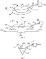
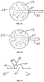
- the device 20 includes a chamber 22 defining a treatment space 24 and a base 26 that may be sealed to a skin surface 28 of a patient over a wound 30.
- the chamber 22 has a bellows configuration with a fold 23.
- the invention is not so limited, and other configurations of a chamber formed of a flexible, moisture and gas impermeable material may be used. Materials from which the device 20 may be made will be discussed in further detail below.
- the device 20 can be designed for use with any wound or body part, using circular, square, rectangular, tubular, pouch, envelope or other shapes.
- a chamber in the form of a tube or sleeve for placement over a limb is shown in Fig. 19 .
- a dermal or cutaneous adhesive material may be provided on a bottom surface of the base 26 for providing a fluid-tight seal with sufficient adhesive strength to prevent inadvertent removal of the chamber 22 or breach of the fluid-tight seal during normal patient movement. Numerous adhesive materials sufficient for these purposes are known to those of ordinary skill in the art.
- a tube 32 is attached to the chamber 22 preferably at a location spaced above the base 26 and communicates with the treatment space 24.
- the tube 32 is constructed to maintain its shape without collapsing and to permit the passage of wound fluids and wound debris.
- the tube 32 may be permanently fixed to the chamber 22, or a fitting 25 may be provided to allow the attachment and removal of the tube 32 or any other device that can deliver material or therapies to, or remove material from, the treatment space 24.
- the tube 32 may terminate at a wall of the chamber 22, or it may extend through the wall a distance and terminate within the treatment space 24, where it may communicate with such space, with channels formed on the inner surface of the chamber wall, or with folds formed in the chamber wall.
- the tube 32 may connect to the chamber 22 with a Luer fitting.
- the tube 32 is sealed to the chamber 22 in such a manner as to prevent the escape of liquid or gas from the treatment space 24 to the outside environment.
- a distal end of the tube 32 terminates at a suction device 34.
- the suction device 34 may be a pump, although other types of devices may be used as discussed below.
- a fitting 33 may be provided to permit the detachment and reattachment of a suction device 34 to the tube 32.
- a sectional view of the device 20 is provided, showing a second tube 35 attached to the chamber 22 and communicating with the treatment space 24, with channels, or with folds.
- a distal end of the tube 35 terminates in a portal 36.
- the invention is not limited to any number of communicating tubes, and multiple tubes and portals may be provided for accessing the treatment space 24.
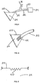
- Fig. 4 shows the device in Fig. 1 with a branch of the tube 32 that leads to a portal 36.
- the portal 36 may be used for the delivery of therapeutic modalities -- such as antimicrobials, antibiotics, antifungals, and analgesics -- prior to, during, or after the delivery of negative pressure.
- the portal 36 may be a Luer fitting configured for attachment to a container or a syringe.
- therapeutic modalities may be delivered through the same tube 32 that communicates with the suction device 34.
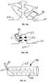
- Fig. 5 the end of the tube 32 extending into the chamber space 24 is shown with multiple apertures 44.
- the purpose of the apertures 44 is to ensure that gases, liquids, wound fluid, debris, and other materials can flow and move out of the chamber space 24 into the tube 32 without impediment.
- the interior surfaces of the chamber wall may be configured with structures 40 that are engineered on the surfaces.
- the portions of the interior surfaces with engineered structures 40 may be varied from that shown in the figures, and preferably a high percentage of the interior surfaces include engineered structures 40.
- the structures preferably cover at least 50% of the interior surfaces, and more preferably at least 95% of the interior surfaces. These structures are raised when viewed from within the chamber space 24, and they intrude into such space in directions generally perpendicular to the interior surfaces of the chamber space 24.
- These structures can be any shape, including without limitation a cone, a pyramid, a pentagon, a hexagon, a half sphere, a dome, a rod, an elongated ridge with rounded sides, or an elongated ridge with square sides.
- the structures can be provided as identical shapes, or in any combination of shapes.
- the structures can be provided with identical sizes, or in any combination of different sizes.
- the structures may be uniformly or non-uniformly spaced from each other.
- the structures may be separated by a portion of the surface of the chamber 22.
- the distance of intrusion into the chamber treatment space 24 from the chamber wall by such structures is preferably between .01mm and 20mm, and is more preferably between 1mm and 1 cm.
- the spacing between such structures is preferably between .01mm and 5cm.
- the engineered structures 40 interface with the wound surface during use of the device 20.
- One purpose of these structures is to ensure that negative pressure established within the chamber space 24 is evenly distributed and maintained throughout such space. As negative pressure is established within the tube that leads to the source of suction, the chamber will lie tighter against the wound tissue.
- the device 20 includes the engineered surfaces 40 in order to define pathways to establish, distribute, and maintain negative pressure across the wound surface and prevent complete contact between the inner surfaces of the chamber and the wound tissue. Without such structures, the chamber wall would make complete contact with the wound surface. As a result, there would be no space within which negative pressure could be established, distributed, and maintained. Therefore, the engineered structures are preferably semi-rigid.
- the term "semi-rigid" should be understood as meaning that deformation only occurs at a microscopic level under operating negative pressures in the range of 3,400-13,800 Pa (0.5-2 psi).
- the engineered structures may be somewhat flexible depending on the spacing between the structures.
- the structures are engineered to reduce the extent to which wound tissue can enter the space between the structures, so that a sufficient amount of open space is maintained.
- the flexible chamber is movable over a range of positions.
- the range of positions includes a first position, such as the position shown in Figs. 1 and 2 , in which the engineered structures 40 are spaced apart from the opening of the chamber defined by the base 26.
- the range of positions also includes a second position in which at least some of the engineered structures 40 are positioned in the opening of the chamber. The second position is preferably a position in which the engineered structures 40 engage the wound.
- the chamber wall can be formed of any appropriate medical grade material that has the following characteristics: flexibility, conformability, gas impermeability, liquid impermeability, the ability to be formed, tooled, and engineered, and the ability to retain the shape, function, and effectiveness of raised engineered structures under desired ranges of negative pressure.
- the material is preferably hypo-allergenic and provided to a medical facility in a sterile condition.
- the chamber device may be made of a flexible, conformable material such as polyurethane, although other similar materials may also be used.
- the chamber is preferably designed to provide sufficient material to lie against the surface of the wound tissue without special sizing, trimming, or other customizing operations.
- the chamber may be made from a single ply of material, or may be constructed of multiple layers of material in and on which the structures are engineered. It should be understood that a single ply chamber may be made of multiple sheets of material during manufacturing, but is provided to a medical facility in a state in which the multiple sheets are bonded or otherwise connected to one another. For example, individual three dimensional shapes may be adhered or bonded to the inner surface of the chamber wall during manufacturing to provide the engineered structures.
- a single ply chamber could also be formed from a single sheet of material that defines both the chamber walls and the engineered structures.
- a multiple layer chamber is provided to a medical facility in a state in which layers of material are stacked to form the chamber.
- the layer facing the interior treatment space of the chamber could be a layer containing engineered structures that is bonded onto a generally flat layer of material (or multiple sheets of generally flat layers) by a medical practitioner.
- Engineered structures can be made by techniques familiar to those in the art, such as embossing, stamping, molding, forming, or bonding. According to the present invention, the structures are created by embossing their shape into the material. The embossed structures are left in a concave state relative to the outside of the chamber as shown in Fig. 6 . Embossed structures may also be formed on a single ply of material that also forms the walls of the chamber and the base. This may provide a chamber that is relatively flexible and semi-rigid structures on a single ply of material. According to an example useful for an understanding of the invention, the cavities may be filled with a suitable material to render the structures solid. As another example useful for understanding of the invention, solid structures can be affixed to the inner surfaces of the chamber.
- Fig. 6 is a side sectional view of a portion of a chamber wall, showing engineered structures 40 on the interior surface of the material that faces treatment space 24. Structures 40 are identical in shape and size, and are positioned uniformly apart from one another.
- Fig. 7 is a side sectional view showing engineered structures 41 and 42 intruding into the chamber space, where structures 41 intrude farther than structures 42, and the structures are configured in a regular alternating pattern of 41-42-41-42 and so forth.
- Fig. 6 is
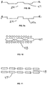
- FIG. 8 is a side sectional view showing engineered structures 43, 44, and 45 intruding into the chamber space, where structures 43 intrude farther than structures 44 and 45, structures 44 intrude less than structures 43 but farther than structures 45, and structures 45 intrude less than structures 43 and 44. These structures are configured in a regular alternating pattern of 43-45-44-45-43-45-44-45-43 and so forth.
- the embodiment shown in Fig. 8 makes it difficult for soft wound tissue to penetrate all of the spaces among the raised structures. A sufficient amount of continuous space is established to make possible the distribution of negative pressure, as well as the addition of fluids and therapies and the removal of fluids and materials from the wound.
- Fig. 8 is a side sectional view showing engineered structures 43, 44, and 45 intruding into the chamber space, where structures 43 intrude farther than structures 44 and 45, structures 44 intrude less than structures 43 but farther than structures 45, and structures 45 intrude less than structures 43 and 44. These structures are configured in a regular alternating pattern
- FIG. 9a is an overview of a portion of the chamber wall, showing engineered structures 47 in the form of raised ridges.
- the engineered structures 47 may be rounded ( Fig. 9b ), square ( Fig. 9c ), or a combination thereof when viewed from the side.
- Fig. 10 is an overview showing engineered dome structures 48 interspersed with ridge structures 47.
- the engineered dome structures 48 are preferably semi-spherical when viewed from the side, although other shapes are contemplated.
- Fig. 11 is an overview of a portion of the chamber wall, showing structures 47 arranged in two parallel lines to form channel 49.
- Fig. 12 shows a channel 49 formed by two parallel lines of raised domed structures 48.
- Such channels can be configured in various patterns, such as radial, circular, concentric, or branching.
- Figs. 13-16 show overviews of patterns of channels 49 leading from tube 32 along the interior surface of chamber 22 facing treatment space 24. For each pattern, the channel 49 defines a space that opens directly to the treatment space 24. The space preferably opens to the treatment space 24 over the entire length of the channel 49.
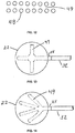
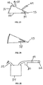
- Fig. 17 shows a channel 50 formed in a fold of the chamber wall.
- the channel 50 defines a space that opens directly to the treatment space 24.
- the space preferably opens to the treatment space 24 over the entire length of the channel 50.
- the walls of the fold can be configured with structures that prevent the collapse of such space, and ensure continuous open space for the distribution and maintenance of negative pressure, and the passage of liquid, gas, and other material.
- FIG. 18a shows engineered structures 52 that prevent the total collapse of the fold, and ensure continuous channel space 51. All channel spaces created on the interior surface of the chamber wall or by means of folds function as means to increase the effectiveness of distributing and maintaining negative pressure within the chamber, and also as means to enhance the effectiveness of removing gas, liquid, wound fluid, debris, and other materials from the chamber treatment space.
- Fig. 18b shows an embodiment similar to the embodiment shown in Fig. 17 with the addition of engineered raised structures 52 on opposite sides of the fold.
- the engineered structures 52 are provided so that the fold will not collapse to the point where all of its interior surfaces form a tight seal against the movement of negative pressure. However, some of the interior surfaces, such as those adjacent to the fold, preferably contact the wound to provide stimulation as discussed above.
- the folds described in the previous embodiments are preferably formed at certain defined areas by molding or embossing the surfaces of the chamber 22.
- Fig. 19 shows a wound chamber device 120 for delivering negative pressure and therapeutic substances in the form of a tube that can be placed over a limb.
- the wound chamber device 120 is generally cylindrical and includes an open end and a closed end. The open end is preferably sealed with a cuff or collar (not shown), and the open end may include adhesive on the interior surface.
- the wound chamber device 120 includes engineered structures 40 and channels 49 on the interior surface of the chamber wall.
- the wound chamber device 120 may also include folds and channels as described above.
- a fluid collector 60 may be positioned on the tube 32 between the chamber 22 and the suction device 34.
- the collector 60 is intended to receive fluid extracted from the chamber space 24 and debris or material from the wound and store such materials for eventual disposal.
- the collector 60 may be detachable from the tube 32, in order to replace a full collector with an empty collector.
- Suction for the wound treatment device is provided by a suction device 34, which may be a pump that is connected and disconnected to the chamber device by appropriate connectors.
- a suction device 34 may be a pump that is connected and disconnected to the chamber device by appropriate connectors.
- the hand-powered device may be a squeeze bulb that provides suction by means of the energy stored in the material of its construction.
- the suction device may be powered by springs that are compressed by the user. The springs can be selected to produce the clinically desired level of negative pressure. The amount of suction provided by these suction devices is therefore dependent on the level of force generated by squeezed material or the springs.
- the hand powered device preferably cannot produce a high level of suction that may cause an adverse effect to wound healing.
- a suction device 61 in the form of a bulb constructed of a deformable material that stores the energy of deformation may be used.
- the tube 32 communicates with the interior of the suction device 61.
- a one-way exhaust valve 62 also communicates with the interior of the suction device 61.
- air within the device is expelled through the exhaust valve 62.
- a portion of the energy used to deform the suction device 61 is stored in the material of which it is constructed, thus maintaining suction within the device, as well as within the tube 32 and the chamber space 24.
- the bulb is selected and engineered to maintain a constant force and to maintain the clinically desired level of negative pressure within chamber space 24.
- Fluid from the wound 30 can flow through the tube 32 into the suction device 61 where it can be stored prior to disposal. Once the suction device is full of fluid, the production of negative pressure ceases.
- the fluid capacity of the suction device thus operates as a safety shut-off mechanism without the need for electronic sensors and controls.
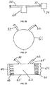
- Fig. 22 shows an alternative suction device 63, consisting of flexible sides 64 and rigid sides 65.
- Compression springs 66 are located within suction device 63.
- the tube 32 and the exhaust valve 62 both communicate with the interior of the suction device 63.
- the springs 66 are compressed and air within the device is expelled through a one-way exhaust valve 62 thus maintaining suction within the device, as well as within the tube 32 and the chamber space 24.
- the springs 66 are selected and engineered to maintain a constant force against rigid sides 65, and to maintain the clinically desired level of negative pressure within chamber space 24. Fluid from the wound 30 can flow through the tube 32 into the suction device 63 where it can be stored prior to disposal of the entire device 63. This suction device will also cease operating when it is filled with fluid.
- Fig. 23 shows an alternative suction device 70, consisting of rigid sides 72, joined by hinge 73, and flexible side 71.
- a torsional spring 74 is attached to either the interior or the exterior of rigid sides 72.
- the tube 32 and the exhaust valve 62 both communicate with the interior of the suction device 70.
- the spring 74 is selected and made to maintain a force against rigid sides 72 to maintain the clinically desired level of negative pressure within chamber space 24. Fluid from the wound 30 can flow through the tube 32 into the suction device 70 where it can be stored prior to disposal of the entire device.
- Fig. 24 shows the device of Fig. 27 where the torsional spring 74 has been replaced by a flat spring 78.
- fluid may flow from the wound to the suction device, where it may be collected and stored for eventual disposal.
- a separate fluid collector such as the fluid collector 60 in Fig. 20 , can be positioned between the chamber and the suction device. Once the suction device has expanded to its original shape, suction ceases. The suction device will not continue to operate, and can be disconnected and disposed of. If treatment is to be continued, a new suction device can be connected and activated.
- Fig. 25 is a sectional view of a trap 80 and a filter 82 interposed between the suction device 34 and the exhaust valve 62 for the purpose of preventing the expulsion of liquids or aerosols from the suction device.
- the present invention can be engineered to operate at vanous levels of negative pressure, in accordance with clinical procedures.
- the commonly accepted range of negative pressure is between 3,400 and 13,800 Pa (.5 and 2 psi).
- the device of the present invention operates efficiently in this range.
- the chamber material conforms to the shape of the wound, and the engineered structures maintain their shape and functionality.
- the chamber can be engineered to operate at higher levels of negative pressure.
- the operating pressure of the device may be higher than the commonly accepted range; that is, the device may operate at a pressure close to 0 Pa (0 psi) before suction ceases.
- the present invention preferably provides continuous negative pressure, but in practice there may be periods of time when negative pressure is not being produced.
- a care giver could provide a program of intermittent negative pressure by manually turning on and off the negative pressure system.
- the source of negative pressure may be controlled to produce intermittent negative pressure.
- the motor may include a controller that is programmed to intermittently provide negative pressure.
- a wound was created in a sample of animal cadaver tissue.
- a pressure sensor was installed in the tissue at the center of the wound.
- a wound chamber device with raised engineered structures on the interior chamber wall was sealed to the skin around the wound.
- a tube from the chamber device was connected to a source of suction capable of delivering a range of negative pressure. The amount of negative pressure measured at the suction source was compared to the measurement at the center of the wound, in order to determine the effectiveness of the device with respect to the distribution of negative pressure to the wound.
- a patient with a full-thickness skin wound was treated with a wound chamber negative pressure device connected to a hand-powered suction pump.
- the interior surface of the chamber contained embossed raised structures.
- the area around the wound was treated with normal skin disinfectants.
- the backing from the adhesive base of the chamber was removed, and the chamber was sealed to the normal skin around the wound.
- the tube was connected to a modified squeeze bulb with an inlet port for fluid, and an exhaust port through which air can be expelled from the bulb.
- a negative pressure of 13,800 Pa (2 psi) was established and maintained within the chamber. After the first 24 hours of treatment, the squeeze bulb had expanded to approximately half of its normal size.
- the bulb was compressed again to its fully flattened configuration.
- the bulb remained in such configuration for an additional 12 hours, at which point the chamber was removed.
- the wound showed healthy granulation tissue and progressed to heal rapidly and with minimal scarring.
- the device produced no adverse effects on the wound or the surrounding skin.
- the device of the present invention is preferably simplified and lightweight.
- the patient is not restricted to a source of electricity or a battery pack.
- the system can be worn with ease, so that the patient's mobility is not otherwise compromised.
- the wound interface appliance can be applied quickly without the need for custom fitting and construction.
- the device preferably does not leak due to the smooth adhesive base, eliminating the need for constant suction from an electric pump with sophisticated controls and safety measure.
- the inner surfaces of the chamber are generally non-porous and nonadherent to prevent any interaction with the wound tissue.
- the suction pump preferably has built-in safety limitations on force of suction, duration of operation, and overfilling of the collector for wound fluid.
Landscapes
- Health & Medical Sciences (AREA)
- Heart & Thoracic Surgery (AREA)
- General Health & Medical Sciences (AREA)
- Engineering & Computer Science (AREA)
- Biomedical Technology (AREA)
- Life Sciences & Earth Sciences (AREA)
- Animal Behavior & Ethology (AREA)
- Vascular Medicine (AREA)
- Public Health (AREA)
- Veterinary Medicine (AREA)
- Anesthesiology (AREA)
- Hematology (AREA)
- Surgical Instruments (AREA)
- Media Introduction/Drainage Providing Device (AREA)
- Massaging Devices (AREA)
Applications Claiming Priority (2)
| Application Number | Priority Date | Filing Date | Title |
|---|---|---|---|
| US93159907P | 2007-05-24 | 2007-05-24 | |
| PCT/US2008/064897 WO2008154158A2 (en) | 2007-05-24 | 2008-05-27 | Woundtreatment device employing negative pressure |
Publications (3)
| Publication Number | Publication Date |
|---|---|
| EP2157948A2 EP2157948A2 (en) | 2010-03-03 |
| EP2157948A4 EP2157948A4 (en) | 2014-01-22 |
| EP2157948B1 true EP2157948B1 (en) | 2017-02-15 |
Family
ID=40130427
Family Applications (1)
| Application Number | Title | Priority Date | Filing Date |
|---|---|---|---|
| EP08756312.8A Active EP2157948B1 (en) | 2007-05-24 | 2008-05-27 | Wound treatment device employing negative pressure |
Country Status (8)
| Country | Link |
|---|---|
| US (6) | US8632523B2 (enExample) |
| EP (1) | EP2157948B1 (enExample) |
| JP (2) | JP5642539B2 (enExample) |
| CN (2) | CN101784244B (enExample) |
| AU (2) | AU2008262140B2 (enExample) |
| CA (1) | CA2688167C (enExample) |
| ES (1) | ES2625463T3 (enExample) |
| WO (1) | WO2008154158A2 (enExample) |
Families Citing this family (150)
| Publication number | Priority date | Publication date | Assignee | Title |
|---|---|---|---|---|
| US9820888B2 (en) | 2006-09-26 | 2017-11-21 | Smith & Nephew, Inc. | Wound dressing |
| US8641691B2 (en) | 2006-09-28 | 2014-02-04 | Smith & Nephew, Inc. | Portable wound therapy system |
| US11511094B2 (en) | 2006-11-21 | 2022-11-29 | Mark R. Moore | Apparatus and method for deploying a surgical preparation |
| CN101784244B (zh) * | 2007-05-24 | 2014-07-16 | 应用纸巾技术有限公司 | 利用负压的伤口处理装置 |
| AU2008310819B2 (en) | 2007-10-10 | 2013-06-27 | Wake Forest University Health Sciences | Devices and methods for treating spinal cord tissue |
| GB0723855D0 (en) | 2007-12-06 | 2008-01-16 | Smith & Nephew | Apparatus and method for wound volume measurement |
| GB2455962A (en) | 2007-12-24 | 2009-07-01 | Ethicon Inc | Reinforced adhesive backing sheet, for plaster |
| RU2010135033A (ru) | 2008-03-05 | 2012-04-10 | КейСиАй Лайсензинг Инк. (US) | Повязка и способ приложения пониженного давления к участку ткани и сбора и хранения текучей среды от участка ткани |
| US9033942B2 (en) | 2008-03-07 | 2015-05-19 | Smith & Nephew, Inc. | Wound dressing port and associated wound dressing |
| US8298200B2 (en) | 2009-06-01 | 2012-10-30 | Tyco Healthcare Group Lp | System for providing continual drainage in negative pressure wound therapy |
| GB0804654D0 (en) * | 2008-03-13 | 2008-04-16 | Smith & Nephew | Vacuum closure device |
| KR20110033264A (ko) | 2008-07-11 | 2011-03-30 | 케이씨아이 라이센싱 인코포레이티드 | 상처 치료용 수동식 감압 시스템 |
| US9289193B2 (en) | 2008-07-18 | 2016-03-22 | Wake Forest University Health Sciences | Apparatus and method for cardiac tissue modulation by topical application of vacuum to minimize cell death and damage |
| GB0902368D0 (en) | 2009-02-13 | 2009-04-01 | Smith & Nephew | Wound packing |
| US20100324516A1 (en) | 2009-06-18 | 2010-12-23 | Tyco Healthcare Group Lp | Apparatus for Vacuum Bridging and/or Exudate Collection |
| DE102009031992A1 (de) * | 2009-07-06 | 2011-01-13 | Paul Hartmann Ag | Vorrichtung zur Unterdrucktherapie von Wunden |
| US8801685B2 (en) | 2009-12-22 | 2014-08-12 | Smith & Nephew, Inc. | Apparatuses and methods for negative pressure wound therapy |
| US9358158B2 (en) | 2010-03-16 | 2016-06-07 | Kci Licensing, Inc. | Patterned neo-epithelialization dressings, systems, and methods |
| US8814842B2 (en) | 2010-03-16 | 2014-08-26 | Kci Licensing, Inc. | Delivery-and-fluid-storage bridges for use with reduced-pressure systems |
| USRE48117E1 (en) | 2010-05-07 | 2020-07-28 | Smith & Nephew, Inc. | Apparatuses and methods for negative pressure wound therapy |
| GB201015656D0 (en) | 2010-09-20 | 2010-10-27 | Smith & Nephew | Pressure control apparatus |
| JP5881735B2 (ja) | 2010-12-22 | 2016-03-09 | スミス アンド ネフュー インコーポレーテッド | 陰圧創傷治療のための装置および方法 |
| USD714433S1 (en) | 2010-12-22 | 2014-09-30 | Smith & Nephew, Inc. | Suction adapter |
| GB2488749A (en) | 2011-01-31 | 2012-09-12 | Systagenix Wound Man Ip Co Bv | Laminated silicone coated wound dressing |
| MX358022B (es) | 2011-02-04 | 2018-08-02 | Univ Massachusetts | Dispositivo para cierre de heridas por presión negativa. |
| US9421132B2 (en) | 2011-02-04 | 2016-08-23 | University Of Massachusetts | Negative pressure wound closure device |
| GB201106491D0 (en) | 2011-04-15 | 2011-06-01 | Systagenix Wound Man Ip Co Bv | Patterened silicone coating |
| CN103619366B (zh) | 2011-04-15 | 2018-02-16 | 马萨诸塞州大学 | 外科腔引流和闭合系统 |
| EP2567681B1 (de) * | 2011-09-09 | 2014-11-12 | Paul Hartmann AG | Wundauflage für den Abdominalbereich |
| WO2013049834A2 (en) * | 2011-09-30 | 2013-04-04 | Eksigent Technologies, Llc | Electrokinetic pump based wound treatment system and methods |
| US9084845B2 (en) | 2011-11-02 | 2015-07-21 | Smith & Nephew Plc | Reduced pressure therapy apparatuses and methods of using same |
| JP5701998B2 (ja) * | 2011-12-01 | 2015-04-15 | 株式会社東芝 | 二酸化炭素回収装置、二酸化炭素回収方法およびアミン化合物回収方法 |
| US10940047B2 (en) | 2011-12-16 | 2021-03-09 | Kci Licensing, Inc. | Sealing systems and methods employing a hybrid switchable drape |
| US9861532B2 (en) | 2011-12-16 | 2018-01-09 | Kci Licensing, Inc. | Releasable medical drapes |
| US10695471B2 (en) * | 2012-02-13 | 2020-06-30 | Phase One Health, Llc | Wound dressing apparatus |
| EP2838607A4 (en) | 2012-04-12 | 2015-12-30 | Univ Wake Forest Health Sciences | DESIGN OF A PIPE FOR A PERIPHERAL NERVOUS REPLACEMENT |
| EP2852333B1 (en) | 2012-05-22 | 2021-12-15 | Smith & Nephew plc | Apparatuses for wound therapy |
| US9844472B2 (en) | 2012-05-22 | 2017-12-19 | Smith & Nephew Plc | Wound closure device |
| MX2014014325A (es) | 2012-05-24 | 2015-08-06 | Smith & Nephew Inc | Dispositivos y metodos para tratar y cerrar heridas con presion negativa. |
| EP2872085A1 (en) | 2012-07-16 | 2015-05-20 | Smith&Nephew, Inc. | Negative pressure wound closure device |
| WO2014066724A1 (en) | 2012-10-26 | 2014-05-01 | Wake Forest University Health Sciences | Novel nanofiber-based graft for heart valve replacement and methods of using the same |
| AU2013344686B2 (en) | 2012-11-16 | 2018-06-21 | Solventum Intellectual Properties Company | Medical drape with pattern adhesive layers and method of manufacturing same |
| GB201222770D0 (en) | 2012-12-18 | 2013-01-30 | Systagenix Wound Man Ip Co Bv | Wound dressing with adhesive margin |
| EP2939602B1 (en) * | 2012-12-25 | 2021-04-14 | Fuso Pharmaceutical Industries, Ltd. | Hemostatic agent applicator |
| WO2014116783A1 (en) * | 2013-01-24 | 2014-07-31 | The Cleveland Clinic Foundation | Wound cover apparatus and method |
| BR112015021854A2 (pt) | 2013-03-13 | 2017-07-18 | Smith & Nephew Inc | dispositivo de fechamento de ferida com pressão negativa e sistemas e métodos de uso no tratamento de feridas com pressão negativa |
| WO2014140578A1 (en) | 2013-03-14 | 2014-09-18 | Smith & Nephew Plc | Compressible wound fillers and systems and methods of use in treating wounds with negative pressure |
| US9283118B2 (en) | 2013-03-14 | 2016-03-15 | Kci Licensing, Inc. | Absorbent dressing with hybrid drape |
| WO2014144762A2 (en) * | 2013-03-15 | 2014-09-18 | The General Hospital Corporation | Method and apparatus for wound dressing |
| CA2918157A1 (en) | 2013-07-16 | 2015-01-22 | Smith & Nephew Plc | Apparatus for wound therapy |
| WO2015030963A1 (en) | 2013-08-26 | 2015-03-05 | Kci Licensing, Inc. | Dressing interface with moisture controlling feature and sealing function |
| CN106170275B (zh) | 2013-10-21 | 2021-05-07 | 史密夫和内修有限公司 | 负压伤口闭合装置 |
| WO2015065742A1 (en) | 2013-10-28 | 2015-05-07 | Kci Licensing, Inc. | Hybrid sealing tape |
| EP3257486B1 (en) | 2013-10-30 | 2019-06-05 | KCI Licensing, Inc. | Condensate absorbing and dissipating system |
| WO2015065615A1 (en) | 2013-10-30 | 2015-05-07 | Kci Licensing, Inc. | Absorbent conduit and system |
| US9956120B2 (en) | 2013-10-30 | 2018-05-01 | Kci Licensing, Inc. | Dressing with sealing and retention interface |
| CA2926932C (en) | 2013-10-30 | 2021-10-05 | Kci Licensing, Inc. | Dressing with differentially sized perforations |
| EP3096728B1 (en) | 2014-01-21 | 2021-12-15 | Smith & Nephew plc | Collapsible dressing for negative pressure wound treatment |
| RU2016133734A (ru) | 2014-01-21 | 2018-03-02 | СМИТ ЭНД НЕФЬЮ ПиЭлСи | Устройства для лечения ран |
| WO2015130471A1 (en) | 2014-02-28 | 2015-09-03 | Kci Licensing, Inc. | Hybrid drape having a gel-coated perforated mesh |
| US11026844B2 (en) | 2014-03-03 | 2021-06-08 | Kci Licensing, Inc. | Low profile flexible pressure transmission conduit |
| US10531977B2 (en) | 2014-04-17 | 2020-01-14 | Coloplast A/S | Thermoresponsive skin barrier appliances |
| EP3137029B1 (en) | 2014-05-02 | 2020-09-09 | KCI Licensing, Inc. | Fluid storage devices, systems, and methods |
| EP3597159B1 (en) | 2014-06-05 | 2021-08-04 | 3M Innovative Properties Company | Dressing with fluid acquisition and distribution characteristics |
| EP3233001B1 (en) | 2014-12-17 | 2020-06-17 | KCI Licensing, Inc. | Dressing with offloading capability |
| EP3288509B1 (en) | 2015-04-29 | 2022-06-29 | Smith & Nephew, Inc | Negative pressure wound closure device |
| WO2016182977A1 (en) | 2015-05-08 | 2016-11-17 | Kci Licensing, Inc. | Low acuity dressing with integral pump |
| WO2017040045A1 (en) | 2015-09-01 | 2017-03-09 | Kci Licensing, Inc. | Dressing with increased apposition force |
| EP3892310B1 (en) | 2015-09-17 | 2025-10-29 | Solventum Intellectual Properties Company | Hybrid silicone and acrylic adhesive cover for use with wound treatment |
| US20220087800A1 (en) * | 2015-10-12 | 2022-03-24 | Mark WOLGIN | Negative Pressure Wound Therapy for Treatment of Periodontal Disease |
| US10575991B2 (en) | 2015-12-15 | 2020-03-03 | University Of Massachusetts | Negative pressure wound closure devices and methods |
| US10814049B2 (en) | 2015-12-15 | 2020-10-27 | University Of Massachusetts | Negative pressure wound closure devices and methods |
| US11141100B2 (en) | 2015-12-23 | 2021-10-12 | Coloplast A/S | Moisture assessment system and method for wound care |
| EP3397220B1 (en) * | 2015-12-30 | 2020-07-01 | Smith & Nephew plc | Negative pressure wound therapy apparatus |
| CA3030152A1 (en) | 2016-07-08 | 2018-01-11 | Convatec Technologies Inc. | Flexible negative pressure system |
| EP3506865B1 (en) | 2016-08-30 | 2021-10-06 | Smith & Nephew plc | Systems for applying reduced pressure therapy |
| JP6361844B1 (ja) * | 2016-09-23 | 2018-07-25 | 株式会社村田製作所 | 陰圧閉鎖療法器具 |
| EP3518847B1 (en) | 2016-09-27 | 2023-03-01 | Smith & Nephew plc | Wound closure devices with dissolvable portions |
| WO2018085457A1 (en) | 2016-11-02 | 2018-05-11 | Smith & Nephew Inc. | Wound closure devices |
| WO2018119442A1 (en) | 2016-12-22 | 2018-06-28 | Applied Tissue Technologies Llc | Devices and methods for wound treatment |
| US11491265B2 (en) | 2017-02-22 | 2022-11-08 | Cornell University | Mechanical vacuum dressing for mechanically managing, protecting and suctioning small incisional wounds |
| WO2018231815A2 (en) * | 2017-06-12 | 2018-12-20 | Kci Licensing, Inc. | Fabric wound filler |
| JP7179022B2 (ja) | 2017-06-13 | 2022-11-28 | スミス アンド ネフュー ピーエルシー | 創傷閉鎖装置および使用方法 |
| EP3638169B1 (en) | 2017-06-13 | 2024-11-13 | Smith & Nephew PLC | Collapsible structure and method of use |
| WO2018229011A1 (en) | 2017-06-14 | 2018-12-20 | Smith & Nephew Plc | Collapsible structure for wound closure and method of use |
| EP3638173A1 (en) | 2017-06-14 | 2020-04-22 | Smith & Nephew, Inc | Control of wound closure and fluid removal management in wound therapy |
| US11724020B2 (en) | 2017-06-14 | 2023-08-15 | Smith & Nephew Plc | Collapsible sheet for wound closure and method of use |
| EP3638332A1 (en) | 2017-06-14 | 2020-04-22 | Smith & Nephew, Inc | Fluid removal management and control of wound closure in wound therapy |
| WO2019020544A1 (en) | 2017-07-27 | 2019-01-31 | Smith & Nephew Plc | CUSTOM WELD CLOSURE DEVICE AND METHOD OF USE |
| US11590030B2 (en) | 2017-08-07 | 2023-02-28 | Smith & Nephew Plc | Wound closure device with protective layer and method of use |
| WO2019042790A1 (en) | 2017-08-29 | 2019-03-07 | Smith & Nephew Plc | SYSTEMS AND METHODS FOR MONITORING WOUND CLOSURE |
| CN111432855B (zh) | 2017-12-06 | 2024-02-23 | 康奈尔大学 | 具有提高的泵效率、自动压力指示器和自动压力限制器的手动操作的负压伤口治疗(npwt)绷带 |
| US10799385B2 (en) | 2017-12-22 | 2020-10-13 | Coloplast A/S | Ostomy appliance with layered base plate |
| EP4245273A3 (en) | 2017-12-22 | 2023-11-08 | Coloplast A/S | Base plate and sensor assembly of an ostomy system having a leakage sensor |
| EP4275663A3 (en) | 2017-12-22 | 2024-01-17 | Coloplast A/S | Moisture detecting base plate for an ostomy appliance and a system for determining moisture propagation in a base plate and/or a sensor assembly part |
| AU2018391316B2 (en) | 2017-12-22 | 2024-05-02 | Coloplast A/S | Ostomy appliance with selective sensor points and related methods |
| WO2019120441A1 (en) * | 2017-12-22 | 2019-06-27 | Coloplast A/S | Sensor assembly part and a base plate for an ostomy appliance and a method for manufacturing a sensor assembly part and a base plate |
| WO2019120442A1 (en) | 2017-12-22 | 2019-06-27 | Coloplast A/S | Sensor assembly part and a base plate for an ostomy appliance and a device for connecting to a base plate or a sensor assembly part |
| US11471318B2 (en) | 2017-12-22 | 2022-10-18 | Coloplast A/S | Data collection schemes for a medical appliance and related methods |
| LT3727245T (lt) | 2017-12-22 | 2025-06-10 | Coloplast A/S | Ostomijos sistemos duomenų perdavimo schemos, ostomijos prietaiso stebėjimo įrenginys ir susiję būdai |
| WO2019120439A1 (en) | 2017-12-22 | 2019-06-27 | Coloplast A/S | Calibration methods for ostomy appliance tools |
| AU2018386861B2 (en) | 2017-12-22 | 2024-03-14 | Coloplast A/S | Ostomy appliance with angular leakage detection |
| JP7348184B2 (ja) | 2017-12-22 | 2023-09-20 | コロプラスト アクティーゼルスカブ | オストミーベースプレート及びセンサ組立体部分のためのヒンジを有する結合部 |
| US10500084B2 (en) | 2017-12-22 | 2019-12-10 | Coloplast A/S | Accessory devices of an ostomy system, and related methods for communicating leakage state |
| US10849781B2 (en) | 2017-12-22 | 2020-12-01 | Coloplast A/S | Base plate for an ostomy appliance |
| WO2019120427A1 (en) | 2017-12-22 | 2019-06-27 | Coloplast A/S | Sensor assembly part for an ostomy appliance and a method for manufacturing a sensor assembly part |
| WO2019120425A1 (en) | 2017-12-22 | 2019-06-27 | Coloplast A/S | Ostomy appliance system, monitor device, and method of monitoring an ostomy appliance |
| EP3727244B1 (en) | 2017-12-22 | 2025-08-20 | Coloplast A/S | Sensor assembly part, base plate and monitor device of an ostomy system and associated method |
| EP3727231B2 (en) | 2017-12-22 | 2025-03-12 | Coloplast A/S | Processing schemes for an ostomy system, monitor device for an ostomy appliance and related methods |
| CN111447894B (zh) | 2017-12-22 | 2024-07-12 | 科洛普拉斯特公司 | 用于造口术器具的底板以及用于制造底板的方法 |
| US11534323B2 (en) | 2017-12-22 | 2022-12-27 | Coloplast A/S | Tools and methods for placing a medical appliance on a user |
| US11865029B2 (en) | 2017-12-22 | 2024-01-09 | Coloplast A/S | Monitor device of a medical system having a connector for coupling to both a base plate and an accessory device |
| US11986418B2 (en) | 2017-12-22 | 2024-05-21 | Coloplast A/S | Medical system and monitor device with angular leakage detection |
| WO2019120443A1 (en) | 2017-12-22 | 2019-06-27 | Coloplast A/S | Sensor assembly part and a base plate for an ostomy appliance and a method for manufacturing a base plate or a sensor assembly part |
| EP3727228B1 (en) | 2017-12-22 | 2022-06-15 | Coloplast A/S | Base plate and a sensor assembly part for an ostomy appliance and a method for manufacturing a base plate and sensor assembly part |
| JP7372919B2 (ja) | 2017-12-22 | 2023-11-01 | コロプラスト アクティーゼルスカブ | 動作状態を通信するオストミーシステムの付属デバイス及び関連方法 |
| JP7472022B2 (ja) | 2017-12-22 | 2024-04-22 | コロプラスト アクティーゼルスカブ | オストミー装具のためのベースプレート、モニタデバイス及びオストミー装具のためのシステム |
| US11998473B2 (en) | 2017-12-22 | 2024-06-04 | Coloplast A/S | Tools and methods for cutting holes in a medical appliance |
| WO2019161861A1 (en) | 2018-02-20 | 2019-08-29 | Coloplast A/S | Sensor assembly part and a base plate for an ostomy appliance and a device for connecting to a base plate and/or a sensor assembly part |
| US12029582B2 (en) | 2018-02-20 | 2024-07-09 | Coloplast A/S | Accessory devices of a medical system, and related methods for changing a medical appliance based on future operating state |
| EP3755283B1 (en) | 2018-02-20 | 2024-05-01 | Coloplast A/S | Sensor assembly part and a base plate and an ostomy pouch for an ostomy appliance and a device for connecting to a base plate and/or a sensor assembly part |
| LT3764960T (lt) | 2018-03-15 | 2024-01-10 | Coloplast A/S | Įtaisai ir būdai ostomijos prietaiso susidėvėjimo laikui nustatyti, remiantis vietos duomenimis |
| EP3764956B1 (en) | 2018-03-15 | 2022-05-11 | Coloplast A/S | Methods for managing remaining wear time of an ostomy appliance and related accessory devices |
| WO2019174697A1 (en) | 2018-03-15 | 2019-09-19 | Coloplast A/S | Apparatus and methods for navigating ostomy appliance user to changing room |
| WO2019174698A1 (en) | 2018-03-15 | 2019-09-19 | Coloplast A/S | Methods of configuring ostomy notifications and related accessory devices |
| GB201811449D0 (en) | 2018-07-12 | 2018-08-29 | Smith & Nephew | Apparatuses and methods for negative pressure wound therapy |
| EP3829515A1 (en) | 2018-08-01 | 2021-06-09 | KCI Licensing, Inc. | Soft-tissue treatment with negative pressure |
| CN112567221B (zh) | 2018-08-15 | 2024-06-25 | 科洛普拉斯特公司 | 造口术系统的附属装置、以及用于问题识别的相关方法 |
| GB2592502B (en) | 2018-09-28 | 2023-03-22 | Smith & Nephew | Optical fibers for optically sensing through wound dressings |
| EP3893825A1 (en) | 2018-12-13 | 2021-10-20 | University of Massachusetts | Negative pressure wound closure devices and methods |
| BR112021011637A2 (pt) | 2018-12-20 | 2021-09-08 | Coloplast A/S | Método para classificar uma condição de ostomia |
| EP4257035A3 (en) | 2018-12-20 | 2024-01-03 | Coloplast A/S | Ostomy condition classification with masking, devices and related methods |
| EP3917467B1 (en) | 2019-01-31 | 2025-07-16 | Coloplast A/S | A sensor patch for an ostomy appliance |
| EP3917466B1 (en) | 2019-01-31 | 2023-08-09 | Coloplast A/S | Stomal sensor patch |
| US11612512B2 (en) | 2019-01-31 | 2023-03-28 | Coloplast A/S | Moisture detecting base plate for an ostomy appliance and a system for determining moisture propagation in a base plate and/or a sensor assembly part |
| EP3917465A1 (en) | 2019-01-31 | 2021-12-08 | Coloplast A/S | Application of a stomal sensor patch |
| WO2020173534A1 (en) | 2019-02-28 | 2020-09-03 | Coloplast A/S | A sensor patch for attachment to a base plate |
| US12268805B2 (en) * | 2019-03-29 | 2025-04-08 | Kci Licensing, Inc. | Dressing with integrated pump and releasably coupled pump actuator |
| WO2020245656A1 (en) | 2019-06-03 | 2020-12-10 | Convatec Limited | Methods and devices to disrupt and contain pathogens |
| CN110522419B (zh) * | 2019-09-03 | 2021-11-02 | 苏州元禾医疗器械有限公司 | 一种创面修复程度检测装置及其制造方法 |
| US11696962B2 (en) | 2019-10-16 | 2023-07-11 | Mark R. Moore | Apparatus and method for deploying a preoperative skin disinfection device with integrated drape |
| WO2021142293A1 (en) * | 2020-01-10 | 2021-07-15 | Applied Tissue Technologies Llc | Devices and methods for negative pressure therapy |
| GB202000574D0 (en) | 2020-01-15 | 2020-02-26 | Smith & Nephew | Fluidic connectors for negative pressure wound therapy |
| JP2023521537A (ja) * | 2020-02-13 | 2023-05-25 | ペイレッティ エンリコ | 外科手術および補助外科手術用の滅菌ヘッドセット装置 |
| EP4512377A3 (en) | 2020-04-14 | 2025-04-30 | Coloplast A/S | METHOD FOR A MONITORING DEVICE FOR A PERSONAL CARE SYSTEM |
| EP4132440B1 (en) * | 2020-05-05 | 2024-07-10 | KCI Manufacturing Unlimited Company | Tissue interface for negative pressure and instillation therapy |
| US20220008632A1 (en) * | 2020-07-13 | 2022-01-13 | Wellness Allied Inc | Cupping auxiliary consumable, cupping kit, and cupping method |
| US12239572B2 (en) | 2021-07-29 | 2025-03-04 | Critical Innovations, LLC | Wound treatment device |
| CN115607758B (zh) * | 2022-12-01 | 2023-04-04 | 中国医学科学院北京协和医院 | 一种引流漏液收集机构以及引流管装置 |
| WO2024171120A1 (en) * | 2023-02-16 | 2024-08-22 | Fisher & Paykel Healthcare Limited | "apparatus for supplying fluid to a tissue area" |
Family Cites Families (47)
| Publication number | Priority date | Publication date | Assignee | Title |
|---|---|---|---|---|
| US2283089A (en) * | 1941-05-29 | 1942-05-12 | Blackhawk Mfg Co | Hydraulic wedge assembly |
| JPS5122888B2 (enExample) | 1971-12-07 | 1976-07-13 | ||
| JPS5122888A (enExample) | 1974-08-20 | 1976-02-23 | ||
| US4469092A (en) | 1982-09-27 | 1984-09-04 | Marshall Walter D | Scalp stimulating system |
| ES2019457B3 (es) * | 1987-06-22 | 1991-06-16 | Takeda Chemical Industries Ltd | Equipo de succion para operacion medica. |
| DE69029275T2 (de) | 1989-12-14 | 1997-06-12 | Eriksson Elof | Behandlungssystem für wunden und andere fehler |
| US5312385A (en) | 1991-10-09 | 1994-05-17 | University Of Pittsburgh | Device for protected pulse irrigation |
| US7198046B1 (en) | 1991-11-14 | 2007-04-03 | Wake Forest University Health Sciences | Wound treatment employing reduced pressure |
| US5636643A (en) * | 1991-11-14 | 1997-06-10 | Wake Forest University | Wound treatment employing reduced pressure |
| US5807290A (en) | 1992-05-29 | 1998-09-15 | South Glamorgan Health Authority | Inflatable supports |
| US5447504A (en) | 1993-05-03 | 1995-09-05 | Baker; Gregg R. | Misting apparatus for the treatment of injured areas and method therefor |
| US5437602A (en) | 1993-08-13 | 1995-08-01 | Atm Wound Management, Inc. | Isolator bag for therapeutic treatments of human limbs |
| US5437651A (en) * | 1993-09-01 | 1995-08-01 | Research Medical, Inc. | Medical suction apparatus |
| US5527265A (en) | 1994-08-16 | 1996-06-18 | Mckeel; William H. | Orthopedic airflow cast pad and method |
| WO1996034638A1 (en) * | 1995-05-02 | 1996-11-07 | Medela, Inc. | Foot-powered breastmilk pump with removable piston pump |
| DE19517699C2 (de) | 1995-05-13 | 1999-11-04 | Wilhelm Fleischmann | Vorrichtung zur Vakuumversiegelung einer Wunde |
| US5605534A (en) | 1995-12-26 | 1997-02-25 | Hutchison; Jeffrey W. | Shower guard for IV site |
| US6053882A (en) | 1996-08-15 | 2000-04-25 | Johansen; Jan S. | Cast ventilation sleeve |
| US6290685B1 (en) * | 1998-06-18 | 2001-09-18 | 3M Innovative Properties Company | Microchanneled active fluid transport devices |
| GB9719520D0 (en) * | 1997-09-12 | 1997-11-19 | Kci Medical Ltd | Surgical drape and suction heads for wound treatment |
| US7273054B2 (en) | 1997-09-12 | 2007-09-25 | Kci Licensing, Inc. | Surgical drape and head for wound treatment |
| US6458109B1 (en) * | 1998-08-07 | 2002-10-01 | Hill-Rom Services, Inc. | Wound treatment apparatus |
| GB2348136B (en) * | 1999-03-24 | 2003-06-04 | Johnson & Johnson Medical Ltd | Wound dressings having low adherency |
| GB9926538D0 (en) | 1999-11-09 | 2000-01-12 | Kci Medical Ltd | Multi-lumen connector |
| US6824533B2 (en) * | 2000-11-29 | 2004-11-30 | Hill-Rom Services, Inc. | Wound treatment apparatus |
| WO2001037922A2 (en) * | 1999-11-29 | 2001-05-31 | Hill-Rom Services, Inc. | Wound treatment apparatus |
| JP2001243955A (ja) * | 1999-12-28 | 2001-09-07 | Wilson Greatbatch Ltd | 連続分解化学反応による混合金属酸化物カソード活物質の調製 |
| US7356504B2 (en) * | 2000-05-01 | 2008-04-08 | The Olsen Group | Methods for determining value at risk |
| US6685681B2 (en) * | 2000-11-29 | 2004-02-03 | Hill-Rom Services, Inc. | Vacuum therapy and cleansing dressing for wounds |
| US6855135B2 (en) | 2000-11-29 | 2005-02-15 | Hill-Rom Services, Inc. | Vacuum therapy and cleansing dressing for wounds |
| GB0115054D0 (en) | 2001-06-20 | 2001-08-15 | Recuperatio Ltd | Fluid transfer device |
| US7004915B2 (en) | 2001-08-24 | 2006-02-28 | Kci Licensing, Inc. | Negative pressure assisted tissue treatment system |
| ITRM20010669A1 (it) * | 2001-11-09 | 2003-05-09 | Optikon 2000 Spa | Cassetta infusione aspirazione (i/a) con sistema di aspirazione sia mediante pompa peristaltica o comunque volumetrica che mediante pompa pr |
| WO2003057070A2 (en) * | 2001-12-26 | 2003-07-17 | Hill-Rom Services Inc. | Vented vacuum bandage and method |
| US7520872B2 (en) | 2002-09-13 | 2009-04-21 | Neogen Technologies, Inc. | Closed wound drainage system |
| US7815616B2 (en) * | 2002-09-16 | 2010-10-19 | Boehringer Technologies, L.P. | Device for treating a wound |
| GB0325126D0 (en) | 2003-10-28 | 2003-12-03 | Smith & Nephew | Apparatus with heat |
| US7128735B2 (en) | 2004-01-02 | 2006-10-31 | Richard Scott Weston | Reduced pressure wound treatment appliance |
| US7776028B2 (en) * | 2004-04-05 | 2010-08-17 | Bluesky Medical Group Incorporated | Adjustable overlay reduced pressure wound treatment system |
| US7884258B2 (en) | 2004-04-13 | 2011-02-08 | Boehringer Technologies, L.P. | Wound contact device |
| GB0508529D0 (en) * | 2005-04-27 | 2005-06-01 | Smith & Nephew | Sai with microstress |
| WO2005115523A1 (en) * | 2004-05-17 | 2005-12-08 | Applied Tissue Technologies Llc | Wound chamber with remote access portal |
| US7612247B2 (en) * | 2004-09-29 | 2009-11-03 | Oyaski Michael F | Wound alternative treatment system |
| US20060216171A1 (en) * | 2005-03-23 | 2006-09-28 | Alltrade Tools Llc | Hand held pump |
| JP5555828B2 (ja) * | 2005-06-29 | 2014-07-23 | アプライド ティッシュ テクノロジーズ リミテッド ライアビリティ カンパニー | 肢のための創傷チャンバ |
| CN105233350B (zh) * | 2006-10-13 | 2019-05-17 | 凯希特许有限公司 | 用于对低严重性伤口提供治疗的减压输送系统 |
| CN101784244B (zh) * | 2007-05-24 | 2014-07-16 | 应用纸巾技术有限公司 | 利用负压的伤口处理装置 |
-
2008
- 2008-05-27 CN CN200880024385.8A patent/CN101784244B/zh active Active
- 2008-05-27 WO PCT/US2008/064897 patent/WO2008154158A2/en not_active Ceased
- 2008-05-27 CN CN201410255520.7A patent/CN104014070B/zh active Active
- 2008-05-27 JP JP2010509587A patent/JP5642539B2/ja active Active
- 2008-05-27 EP EP08756312.8A patent/EP2157948B1/en active Active
- 2008-05-27 ES ES08756312.8T patent/ES2625463T3/es active Active
- 2008-05-27 CA CA2688167A patent/CA2688167C/en active Active
- 2008-05-27 US US12/601,394 patent/US8632523B2/en active Active
- 2008-05-27 AU AU2008262140A patent/AU2008262140B2/en active Active
-
2013
- 2013-11-27 US US14/092,004 patent/US9717829B2/en active Active
-
2014
- 2014-07-23 AU AU2014206144A patent/AU2014206144B2/en active Active
- 2014-10-29 JP JP2014220515A patent/JP6334364B2/ja active Active
- 2014-10-31 US US14/530,107 patent/US9693908B2/en active Active
-
2017
- 2017-06-30 US US15/638,629 patent/US20180235814A1/en not_active Abandoned
-
2020
- 2020-09-02 US US17/010,519 patent/US20210228416A1/en not_active Abandoned
-
2023
- 2023-10-11 US US18/378,900 patent/US20240041660A1/en not_active Abandoned
Non-Patent Citations (1)
| Title |
|---|
| None * |
Also Published As
| Publication number | Publication date |
|---|---|
| AU2008262140B2 (en) | 2014-04-24 |
| US20140088521A1 (en) | 2014-03-27 |
| EP2157948A4 (en) | 2014-01-22 |
| US20180235814A1 (en) | 2018-08-23 |
| JP5642539B2 (ja) | 2014-12-17 |
| AU2014206144B2 (en) | 2017-02-02 |
| US20240041660A1 (en) | 2024-02-08 |
| US9717829B2 (en) | 2017-08-01 |
| WO2008154158A2 (en) | 2008-12-18 |
| ES2625463T3 (es) | 2017-07-19 |
| US20110004168A1 (en) | 2011-01-06 |
| US9693908B2 (en) | 2017-07-04 |
| JP2010527713A (ja) | 2010-08-19 |
| EP2157948A2 (en) | 2010-03-03 |
| US8632523B2 (en) | 2014-01-21 |
| CN101784244B (zh) | 2014-07-16 |
| CA2688167C (en) | 2017-05-16 |
| AU2014206144A1 (en) | 2014-08-07 |
| CN104014070B (zh) | 2017-09-08 |
| CN101784244A (zh) | 2010-07-21 |
| WO2008154158A3 (en) | 2010-01-07 |
| US20210228416A1 (en) | 2021-07-29 |
| JP6334364B2 (ja) | 2018-05-30 |
| JP2015016389A (ja) | 2015-01-29 |
| CA2688167A1 (en) | 2008-12-18 |
| AU2008262140A1 (en) | 2008-12-18 |
| US20150119857A1 (en) | 2015-04-30 |
| CN104014070A (zh) | 2014-09-03 |
Similar Documents
| Publication | Publication Date | Title |
|---|---|---|
| EP2157948B1 (en) | Wound treatment device employing negative pressure | |
| US10967106B2 (en) | Wound therapy system and related methods therefor | |
| US8829263B2 (en) | Self contained wound dressing with micropump | |
| EP2859903B1 (en) | Apparatus for administering reduced pressure treatment to a tissue site | |
| WO2010093496A1 (en) | Wound therapy system with proportional valve mechanism | |
| KR20110056415A (ko) | 조직 부위에 감압을 작용하는 방법, 시스템 및 다층 드레싱 | |
| HK1141704B (en) | Wound treatment device employing negative pressure | |
| HK1141704A (en) | Wound treatment device employing negative pressure |
Legal Events
| Date | Code | Title | Description |
|---|---|---|---|
| PUAI | Public reference made under article 153(3) epc to a published international application that has entered the european phase |
Free format text: ORIGINAL CODE: 0009012 |
|
| 17P | Request for examination filed |
Effective date: 20091223 |
|
| AK | Designated contracting states |
Kind code of ref document: A2 Designated state(s): AT BE BG CH CY CZ DE DK EE ES FI FR GB GR HR HU IE IS IT LI LT LU LV MC MT NL NO PL PT RO SE SI SK TR |
|
| AX | Request for extension of the european patent |
Extension state: AL BA MK RS |
|
| REG | Reference to a national code |
Ref country code: HK Ref legal event code: DE Ref document number: 1141704 Country of ref document: HK |
|
| DAX | Request for extension of the european patent (deleted) | ||
| A4 | Supplementary search report drawn up and despatched |
Effective date: 20140102 |
|
| RIC1 | Information provided on ipc code assigned before grant |
Ipc: A61F 13/00 20060101AFI20131217BHEP Ipc: A61B 19/00 20060101ALI20131217BHEP Ipc: A61M 1/00 20060101ALI20131217BHEP |
|
| RAP1 | Party data changed (applicant data changed or rights of an application transferred) |
Owner name: APPLIED TISSUE TECHNOLOGIES LLC |
|
| 17Q | First examination report despatched |
Effective date: 20140902 |
|
| REG | Reference to a national code |
Ref country code: DE Ref legal event code: R079 Ref document number: 602008048757 Country of ref document: DE Free format text: PREVIOUS MAIN CLASS: A61F0013000000 Ipc: A61F0013020000 |
|
| RIC1 | Information provided on ipc code assigned before grant |
Ipc: A61M 1/00 20060101ALI20160204BHEP Ipc: A61F 13/00 20060101ALI20160204BHEP Ipc: A61F 13/02 20060101AFI20160204BHEP |
|
| GRAP | Despatch of communication of intention to grant a patent |
Free format text: ORIGINAL CODE: EPIDOSNIGR1 |
|
| INTG | Intention to grant announced |
Effective date: 20160318 |
|
| GRAS | Grant fee paid |
Free format text: ORIGINAL CODE: EPIDOSNIGR3 |
|
| GRAJ | Information related to disapproval of communication of intention to grant by the applicant or resumption of examination proceedings by the epo deleted |
Free format text: ORIGINAL CODE: EPIDOSDIGR1 |
|
| GRAL | Information related to payment of fee for publishing/printing deleted |
Free format text: ORIGINAL CODE: EPIDOSDIGR3 |
|
| GRAP | Despatch of communication of intention to grant a patent |
Free format text: ORIGINAL CODE: EPIDOSNIGR1 |
|
| INTC | Intention to grant announced (deleted) | ||
| INTG | Intention to grant announced |
Effective date: 20160906 |
|
| STAA | Information on the status of an ep patent application or granted ep patent |
Free format text: STATUS: GRANT OF PATENT IS INTENDED |
|
| GRAA | (expected) grant |
Free format text: ORIGINAL CODE: 0009210 |
|
| STAA | Information on the status of an ep patent application or granted ep patent |
Free format text: STATUS: THE PATENT HAS BEEN GRANTED |
|
| AK | Designated contracting states |
Kind code of ref document: B1 Designated state(s): AT BE BG CH CY CZ DE DK EE ES FI FR GB GR HR HU IE IS IT LI LT LU LV MC MT NL NO PL PT RO SE SI SK TR |
|
| REG | Reference to a national code |
Ref country code: GB Ref legal event code: FG4D Ref country code: CH Ref legal event code: EP |
|
| REG | Reference to a national code |
Ref country code: IE Ref legal event code: FG4D |
|
| REG | Reference to a national code |
Ref country code: AT Ref legal event code: REF Ref document number: 867486 Country of ref document: AT Kind code of ref document: T Effective date: 20170315 |
|
| REG | Reference to a national code |
Ref country code: DE Ref legal event code: R096 Ref document number: 602008048757 Country of ref document: DE |
|
| REG | Reference to a national code |
Ref country code: FR Ref legal event code: PLFP Year of fee payment: 10 |
|
| REG | Reference to a national code |
Ref country code: NL Ref legal event code: MP Effective date: 20170215 |
|
| REG | Reference to a national code |
Ref country code: LT Ref legal event code: MG4D |
|
| REG | Reference to a national code |
Ref country code: AT Ref legal event code: MK05 Ref document number: 867486 Country of ref document: AT Kind code of ref document: T Effective date: 20170215 |
|
| REG | Reference to a national code |
Ref country code: ES Ref legal event code: FG2A Ref document number: 2625463 Country of ref document: ES Kind code of ref document: T3 Effective date: 20170719 |
|
| PG25 | Lapsed in a contracting state [announced via postgrant information from national office to epo] |
Ref country code: GR Free format text: LAPSE BECAUSE OF FAILURE TO SUBMIT A TRANSLATION OF THE DESCRIPTION OR TO PAY THE FEE WITHIN THE PRESCRIBED TIME-LIMIT Effective date: 20170516 Ref country code: NO Free format text: LAPSE BECAUSE OF FAILURE TO SUBMIT A TRANSLATION OF THE DESCRIPTION OR TO PAY THE FEE WITHIN THE PRESCRIBED TIME-LIMIT Effective date: 20170515 Ref country code: HR Free format text: LAPSE BECAUSE OF FAILURE TO SUBMIT A TRANSLATION OF THE DESCRIPTION OR TO PAY THE FEE WITHIN THE PRESCRIBED TIME-LIMIT Effective date: 20170215 Ref country code: FI Free format text: LAPSE BECAUSE OF FAILURE TO SUBMIT A TRANSLATION OF THE DESCRIPTION OR TO PAY THE FEE WITHIN THE PRESCRIBED TIME-LIMIT Effective date: 20170215 Ref country code: LT Free format text: LAPSE BECAUSE OF FAILURE TO SUBMIT A TRANSLATION OF THE DESCRIPTION OR TO PAY THE FEE WITHIN THE PRESCRIBED TIME-LIMIT Effective date: 20170215 |
|
| PG25 | Lapsed in a contracting state [announced via postgrant information from national office to epo] |
Ref country code: BG Free format text: LAPSE BECAUSE OF FAILURE TO SUBMIT A TRANSLATION OF THE DESCRIPTION OR TO PAY THE FEE WITHIN THE PRESCRIBED TIME-LIMIT Effective date: 20170515 Ref country code: SE Free format text: LAPSE BECAUSE OF FAILURE TO SUBMIT A TRANSLATION OF THE DESCRIPTION OR TO PAY THE FEE WITHIN THE PRESCRIBED TIME-LIMIT Effective date: 20170215 Ref country code: PT Free format text: LAPSE BECAUSE OF FAILURE TO SUBMIT A TRANSLATION OF THE DESCRIPTION OR TO PAY THE FEE WITHIN THE PRESCRIBED TIME-LIMIT Effective date: 20170615 Ref country code: AT Free format text: LAPSE BECAUSE OF FAILURE TO SUBMIT A TRANSLATION OF THE DESCRIPTION OR TO PAY THE FEE WITHIN THE PRESCRIBED TIME-LIMIT Effective date: 20170215 Ref country code: LU Free format text: LAPSE BECAUSE OF NON-PAYMENT OF DUE FEES Effective date: 20170531 Ref country code: LV Free format text: LAPSE BECAUSE OF FAILURE TO SUBMIT A TRANSLATION OF THE DESCRIPTION OR TO PAY THE FEE WITHIN THE PRESCRIBED TIME-LIMIT Effective date: 20170215 Ref country code: NL Free format text: LAPSE BECAUSE OF FAILURE TO SUBMIT A TRANSLATION OF THE DESCRIPTION OR TO PAY THE FEE WITHIN THE PRESCRIBED TIME-LIMIT Effective date: 20170215 |
|
| PGFP | Annual fee paid to national office [announced via postgrant information from national office to epo] |
Ref country code: AT Payment date: 20170425 Year of fee payment: 10 |
|
| PG25 | Lapsed in a contracting state [announced via postgrant information from national office to epo] |
Ref country code: CZ Free format text: LAPSE BECAUSE OF FAILURE TO SUBMIT A TRANSLATION OF THE DESCRIPTION OR TO PAY THE FEE WITHIN THE PRESCRIBED TIME-LIMIT Effective date: 20170215 Ref country code: RO Free format text: LAPSE BECAUSE OF FAILURE TO SUBMIT A TRANSLATION OF THE DESCRIPTION OR TO PAY THE FEE WITHIN THE PRESCRIBED TIME-LIMIT Effective date: 20170215 Ref country code: SK Free format text: LAPSE BECAUSE OF FAILURE TO SUBMIT A TRANSLATION OF THE DESCRIPTION OR TO PAY THE FEE WITHIN THE PRESCRIBED TIME-LIMIT Effective date: 20170215 Ref country code: EE Free format text: LAPSE BECAUSE OF FAILURE TO SUBMIT A TRANSLATION OF THE DESCRIPTION OR TO PAY THE FEE WITHIN THE PRESCRIBED TIME-LIMIT Effective date: 20170215 |
|
| REG | Reference to a national code |
Ref country code: DE Ref legal event code: R097 Ref document number: 602008048757 Country of ref document: DE |
|
| PG25 | Lapsed in a contracting state [announced via postgrant information from national office to epo] |
Ref country code: PL Free format text: LAPSE BECAUSE OF FAILURE TO SUBMIT A TRANSLATION OF THE DESCRIPTION OR TO PAY THE FEE WITHIN THE PRESCRIBED TIME-LIMIT Effective date: 20170215 Ref country code: DK Free format text: LAPSE BECAUSE OF FAILURE TO SUBMIT A TRANSLATION OF THE DESCRIPTION OR TO PAY THE FEE WITHIN THE PRESCRIBED TIME-LIMIT Effective date: 20170215 |
|
| PLBE | No opposition filed within time limit |
Free format text: ORIGINAL CODE: 0009261 |
|
| STAA | Information on the status of an ep patent application or granted ep patent |
Free format text: STATUS: NO OPPOSITION FILED WITHIN TIME LIMIT |
|
| REG | Reference to a national code |
Ref country code: CH Ref legal event code: PL |
|
| REG | Reference to a national code |
Ref country code: HK Ref legal event code: GR Ref document number: 1141704 Country of ref document: HK |
|
| 26N | No opposition filed |
Effective date: 20171116 |
|
| PG25 | Lapsed in a contracting state [announced via postgrant information from national office to epo] |
Ref country code: MC Free format text: LAPSE BECAUSE OF FAILURE TO SUBMIT A TRANSLATION OF THE DESCRIPTION OR TO PAY THE FEE WITHIN THE PRESCRIBED TIME-LIMIT Effective date: 20170215 |
|
| REG | Reference to a national code |
Ref country code: IE Ref legal event code: MM4A |
|
| PG25 | Lapsed in a contracting state [announced via postgrant information from national office to epo] |
Ref country code: LI Free format text: LAPSE BECAUSE OF NON-PAYMENT OF DUE FEES Effective date: 20170531 Ref country code: CH Free format text: LAPSE BECAUSE OF NON-PAYMENT OF DUE FEES Effective date: 20170531 Ref country code: SI Free format text: LAPSE BECAUSE OF FAILURE TO SUBMIT A TRANSLATION OF THE DESCRIPTION OR TO PAY THE FEE WITHIN THE PRESCRIBED TIME-LIMIT Effective date: 20170215 |
|
| PG25 | Lapsed in a contracting state [announced via postgrant information from national office to epo] |
Ref country code: LU Free format text: LAPSE BECAUSE OF NON-PAYMENT OF DUE FEES Effective date: 20170527 |
|
| REG | Reference to a national code |
Ref country code: BE Ref legal event code: MM Effective date: 20170531 |
|
| PG25 | Lapsed in a contracting state [announced via postgrant information from national office to epo] |
Ref country code: IE Free format text: LAPSE BECAUSE OF NON-PAYMENT OF DUE FEES Effective date: 20170527 |
|
| REG | Reference to a national code |
Ref country code: FR Ref legal event code: PLFP Year of fee payment: 11 |
|
| PG25 | Lapsed in a contracting state [announced via postgrant information from national office to epo] |
Ref country code: BE Free format text: LAPSE BECAUSE OF NON-PAYMENT OF DUE FEES Effective date: 20170531 |
|
| PG25 | Lapsed in a contracting state [announced via postgrant information from national office to epo] |
Ref country code: MT Free format text: LAPSE BECAUSE OF NON-PAYMENT OF DUE FEES Effective date: 20170527 |
|
| PG25 | Lapsed in a contracting state [announced via postgrant information from national office to epo] |
Ref country code: HU Free format text: LAPSE BECAUSE OF FAILURE TO SUBMIT A TRANSLATION OF THE DESCRIPTION OR TO PAY THE FEE WITHIN THE PRESCRIBED TIME-LIMIT; INVALID AB INITIO Effective date: 20080527 |
|
| PG25 | Lapsed in a contracting state [announced via postgrant information from national office to epo] |
Ref country code: CY Free format text: LAPSE BECAUSE OF NON-PAYMENT OF DUE FEES Effective date: 20170215 |
|
| PG25 | Lapsed in a contracting state [announced via postgrant information from national office to epo] |
Ref country code: TR Free format text: LAPSE BECAUSE OF FAILURE TO SUBMIT A TRANSLATION OF THE DESCRIPTION OR TO PAY THE FEE WITHIN THE PRESCRIBED TIME-LIMIT Effective date: 20170215 |
|
| PG25 | Lapsed in a contracting state [announced via postgrant information from national office to epo] |
Ref country code: IS Free format text: LAPSE BECAUSE OF FAILURE TO SUBMIT A TRANSLATION OF THE DESCRIPTION OR TO PAY THE FEE WITHIN THE PRESCRIBED TIME-LIMIT Effective date: 20170615 |
|
| P01 | Opt-out of the competence of the unified patent court (upc) registered |
Effective date: 20230517 |
|
| PGFP | Annual fee paid to national office [announced via postgrant information from national office to epo] |
Ref country code: DE Payment date: 20250514 Year of fee payment: 18 |
|
| PGFP | Annual fee paid to national office [announced via postgrant information from national office to epo] |
Ref country code: GB Payment date: 20250508 Year of fee payment: 18 Ref country code: ES Payment date: 20250605 Year of fee payment: 18 |
|
| PGFP | Annual fee paid to national office [announced via postgrant information from national office to epo] |
Ref country code: IT Payment date: 20250522 Year of fee payment: 18 |
|
| PGFP | Annual fee paid to national office [announced via postgrant information from national office to epo] |
Ref country code: FR Payment date: 20250508 Year of fee payment: 18 |