EP2157672B1 - Verteilerkasten - Google Patents
Verteilerkasten Download PDFInfo
- Publication number
- EP2157672B1 EP2157672B1 EP09010493.6A EP09010493A EP2157672B1 EP 2157672 B1 EP2157672 B1 EP 2157672B1 EP 09010493 A EP09010493 A EP 09010493A EP 2157672 B1 EP2157672 B1 EP 2157672B1
- Authority
- EP
- European Patent Office
- Prior art keywords
- distributor box
- box
- eyelet element
- eyelet
- legs
- Prior art date
- Legal status (The legal status is an assumption and is not a legal conclusion. Google has not performed a legal analysis and makes no representation as to the accuracy of the status listed.)
- Active
Links
- 230000015572 biosynthetic process Effects 0.000 description 1
- 238000009434 installation Methods 0.000 description 1
Images
Classifications
-
- H—ELECTRICITY
- H02—GENERATION; CONVERSION OR DISTRIBUTION OF ELECTRIC POWER
- H02B—BOARDS, SUBSTATIONS OR SWITCHING ARRANGEMENTS FOR THE SUPPLY OR DISTRIBUTION OF ELECTRIC POWER
- H02B1/00—Frameworks, boards, panels, desks, casings; Details of substations or switching arrangements
- H02B1/26—Casings; Parts thereof or accessories therefor
- H02B1/40—Wall-mounted casings; Parts thereof or accessories therefor
- H02B1/42—Mounting of devices therein
-
- H—ELECTRICITY
- H02—GENERATION; CONVERSION OR DISTRIBUTION OF ELECTRIC POWER
- H02B—BOARDS, SUBSTATIONS OR SWITCHING ARRANGEMENTS FOR THE SUPPLY OR DISTRIBUTION OF ELECTRIC POWER
- H02B1/00—Frameworks, boards, panels, desks, casings; Details of substations or switching arrangements
- H02B1/20—Bus-bar or other wiring layouts, e.g. in cubicles, in switchyards
- H02B1/202—Cable lay-outs
Definitions
- the invention relates to a distribution box with at least one ⁇ senelement to form a cable guide for a cable bundle and with means for attaching the ⁇ senelements to the distribution box to form such a cable guide outside of the distribution box.
- Distribution boxes with eyelet members for forming a cable guide that runs along the inner side of a vertical box sidewall or parallel to a horizontally extending hat profile carrier bar include: known by use.
- the cable guides allow an orderly and clear laying of the mostly numerous, to be housed in distribution boxes cables and facilitate the assembly work on the distribution boxes.
- a distribution box of the type mentioned goes out of the US 6,327,139 B1 out.
- a guide means for a cable bundle comprising a plurality of eyelet sections can be pivoted out of a distributor box so that the guided cable bundle is guided out of the distributor box and back in through the guide device.
- the guide device facilitates assembly work in the distribution box.
- the invention has for its object to provide a new distribution box of the type mentioned above, which allows further ease of performing assembly work.
- the distribution box according to the invention solving this problem is characterized in that the ⁇ senelement by means of the devices on a vertical side of the distribution box on the distribution box is attachable and that thereby formed outside of the distribution box guide an orderly routing the distribution box from above supplied cable past the Distribution box and thus free of obstructions of access to the distribution box allowed.
- outer cable guides on the distribution box from the top leading lines during installation work ordered outside the box and hold so that they do not hinder access to the distribution box.
- bundles suspended from above can be bundled past the box and temporarily fixed.
- Advantageously ⁇ senium can be used both for the formation of an outer and an inner cable guide.
- the means for attaching the loop element to the junction box comprise a connecting device projecting from the junction box bottom or a junction box side wall.
- the ⁇ senelement can be plugged onto the connecting device, wherein the ⁇ senelement engages in particular on the connecting device.
- the eyelet element can thus be produced with little effort, e.g. from a position forming an inner cable guide to a position forming an outer cable guide.
- the ⁇ senelement is partially open with two, each having a free end legs formed.
- the loop element can be attached to the connection device via at least one of the two legs.
- the connecting device is designed as a particularly flat, arranged on the box bottom side edge pocket. It is understood that a e.g. U-shaped connecting element with two legs an inner cable guide and in an offset by 180 ° or offset by the distance between the legs position an outer cable guide can form.
- the legs have segments forming predetermined breaking points, so that the leg length can be reduced segment by segment.
- the eyelet elements can be adapted with little effort to different Q cross-sectional sizes laid cable bundles.
- each segment may be provided with means for latching the leg to the connecting device, wherein such a locking element is preferably formed twice on opposite sides of the segment, so that in both different by 180 ° rotational positions, a latching can take place.
- the connecting device is provided with an opening for the passage of a cable tie strand.
- connecting devices can be used in this way, in particular arranged on the bottom of the box, connecting devices as a carrier for cable tie loops.
- a distribution box comprises a base 1 made of plastic, which is integrally connected to a lower horizontal side wall 2 and an upper horizontal side wall 3.
- a cover hood not shown, essentially forming the vertical side walls can be placed.
- Hutprofilschienen 4 and 5 are mounted for receiving switching devices.
- each three flat pockets 6 are formed, in which a leg 7 of an in Fig. 3 separately shown, approximately U-shaped ⁇ senelements 8 can be inserted.
- the leg 7 as well as a second leg 9 of the ⁇ senelements 8 have predetermined breaking points 10, are formed by the segments 11. At each of the segments 11 of the leg 7 is located on opposite sides in each case a detent 12.
- the flat, arranged at the bottom of the box bottom pockets 6 each have a detent 12 receiving detent opening 13 on ( Fig. 2 ).
- a guide 14 for extending within the junction box cable 19 form by the eyelet member 8 is inserted with the leg 7 in such a rotational position in one of the pockets 6, that the other leg 9 inwards has.
- This cable guide 15 can be used advantageously during assembly work on the distribution box 1 for the distribution box from above, in particular from the ceiling, fed cable 21 temporarily arranged to move past the box so that they do not hinder access to the box and thus the assembly work.
- the cross-sectional area of the loop element 8 can be adapted to the quantity of cables 19 to be led.
- segments 11 are removed and the legs 7 and 9 shortened accordingly.
- the shortened legs snap into the pocket 6 a.
- Fig. 7 shows, the pockets 6 at 16 an opening through which a cable tie strand 17 out and a guide eye 18 can be formed for extending within the box cable guide 20.
Landscapes
- Engineering & Computer Science (AREA)
- Power Engineering (AREA)
- Connection Or Junction Boxes (AREA)
- Installation Of Indoor Wiring (AREA)
- Light Guides In General And Applications Therefor (AREA)
Description
- Die Erfindung betrifft einen Verteilerkasten mit wenigstens einem Ösenelement zur Bildung einer Kabelführung für ein Kabelbündel und mit Einrichtungen zur Anbringung des Ösenelements an dem Verteilerkasten unter Bildung einer solchen Kabelführung außerhalb des Verteilerkastens.
- Verteilerkästen mit Ösenelementen zur Bildung einer Kabelführung, die entlang der Inneriseite einer vertikalen Kastenseitenwand oder parallel zu einer sich horizontal erstreckenden Hutprofilträgerschiene verläuft, sind u.a. dur ch Benutzung bekannt. Die Kabelführungen erlauben eine geordnete und übersichtliche Verlegung der zumeist zahlreichen, innerhalb von Verteilerkästen unterzubringenden Leitungen und erleichtern die Montagearbeiten an den Verteilerkästen.
- Ein Verteilerkasten der eingangs genannten Art geht aus der
US 6,327,139 B1 hervor. Eine mehrere Ösenabschnitte umfassende Führungseinrichtung für ein Kabelbündel ist aus einem Verteilerkasten heraus ausschwenkbar, sodass das geführte Kabelbündel durch die Führungseinrichtung aus dem Verteilerkasten heraus und wieder hinein geführt wird. Die Führungseinrichtung erleichtert Montagearbeiten im Verteilerkasten. - Der Erfindung liegt die Aufgabe zugrunde, einen neuen Verteilerkasten der eingangs erwähnten Art zu schaffen, der eine weitere Erleichterung der Durchführung von Montagearbeiten ermöglicht.
- Der diese Aufgabe lösende Verteilerkasten nach der Erfindung ist dadurch gekennzeichnet, dass das Ösenelement mit Hilfe der Einrichtungen an einer Vertikalseite des Verteilerkasten an dem Verteilerkasten anbringbar ist und dass die dadurch außerhalb des Verteilerkastens gebildete Führung eine geordnete Verlegung dem Verteilerkasten von oben zugeführter Kabel vorbei an dem Verteilerkasten und damit frei von Behinderungen des Zugangs zu dem Verteilerkasten erlaubt.
- Vorteilhaft lassen sich durch solche äußeren Kabelführungen an den Verteilerkasten von oben heranführende Leitungen während Montagearbeiten geordnet außerhalb des Kastens verlegen und festhalten, so dass sie den Zugang zum Verteilerkasten nicht behindern. Insbesondere können von oben herabhängende Leitungen gebündelt seitlich am Kasten vorbeigeführt und vorübergehend befestigt werden.
- In vorteilhafter Ausgestaltung der Erfindung ist das Ösenelement zur Bildung der Kabelführung außerhalb des Kastens gegenüber einer ersten Position, in der das Ösenelement eine Kabelführung innerhalb des Kastens bildet, um 180° verdreht oder etwa um die Ösenweite versetzt am Verteilerkasten anbringbar. Vorteilhaft können Ösenelemente sowohl für die Bildung einer äußeren als auch einer inneren Kabelführung genutzt werden.
- Zweckmäßig umfassen die Einrichtungen zur Anbringung des Ösenelements an dem Verteilerkasten eine vom Verteilerkastenboden oder einer Verteilerkastenseitenwand vorstehende Verbindungseinrichtung.
- Vorzugsweise lässt sich das Ösenelement auf die Verbindungseinrichtung aufstecken, wobei das Ösenelement insbesondere an der Verbindungseinrichtung einrastet. Vorteilhaft kann das Ösenelement so mit geringem Aufwand z.B. von einer Position, in der es eine innere Kabelführung bildet, in eine Position, in der es eine äußere Kabelführung bildet, versetzt werden.
- In einer bevorzugten Ausführungsform der Erfindung ist das Ösenelement teilweise offen mit zwei, jeweils ein freies Ende aufweisenden Schenkeln ausgebildet.
- Vorzugsweise ist das Ösenelement über wenigstens einen der beiden Schenkel an der Verbindungseinrichtung anbringbar.
- In der bevorzugten Ausführungsform der Erfindung ist die Verbindungseinrichtung als insbesondere flache, am Kastenbodenseitenrand angeordnete Stecktasche ausgebildet. Es versteht sich, dass ein z.B. U-förmiges Verbindungselement mit zwei Schenkeln eine innere Kabelführung und in einer um 180° verdrehten oder um den Abstand zwischen den Schenkeln versetzten Stellung eine äußere Kabelführung bilden kann.
- In weiterer Ausgestaltung der Erfindung weisen die Schenkel Segmente bildende Sollbruchstellen auf, so dass sich die Schenkellänge segmentweise verringern lässt. Die Ösenelemente können so mit geringem Aufwand an unterschiedliche Q Querschnittsgrößen verlegter Kabelbündel angepasst werden. An einem der Schenkel kann jedes Segment mit Einrichtungen zur Einrastung des Schenkels an der Verbindungseinrichtung vorgesehen sein, wobei ein solches Rastelement vorzugsweise zweifach auf gegenüberliegenden Seiten des Segments gebildet ist, so dass in beiden um 180° verschiedenen Drehstellungen eine Einrastung erfolgen kann.
- In weiterer Ausgestaltung der Erfindung ist die Verbindungseinrichtung mit einer Öffnung für die Durchführung eines Kabelbinderstrangs versehen. Vorteilhaft lassen sich auf diese Weise, insbesondere am Kastenbodenrand angeordnete, Verbindungseinrichtungen als Träger für Kabelbinderschlaufen nutzen.
- Die Erfindung wird nachfolgend anhand von Ausführungsbeispielen und der beiliegenden, sich auf diese Ausführungsbeispiele beziehenden Zeichnungen weiter erläutert. Es zeigen:
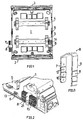
- Fig. 1
- einen erfindungsgemäßen Verteilerkasten in einer Vorderansicht,
- Fig. 2
- eine perspektivische Teilansicht des Verteilerkastens von
Fig. 1 , - Fig. 3
- ein in dem Verteilerkasten von
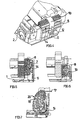
Fig. 1 verwendetes Ösenelement, - Fig. 4
- eine weitere perspektivische Teilansicht des Verteilerkastens von
Fig. 1 , - Fig. 5
- eine Teilschnittansicht des Verteilerkastens von
Fig. 1 , - Fig. 6
- eine der Teilschnittansicht von
Fig. 5 entsprechende Ansicht mit einem verkürzten Ösenelement, und - Fig. 7
- einen Verteilerkasten nach der Erfindung, in dem eine zur Verbindung mit einem Ösenelement vorgesehene Verbindungseinrichtung als Halter für einen Kabelbinder dient.
- Ein Verteilerkasten umfasst einen Boden 1 aus Kunststoff, der einstückig mit einer unteren horizontalen Seitenwand 2 und einer oberen horizontalen Seitenwand 3 verbunden ist. Auf den Kastenboden 1 ist eine nicht gezeigte, im Wesentlichen die vertikalen Seitenwände bildende Deckelhaube aufsetzbar.
- Auf dem Kastenboden sind Hutprofilschienen 4 und 5 für die Aufnahme von Schaltgeräten angebracht. Verschiedene, hier nicht näher beschriebene, teilweise durch Sollbruchstellen herstellbare Öffnungen im Kastenboden 1 und den Seitenwänden 2 und 3 dienen der Befestigung des Kastens an einer Trägerwand sowie der Durchführung von Kabeln.
- An den vertikalen Rändern des Kastenbodens 1 sind jeweils drei flache Stecktaschen 6 gebildet, in welche ein Schenkel 7 eines in
Fig. 3 gesondert dargestellten, etwa U-förmigen Ösenelements 8 einsteckbar ist. - Der Schenkel 7 wie auch ein zweiter Schenkel 9 des Ösenelements 8 weisen Sollbruchstellen 10 auf, durch die Segmente 11 gebildet sind. An jedem der Segmente 11 des Schenkels 7 befindet sich auf einander gegenüberliegenden Seiten jeweils eine Rastnase 12. Die flachen, am Kastenbodenrand angeordneten Stecktaschen 6 weisen jeweils eine die Rastnase 12 aufnehmende Rastöffnung 13 auf (
Fig. 2 ). - Wie aus den
Figuren 4 und 5 hervorgeht, lässt sich mit Hilfe des Ösenelements 8 im Verteilerkasten eine Führung 14 für innerhalb des Verteilerkastens verlaufende Kabel 19 bilden, indem das Ösenelements 8 mit dem Schenkel 7 in einer solchen Drehstellung in eine der Taschen 6 eingesteckt wird, dass der andere Schenkel 9 nach innen weist. - Durch Drehung des Ösenelements 8 um 180° und durch Einstecken des Schenkels 7 in der gedrehten Stellung in eine der Taschen 6 lässt sich eine in den
Fig. 1 und 2 gezeigte, auf der Außenseite des Verteilerkastens verlaufende Kabelführung 15 bilden. Diese Kabelführung 15 lässt sich vorteilhaft während Montagearbeiten an dem Verteilerkasten 1 dafür nutzen, dem Verteilerkasten von oben, insbesondere von der Decke, zugeführte Kabel 21 vorübergehend geordnet am Kasten vorbei zu verlegen, sodass sie den Zugang zum Kasten und damit die Montagearbeiten nicht behindern. - Wie aus
Fig. 6 hervorgeht, lässt sich die Querschnittsfläche des Ösenelements 8 an die Menge der zu führenden Kabel 19 anpassen. Hierzu werden Segmente 11 entfernt und die Schenkel 7 und 9 entsprechend verkürzt. Indem jedes der Segmente 11 auf beiden Seiten eine Rastnase 13 aufweist, rasten auch die verkürzten Schenkel in der Stecktasche 6 ein. - Wie aus
Fig. 7 hervorgeht, weisen die Stecktaschen 6 bei 16 eine Öffnung auf, durch welche hindurch ein Kabelbinderstrang 17 geführt und eine Führungsöse 18 für eine innerhalb des Kastens verlaufende Kabelführung 20 gebildet werden kann.
Claims (10)
- Verteilerkasten mit wenigstens einem Ösenelement (8) zur Bildung einer Führung (14,15) für ein Kabelbündel (19,21) und mit Einrichtungen zur Anbringung des Ösenelements (8) an dem Verteilerkasten unter Bildung einer solchen Kabelführung (15) außerhalb des Verteilerkastens,
dadurch gekennzeichnet,
dass das Ösenelement (8) mit Hilfe der Einrichtungen an einer Vertikalseite des Verteilerkastens anbringbar ist und dass die dadurch außerhalb des Verteilerkastens gebildete Kabelführung (15) eine geordnete Verlegung dem Verteilerkasten von oben zugeführter Kabel an dem Verteilerkasten vorbei und damit frei von Behinderungen des Zugangs zum Verteilerkasten erlaubt. - Verteilerkasten nach Anspruch 1,
dadurch gekennzeichnet,
dass das Ösenelement (8) zur Bildung der Kabelführung (15) außerhalb des Kastens gegenüber einer ersten Position, in der das Ösenelement (8) eine Kabelführung (14) innerhalb des Kastens bildet, um 180° verdreht oder um die Ösenweite versetzt am Verteilerkasten anbringbar ist. - Verteilerkasten nach Anspruch 1 oder 2,
dadurch gekennzeichnet,
dass die Einrichtungen zur Anbringung des Ösenelements (8) an dem Verteilerkasten eine vom Kastenboden (1) oder einer Kastenseitenwand vorstehende Verbindungseinrichtung (6) umfassen. - Vertellerkasten nach Anspruch 3,
dadurch gekennzeichnet,
dass das Ösenelement (8) auf die Verbindungseinrichtung (6) aufsteckbar ist. - Verteilerkasten nach Anspruch 3 oder 4,
dadurch gekennzeichnet,
dass das Ösenelement (8) an der Verbindungseinrichtung (6) einrastet. - Verteilerkasten nach einem der Ansprüche 1 bis 5,
dadurch gekennzeichnet,
dass das Ösenelement (8) teilweise offen mit zwei, jeweils ein freies Ende aufweisenden Schenkeln (7,9) ausgebildet ist. - Verteilerkasten nach Anspruch 6,
dadurch gekennzeichnet,
dass das Ösenelement (8) über wenigstens einen der beiden Schenkel (7,9) an der Verbindungseinrichtung (6) anbringbar ist. - Verteilerkasten nach Anspruch 6 oder 7,
dadurch gekennzeichnet,
dass die Schenkel (7,9) Segmente (11) bildende Sollbruchstellen (10) aufweisen, so dass sich die Schenkellänge segmentweise verringern lässt. - Verteilerkasten nach Anspruch 8,
dadurch gekennzeichnet,
dass an jedem Segment (11) von einem der Schenkel (7) Einrichtungen (12) zur Einrastung des Schenkels (7) an der Verbindungseinrichtung (6) vorgesehen sind. - Verteilerkasten nach einem der Ansprüche 3 bis 9,
dadurch gekennzeichnet,
dass die Verbindungseinrichtung (6) eine Öffnung (16) für die Durchführung eines Kabelbinderstrangs (17) aufweist.
Applications Claiming Priority (1)
| Application Number | Priority Date | Filing Date | Title |
|---|---|---|---|
| DE200810039382 DE102008039382A1 (de) | 2008-08-22 | 2008-08-22 | Verteilerkasten |
Publications (3)
| Publication Number | Publication Date |
|---|---|
| EP2157672A2 EP2157672A2 (de) | 2010-02-24 |
| EP2157672A3 EP2157672A3 (de) | 2012-05-30 |
| EP2157672B1 true EP2157672B1 (de) | 2016-03-23 |
Family
ID=41343199
Family Applications (1)
| Application Number | Title | Priority Date | Filing Date |
|---|---|---|---|
| EP09010493.6A Active EP2157672B1 (de) | 2008-08-22 | 2009-08-14 | Verteilerkasten |
Country Status (5)
| Country | Link |
|---|---|
| EP (1) | EP2157672B1 (de) |
| DE (1) | DE102008039382A1 (de) |
| ES (1) | ES2576007T3 (de) |
| PL (1) | PL2157672T3 (de) |
| PT (1) | PT2157672T (de) |
Family Cites Families (7)
| Publication number | Priority date | Publication date | Assignee | Title |
|---|---|---|---|---|
| DE2816724C2 (de) * | 1978-04-18 | 1982-07-08 | Krone Gmbh, 1000 Berlin | Verbindungs- und Verteilerdose für Fernmeldekabel |
| US4998343A (en) * | 1989-12-12 | 1991-03-12 | Costello Clifford T | Electrical wiring method and apparatus |
| US5073841A (en) * | 1990-02-07 | 1991-12-17 | Amp Incorporated | Wire management system |
| US6327139B1 (en) | 2000-03-21 | 2001-12-04 | International Business Machines Corporation | Electrical equipment rack having cable management arms with flexible linkage |
| AU2002311779A1 (en) * | 2001-03-19 | 2002-10-08 | Lightchip, Inc. | Fiber optic cable restraint |
| DE10325938B4 (de) * | 2003-06-07 | 2016-07-28 | Hager Electro Gmbh | Kleinverteiler |
| DE102005022756A1 (de) * | 2005-05-18 | 2006-11-23 | Hager Electro Gmbh | Halter für einen Kabelkanal |
-
2008
- 2008-08-22 DE DE200810039382 patent/DE102008039382A1/de not_active Withdrawn
-
2009
- 2009-08-14 ES ES09010493.6T patent/ES2576007T3/es active Active
- 2009-08-14 PL PL09010493.6T patent/PL2157672T3/pl unknown
- 2009-08-14 PT PT90104936T patent/PT2157672T/pt unknown
- 2009-08-14 EP EP09010493.6A patent/EP2157672B1/de active Active
Also Published As
| Publication number | Publication date |
|---|---|
| EP2157672A2 (de) | 2010-02-24 |
| DE102008039382A1 (de) | 2010-02-25 |
| PL2157672T3 (pl) | 2016-09-30 |
| PT2157672T (pt) | 2016-07-07 |
| ES2576007T3 (es) | 2016-07-04 |
| EP2157672A3 (de) | 2012-05-30 |
Similar Documents
| Publication | Publication Date | Title |
|---|---|---|
| DE60007228T2 (de) | Kabelhalterung | |
| DE102009005370A1 (de) | Elektrisches Verteilergehäuse für Kraftfahrzeuge | |
| DE102009030798A1 (de) | Schutzvorrichtung für flexible Elemente | |
| WO2013156605A1 (de) | Leitungsführungseinrichtung und modulares bauteilsystem für senkrechte verfahrwege | |
| DE4312779C3 (de) | Leitungshalter für Verdrahtungen in Niederspannungsschaltkreisen elektrischer Geräte | |
| DE102007032186A1 (de) | Trägersystem zur Befestigung von Einrichtungen der Telekommunikations- und Datentechnik | |
| EP2240985B1 (de) | Installationskasten, insbesondere verteilerkasten, zur aufputzinstallation | |
| EP2157672B1 (de) | Verteilerkasten | |
| DE102005004453A1 (de) | Krümmbarer Leitungskanal zur Aufnahme von Leitungen | |
| DE112018007293T5 (de) | Kabelbaumschutzvorrichtung und Kabelbaumverlegestruktur unter Verwendung derselben | |
| DE2820062A1 (de) | Kettenglied und kette | |
| DE10003922C2 (de) | Einbaudose zur Verwendung in einem Kabelkanal, wie Brüstungskanal | |
| WO2008104280A1 (de) | Trägersytem für eine verteileinrichtung für lichtwellenleiter | |
| DE102016124609A1 (de) | Verteilerkasten zum Einbau in eine Wandöffnung | |
| DE2226677C3 (de) | Kabelhalterung | |
| EP2086078B1 (de) | Verteilerkasten zum Einbau in eine Wandöffnung | |
| DE4203066A1 (de) | Kabelkanal, insbesondere verdrahtungskanal | |
| DE202008006111U1 (de) | Anschlussdose für ein Solarmodul | |
| EP0612435B1 (de) | Kabelbaum-legevorrichtung | |
| DE10325938B4 (de) | Kleinverteiler | |
| EP0440972A2 (de) | Kabelkanal, wie Brüstungskanal, Leitungsführungskanal, Geräteeinbaukanal od. dgl. | |
| DE102017116679A1 (de) | Kabelkanal | |
| DE10219794A1 (de) | Anschlussvorrichtung für elektrische Verteiler | |
| WO2008131749A2 (de) | Verteilerkasten | |
| DE102008060361B4 (de) | Anordnung zur Führung elektrischer Leitungen |
Legal Events
| Date | Code | Title | Description |
|---|---|---|---|
| PUAI | Public reference made under article 153(3) epc to a published international application that has entered the european phase |
Free format text: ORIGINAL CODE: 0009012 |
|
| AK | Designated contracting states |
Kind code of ref document: A2 Designated state(s): AT BE BG CH CY CZ DE DK EE ES FI FR GB GR HR HU IE IS IT LI LT LU LV MC MK MT NL NO PL PT RO SE SI SK SM TR |
|
| AX | Request for extension of the european patent |
Extension state: AL BA RS |
|
| PUAL | Search report despatched |
Free format text: ORIGINAL CODE: 0009013 |
|
| RIC1 | Information provided on ipc code assigned before grant |
Ipc: H02B 1/42 20060101AFI20120420BHEP Ipc: H02B 1/20 20060101ALI20120420BHEP |
|
| AK | Designated contracting states |
Kind code of ref document: A3 Designated state(s): AT BE BG CH CY CZ DE DK EE ES FI FR GB GR HR HU IE IS IT LI LT LU LV MC MK MT NL NO PL PT RO SE SI SK SM TR |
|
| AX | Request for extension of the european patent |
Extension state: AL BA RS |
|
| 17P | Request for examination filed |
Effective date: 20121128 |
|
| GRAP | Despatch of communication of intention to grant a patent |
Free format text: ORIGINAL CODE: EPIDOSNIGR1 |
|
| RIC1 | Information provided on ipc code assigned before grant |
Ipc: H02B 1/42 20060101AFI20150826BHEP Ipc: H02B 1/20 20060101ALI20150826BHEP |
|
| INTG | Intention to grant announced |
Effective date: 20150916 |
|
| GRAS | Grant fee paid |
Free format text: ORIGINAL CODE: EPIDOSNIGR3 |
|
| GRAA | (expected) grant |
Free format text: ORIGINAL CODE: 0009210 |
|
| AK | Designated contracting states |
Kind code of ref document: B1 Designated state(s): AT BE BG CH CY CZ DE DK EE ES FI FR GB GR HR HU IE IS IT LI LT LU LV MC MK MT NL NO PL PT RO SE SI SK SM TR |
|
| REG | Reference to a national code |
Ref country code: GB Ref legal event code: FG4D Free format text: NOT ENGLISH |
|
| REG | Reference to a national code |
Ref country code: CH Ref legal event code: EP |
|
| REG | Reference to a national code |
Ref country code: AT Ref legal event code: REF Ref document number: 783986 Country of ref document: AT Kind code of ref document: T Effective date: 20160415 |
|
| REG | Reference to a national code |
Ref country code: IE Ref legal event code: FG4D Free format text: LANGUAGE OF EP DOCUMENT: GERMAN |
|
| REG | Reference to a national code |
Ref country code: DE Ref legal event code: R096 Ref document number: 502009012271 Country of ref document: DE |
|
| REG | Reference to a national code |
Ref country code: CH Ref legal event code: NV Representative=s name: ALDO ROEMPLER PATENTANWALT, CH |
|
| REG | Reference to a national code |
Ref country code: FR Ref legal event code: PLFP Year of fee payment: 8 |
|
| REG | Reference to a national code |
Ref country code: ES Ref legal event code: FG2A Ref document number: 2576007 Country of ref document: ES Kind code of ref document: T3 Effective date: 20160704 |
|
| REG | Reference to a national code |
Ref country code: PT Ref legal event code: SC4A Ref document number: 2157672 Country of ref document: PT Date of ref document: 20160707 Kind code of ref document: T Free format text: AVAILABILITY OF NATIONAL TRANSLATION Effective date: 20160621 |
|
| REG | Reference to a national code |
Ref country code: LT Ref legal event code: MG4D |
|
| REG | Reference to a national code |
Ref country code: NL Ref legal event code: MP Effective date: 20160323 |
|
| PG25 | Lapsed in a contracting state [announced via postgrant information from national office to epo] |
Ref country code: NO Free format text: LAPSE BECAUSE OF FAILURE TO SUBMIT A TRANSLATION OF THE DESCRIPTION OR TO PAY THE FEE WITHIN THE PRESCRIBED TIME-LIMIT Effective date: 20160623 Ref country code: FI Free format text: LAPSE BECAUSE OF FAILURE TO SUBMIT A TRANSLATION OF THE DESCRIPTION OR TO PAY THE FEE WITHIN THE PRESCRIBED TIME-LIMIT Effective date: 20160323 |
|
| PG25 | Lapsed in a contracting state [announced via postgrant information from national office to epo] |
Ref country code: NL Free format text: LAPSE BECAUSE OF FAILURE TO SUBMIT A TRANSLATION OF THE DESCRIPTION OR TO PAY THE FEE WITHIN THE PRESCRIBED TIME-LIMIT Effective date: 20160323 Ref country code: LT Free format text: LAPSE BECAUSE OF FAILURE TO SUBMIT A TRANSLATION OF THE DESCRIPTION OR TO PAY THE FEE WITHIN THE PRESCRIBED TIME-LIMIT Effective date: 20160323 Ref country code: LV Free format text: LAPSE BECAUSE OF FAILURE TO SUBMIT A TRANSLATION OF THE DESCRIPTION OR TO PAY THE FEE WITHIN THE PRESCRIBED TIME-LIMIT Effective date: 20160323 Ref country code: SE Free format text: LAPSE BECAUSE OF FAILURE TO SUBMIT A TRANSLATION OF THE DESCRIPTION OR TO PAY THE FEE WITHIN THE PRESCRIBED TIME-LIMIT Effective date: 20160323 |
|
| REG | Reference to a national code |
Ref country code: GR Ref legal event code: EP Ref document number: 20160401213 Country of ref document: GR Effective date: 20160729 |
|
| PG25 | Lapsed in a contracting state [announced via postgrant information from national office to epo] |
Ref country code: IS Free format text: LAPSE BECAUSE OF FAILURE TO SUBMIT A TRANSLATION OF THE DESCRIPTION OR TO PAY THE FEE WITHIN THE PRESCRIBED TIME-LIMIT Effective date: 20160723 Ref country code: EE Free format text: LAPSE BECAUSE OF FAILURE TO SUBMIT A TRANSLATION OF THE DESCRIPTION OR TO PAY THE FEE WITHIN THE PRESCRIBED TIME-LIMIT Effective date: 20160323 |
|
| PGFP | Annual fee paid to national office [announced via postgrant information from national office to epo] |
Ref country code: IT Payment date: 20160725 Year of fee payment: 8 Ref country code: DE Payment date: 20160826 Year of fee payment: 8 |
|
| PG25 | Lapsed in a contracting state [announced via postgrant information from national office to epo] |
Ref country code: SM Free format text: LAPSE BECAUSE OF FAILURE TO SUBMIT A TRANSLATION OF THE DESCRIPTION OR TO PAY THE FEE WITHIN THE PRESCRIBED TIME-LIMIT Effective date: 20160323 Ref country code: SK Free format text: LAPSE BECAUSE OF FAILURE TO SUBMIT A TRANSLATION OF THE DESCRIPTION OR TO PAY THE FEE WITHIN THE PRESCRIBED TIME-LIMIT Effective date: 20160323 Ref country code: RO Free format text: LAPSE BECAUSE OF FAILURE TO SUBMIT A TRANSLATION OF THE DESCRIPTION OR TO PAY THE FEE WITHIN THE PRESCRIBED TIME-LIMIT Effective date: 20160323 |
|
| PG25 | Lapsed in a contracting state [announced via postgrant information from national office to epo] |
Ref country code: BE Free format text: LAPSE BECAUSE OF NON-PAYMENT OF DUE FEES Effective date: 20160831 |
|
| REG | Reference to a national code |
Ref country code: DE Ref legal event code: R097 Ref document number: 502009012271 Country of ref document: DE |
|
| PLBE | No opposition filed within time limit |
Free format text: ORIGINAL CODE: 0009261 |
|
| STAA | Information on the status of an ep patent application or granted ep patent |
Free format text: STATUS: NO OPPOSITION FILED WITHIN TIME LIMIT |
|
| PG25 | Lapsed in a contracting state [announced via postgrant information from national office to epo] |
Ref country code: DK Free format text: LAPSE BECAUSE OF FAILURE TO SUBMIT A TRANSLATION OF THE DESCRIPTION OR TO PAY THE FEE WITHIN THE PRESCRIBED TIME-LIMIT Effective date: 20160323 |
|
| PG25 | Lapsed in a contracting state [announced via postgrant information from national office to epo] |
Ref country code: BG Free format text: LAPSE BECAUSE OF FAILURE TO SUBMIT A TRANSLATION OF THE DESCRIPTION OR TO PAY THE FEE WITHIN THE PRESCRIBED TIME-LIMIT Effective date: 20160623 |
|
| 26N | No opposition filed |
Effective date: 20170102 |
|
| PG25 | Lapsed in a contracting state [announced via postgrant information from national office to epo] |
Ref country code: MC Free format text: LAPSE BECAUSE OF FAILURE TO SUBMIT A TRANSLATION OF THE DESCRIPTION OR TO PAY THE FEE WITHIN THE PRESCRIBED TIME-LIMIT Effective date: 20160323 |
|
| GBPC | Gb: european patent ceased through non-payment of renewal fee |
Effective date: 20160814 |
|
| PG25 | Lapsed in a contracting state [announced via postgrant information from national office to epo] |
Ref country code: SI Free format text: LAPSE BECAUSE OF FAILURE TO SUBMIT A TRANSLATION OF THE DESCRIPTION OR TO PAY THE FEE WITHIN THE PRESCRIBED TIME-LIMIT Effective date: 20160323 |
|
| REG | Reference to a national code |
Ref country code: IE Ref legal event code: MM4A |
|
| PG25 | Lapsed in a contracting state [announced via postgrant information from national office to epo] |
Ref country code: IE Free format text: LAPSE BECAUSE OF NON-PAYMENT OF DUE FEES Effective date: 20160814 Ref country code: GB Free format text: LAPSE BECAUSE OF NON-PAYMENT OF DUE FEES Effective date: 20160814 |
|
| REG | Reference to a national code |
Ref country code: FR Ref legal event code: PLFP Year of fee payment: 9 |
|
| PG25 | Lapsed in a contracting state [announced via postgrant information from national office to epo] |
Ref country code: LU Free format text: LAPSE BECAUSE OF NON-PAYMENT OF DUE FEES Effective date: 20160814 |
|
| REG | Reference to a national code |
Ref country code: DE Ref legal event code: R119 Ref document number: 502009012271 Country of ref document: DE |
|
| PG25 | Lapsed in a contracting state [announced via postgrant information from national office to epo] |
Ref country code: CY Free format text: LAPSE BECAUSE OF FAILURE TO SUBMIT A TRANSLATION OF THE DESCRIPTION OR TO PAY THE FEE WITHIN THE PRESCRIBED TIME-LIMIT Effective date: 20160323 Ref country code: HU Free format text: LAPSE BECAUSE OF FAILURE TO SUBMIT A TRANSLATION OF THE DESCRIPTION OR TO PAY THE FEE WITHIN THE PRESCRIBED TIME-LIMIT; INVALID AB INITIO Effective date: 20090814 |
|
| PG25 | Lapsed in a contracting state [announced via postgrant information from national office to epo] |
Ref country code: TR Free format text: LAPSE BECAUSE OF FAILURE TO SUBMIT A TRANSLATION OF THE DESCRIPTION OR TO PAY THE FEE WITHIN THE PRESCRIBED TIME-LIMIT Effective date: 20160323 Ref country code: MK Free format text: LAPSE BECAUSE OF FAILURE TO SUBMIT A TRANSLATION OF THE DESCRIPTION OR TO PAY THE FEE WITHIN THE PRESCRIBED TIME-LIMIT Effective date: 20160323 Ref country code: HR Free format text: LAPSE BECAUSE OF FAILURE TO SUBMIT A TRANSLATION OF THE DESCRIPTION OR TO PAY THE FEE WITHIN THE PRESCRIBED TIME-LIMIT Effective date: 20160323 Ref country code: MT Free format text: LAPSE BECAUSE OF FAILURE TO SUBMIT A TRANSLATION OF THE DESCRIPTION OR TO PAY THE FEE WITHIN THE PRESCRIBED TIME-LIMIT Effective date: 20160323 |
|
| PG25 | Lapsed in a contracting state [announced via postgrant information from national office to epo] |
Ref country code: DE Free format text: LAPSE BECAUSE OF NON-PAYMENT OF DUE FEES Effective date: 20180301 |
|
| REG | Reference to a national code |
Ref country code: FR Ref legal event code: PLFP Year of fee payment: 10 |
|
| PG25 | Lapsed in a contracting state [announced via postgrant information from national office to epo] |
Ref country code: IT Free format text: LAPSE BECAUSE OF NON-PAYMENT OF DUE FEES Effective date: 20170814 |
|
| P01 | Opt-out of the competence of the unified patent court (upc) registered |
Effective date: 20230606 |
|
| PGFP | Annual fee paid to national office [announced via postgrant information from national office to epo] |
Ref country code: ES Payment date: 20230901 Year of fee payment: 15 Ref country code: CZ Payment date: 20230721 Year of fee payment: 15 Ref country code: CH Payment date: 20230903 Year of fee payment: 15 Ref country code: AT Payment date: 20230719 Year of fee payment: 15 |
|
| PGFP | Annual fee paid to national office [announced via postgrant information from national office to epo] |
Ref country code: PT Payment date: 20230720 Year of fee payment: 15 Ref country code: PL Payment date: 20230719 Year of fee payment: 15 Ref country code: GR Payment date: 20230829 Year of fee payment: 15 Ref country code: FR Payment date: 20230825 Year of fee payment: 15 |