EP2157007A1 - Two-axle bogie for railway vehicle with radially adjustable wheelsets with cross coupling - Google Patents
Two-axle bogie for railway vehicle with radially adjustable wheelsets with cross coupling Download PDFInfo
- Publication number
- EP2157007A1 EP2157007A1 EP09475002A EP09475002A EP2157007A1 EP 2157007 A1 EP2157007 A1 EP 2157007A1 EP 09475002 A EP09475002 A EP 09475002A EP 09475002 A EP09475002 A EP 09475002A EP 2157007 A1 EP2157007 A1 EP 2157007A1
- Authority
- EP
- European Patent Office
- Prior art keywords
- axle box
- bogie
- axle
- railway vehicle
- dimensional adapter
- Prior art date
- Legal status (The legal status is an assumption and is not a legal conclusion. Google has not performed a legal analysis and makes no representation as to the accuracy of the status listed.)
- Withdrawn
Links
Images




Classifications
-
- B—PERFORMING OPERATIONS; TRANSPORTING
- B61—RAILWAYS
- B61F—RAIL VEHICLE SUSPENSIONS, e.g. UNDERFRAMES, BOGIES OR ARRANGEMENTS OF WHEEL AXLES; RAIL VEHICLES FOR USE ON TRACKS OF DIFFERENT WIDTH; PREVENTING DERAILING OF RAIL VEHICLES; WHEEL GUARDS, OBSTRUCTION REMOVERS OR THE LIKE FOR RAIL VEHICLES
- B61F5/00—Constructional details of bogies; Connections between bogies and vehicle underframes; Arrangements or devices for adjusting or allowing self-adjustment of wheel axles or bogies when rounding curves
- B61F5/38—Arrangements or devices for adjusting or allowing self- adjustment of wheel axles or bogies when rounding curves, e.g. sliding axles, swinging axles
Definitions
- a solution for improvement of guiding characteristics in the curve and stability of two-axle bogie is known; the basis of this solution is diagonal interconnection of the wheels of the two-axle bogie by draw rod - so called cross coupling.
- axle box carrier which becomes an integral part of the axle box by screwing, welding or it is from one piece.
- the L-shaped dimensional adapter is with one arm immovably connected to the axle box carrier, which has for connection with dimensional adapter created one or more mutually related surfaces, whereby each dimensional adapter bypasses wheel from the inner side in order to avoid brake blocks.
- the arms of L-shaped dimensional adapter do not lie in one plane and therefore the L-shaped dimensional adapter contains at least one more bend, through which its connecting points to the axle box carrier and draw rods will get into the required position.
- L-shaped dimensional adapter is manufactured by welding, forging, bending or by casting or by combination of these methods.
- Cross coupling according to this solution lies under the plane created by axis of the bogie wheelsets and bypasses bearing structure of the bogie frame.
- the axle box carrier 2 is an integral part of the axle box 1 .
- the axle box carrier 2 is connected to the axle box 1 by welding. Alternatively, it can be connected by screwing, or the axle box carrier 2 is a part of the axle box 1 made from one piece as a cast.
- Base of the dimensional adapter 3 is firmly connected to the axle box carrier 2 by screwing. Alternatively, connection can be realized through pin or as a cast, and then the axle box 1, as a whole, will contain the axle box carrier 2 , as well as the dimensional adapter 3 .
- the dimensional adapter 3 has to be realized in the variant left and right piece.
- the axle box 1, as one piece, is in the version left and right.
- the dimensional adapter 3 contains an eye 5 on the free arm, to which a draw rod 4 and 7 are connected through a pin.
- the eye 5 of the dimensional adapter 3 lies in the plane that is located under the bearing surface of the spring 6 of the axle box 1 .
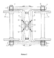
- the draw rod 7 is in the version with rectangular opening and the draw rod 4 without an opening, as can be seen in the picture. Rectangular opening of the draw rod 7 will provide crossing of both draw rods without mutual interference.
- the L-shaped dimensional adapter 3 is connected to the axle box carrier 2 , whereby the shorter arm - base, of the dimensional adapter, which together with its longer free arm comprises L-shape, is created by construction of the eye 5 , to which the draw rod 4 is connected.
- the axle box carrier 2 is an integrated part of the axle box 1 . Connection of the axle box carrier 2 to the axle box 1 is realized by welding. Alternatively, it can be realized through screwing or the axle box carrier 2 is a part of the axle box 1 made from one piece as a cast.
- the arm of the dimensional adapter 3 is firmly connected to the axle box carrier 2 by screwing.
- connection can be realized through pin or as a cast, and then the axle box 1, as a whole, will contain the axle box carrier 2 , as well as the dimensional adapter 3 .
- the L-shaped dimensional adapter 3 has to be realized in the variant left and right piece.
- the axle box 1, as one piece, is in the version left and right.
- the dimensional adapter 3 contains an eye 5 , to which draw rod 4 and 7 are connected through a pin.
- the eye 5 of the dimensional adapter 3 lies in the plane that is located under the bearing surface of the spring 6 of the axle box 1 .
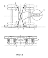
- the draw rod 7 is in the version with rectangular opening and the draw rod 4 without an opening, as can be seen in the picture.
- Rectangular opening of the draw rod 7 will provide crossing of both draw rods without mutual interference.
- rubber-metal pins or bushes can be used instead of ball joints in order to provide necessary freedom of movement in connection with the dimensional adapter 3 , or with the axle box 1 as a whole.
Landscapes
- Engineering & Computer Science (AREA)
- Mechanical Engineering (AREA)
- Handcart (AREA)
- Vehicle Body Suspensions (AREA)
- Pivots And Pivotal Connections (AREA)
Abstract
Description
- Technical solution is related to the railway vehicles.
- For reduction of force effects and wear in the wheel - rail contact, it is preferred, in the field of railway vehicles, loosening of the connection between bogie frame and wheelset (loosening of the wheelset in other) in order to create conditions for radial adjustment of the wheelset during transition through a curve. Except meeting requirements for dynamic conditions, its application into railway vehicles has to meet requirements for simple and trouble-free maintenance, inspection, exchange and adjustability.
- Radial adjustment of the wheelsets during transition through a curve can be reached when using suspension, in the wheelset guidance, which is sufficiently elastic in the longitudinal direction (direction that is parallel with the direction of railway vehicle movement). Forces that are created between wheel and rail during transition through a curve will ensure automatic adjustment of the wheelsets into the position that is very close to the optimal position. This position is characterised by the fact that there occur minimal or no sliding between wheel and rail.
- In the presence, a bogie Y25 Lsod, which belongs among one of standardized bogies of UIC, is known for loose wheelset.
This constructional solution has a tendency to worsen stability of vehicle travel and without additional measures it leads to decrease of speed, during which the stability of the travel occurs. This effect is unwanted and even dangerous, and, therefore, additional measures for securing the stability of the vehicle travel during speed that safely exceed design speed are necessary.
This bogie is not equipped with any device for improvement of the stability (Picture 1). - A solution for improvement of guiding characteristics in the curve and stability of two-axle bogie is known; the basis of this solution is diagonal interconnection of the wheels of the two-axle bogie by draw rod - so called cross coupling.
- For example, these applications of diagonal interconnection of the wheels of two-axle bogie by draw rod are known:
- 1. So called Scheffel bogie (Picture 2), named after its inventor Herbert Scheffel, protected by
USP 4067261 ,WO2000/030914 .
At this type of the bogie, both wheelsets are connected in the way that radial adjustment of preceding wheelset is transferred to the next wheelset. This is gained by mutual interconnection of the wheelsets by cross coupling, which diagonally connects wheels of two-axle bogie by draw rod, by which the effect of automatic guiding and stability of travel is reached. Individual railway vehicle consists of two bogies and superstructure that is fulcrumed on the bogies.
This bogie has usually two auxiliary frames of U shape, marked in the picture as 5 and 6, which are connected to theaxle boxes 7 of the bogie wheelsets. The auxiliary frames are mutually connected through cross coupling 9, which lies basically in the diagonals of the bogie. Cross coupling 9 are connected to the U-shapedauxiliary frames anchor points 10, which lie basically in the plane of thewheelsets axis - 2. Another arrangement contains
USP 6910426 . According to this solution, showed in thepicture 3, the bogie contains two pairs of C-shaped guiding arms, marked in the picture as 5 and 6. two pairs of C-shaped guiding arms are mutually diagonally connected through cross coupling 9. Cross coupling 9 is connected to the guidingarms anchor points 10. - 3. Another known solution for use of diagonal coupling between wheelsets through a cross anchor is that used in the construction of the bogie LEILA. This is an experimental bogie - prototype, which does not have a serial application (Picture 4). In comparison to the other solutions, the axle box is installed from the inner side of wheels.
- The nature of technical solution of two-axle bogie for trailing railway vehicles with radially adjustable wheelsets with cross coupling, which consists of 2 crossed draw rods, which diagonally connects both wheelsets of one bogie, is that ends of the draw rods are equipped with L-shaped dimensional adapters connected to the axle box through axle box carrier, whereby the L-shaped dimensional adapter is realized in the variant left and right and, at the beginning of the free arm, it contains an eye, to which the draw rods are connected through a pin, and which second arm is connected to the axle box carrier by screwing, welding or it is in the variant of one integral part containing the axle box, axle box carrier and L-shaped dimensional adapter. Two crossed draw rods are identical, but one of them contains in the middle a rectangular opening, which dimensions exceed dimensions of the draw rod.
- The nature of technical solution is also the axle box carrier, which becomes an integral part of the axle box by screwing, welding or it is from one piece.
- The nature of the technical solution is also the fact that the L-shaped dimensional adapter is with one arm immovably connected to the axle box carrier, which has for connection with dimensional adapter created one or more mutually related surfaces, whereby each dimensional adapter bypasses wheel from the inner side in order to avoid brake blocks. The arms of L-shaped dimensional adapter do not lie in one plane and therefore the L-shaped dimensional adapter contains at least one more bend, through which its connecting points to the axle box carrier and draw rods will get into the required position.
- L-shaped dimensional adapter is manufactured by welding, forging, bending or by casting or by combination of these methods.
- Cross coupling according to this solution lies under the plane created by axis of the bogie wheelsets and bypasses bearing structure of the bogie frame.
- In the pictures, there are showed known solutions of the bogies with or without cross coupling and solution according to this utility model. In the
Picture 1, there is showed bogie Y25 Lsod, which is one of UIC standardized bogies and it is not equipped with any device for stability improvement. In thePicture 2, there is so called Scheffel bogie with cross coupling, in which the radial positioning of previous wheelset is transfer to the next wheelsets. In thepicture 3, there is depicted another type of cross coupling, bogie LHB, developed for conditions in the Northern Europe. Picture 4 shows diagonal connection between wheelsets in the construction of the bogie LEILA (experimental bogie, prototype). Technical solution according to this utility model in the Y25 bogie is executed in 2 variants showed in thepictures picture 7, there is showed an example of L-shaped dimensional adapter. - Submitted technical solution was applied into the bogie Y25 (Picture 5) L-shaped
dimensional adapter 3, which free arm contains aneye 5, to which a draw rod 4 is connected and second arm is connected to theaxle box carrier 2. Theaxle box carrier 2 is an integral part of theaxle box 1. Theaxle box carrier 2 is connected to theaxle box 1 by welding. Alternatively, it can be connected by screwing, or theaxle box carrier 2 is a part of theaxle box 1 made from one piece as a cast. Base of thedimensional adapter 3 is firmly connected to theaxle box carrier 2 by screwing. Alternatively, connection can be realized through pin or as a cast, and then theaxle box 1, as a whole, will contain theaxle box carrier 2, as well as thedimensional adapter 3. Thedimensional adapter 3 has to be realized in the variant left and right piece. Alternatively, theaxle box 1, as one piece, is in the version left and right. Thedimensional adapter 3, according to this example, contains aneye 5 on the free arm, to which adraw rod 4 and 7 are connected through a pin. Theeye 5 of thedimensional adapter 3 lies in the plane that is located under the bearing surface of thespring 6 of theaxle box 1. Thedraw rod 7 is in the version with rectangular opening and the draw rod 4 without an opening, as can be seen in the picture. Rectangular opening of thedraw rod 7 will provide crossing of both draw rods without mutual interference. At both ends of thedraw rods 4 and 7, there are ball joints that provide swivel type connection with thedimensional adapter 3 or, in another variant, with theaxle box 1 as one whole. Alternatively, rubber-metal pins or bushes can be used instead of ball joints in order to provide necessary freedom of movement in connection with thedimensional adapter 3, or with theaxle box 1 as a whole. - Similarly, as in the example 1, submitted technical solution was applied into the bogie Y25 (Picture 6)
The L-shapeddimensional adapter 3 is connected to theaxle box carrier 2, whereby the shorter arm - base, of the dimensional adapter, which together with its longer free arm comprises L-shape, is created by construction of theeye 5, to which the draw rod 4 is connected. Theaxle box carrier 2 is an integrated part of theaxle box 1. Connection of theaxle box carrier 2 to theaxle box 1 is realized by welding. Alternatively, it can be realized through screwing or theaxle box carrier 2 is a part of theaxle box 1 made from one piece as a cast. The arm of thedimensional adapter 3 is firmly connected to theaxle box carrier 2 by screwing. Alternatively, connection can be realized through pin or as a cast, and then theaxle box 1, as a whole, will contain theaxle box carrier 2, as well as thedimensional adapter 3. The L-shapeddimensional adapter 3 has to be realized in the variant left and right piece. Alternatively, theaxle box 1, as one piece, is in the version left and right. Thedimensional adapter 3 contains aneye 5, to whichdraw rod 4 and 7 are connected through a pin. Theeye 5 of thedimensional adapter 3 lies in the plane that is located under the bearing surface of thespring 6 of theaxle box 1. Thedraw rod 7 is in the version with rectangular opening and the draw rod 4 without an opening, as can be seen in the picture. Rectangular opening of thedraw rod 7 will provide crossing of both draw rods without mutual interference. At both ends of thedraw rods 4 and 7, there are ball joints that provide swivel type connection with thedimensional adapter 3 or, in another variant, with theaxle box 1 as one whole. Alternatively, rubber-metal pins or bushes can be used instead of ball joints in order to provide necessary freedom of movement in connection with thedimensional adapter 3, or with theaxle box 1 as a whole. -
- 1. axle box
- 2. axle box carrier
- 3. L-shaped dimensional adapter
- 4. draw rod
- 5. eye
- 6. spring
- 7. draw rod with rectangular opening
Claims (7)
- Two-axle bogie for trailing railway vehicle with radially adjustable wheelsets with cross coupling, which consists of 2 crossed draw rods, which diagonally connects both wheelsets of one bogie, comprising crossed draw rods (4) and (7), which ends are provided with L-shaped dimensional adapters (3) connected with axle box (1) through axle box carrier (2).
- Two-axle bogie for trailing railway vehicle as claimed in claim 1, wherein L-shaped dimensional adapter (3) is in the variant left and right and it contains an eye (5), at the end of the free arm, into which a draw rod (4) and/or (7) is connected through a pin, and which second arm is connected to the axle box carrier (2) by screwing, welding, or it is in the version of one integral part, containing axle box (1), axle box carrier (2) and dimensional adapter (3).
- Two-axle bogie for trailing railway vehicle as claimed in claims 1 and 2, wherein 2 crossed draw rods (4) and (7) are identical, but draw rod (7) contains in the middle a rectangular opening (8), which dimensions exceed dimensions of the draw rod.
- Two-axle bogie for trailing railway vehicle as claimed in claims 1 up to 3, wherein the axle box carrier (2) is an integral part of the axle box (1) by welding, screwing or from one piece.
- Two-axle bogie for trailing railway vehicle as claimed in claim 1, wherein the L-shaped dimensional adapter (3) is with one arm immovably connected to the axle box carrier (2), which has for connection with dimensional adapter (3) created one or more mutually related surfaces, whereby each dimensional adapter (3) bypasses wheel from the inner side in order to avoid brake blocks.
- Two-axle bogie for trailing railway vehicle as claimed in claim 5, wherein the arms of L-shaped dimensional adapter (3) do not lie in one plane and therefore the L-shaped dimensional adapter (3) contains at least one more bend, through which its connecting points to the axle box carrier (2) and draw rod (4) and/or (7) will get into the required position.
- Two-axle bogie for trailing railway vehicle as claimed in claim 1, wherein the L-shaped dimensional adapter (3) is manufactured by welding, forging, bending or casting or by combination of these methods.
Applications Claiming Priority (1)
| Application Number | Priority Date | Filing Date | Title |
|---|---|---|---|
| SK50042-2008U SK5196Y1 (en) | 2008-08-21 | 2008-08-21 | Two-axle bogies for rail vehicle with radial settings coupled wheels by cross member |
Publications (1)
| Publication Number | Publication Date |
|---|---|
| EP2157007A1 true EP2157007A1 (en) | 2010-02-24 |
Family
ID=41328607
Family Applications (1)
| Application Number | Title | Priority Date | Filing Date |
|---|---|---|---|
| EP09475002A Withdrawn EP2157007A1 (en) | 2008-08-21 | 2009-05-11 | Two-axle bogie for railway vehicle with radially adjustable wheelsets with cross coupling |
Country Status (4)
| Country | Link |
|---|---|
| EP (1) | EP2157007A1 (en) |
| CN (1) | CN101654111A (en) |
| RU (1) | RU91956U1 (en) |
| SK (1) | SK5196Y1 (en) |
Cited By (4)
| Publication number | Priority date | Publication date | Assignee | Title |
|---|---|---|---|---|
| CN102601594A (en) * | 2012-04-01 | 2012-07-25 | 株洲春华实业有限责任公司 | Forge forming process for shaking seat of bogie and shaking seat in forge forming |
| CN102874266A (en) * | 2012-10-22 | 2013-01-16 | 齐齐哈尔轨道交通装备有限责任公司 | Bogie and truck applying same |
| CN109107169A (en) * | 2018-09-19 | 2019-01-01 | 深圳市鑫美幻想工程有限公司 | A kind of guiding device for motor-trolley for amusement |
| CN115027520A (en) * | 2022-05-31 | 2022-09-09 | 中车株洲电力机车有限公司 | Self-steering radial bogie of railway vehicle and railway vehicle |
Families Citing this family (4)
| Publication number | Priority date | Publication date | Assignee | Title |
|---|---|---|---|---|
| RU2563711C2 (en) * | 2013-07-22 | 2015-09-20 | Цзинань Рейлуэй Виклз Иквипмент Ко., Лтд. | Radial welded truck |
| CN103332203B (en) * | 2013-07-22 | 2016-06-29 | 济南轨道交通装备有限责任公司 | Big axle weight low dynamics radially welding bogie |
| DE102014208934B4 (en) * | 2014-05-12 | 2015-11-26 | Siemens Aktiengesellschaft | Storage structure for storage of wind turbine components |
| US20180257681A1 (en) * | 2017-03-09 | 2018-09-13 | Amsted Rail Company, Inc. | Passive steering for a three piece railway truck |
Citations (18)
| Publication number | Priority date | Publication date | Assignee | Title |
|---|---|---|---|---|
| US135614A (en) * | 1873-02-04 | Improvement in railroad-car trucks | ||
| US986315A (en) * | 1909-05-06 | 1911-03-07 | Charles H Ruggles | Log and lumber car. |
| DE837711C (en) * | 1949-02-10 | 1952-05-02 | Roman Liechty Dipl Ing | Axle control device for the wheel axles of rail vehicles with a three-armed adjusting lever |
| DE2514361A1 (en) * | 1974-04-05 | 1975-10-16 | South African Inventions | Railway vehicle suspension - wheelset bearings are cross connected diagonally by pairs of ties |
| US4067261A (en) | 1972-11-10 | 1978-01-10 | South African Inventions Development Corporation | Damping railway vehicle suspension |
| GB1573324A (en) * | 1976-09-27 | 1980-08-20 | Gen Steel Ind Inc | Radial axle railway bogie |
| US4237791A (en) * | 1978-08-24 | 1980-12-09 | General Steel Industries, Inc. | Radial axle railway truck disc brakes |
| US4258629A (en) * | 1979-09-04 | 1981-03-31 | General Steel Industries, Inc. | Braking and steering radial truck |
| FR2508403A1 (en) * | 1981-06-26 | 1982-12-31 | Lucas Ind Plc | STEERING VEHICLE STEERING BOGGIE, EQUIPPED WITH A DISC BRAKE |
| US4429637A (en) * | 1981-10-19 | 1984-02-07 | Lukens General Industries, Inc. | Railway vehicle truck |
| EP0161729A1 (en) * | 1984-05-14 | 1985-11-21 | RMO-Werkspoor Services B.V. | Bogie for a rail vehicle |
| JPS61241259A (en) * | 1985-04-17 | 1986-10-27 | 株式会社東芝 | Steering truck |
| EP0387744A2 (en) * | 1989-03-15 | 1990-09-19 | Gec Alsthom Sa | Railway bogie comprising a frame and two steerable axles |
| DE4034221A1 (en) * | 1989-11-01 | 1991-05-02 | Rautaruukki Oy | RAIL VEHICLE BOG |
| US5243920A (en) * | 1991-07-22 | 1993-09-14 | Utdc Inc. | Brace connection for frame braced truck |
| US5555816A (en) * | 1995-03-06 | 1996-09-17 | M-K Rail Corporation | Self steering railway truck |
| WO2000030914A1 (en) | 1998-11-26 | 2000-06-02 | Herbert Scheffel | Cross-anchor railway bogie |
| US6910426B2 (en) | 2003-01-31 | 2005-06-28 | Besco Limited | Control arm system for steering bogie wheels and axles |
-
2008
- 2008-08-21 SK SK50042-2008U patent/SK5196Y1/en unknown
-
2009
- 2009-04-27 RU RU2009115797/22U patent/RU91956U1/en active
- 2009-04-28 CN CN200910135380A patent/CN101654111A/en active Pending
- 2009-05-11 EP EP09475002A patent/EP2157007A1/en not_active Withdrawn
Patent Citations (18)
| Publication number | Priority date | Publication date | Assignee | Title |
|---|---|---|---|---|
| US135614A (en) * | 1873-02-04 | Improvement in railroad-car trucks | ||
| US986315A (en) * | 1909-05-06 | 1911-03-07 | Charles H Ruggles | Log and lumber car. |
| DE837711C (en) * | 1949-02-10 | 1952-05-02 | Roman Liechty Dipl Ing | Axle control device for the wheel axles of rail vehicles with a three-armed adjusting lever |
| US4067261A (en) | 1972-11-10 | 1978-01-10 | South African Inventions Development Corporation | Damping railway vehicle suspension |
| DE2514361A1 (en) * | 1974-04-05 | 1975-10-16 | South African Inventions | Railway vehicle suspension - wheelset bearings are cross connected diagonally by pairs of ties |
| GB1573324A (en) * | 1976-09-27 | 1980-08-20 | Gen Steel Ind Inc | Radial axle railway bogie |
| US4237791A (en) * | 1978-08-24 | 1980-12-09 | General Steel Industries, Inc. | Radial axle railway truck disc brakes |
| US4258629A (en) * | 1979-09-04 | 1981-03-31 | General Steel Industries, Inc. | Braking and steering radial truck |
| FR2508403A1 (en) * | 1981-06-26 | 1982-12-31 | Lucas Ind Plc | STEERING VEHICLE STEERING BOGGIE, EQUIPPED WITH A DISC BRAKE |
| US4429637A (en) * | 1981-10-19 | 1984-02-07 | Lukens General Industries, Inc. | Railway vehicle truck |
| EP0161729A1 (en) * | 1984-05-14 | 1985-11-21 | RMO-Werkspoor Services B.V. | Bogie for a rail vehicle |
| JPS61241259A (en) * | 1985-04-17 | 1986-10-27 | 株式会社東芝 | Steering truck |
| EP0387744A2 (en) * | 1989-03-15 | 1990-09-19 | Gec Alsthom Sa | Railway bogie comprising a frame and two steerable axles |
| DE4034221A1 (en) * | 1989-11-01 | 1991-05-02 | Rautaruukki Oy | RAIL VEHICLE BOG |
| US5243920A (en) * | 1991-07-22 | 1993-09-14 | Utdc Inc. | Brace connection for frame braced truck |
| US5555816A (en) * | 1995-03-06 | 1996-09-17 | M-K Rail Corporation | Self steering railway truck |
| WO2000030914A1 (en) | 1998-11-26 | 2000-06-02 | Herbert Scheffel | Cross-anchor railway bogie |
| US6910426B2 (en) | 2003-01-31 | 2005-06-28 | Besco Limited | Control arm system for steering bogie wheels and axles |
Cited By (7)
| Publication number | Priority date | Publication date | Assignee | Title |
|---|---|---|---|---|
| CN102601594A (en) * | 2012-04-01 | 2012-07-25 | 株洲春华实业有限责任公司 | Forge forming process for shaking seat of bogie and shaking seat in forge forming |
| CN102874266A (en) * | 2012-10-22 | 2013-01-16 | 齐齐哈尔轨道交通装备有限责任公司 | Bogie and truck applying same |
| CN102874266B (en) * | 2012-10-22 | 2015-08-12 | 齐齐哈尔轨道交通装备有限责任公司 | A kind of bogie truck and apply the lorry of this bogie truck |
| CN109107169A (en) * | 2018-09-19 | 2019-01-01 | 深圳市鑫美幻想工程有限公司 | A kind of guiding device for motor-trolley for amusement |
| CN109107169B (en) * | 2018-09-19 | 2024-05-28 | 深圳市鑫美幻想工程有限公司 | Guiding device for recreation railcar |
| CN115027520A (en) * | 2022-05-31 | 2022-09-09 | 中车株洲电力机车有限公司 | Self-steering radial bogie of railway vehicle and railway vehicle |
| CN115027520B (en) * | 2022-05-31 | 2023-05-02 | 中车株洲电力机车有限公司 | Self-guiding radial bogie of railway vehicle and railway vehicle |
Also Published As
| Publication number | Publication date |
|---|---|
| SK500422008U1 (en) | 2009-01-07 |
| CN101654111A (en) | 2010-02-24 |
| SK5196Y1 (en) | 2009-06-05 |
| RU91956U1 (en) | 2010-03-10 |
Similar Documents
| Publication | Publication Date | Title |
|---|---|---|
| EP2157007A1 (en) | Two-axle bogie for railway vehicle with radially adjustable wheelsets with cross coupling | |
| CN110143213A (en) | A bogie traction device and its application | |
| CN101934740A (en) | Levitation frame device for high-speed magnetic levitation train | |
| CN109515465A (en) | A kind of built-in bogie of high-speed railway lorry axle box | |
| JP6943586B2 (en) | Bogie trolley with external motor and railroad vehicle linked to it | |
| CN206664601U (en) | A kind of foldable hitch for rolling stock | |
| CN202987177U (en) | Railway freight car and spherical center plate anti-separating system thereof | |
| WO2022205914A1 (en) | Axle box suspension device, bogie, and railway wagon | |
| CN207157227U (en) | A kind of brake clamp mounting seat applied to gauge-changeable bogie | |
| WO2022205913A1 (en) | Axle box suspension device and bogie | |
| CN210822266U (en) | Single-shaft bogie, vehicle and motor train unit suitable for high-speed operation | |
| CN112406928A (en) | A three-axle bogie | |
| CN203332134U (en) | Large-axle-load low-power radial welding type bogie | |
| CN105460041A (en) | Forced guide mechanism for bogie | |
| CN101659264B (en) | Plate-spring straddle-type four-shaft steering rack used for railway crane | |
| CN207157228U (en) | A kind of brake apparatus applied to gauge-changeable bogie | |
| CN101804819A (en) | Bogie truck radial mechanism of locomotive | |
| CN207360336U (en) | A kind of brake clamp locating piece applied to gauge-changeable bogie | |
| CN115782948A (en) | A railway freight car bogie with built-in quasi-gauge axle box | |
| CN104401344B (en) | Rail locomotive and radial steering | |
| CN207360335U (en) | A kind of braking flap seat applied to gauge-changeable bogie | |
| CN209142148U (en) | Uncontrollable machinery inner bearing type parking anti-running device | |
| CN207875661U (en) | A kind of high-speed EMUs axle box device for the conversion of quasi- arrow gauge | |
| CZ305621B6 (en) | Rail vehicle bogie | |
| RU175567U1 (en) | Coupling head of clearance-free coupling device |
Legal Events
| Date | Code | Title | Description |
|---|---|---|---|
| PUAI | Public reference made under article 153(3) epc to a published international application that has entered the european phase |
Free format text: ORIGINAL CODE: 0009012 |
|
| AK | Designated contracting states |
Kind code of ref document: A1 Designated state(s): AT BE BG CH CY CZ DE DK EE ES FI FR GB GR HR HU IE IS IT LI LT LU LV MC MK MT NL NO PL PT RO SE SI SK TR |
|
| AX | Request for extension of the european patent |
Extension state: RS |
|
| 17P | Request for examination filed |
Effective date: 20100820 |
|
| 17Q | First examination report despatched |
Effective date: 20110304 |
|
| STAA | Information on the status of an ep patent application or granted ep patent |
Free format text: STATUS: EXAMINATION IS IN PROGRESS |
|
| STAA | Information on the status of an ep patent application or granted ep patent |
Free format text: STATUS: THE APPLICATION IS DEEMED TO BE WITHDRAWN |
|
| 18D | Application deemed to be withdrawn |
Effective date: 20161201 |