EP2156025B2 - Harnstofftank und grundplatte mit integriertem erwärmungselement - Google Patents
Harnstofftank und grundplatte mit integriertem erwärmungselement Download PDFInfo
- Publication number
- EP2156025B2 EP2156025B2 EP08759611.0A EP08759611A EP2156025B2 EP 2156025 B2 EP2156025 B2 EP 2156025B2 EP 08759611 A EP08759611 A EP 08759611A EP 2156025 B2 EP2156025 B2 EP 2156025B2
- Authority
- EP
- European Patent Office
- Prior art keywords
- tank
- flexible
- heater
- urea
- tank according
- Prior art date
- Legal status (The legal status is an assumption and is not a legal conclusion. Google has not performed a legal analysis and makes no representation as to the accuracy of the status listed.)
- Active
Links
Images
Classifications
-
- F—MECHANICAL ENGINEERING; LIGHTING; HEATING; WEAPONS; BLASTING
- F24—HEATING; RANGES; VENTILATING
- F24H—FLUID HEATERS, e.g. WATER OR AIR HEATERS, HAVING HEAT-GENERATING MEANS, e.g. HEAT PUMPS, IN GENERAL
- F24H1/00—Water heaters, e.g. boilers, continuous-flow heaters or water-storage heaters
- F24H1/18—Water-storage heaters
- F24H1/20—Water-storage heaters with immersed heating elements, e.g. electric elements or furnace tubes
- F24H1/201—Water-storage heaters with immersed heating elements, e.g. electric elements or furnace tubes using electric energy supply
- F24H1/202—Water-storage heaters with immersed heating elements, e.g. electric elements or furnace tubes using electric energy supply with resistances
-
- B—PERFORMING OPERATIONS; TRANSPORTING
- B60—VEHICLES IN GENERAL
- B60K—ARRANGEMENT OR MOUNTING OF PROPULSION UNITS OR OF TRANSMISSIONS IN VEHICLES; ARRANGEMENT OR MOUNTING OF PLURAL DIVERSE PRIME-MOVERS IN VEHICLES; AUXILIARY DRIVES FOR VEHICLES; INSTRUMENTATION OR DASHBOARDS FOR VEHICLES; ARRANGEMENTS IN CONNECTION WITH COOLING, AIR INTAKE, GAS EXHAUST OR FUEL SUPPLY OF PROPULSION UNITS IN VEHICLES
- B60K13/00—Arrangement in connection with combustion air intake or gas exhaust of propulsion units
- B60K13/04—Arrangement in connection with combustion air intake or gas exhaust of propulsion units concerning exhaust
-
- F—MECHANICAL ENGINEERING; LIGHTING; HEATING; WEAPONS; BLASTING
- F01—MACHINES OR ENGINES IN GENERAL; ENGINE PLANTS IN GENERAL; STEAM ENGINES
- F01N—GAS-FLOW SILENCERS OR EXHAUST APPARATUS FOR MACHINES OR ENGINES IN GENERAL; GAS-FLOW SILENCERS OR EXHAUST APPARATUS FOR INTERNAL-COMBUSTION ENGINES
- F01N3/00—Exhaust or silencing apparatus having means for purifying, rendering innocuous, or otherwise treating exhaust
- F01N3/08—Exhaust or silencing apparatus having means for purifying, rendering innocuous, or otherwise treating exhaust for rendering innocuous
- F01N3/10—Exhaust or silencing apparatus having means for purifying, rendering innocuous, or otherwise treating exhaust for rendering innocuous by thermal or catalytic conversion of noxious components of exhaust
- F01N3/18—Exhaust or silencing apparatus having means for purifying, rendering innocuous, or otherwise treating exhaust for rendering innocuous by thermal or catalytic conversion of noxious components of exhaust characterised by methods of operation; Control
- F01N3/20—Exhaust or silencing apparatus having means for purifying, rendering innocuous, or otherwise treating exhaust for rendering innocuous by thermal or catalytic conversion of noxious components of exhaust characterised by methods of operation; Control specially adapted for catalytic conversion
- F01N3/206—Adding periodically or continuously substances to exhaust gases for promoting purification, e.g. catalytic material in liquid form, NOx reducing agents
- F01N3/2066—Selective catalytic reduction [SCR]
-
- F—MECHANICAL ENGINEERING; LIGHTING; HEATING; WEAPONS; BLASTING
- F01—MACHINES OR ENGINES IN GENERAL; ENGINE PLANTS IN GENERAL; STEAM ENGINES
- F01N—GAS-FLOW SILENCERS OR EXHAUST APPARATUS FOR MACHINES OR ENGINES IN GENERAL; GAS-FLOW SILENCERS OR EXHAUST APPARATUS FOR INTERNAL-COMBUSTION ENGINES
- F01N3/00—Exhaust or silencing apparatus having means for purifying, rendering innocuous, or otherwise treating exhaust
- F01N3/08—Exhaust or silencing apparatus having means for purifying, rendering innocuous, or otherwise treating exhaust for rendering innocuous
- F01N3/10—Exhaust or silencing apparatus having means for purifying, rendering innocuous, or otherwise treating exhaust for rendering innocuous by thermal or catalytic conversion of noxious components of exhaust
- F01N3/24—Exhaust or silencing apparatus having means for purifying, rendering innocuous, or otherwise treating exhaust for rendering innocuous by thermal or catalytic conversion of noxious components of exhaust characterised by constructional aspects of converting apparatus
- F01N3/28—Construction of catalytic reactors
- F01N3/2896—Liquid catalyst carrier
-
- F—MECHANICAL ENGINEERING; LIGHTING; HEATING; WEAPONS; BLASTING
- F24—HEATING; RANGES; VENTILATING
- F24H—FLUID HEATERS, e.g. WATER OR AIR HEATERS, HAVING HEAT-GENERATING MEANS, e.g. HEAT PUMPS, IN GENERAL
- F24H1/00—Water heaters, e.g. boilers, continuous-flow heaters or water-storage heaters
- F24H1/18—Water-storage heaters
- F24H1/185—Water-storage heaters using electric energy supply
-
- H—ELECTRICITY
- H05—ELECTRIC TECHNIQUES NOT OTHERWISE PROVIDED FOR
- H05B—ELECTRIC HEATING; ELECTRIC LIGHT SOURCES NOT OTHERWISE PROVIDED FOR; CIRCUIT ARRANGEMENTS FOR ELECTRIC LIGHT SOURCES, IN GENERAL
- H05B3/00—Ohmic-resistance heating
- H05B3/0014—Devices wherein the heating current flows through particular resistances
-
- H—ELECTRICITY
- H05—ELECTRIC TECHNIQUES NOT OTHERWISE PROVIDED FOR
- H05B—ELECTRIC HEATING; ELECTRIC LIGHT SOURCES NOT OTHERWISE PROVIDED FOR; CIRCUIT ARRANGEMENTS FOR ELECTRIC LIGHT SOURCES, IN GENERAL
- H05B3/00—Ohmic-resistance heating
- H05B3/78—Heating arrangements specially adapted for immersion heating
-
- B—PERFORMING OPERATIONS; TRANSPORTING
- B60—VEHICLES IN GENERAL
- B60K—ARRANGEMENT OR MOUNTING OF PROPULSION UNITS OR OF TRANSMISSIONS IN VEHICLES; ARRANGEMENT OR MOUNTING OF PLURAL DIVERSE PRIME-MOVERS IN VEHICLES; AUXILIARY DRIVES FOR VEHICLES; INSTRUMENTATION OR DASHBOARDS FOR VEHICLES; ARRANGEMENTS IN CONNECTION WITH COOLING, AIR INTAKE, GAS EXHAUST OR FUEL SUPPLY OF PROPULSION UNITS IN VEHICLES
- B60K15/00—Arrangement in connection with fuel supply of combustion engines or other fuel consuming energy converters, e.g. fuel cells; Mounting or construction of fuel tanks
- B60K15/03—Fuel tanks
- B60K2015/03328—Arrangements or special measures related to fuel tanks or fuel handling
- B60K2015/03427—Arrangements or special measures related to fuel tanks or fuel handling for heating fuel, e.g. to avoiding freezing
-
- F—MECHANICAL ENGINEERING; LIGHTING; HEATING; WEAPONS; BLASTING
- F01—MACHINES OR ENGINES IN GENERAL; ENGINE PLANTS IN GENERAL; STEAM ENGINES
- F01N—GAS-FLOW SILENCERS OR EXHAUST APPARATUS FOR MACHINES OR ENGINES IN GENERAL; GAS-FLOW SILENCERS OR EXHAUST APPARATUS FOR INTERNAL-COMBUSTION ENGINES
- F01N2610/00—Adding substances to exhaust gases
- F01N2610/02—Adding substances to exhaust gases the substance being ammonia or urea
-
- F—MECHANICAL ENGINEERING; LIGHTING; HEATING; WEAPONS; BLASTING
- F01—MACHINES OR ENGINES IN GENERAL; ENGINE PLANTS IN GENERAL; STEAM ENGINES
- F01N—GAS-FLOW SILENCERS OR EXHAUST APPARATUS FOR MACHINES OR ENGINES IN GENERAL; GAS-FLOW SILENCERS OR EXHAUST APPARATUS FOR INTERNAL-COMBUSTION ENGINES
- F01N2610/00—Adding substances to exhaust gases
- F01N2610/10—Adding substances to exhaust gases the substance being heated, e.g. by heating tank or supply line of the added substance
-
- F—MECHANICAL ENGINEERING; LIGHTING; HEATING; WEAPONS; BLASTING
- F01—MACHINES OR ENGINES IN GENERAL; ENGINE PLANTS IN GENERAL; STEAM ENGINES
- F01N—GAS-FLOW SILENCERS OR EXHAUST APPARATUS FOR MACHINES OR ENGINES IN GENERAL; GAS-FLOW SILENCERS OR EXHAUST APPARATUS FOR INTERNAL-COMBUSTION ENGINES
- F01N2610/00—Adding substances to exhaust gases
- F01N2610/14—Arrangements for the supply of substances, e.g. conduits
- F01N2610/1406—Storage means for substances, e.g. tanks or reservoirs
-
- F—MECHANICAL ENGINEERING; LIGHTING; HEATING; WEAPONS; BLASTING
- F01—MACHINES OR ENGINES IN GENERAL; ENGINE PLANTS IN GENERAL; STEAM ENGINES
- F01N—GAS-FLOW SILENCERS OR EXHAUST APPARATUS FOR MACHINES OR ENGINES IN GENERAL; GAS-FLOW SILENCERS OR EXHAUST APPARATUS FOR INTERNAL-COMBUSTION ENGINES
- F01N2610/00—Adding substances to exhaust gases
- F01N2610/14—Arrangements for the supply of substances, e.g. conduits
- F01N2610/1426—Filtration means
-
- Y—GENERAL TAGGING OF NEW TECHNOLOGICAL DEVELOPMENTS; GENERAL TAGGING OF CROSS-SECTIONAL TECHNOLOGIES SPANNING OVER SEVERAL SECTIONS OF THE IPC; TECHNICAL SUBJECTS COVERED BY FORMER USPC CROSS-REFERENCE ART COLLECTIONS [XRACs] AND DIGESTS
- Y02—TECHNOLOGIES OR APPLICATIONS FOR MITIGATION OR ADAPTATION AGAINST CLIMATE CHANGE
- Y02A—TECHNOLOGIES FOR ADAPTATION TO CLIMATE CHANGE
- Y02A50/00—TECHNOLOGIES FOR ADAPTATION TO CLIMATE CHANGE in human health protection, e.g. against extreme weather
- Y02A50/20—Air quality improvement or preservation, e.g. vehicle emission control or emission reduction by using catalytic converters
-
- Y—GENERAL TAGGING OF NEW TECHNOLOGICAL DEVELOPMENTS; GENERAL TAGGING OF CROSS-SECTIONAL TECHNOLOGIES SPANNING OVER SEVERAL SECTIONS OF THE IPC; TECHNICAL SUBJECTS COVERED BY FORMER USPC CROSS-REFERENCE ART COLLECTIONS [XRACs] AND DIGESTS
- Y02—TECHNOLOGIES OR APPLICATIONS FOR MITIGATION OR ADAPTATION AGAINST CLIMATE CHANGE
- Y02T—CLIMATE CHANGE MITIGATION TECHNOLOGIES RELATED TO TRANSPORTATION
- Y02T10/00—Road transport of goods or passengers
- Y02T10/10—Internal combustion engine [ICE] based vehicles
- Y02T10/12—Improving ICE efficiencies
Definitions
- the present application relates to a urea tank with an integrated heating element, and also to a base plate intended for such a tank and that integrates the heating element.
- One known way to achieve this objective is to use the SCR (Selective Catalytic Reduction) process which enables the reduction of nitrogen oxides by injection of a reducing agent, generally ammonia, into the exhaust line.
- This ammonia may derive from the pyrolytic decomposition of an ammonia precursor solution, whose concentration may be the eutectic concentration.
- Such an ammonia precursor is generally a urea solution.
- Application FR 06/07531 in the name of the Applicant aims to solve this specific problem by providing a hollow connection equipped, since its manufacture, with an integrated heating filament, at least one part of which extends freely inside the passage provided for the liquid. Such an arrangement makes it possible to ensure that the liquid is in direct contact with a large heating surface area, and therefore to heat it rapidly.
- Application EP 1 582 732 A discloses an urea tank with an integrated heating element.
- the present invention especially aims to solve this problem by providing a liquid tank equipped internally with a particular heater, the flexibility, shape and heating power of which may easily be adapted to any geometry of the tank or of its accessories.
- the present application relates to a urea tank with an integrated heating element in which said heating element comprises at least one flexible heating part (that is to say, equipped with a device enabling it to heat up, such as a resistive element for example).
- This flexible part is a flexible heater, that is to say that it comprises at least one resistive track inserted between two flexible films or affixed to a flexible film (for example, see Patent US 7,268,325 which describes such heaters and their methods of manufacture).
- the heating element is predominantly composed of a flexible heater.
- urea is understood to mean any, generally aqueous, solution containing urea.
- the invention gives good results with eutectic water/urea solutions for which there is a standard quality: for example, according to the standard DIN 70070, in the case of the AdBlue ® solution (commercial solution of urea), the urea content is between 31.8% and 33.2% (by weight) (i.e. 32.5 +/-0.7 wt%) hence an available amount of ammonia between 18.0% and 18.8%.
- the invention may also be applied to the urea/ammonium formate mixtures, also in aqueous solution, sold under the trade name Denoxium TM and of which one of the compositions (Denoxium-30) contains an equivalent amount of ammonia to that of the Adblue ® solution.
- Denoxium TM aqueous solution
- the latter have the advantage of only freezing from -30°C onwards (as opposed to -11°C), but have the disadvantages of corrosion problems linked to the possible release of formic acid.
- the present invention is particularly advantageous in the context of eutectic water/urea solutions.
- the urea tank according to the invention may be made from any material, preferably one that is chemically resistant to urea. In general, this is metal or plastic. Polyolefins, in particular polyethylene (and more particularly HDPE or high-density polyethylene), constitute preferred materials.
- This tank may be produced by any conversion processes known in the case of hollow bodies.
- One preferred processing method in particular when the tank is made of plastic, and in particular HDPE, is the extrusion-blow moulding process.
- a parison in one or more parts is obtained by extrusion, and is then shaped by blow moulding in a mould.
- One-part moulding of the tank from a single parison gives good results.
- This tank is advantageously equipped with a base plate or mounting plate (that is to say a support having substantially the shape of a plate) onto which at least one active accessory of the urea storage system and/or injection system is attached.
- This base plate generally has a perimeter, closed up on itself, of any shape. Usually, its perimeter has a circular shape.
- This base plate therefore incorporates at least one component that is active during storage and/or injection. This is understood to mean that the component is attached to or produced as one part with the base plate. This component may be incorporated inside the tank, or on the outside with, if necessary, a connection (delivery tube) passing through it.
- the base plate according to this variant of the invention integrates several active storage and/or metering components and, more particularly preferably, it integrates all the active components which are brought to be in contact with the liquid additive found in, leaving from or arriving into the additive tank.
- the component is chosen from the following elements: a pump; a level gauge; a temperature sensor; a quality sensor; a pressure sensor and a pressure regulator.
- a pump a pump
- a level gauge a temperature sensor
- a quality sensor a sensor
- a pressure sensor a pressure regulator
- the level gauge may be of any type. Preferably, it is a gauge with no moving parts, for example of the capacitive type.
- the base plate is based on a material that is resistant to urea and to the products created during ageing of the latter, such as polyacetal, and in particular POM (polyoxymethylene); polyphthalamides (for example, AMODEL ® grades); or polyamides, and in particular grades of polyamides that are reinforced (for example with glass fibres).
- the base plate is made of polyamide and it comprises a delivery tube moulded as one piece with it as described previously.
- the heater may be advantageous to locally control its specific power, that is to say to locally vary the power loss per unit area of resistive track by altering the length and width of the resistive track. For example, if the width and length of a resistive track applied to a given surface are doubled, its total resistance and the power dissipated by this track will remain unchanged. On the other hand, the total surface area of the track will be multiplied by 4, leading to a specific power (or power loss per unit area of track) divided by 4. This therefore results in a lower track temperature at this location.
- body is understood to mean a part of the heater where the tentacles start from or where the resistive tracks start from and arrive at.
- the abovementioned tentacles may be obtained in any known manner.
- they are the product of cuts made in the heater itself without interrupting the resistive track or tracks.
- One particular way of proceeding consists in placing the resistive tracks onto a silicone film according to a preestablished pattern; in covering the tracks with a second silicone film; and finally in carrying out the aforementioned cuts.
- the flexible heater is located inside the urea tank, and is therefore submerged (partially or completely) in the urea (liquid phase) when the tank is full.
- this heater is positioned so as to be able to heat the urea even when the tank is almost empty.
- One variant with free flexible tentacle(s) i.e. ones that are not attached to the tank) has the advantage that the flexible heater assembly and its support may be suitable for many different urea tank designs since the tentacles may be folded up inside these tanks and adapt to their various shapes.
- the support and the base plate are produced from a single piece by injection moulding of plastic such as described above.
- the support may have any shape.
- it has a substantially cylindrical shape and extends substantially over the entire height of the tank.
- the term "substantially” is in fact understood to mean that it extends over the entire height generally to within a few mm (or even 1 to 2 cm), this being so as to take into account manufacturing tolerances and/or thermal expansions. Therefore, in the case of freezing, there is a risk of forming a layer of ice that cannot be heated in this zone, associated with which is a risk of the injection system stopping following the vacuum created under this ice layer and which prevents the urea from being pumped.
- the heater with at least one flexible tab comprising at least one part of resistive track, and of which the location, size and shape are such that this tab is permanently in contact with the upper wall of the tank so as to pierce a shaft in the ice layer described previously.
- the heater support delimits a volume (closed or open) inside which at least one part of the flexible heater is attached.
- the body of the heater is attached in this volume and the tentacles extend at least partly outside this volume.
- this volume is closed, that is to say is delimited by a substantially solid side wall that acts as a urea trap (ensuring a minimum volume of liquid urea under all usage conditions).
- the trap be integrated into a submerged base plate, that is to say be produced from one piece with (or attached to) this base plate, which avoids having to heat a line connecting these two components.
- the term "substantially solid” is understood to mean that this wall may comprise orifices, but these are then in an upper part so as to be able to trap urea in its lower part.
- the heater is equipped with tentacles
- the latter preferably extend into the tank from the upper edge of the trap (which is itself generally open).
- the support may comprise a sort of box comprising openings which make it possible to create convection loops that facilitate heating of the urea. Some of these openings are advantageously used to allow the tentacles to extend towards the bottom of the tank. It should be noted that this convection is also promoted by the movements of the urea.
- the principle of the float may be generalized to all shapes of flexible heaters: attaching the "rising" part(s) of the heater to a (some) float(s) makes it possible to ensure that the heater always remains under this (these) float(s) and therefore submerged, which avoids heating the vapour zone located above the liquid urea.
- the heater is preferably attached to its support mechanically using clips, rivets, bolts, etc. that pass through orifices made for this purpose both in the heater and in its support. Other orifices may be made in the heater, for example to provide an entry for probes.
- the heater is designed so as to be able to follow the entire hydraulic path of the urea, that is to say to extend from the filling interface of the tank to the delivery tube for connection to the injection system, passing through the filter, where appropriate, the venturi, the gauge or even the pump.
- a single heater heats the whole of the tank and its accessories. This has the advantage of limiting the electrical connections, as explained previously.
- such tracks may be provided so as to form, in pairs, a reference capacitor and a measurement capacitor respectively.
- these tracks are positioned in such a way that the reference capacitor is submerged in the urea as soon as there is some (be this only a little) in the tank (which amounts to saying that it is preferably located on the bottom of the tank) and in such a way that the measurement capacitor covers the entire height of the tank in the measurement zone.
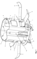
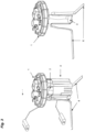
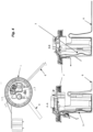
- the base plate (1) illustrated in Figures 3 and 4 is, on the other hand, a base plate intended to seal an orifice in the upper wall of a tank.
- a screw thread (1') visible in the cross sections from Figure 4 ) able to cooperate with a complementary screw thread on an excrescence of the tank.
- This base plate (1) also incorporates a support (4) for a flexible heater (2) acting as a urea trap.
- This support (4) is attached to the base plate (as can be seen in the cross sections from Figure 4 ) and is pinned to the bottom of the tank by at least one spring (not represented).
- the flexibility of the heater (2) enables it to adapt to the various compression ratios of the spring that depend on the distance between the top and bottom of the tank.
Landscapes
- Engineering & Computer Science (AREA)
- Chemical & Material Sciences (AREA)
- Chemical Kinetics & Catalysis (AREA)
- Mechanical Engineering (AREA)
- Combustion & Propulsion (AREA)
- General Engineering & Computer Science (AREA)
- Health & Medical Sciences (AREA)
- Toxicology (AREA)
- Physics & Mathematics (AREA)
- Thermal Sciences (AREA)
- Transportation (AREA)
- Exhaust Gas After Treatment (AREA)
- Exhaust Gas Treatment By Means Of Catalyst (AREA)
- Physical Or Chemical Processes And Apparatus (AREA)
- Resistance Heating (AREA)
Claims (14)
- Harnstofftank mit einem integrierten Erwärmungselement, wobei das Erwärmungselement mindestens einen flexiblen Heizungsteil umfasst, der eine flexible Heizung (2) ist, die mindestens eine Widerstandsbahn umfasst, die an einem flexiblen Film befestigt und/oder zwischen zwei flexiblen Filmen angeordnet ist, wobei die flexible Heizung mit mindestens einem Tentakel ausgestattet ist, der mindestens einen Teil der Widerstandsbahn umfasst.
- Tank nach Anspruch 1, dadurch gekennzeichnet, dass die flexible Heizung (2) mehrere Widerstandsbahnen umfasst, die parallel geschaltet sind.
- Tank nach einem der vorstehenden Ansprüche, wobei die flexible Heizung (2) eine oder mehrere Edelstahlwiderstandsbahn(en) umfasst, die zwischen zwei Silikonharzfilmen eingelegt sind, von denen einer mit einem Netz aus Glasfasern bedeckt ist.
- Tank nach einem der vorstehenden Ansprüche, dadurch gekennzeichnet, dass die flexible Heizung (2) einen variablen Leistungsverlust pro Flächeneinheit der Widerstandsbahn aufweist.
- Tank nach einem der vorstehenden Ansprüche, dadurch gekennzeichnet, dass die flexible Heizung (2) an einem Träger befestigt ist, der in eine Grundplatte (1) integriert ist, die mindestens ein aktives Zubehör des Tanks und/oder eines Harnstoffeinspritzsystems integriert.
- Tank nach dem vorstehenden Anspruch, dadurch gekennzeichnet, dass der Träger eine im Wesentlichen zylindrische Form aufweist und sich im Wesentlichen über die gesamte Höhe des Tanks erstreckt.
- Tank nach dem vorstehenden Anspruch, dadurch gekennzeichnet, dass die Heizung (2) mindestens eine flexible Lasche (8) umfasst, die mit mindestens einem Teil der Widerstandsbahn ausgestattet ist, die dauerhaft in Kontakt mit der oberen Wand des Tanks steht.
- Tank nach einem der Ansprüche 5 bis 7, wobei der Träger ein Volumen abgrenzt, innerhalb dessen mindestens ein Teil der flexiblen Heizung (2) befestigt ist.
- Tank nach einem der vorstehenden Ansprüche, wobei mindestens ein Tentakel (6, 6') ein freies Ende aufweist, das fest an einem Schwimmer befestigt ist, der es zwingt, in der flüssigen Phase zu bleiben.
- Tank nach Anspruch 1 oder 9, wobei mindestens ein Tentakel (6') so bemessen ist, dass es in ein Rohr eingeführt werden kann, und wobei dieses Tentakel ein freies Ende umfasst, das mit einer Öffnung versehen ist.
- Tank nach einem der Ansprüche 1, 6, 9 oder 10, wobei mindestens ein Tentakel (6, 6') sich zumindest teilweise in eine Füllschnittstelle des Tanks erstreckt.
- Tank nach einem der vorstehenden Ansprüche, dadurch gekennzeichnet, dass er einen Filter umfasst, der mit einer Leitung verbunden ist, innerhalb derer ein Teil der flexiblen Heizung (2) eingeführt wird, wobei der Filter durch eine undurchlässige mechanische Befestigung, die eine Dichtung einschließt, damit verbunden ist.
- Tank nach einem der vorstehenden Ansprüche, wobei die Heizung (2) mindestens 2 Bahnen umfasst, die parallel geschaltet werden können, um eine kapazitive Messvorrichtung zu bilden, die es möglich macht, den Harnstoffpegel im Tank zu messen.
- Grundplatte (1), geeignet für einen Tank nach einem der vorstehenden Ansprüche, die mindestens ein aktives Zubehör eines Harnstofflagersystems und/oder -einspritzsystems und auch mindestens ein Erwärmungselement integriert, das mindestens einen flexiblen Teil aufweist, dadurch gekennzeichnet, dass das Erwärmungselement eine flexible Heizung (2) ist, die mindestens eine Widerstandsbahn umfasst, die an einem flexiblen Film befestigt und/oder zwischen zwei flexiblen Filmen angeordnet ist, und die:- mehrere Widerstandsbahnen umfasst, die parallel geschaltet sind; und/oder- mit Tentakeln ausgestattet ist, von denen einige sich in den Tank erstrecken können und andere mit Öffnungen ausgestattet sind, die es ihnen ermöglichen, leichter in eine Leitung oder ein Zuleitungsrohr eingesetzt zu werden; und/oder- an einem Träger befestigt ist, der in der Lage ist, als ein Kraftstoffabscheider und/oder ein Konvektionskasten zu fungieren.
Priority Applications (2)
| Application Number | Priority Date | Filing Date | Title |
|---|---|---|---|
| EP17197580.8A EP3301272B1 (de) | 2007-05-16 | 2008-05-15 | Harnstofftank und grundplatte mit integriertem erwärmungselement |
| PL17197580T PL3301272T3 (pl) | 2007-05-16 | 2008-05-15 | Zbiornik mocznika i płyta denna z wbudowanym elementem grzejnym |
Applications Claiming Priority (3)
| Application Number | Priority Date | Filing Date | Title |
|---|---|---|---|
| FR0755118A FR2916188B1 (fr) | 2007-05-16 | 2007-05-16 | Reservoir a uree et embase avec element chauffant integre. |
| FR0756635A FR2918968A3 (fr) | 2007-05-16 | 2007-07-20 | Reservoir a uree et embase avec element chauffant integre. |
| PCT/EP2008/055936 WO2008138960A1 (en) | 2007-05-16 | 2008-05-15 | Urea tank and base plate with an integrated heating element |
Related Child Applications (2)
| Application Number | Title | Priority Date | Filing Date |
|---|---|---|---|
| EP17197580.8A Division EP3301272B1 (de) | 2007-05-16 | 2008-05-15 | Harnstofftank und grundplatte mit integriertem erwärmungselement |
| EP17197580.8A Division-Into EP3301272B1 (de) | 2007-05-16 | 2008-05-15 | Harnstofftank und grundplatte mit integriertem erwärmungselement |
Publications (3)
| Publication Number | Publication Date |
|---|---|
| EP2156025A1 EP2156025A1 (de) | 2010-02-24 |
| EP2156025B1 EP2156025B1 (de) | 2020-03-18 |
| EP2156025B2 true EP2156025B2 (de) | 2025-02-26 |
Family
ID=39525384
Family Applications (2)
| Application Number | Title | Priority Date | Filing Date |
|---|---|---|---|
| EP08759611.0A Active EP2156025B2 (de) | 2007-05-16 | 2008-05-15 | Harnstofftank und grundplatte mit integriertem erwärmungselement |
| EP17197580.8A Active EP3301272B1 (de) | 2007-05-16 | 2008-05-15 | Harnstofftank und grundplatte mit integriertem erwärmungselement |
Family Applications After (1)
| Application Number | Title | Priority Date | Filing Date |
|---|---|---|---|
| EP17197580.8A Active EP3301272B1 (de) | 2007-05-16 | 2008-05-15 | Harnstofftank und grundplatte mit integriertem erwärmungselement |
Country Status (8)
| Country | Link |
|---|---|
| US (3) | US8625978B2 (de) |
| EP (2) | EP2156025B2 (de) |
| JP (2) | JP5749008B2 (de) |
| KR (2) | KR101540125B1 (de) |
| CN (1) | CN101680343B (de) |
| FR (2) | FR2916188B1 (de) |
| PL (1) | PL3301272T3 (de) |
| WO (1) | WO2008138960A1 (de) |
Families Citing this family (67)
| Publication number | Priority date | Publication date | Assignee | Title |
|---|---|---|---|---|
| FR2918576B1 (fr) | 2007-07-10 | 2009-10-09 | Inergy Automotive Systems Res | Systeme d'alimentation d'un liquide pour vehicule et module pompe/filtre integre. |
| FR2918718B1 (fr) * | 2007-07-10 | 2013-06-28 | Inergy Automotive Systems Res | Pompe rotative pour vehicule. |
| FR2921911A1 (fr) | 2007-09-21 | 2009-04-10 | Inergy Automotive Systems Res | Systeme de stockage et d'injection d'une solution d'additif dans des gaz d'echappement d'un moteur. |
| FR2926542A1 (fr) | 2008-01-17 | 2009-07-24 | Inergy Automotive Systems Res | Procede pour le transfert d'un liquide au moyen d'une pompe |
| DE112009001331T5 (de) | 2008-06-03 | 2011-04-28 | Inergy Automotive Systems Research (S.A.) | Prozess zum Starten eines SCR-Systems |
| US8359831B2 (en) | 2008-10-31 | 2013-01-29 | Ti Group Automotive Systems, L.L.C. | Reactant delivery for engine exhaust gas treatment |
| US20100146940A1 (en) * | 2008-12-17 | 2010-06-17 | Delphi Technologies, Inc. | Active buoyant urea heater |
| FR2943744A1 (fr) * | 2009-03-24 | 2010-10-01 | Inergy Automotive Systems Res | Pompe rotative |
| FR2954404A1 (fr) * | 2009-12-22 | 2011-06-24 | Ti Automotive Fuel Systems Sas | Crepine chauffante et dispositif d'injection comprenant une telle crepine |
| KR101765969B1 (ko) * | 2009-12-24 | 2017-08-08 | 플라스틱 옴니엄 어드벤스드 이노베이션 앤드 리서치 | 자체 조절형 가열 부재가 설치된 저장용기 및 탱크 |
| EP2341224B1 (de) * | 2009-12-24 | 2017-06-14 | DBK David + Baader GmbH | Schmelztank, Heizmodul und Tanksystem |
| EP2339138A1 (de) * | 2009-12-24 | 2011-06-29 | Inergy Automotive Systems Research (Société Anonyme) | Mit einem Heizelement ausgerüsteter Flansch |
| DE102010004612A1 (de) * | 2010-01-13 | 2011-07-14 | Emitec Gesellschaft für Emissionstechnologie mbH, 53797 | Vorrichtung mit einem Tank und einer Fördereinheit für Reduktionsmittel |
| DE102010009182B4 (de) | 2010-02-01 | 2018-10-04 | Eichenauer Heizelemente Gmbh & Co. Kg | Heizvorrichtung |
| DE102010010528A1 (de) * | 2010-03-05 | 2011-09-08 | Emitec Gesellschaft Für Emissionstechnologie Mbh | Vorrichtung zur Bereitstellung eines flüssigen Reduktionsmittels |
| EP2375854B1 (de) | 2010-04-06 | 2015-12-02 | Plastic Omnium Advanced Innovation and Research | Heizvorrichtung für einen Fahrzeugflüssigkeitstank, Kraftfahrzeug damit und Verfahren zum Heizen des Fahrzeugflüssigkeitstanks |
| FR2959497B1 (fr) | 2010-05-03 | 2014-01-10 | Coutier Moulage Gen Ind | Reservoir de fluide avec bol de reserve chauffant |
| BR112012031838B1 (pt) | 2010-06-15 | 2020-12-08 | Shaw Development, Llc | combinação e unidade de cabeçote |
| US8822887B2 (en) | 2010-10-27 | 2014-09-02 | Shaw Arrow Development, LLC | Multi-mode heater for a diesel emission fluid tank |
| CN103250464B (zh) * | 2010-11-04 | 2016-08-31 | 英瑞杰汽车系统研究公司 | 用于制造柔性加热器的方法 |
| FR2967723B1 (fr) | 2010-11-24 | 2015-11-13 | Inergy Automotive Systems Res | Reservoir de stockage pour additif de gaz d'echappement d'un moteur |
| SE535474C2 (sv) * | 2010-12-02 | 2012-08-21 | Scania Cv Ab | Reduktionsmedelslagringssystem med uppvärmningsanordning |
| DE202010016319U1 (de) * | 2010-12-04 | 2012-03-19 | Reutter Gmbh | Einsatz für einen Einfüllstutzen eines Harnstoffbehälters |
| DE102010053737A1 (de) * | 2010-12-08 | 2012-06-14 | Voss Automotive Gmbh | Beheizbare Fluidleitung, deren Verwendung sowie Verfahren zu ihrer Herstellung |
| EP2655822B1 (de) * | 2010-12-23 | 2018-10-10 | Plastic Omnium Advanced Innovation and Research | Speichersystem für motorabgaszusatz |
| DE102011006105A1 (de) * | 2011-03-25 | 2012-09-27 | Robert Bosch Gmbh | Funktionseinheit für einen Reduktionsmittel-Vorratstank sowie Reduktionsmittel-Vorratstank |
| CN103635666B (zh) | 2011-07-07 | 2016-03-30 | 贝卡尔特公司 | 具有加热元件的选择性催化还原罐 |
| EP2549072A1 (de) | 2011-07-20 | 2013-01-23 | Inergy Automotive Systems Research (Société Anonyme) | Flüssigkeitseinspritzsystem für Fahrzeuge, Regler und Verfahren zum Aufwärmen dieses Flüssigkeitseinspritzsystems |
| ITTO20110707A1 (it) * | 2011-07-29 | 2011-10-28 | Errecinque S R L | Dispositivo riscaldatore per una soluzione di acqua e urea per veicoli |
| EP2574599A1 (de) * | 2011-09-30 | 2013-04-03 | Inergy Automotive Systems Research (Société Anonyme) | Behälter für die Speicherung von Ammoniak durch Sorption |
| DE102012204106A1 (de) * | 2012-03-15 | 2013-09-19 | Robert Bosch Gmbh | Wärmeverteilkörper für eine Heizung eines SCR-Systems und Heizung |
| EP2650497A1 (de) * | 2012-04-11 | 2013-10-16 | TI Automotive Fuel Systems SAS | System zur Aufbewahrung einer Additivlösung für einen Fahrzeugmotor |
| DE102012109675A1 (de) | 2012-10-11 | 2014-04-30 | Emitec Denmark A/S | Vorrichtung zur Bereitstellung eines flüssigen Additivs |
| US8973778B2 (en) * | 2012-10-29 | 2015-03-10 | Ti Automotive Technology Center Gmbh | Self-adjusting connector |
| KR101487332B1 (ko) * | 2013-03-25 | 2015-01-28 | 지금강 주식회사 | 동결방지 기능이 있는 우레아 탱크 |
| CN105431618B (zh) | 2013-06-13 | 2019-01-11 | 大陆汽车有限责任公司 | 用于计量供给液体的模块 |
| EP2848931A1 (de) * | 2013-09-16 | 2015-03-18 | Inergy Automotive Systems Research (Société Anonyme) | Fahrzeugharnstofftank in Verbindung mit einer Messkammer zur akustischen Qualitäts- und Füllstandskontrolle |
| US9809380B2 (en) | 2013-12-12 | 2017-11-07 | Savannah River Nuclear Solutions, Llc | Heat transfer unit and method for prefabricated vessel |
| US9957103B2 (en) | 2013-12-12 | 2018-05-01 | Savannah River Nuclear Solutions, Llc | Heat transfer unit and method for prefabricated vessel |
| FR3014704B1 (fr) | 2013-12-12 | 2017-04-28 | Delphi Tech Holding S A R L | Dispositif de declenchement d’un signal electrique pour filtre a solution aqueuse |
| USD729141S1 (en) | 2014-05-28 | 2015-05-12 | Shaw Development LLC | Diesel emissions fluid tank |
| USD729722S1 (en) | 2014-05-28 | 2015-05-19 | Shaw Development LLC | Diesel emissions fluid tank floor |
| DE102014211251A1 (de) * | 2014-06-12 | 2015-12-17 | Robert Bosch Gmbh | Versorgungsmodul für ein Abgasnachbehandlungssystem |
| WO2016001178A1 (de) * | 2014-07-02 | 2016-01-07 | Arte Reverse Engineering Gbr | Heizeinrichtung für eine vorrichtung zur aufnahme und bereitstellung von flüssigem reduktionsmittel |
| DE102014015714B4 (de) | 2014-07-02 | 2026-02-05 | ARTE Reverse Engineering GbR (vertretungsberechtigte Gesellschafter Alexander Reinisch, 98617 Vachdorf; Heiko Lantzsch, 99817 Eisenach) | Heizeinrichtung für eine Vorrichtung zur Aufnahme und Bereitstellung von flüssigem Reduktionsmittel |
| DE102014223517A1 (de) | 2014-11-18 | 2016-05-19 | Röchling Automotive SE & Co. KG | Beheizbarer Kraftfahrzeugbetriebsflüssigkeitstank und Verfahren zur Herstellung der Heizeinrichtung für diesen |
| CN106150619B (zh) * | 2015-04-01 | 2023-09-15 | 天纳克(苏州)排放系统有限公司 | 尿素喷射组件 |
| LU92720B1 (en) | 2015-05-12 | 2016-11-14 | Iee Int Electronics & Eng Sa | Heater device for failsafe warming up of temperature-critical materials |
| DE102015212919A1 (de) * | 2015-07-10 | 2017-01-12 | Robert Bosch Gmbh | Tankeinrichtung für ein Abgasnachbehandlungssystem, Abgasnachbehandlungssystem |
| ITUB20154867A1 (it) * | 2015-11-06 | 2017-05-06 | Eltek Spa | Dispositivo riscaldatore elettrico, particolarmente per veicoli |
| DE102016203495A1 (de) | 2016-03-03 | 2017-09-07 | Röchling Automotive SE & Co. KG | Heizeinrichtung und Tank mit Heizeinrichtung |
| US10207913B2 (en) * | 2016-06-09 | 2019-02-19 | Hyundai Motor Company | Fuel-urea injection apparatus including common inlet for vehicle |
| FR3052821B1 (fr) | 2016-06-20 | 2018-06-22 | Sonceboz Automotive Sa | Pompe a fluide motorisee a rechauffement ameliore |
| DE102017205143A1 (de) | 2016-06-28 | 2017-12-28 | Bayerische Motoren Werke Aktiengesellschaft | Vorrichtung zur Bereitstellung einer gefriergefährdeten Flüssigkeit, insbesondere einer wässrigen Harnstofflösung |
| DE212017000186U1 (de) | 2016-07-18 | 2019-05-08 | Plastic Omnium Advanced Innovation And Research | Harnstofftank mit Heizelement und Profil |
| US10323556B2 (en) * | 2016-12-16 | 2019-06-18 | Gates Corporation | Electric immersion heater for diesel exhaust fluid reservoir |
| DE102017203283A1 (de) * | 2017-03-01 | 2018-09-06 | Robert Bosch Gmbh | Heizeinrichtung |
| DK179836B1 (en) * | 2018-01-18 | 2019-07-29 | Waturu Holding Aps | Device for treating and heating water in tank style water heaters |
| US11623881B2 (en) | 2018-03-19 | 2023-04-11 | Plastic Omnium Advanced Innovation And Research | Vehicle system for injecting an aqueous solution in the combustion chamber of the internal combustion engine and method for injecting an aqueous solution in the combustion chamber of the internal combustion |
| DE102018208643A1 (de) * | 2018-05-30 | 2019-12-05 | Röchling Automotive SE & Co. KG | Kfz-Tankbaugruppe und Entnahmemodul mit einem porösen Förderkörper |
| US10859208B2 (en) | 2018-05-31 | 2020-12-08 | Savannah River Nuclear Solutions, Llc | Heat transfer unit for prefabricated vessel |
| IT201800007346A1 (it) * | 2018-07-19 | 2020-01-19 | Riscaldatore elettrico per serbatoio | |
| EP3598846A1 (de) * | 2018-07-19 | 2020-01-22 | Magna Steyr Fuel Systems GesmbH | Heizmodul |
| DE102018132119A1 (de) | 2018-12-13 | 2020-06-18 | Veritas Ag | Fahrzeugflüssigkeitstank mit einer Oberflächen-modifizierenden Substanz |
| FR3096738B1 (fr) | 2019-05-31 | 2021-05-28 | Plastic Omnium Advanced Innovation & Res | Dispositif de fixation pour module de distribution de solution aqueuse contenue dans un réservoir à bord d’un véhicule automobile |
| CN112477588B (zh) * | 2020-12-14 | 2022-02-25 | 山东鸿硕橡塑制品有限公司 | 一种油动储热式防冷凝型汽车油箱 |
| CN117563445A (zh) * | 2023-12-29 | 2024-02-20 | 青海省化工设计研究院有限公司 | 一种车用尿素溶液制备、存储及加注的一体化撬装设备 |
Citations (3)
| Publication number | Priority date | Publication date | Assignee | Title |
|---|---|---|---|---|
| WO1988010058A1 (fr) † | 1987-06-01 | 1988-12-15 | Beauferey Jean Francois | Element chauffant souple et son procede de fabrication |
| US5155800A (en) † | 1991-02-27 | 1992-10-13 | Process Technology Inc. | Panel heater assembly for use in a corrosive environment and method of manufacturing the heater |
| EP1473447A1 (de) † | 2003-04-29 | 2004-11-03 | MAN Nutzfahrzeuge Aktiengesellschaft | Flüssigkeitsbehälter für Kraftfahrzeuge, insbesondere für eine wässrige Harnstofflösung |
Family Cites Families (34)
| Publication number | Priority date | Publication date | Assignee | Title |
|---|---|---|---|---|
| US600285A (en) * | 1898-03-08 | holland | ||
| US2613311A (en) * | 1950-01-25 | 1952-10-07 | Miller Mfg Company Inc | Electrical heating device for poultry watering bowls |
| US3803386A (en) * | 1972-10-13 | 1974-04-09 | Kerdon Corp | Aquarium heater |
| US3890486A (en) * | 1973-05-01 | 1975-06-17 | Equipment Dev Corp | Aquarium-tank heating control |
| US3973102A (en) * | 1976-01-12 | 1976-08-03 | Equipment Development Corporation | Heating and temperature control device for a bath-liquid |
| JPS5369835U (de) | 1976-11-15 | 1978-06-12 | ||
| IT213900Z2 (it) | 1988-03-18 | 1990-03-01 | Bravo Spa | Apparato di riscaldamento a vasca perfezionato. |
| US4889973A (en) * | 1988-10-12 | 1989-12-26 | Farinacci Michael F | Aquarium heater |
| US5448037A (en) * | 1992-08-03 | 1995-09-05 | Mitsui Toatsu Chemicals, Inc. | Transparent panel heater and method for manufacturing same |
| GB2285729B (en) * | 1993-12-24 | 1997-10-22 | British Tech Group Int | Electrically conductive resistance heater |
| DE19634671C2 (de) | 1996-08-28 | 1998-08-27 | Stahl R Schaltgeraete Gmbh | Metallgehäuse in der Zündschutzart "Druckfeste Kapselung" |
| US6063350A (en) * | 1997-04-02 | 2000-05-16 | Clean Diesel Technologies, Inc. | Reducing nox emissions from an engine by temperature-controlled urea injection for selective catalytic reduction |
| DE19834671C1 (de) | 1998-07-31 | 2000-02-24 | Siemens Ag | Verfahren und Vorrichtung zum Betanken eines Kraftfahrzeuges |
| ES2191386T3 (es) * | 1998-07-31 | 2003-09-01 | Siemens Ag | Dispositivo para llenar contenedores. |
| CN2396199Y (zh) * | 1999-11-04 | 2000-09-13 | 魏鑫 | 内燃机车节油型尾气净化器 |
| US6649886B1 (en) * | 2002-05-11 | 2003-11-18 | David Kleshchik | Electric heating cloth and method |
| US6363771B1 (en) * | 1999-11-24 | 2002-04-02 | Caterpillar Inc. | Emissions diagnostic system |
| DE20219608U1 (de) * | 2002-12-05 | 2003-06-12 | Erhard & Söhne GmbH, 73525 Schwäbisch Gmünd | Behälter zur Aufnahme von Betriebsstoffen |
| JP2005155536A (ja) | 2003-11-27 | 2005-06-16 | Japan Aerospace Exploration Agency | 温度制御型アンモニア水・ガス供給装置 |
| JP4137831B2 (ja) | 2004-03-29 | 2008-08-20 | 日産ディーゼル工業株式会社 | エンジンの排気浄化装置 |
| ATE314572T1 (de) * | 2004-03-29 | 2006-01-15 | Dbk David & Baader Gmbh | Entnahmeeinheit mit heizeinrichtung und wärmetauscherfortsatz, für einen tank mit ausfällendem und/oder gefrierendem fluid |
| JP4431482B2 (ja) | 2004-11-16 | 2010-03-17 | 日野自動車株式会社 | 尿素水貯蔵装置 |
| FR2879238B1 (fr) | 2004-12-14 | 2010-02-19 | Inergy Automotive Systems Res | Procede et systeme de stockage et d'injection d'un additif dans des gaz d'echappement d'un moteur |
| DE102004062605B4 (de) * | 2004-12-24 | 2013-02-28 | Eichenauer Heizelemente Gmbh & Co. Kg | Elektrische Heizeinrichtung zum Erwärmen von Flüssigkeit in einem Kraftfahrzeug und Flüssigkeitsbehälter mit einer derartigen Heizeinrichtung |
| WO2006131201A2 (de) * | 2005-06-04 | 2006-12-14 | Eichenauer Heizelemente Gmbh & Co.Kg | Harnstoffversorgungssystem für einen abgasreinigungskatalysator und hierfür geeigneter heizeinsatz |
| JP4594278B2 (ja) | 2005-07-08 | 2010-12-08 | 日本特殊陶業株式会社 | 液体状態検知センサ |
| EP1742042B1 (de) | 2005-07-08 | 2011-11-23 | Ngk Spark Plug Co., Ltd | Sensor zur Detektion von Flüssigkeitszuständen |
| DE102005037201A1 (de) * | 2005-08-06 | 2007-02-22 | Eichenauer Heizelemente Gmbh & Co. Kg | Heizsystem |
| DE202007019679U1 (de) * | 2006-06-08 | 2015-07-27 | Inergy Automotive Systems Research (S.A.) | System zur Lagerung von Motorabgasadditiven |
| FR2905161B1 (fr) | 2006-08-25 | 2012-04-20 | Inergy Automotive Systems Res | Raccord avec element chauffant integre. |
| DE102006046899A1 (de) * | 2006-10-04 | 2008-04-10 | Robert Bosch Gmbh | Tank zur Bevorratung eines Reduktionsmittels |
| US7268325B1 (en) * | 2006-10-23 | 2007-09-11 | Linkwin Technology Co., Ltd. | Method of making flexible sheet heater |
| US8206656B2 (en) * | 2008-07-30 | 2012-06-26 | Ford Global Technologies, Llc | Freezable-liquid dispenser for motor vehicles |
| DE102009040930B4 (de) * | 2009-09-11 | 2013-01-03 | Elkamet Kunststofftechnik Gmbh | Heizbarer Flüssigkeitsbehälter aus Kunststoffmaterial und Verfahren zu seiner Herstellung |
-
2007
- 2007-05-16 FR FR0755118A patent/FR2916188B1/fr active Active
- 2007-07-20 FR FR0756635A patent/FR2918968A3/fr active Pending
-
2008
- 2008-05-15 JP JP2010507918A patent/JP5749008B2/ja active Active
- 2008-05-15 US US12/599,478 patent/US8625978B2/en active Active
- 2008-05-15 CN CN2008800186041A patent/CN101680343B/zh active Active
- 2008-05-15 PL PL17197580T patent/PL3301272T3/pl unknown
- 2008-05-15 EP EP08759611.0A patent/EP2156025B2/de active Active
- 2008-05-15 EP EP17197580.8A patent/EP3301272B1/de active Active
- 2008-05-15 KR KR1020097026133A patent/KR101540125B1/ko active Active
- 2008-05-15 KR KR1020157007014A patent/KR20150038703A/ko not_active Ceased
- 2008-05-15 WO PCT/EP2008/055936 patent/WO2008138960A1/en not_active Ceased
-
2013
- 2013-12-06 US US14/099,080 patent/US9273584B2/en active Active
-
2015
- 2015-02-05 JP JP2015021034A patent/JP2015110950A/ja active Pending
-
2016
- 2016-02-04 US US15/016,030 patent/US10139130B2/en active Active
Patent Citations (3)
| Publication number | Priority date | Publication date | Assignee | Title |
|---|---|---|---|---|
| WO1988010058A1 (fr) † | 1987-06-01 | 1988-12-15 | Beauferey Jean Francois | Element chauffant souple et son procede de fabrication |
| US5155800A (en) † | 1991-02-27 | 1992-10-13 | Process Technology Inc. | Panel heater assembly for use in a corrosive environment and method of manufacturing the heater |
| EP1473447A1 (de) † | 2003-04-29 | 2004-11-03 | MAN Nutzfahrzeuge Aktiengesellschaft | Flüssigkeitsbehälter für Kraftfahrzeuge, insbesondere für eine wässrige Harnstofflösung |
Non-Patent Citations (1)
| Title |
|---|
| ANONYMOUS: "Thermofoil™ Heaters", MINCO PRODUCTS INC., BULLETIN HS -202 (D), 22 July 2004 (2004-07-22), pages A - L-5 † |
Also Published As
| Publication number | Publication date |
|---|---|
| WO2008138960A1 (en) | 2008-11-20 |
| US10139130B2 (en) | 2018-11-27 |
| FR2916188A1 (fr) | 2008-11-21 |
| EP3301272A1 (de) | 2018-04-04 |
| US9273584B2 (en) | 2016-03-01 |
| WO2008138960A8 (en) | 2010-06-17 |
| JP2015110950A (ja) | 2015-06-18 |
| JP2010526740A (ja) | 2010-08-05 |
| US20140093226A1 (en) | 2014-04-03 |
| KR20100024937A (ko) | 2010-03-08 |
| FR2916188B1 (fr) | 2011-05-06 |
| KR20150038703A (ko) | 2015-04-08 |
| CN101680343A (zh) | 2010-03-24 |
| EP3301272B1 (de) | 2019-05-01 |
| US20100220984A1 (en) | 2010-09-02 |
| PL3301272T3 (pl) | 2019-10-31 |
| JP5749008B2 (ja) | 2015-07-15 |
| FR2918968A1 (fr) | 2009-01-23 |
| US20160195300A1 (en) | 2016-07-07 |
| CN101680343B (zh) | 2013-06-19 |
| US8625978B2 (en) | 2014-01-07 |
| EP2156025A1 (de) | 2010-02-24 |
| EP2156025B1 (de) | 2020-03-18 |
| KR101540125B1 (ko) | 2015-07-28 |
| FR2918968A3 (fr) | 2009-01-23 |
Similar Documents
| Publication | Publication Date | Title |
|---|---|---|
| EP2156025B2 (de) | Harnstofftank und grundplatte mit integriertem erwärmungselement | |
| KR101536011B1 (ko) | 통합된 가열 요소를 가진 커플링이 구비된 유레아 라인 | |
| US9677446B2 (en) | Engine exhaust gas additive storage system | |
| CN101460715B (zh) | 发动机排气添加剂存储系统 | |
| JP6391720B2 (ja) | エンジン排出ガス添加剤貯蔵システム |
Legal Events
| Date | Code | Title | Description |
|---|---|---|---|
| PUAI | Public reference made under article 153(3) epc to a published international application that has entered the european phase |
Free format text: ORIGINAL CODE: 0009012 |
|
| 17P | Request for examination filed |
Effective date: 20091216 |
|
| AK | Designated contracting states |
Kind code of ref document: A1 Designated state(s): AT BE BG CH CY CZ DE DK EE ES FI FR GB GR HR HU IE IS IT LI LT LU LV MC MT NL NO PL PT RO SE SI SK TR |
|
| AX | Request for extension of the european patent |
Extension state: AL BA MK RS |
|
| DAX | Request for extension of the european patent (deleted) | ||
| 17Q | First examination report despatched |
Effective date: 20140224 |
|
| TPAC | Observations filed by third parties |
Free format text: ORIGINAL CODE: EPIDOSNTIPA |
|
| RBV | Designated contracting states (corrected) |
Designated state(s): AT BE BG CH CY CZ DE DK EE ES FI GB GR HR HU IE IS IT LI LT LU LV MC MT NL NO PL PT RO SE SI SK TR |
|
| RAP1 | Party data changed (applicant data changed or rights of an application transferred) |
Owner name: PLASTIC OMNIUM ADVANCED INNOVATION AND RESEARCH |
|
| STAA | Information on the status of an ep patent application or granted ep patent |
Free format text: STATUS: EXAMINATION IS IN PROGRESS |
|
| GRAP | Despatch of communication of intention to grant a patent |
Free format text: ORIGINAL CODE: EPIDOSNIGR1 |
|
| STAA | Information on the status of an ep patent application or granted ep patent |
Free format text: STATUS: GRANT OF PATENT IS INTENDED |
|
| INTG | Intention to grant announced |
Effective date: 20180920 |
|
| GRAJ | Information related to disapproval of communication of intention to grant by the applicant or resumption of examination proceedings by the epo deleted |
Free format text: ORIGINAL CODE: EPIDOSDIGR1 |
|
| STAA | Information on the status of an ep patent application or granted ep patent |
Free format text: STATUS: EXAMINATION IS IN PROGRESS |
|
| INTC | Intention to grant announced (deleted) | ||
| RAP1 | Party data changed (applicant data changed or rights of an application transferred) |
Owner name: PLASTIC OMNIUM ADVANCED INNOVATION AND RESEARCH |
|
| GRAS | Grant fee paid |
Free format text: ORIGINAL CODE: EPIDOSNIGR3 |
|
| STAA | Information on the status of an ep patent application or granted ep patent |
Free format text: STATUS: GRANT OF PATENT IS INTENDED |
|
| GRAP | Despatch of communication of intention to grant a patent |
Free format text: ORIGINAL CODE: EPIDOSNIGR1 |
|
| INTG | Intention to grant announced |
Effective date: 20200108 |
|
| GRAA | (expected) grant |
Free format text: ORIGINAL CODE: 0009210 |
|
| STAA | Information on the status of an ep patent application or granted ep patent |
Free format text: STATUS: THE PATENT HAS BEEN GRANTED |
|
| AK | Designated contracting states |
Kind code of ref document: B1 Designated state(s): AT BE BG CH CY CZ DE DK EE ES FI GB GR HR HU IE IS IT LI LT LU LV MC MT NL NO PL PT RO SE SI SK TR |
|
| REG | Reference to a national code |
Ref country code: GB Ref legal event code: FG4D |
|
| REG | Reference to a national code |
Ref country code: DE Ref legal event code: R096 Ref document number: 602008062334 Country of ref document: DE |
|
| REG | Reference to a national code |
Ref country code: AT Ref legal event code: REF Ref document number: 1246140 Country of ref document: AT Kind code of ref document: T Effective date: 20200415 Ref country code: IE Ref legal event code: FG4D |
|
| REG | Reference to a national code |
Ref country code: RO Ref legal event code: EPE |
|
| PG25 | Lapsed in a contracting state [announced via postgrant information from national office to epo] |
Ref country code: NO Free format text: LAPSE BECAUSE OF FAILURE TO SUBMIT A TRANSLATION OF THE DESCRIPTION OR TO PAY THE FEE WITHIN THE PRESCRIBED TIME-LIMIT Effective date: 20200618 Ref country code: FI Free format text: LAPSE BECAUSE OF FAILURE TO SUBMIT A TRANSLATION OF THE DESCRIPTION OR TO PAY THE FEE WITHIN THE PRESCRIBED TIME-LIMIT Effective date: 20200318 |
|
| REG | Reference to a national code |
Ref country code: NL Ref legal event code: MP Effective date: 20200318 |
|
| PG25 | Lapsed in a contracting state [announced via postgrant information from national office to epo] |
Ref country code: BG Free format text: LAPSE BECAUSE OF FAILURE TO SUBMIT A TRANSLATION OF THE DESCRIPTION OR TO PAY THE FEE WITHIN THE PRESCRIBED TIME-LIMIT Effective date: 20200618 Ref country code: GR Free format text: LAPSE BECAUSE OF FAILURE TO SUBMIT A TRANSLATION OF THE DESCRIPTION OR TO PAY THE FEE WITHIN THE PRESCRIBED TIME-LIMIT Effective date: 20200619 Ref country code: SE Free format text: LAPSE BECAUSE OF FAILURE TO SUBMIT A TRANSLATION OF THE DESCRIPTION OR TO PAY THE FEE WITHIN THE PRESCRIBED TIME-LIMIT Effective date: 20200318 Ref country code: LV Free format text: LAPSE BECAUSE OF FAILURE TO SUBMIT A TRANSLATION OF THE DESCRIPTION OR TO PAY THE FEE WITHIN THE PRESCRIBED TIME-LIMIT Effective date: 20200318 Ref country code: HR Free format text: LAPSE BECAUSE OF FAILURE TO SUBMIT A TRANSLATION OF THE DESCRIPTION OR TO PAY THE FEE WITHIN THE PRESCRIBED TIME-LIMIT Effective date: 20200318 |
|
| REG | Reference to a national code |
Ref country code: LT Ref legal event code: MG4D |
|
| PG25 | Lapsed in a contracting state [announced via postgrant information from national office to epo] |
Ref country code: NL Free format text: LAPSE BECAUSE OF FAILURE TO SUBMIT A TRANSLATION OF THE DESCRIPTION OR TO PAY THE FEE WITHIN THE PRESCRIBED TIME-LIMIT Effective date: 20200318 |
|
| PG25 | Lapsed in a contracting state [announced via postgrant information from national office to epo] |
Ref country code: PT Free format text: LAPSE BECAUSE OF FAILURE TO SUBMIT A TRANSLATION OF THE DESCRIPTION OR TO PAY THE FEE WITHIN THE PRESCRIBED TIME-LIMIT Effective date: 20200812 Ref country code: LT Free format text: LAPSE BECAUSE OF FAILURE TO SUBMIT A TRANSLATION OF THE DESCRIPTION OR TO PAY THE FEE WITHIN THE PRESCRIBED TIME-LIMIT Effective date: 20200318 Ref country code: IS Free format text: LAPSE BECAUSE OF FAILURE TO SUBMIT A TRANSLATION OF THE DESCRIPTION OR TO PAY THE FEE WITHIN THE PRESCRIBED TIME-LIMIT Effective date: 20200718 Ref country code: SK Free format text: LAPSE BECAUSE OF FAILURE TO SUBMIT A TRANSLATION OF THE DESCRIPTION OR TO PAY THE FEE WITHIN THE PRESCRIBED TIME-LIMIT Effective date: 20200318 Ref country code: CZ Free format text: LAPSE BECAUSE OF FAILURE TO SUBMIT A TRANSLATION OF THE DESCRIPTION OR TO PAY THE FEE WITHIN THE PRESCRIBED TIME-LIMIT Effective date: 20200318 Ref country code: EE Free format text: LAPSE BECAUSE OF FAILURE TO SUBMIT A TRANSLATION OF THE DESCRIPTION OR TO PAY THE FEE WITHIN THE PRESCRIBED TIME-LIMIT Effective date: 20200318 |
|
| REG | Reference to a national code |
Ref country code: AT Ref legal event code: MK05 Ref document number: 1246140 Country of ref document: AT Kind code of ref document: T Effective date: 20200318 |
|
| REG | Reference to a national code |
Ref country code: DE Ref legal event code: R026 Ref document number: 602008062334 Country of ref document: DE |
|
| PLBI | Opposition filed |
Free format text: ORIGINAL CODE: 0009260 |
|
| PLAX | Notice of opposition and request to file observation + time limit sent |
Free format text: ORIGINAL CODE: EPIDOSNOBS2 |
|
| 26 | Opposition filed |
Opponent name: BESCH, ULRICH Effective date: 20201217 |
|
| PG25 | Lapsed in a contracting state [announced via postgrant information from national office to epo] |
Ref country code: MC Free format text: LAPSE BECAUSE OF FAILURE TO SUBMIT A TRANSLATION OF THE DESCRIPTION OR TO PAY THE FEE WITHIN THE PRESCRIBED TIME-LIMIT Effective date: 20200318 Ref country code: CH Free format text: LAPSE BECAUSE OF NON-PAYMENT OF DUE FEES Effective date: 20200531 Ref country code: LI Free format text: LAPSE BECAUSE OF NON-PAYMENT OF DUE FEES Effective date: 20200531 Ref country code: AT Free format text: LAPSE BECAUSE OF FAILURE TO SUBMIT A TRANSLATION OF THE DESCRIPTION OR TO PAY THE FEE WITHIN THE PRESCRIBED TIME-LIMIT Effective date: 20200318 Ref country code: DK Free format text: LAPSE BECAUSE OF FAILURE TO SUBMIT A TRANSLATION OF THE DESCRIPTION OR TO PAY THE FEE WITHIN THE PRESCRIBED TIME-LIMIT Effective date: 20200318 Ref country code: ES Free format text: LAPSE BECAUSE OF FAILURE TO SUBMIT A TRANSLATION OF THE DESCRIPTION OR TO PAY THE FEE WITHIN THE PRESCRIBED TIME-LIMIT Effective date: 20200318 |
|
| PG25 | Lapsed in a contracting state [announced via postgrant information from national office to epo] |
Ref country code: PL Free format text: LAPSE BECAUSE OF FAILURE TO SUBMIT A TRANSLATION OF THE DESCRIPTION OR TO PAY THE FEE WITHIN THE PRESCRIBED TIME-LIMIT Effective date: 20200318 |
|
| REG | Reference to a national code |
Ref country code: BE Ref legal event code: MM Effective date: 20200531 |
|
| GBPC | Gb: european patent ceased through non-payment of renewal fee |
Effective date: 20200618 |
|
| PG25 | Lapsed in a contracting state [announced via postgrant information from national office to epo] |
Ref country code: LU Free format text: LAPSE BECAUSE OF NON-PAYMENT OF DUE FEES Effective date: 20200515 |
|
| PG25 | Lapsed in a contracting state [announced via postgrant information from national office to epo] |
Ref country code: GB Free format text: LAPSE BECAUSE OF NON-PAYMENT OF DUE FEES Effective date: 20200618 Ref country code: IE Free format text: LAPSE BECAUSE OF NON-PAYMENT OF DUE FEES Effective date: 20200515 |
|
| PLBB | Reply of patent proprietor to notice(s) of opposition received |
Free format text: ORIGINAL CODE: EPIDOSNOBS3 |
|
| PG25 | Lapsed in a contracting state [announced via postgrant information from national office to epo] |
Ref country code: BE Free format text: LAPSE BECAUSE OF NON-PAYMENT OF DUE FEES Effective date: 20200531 Ref country code: SI Free format text: LAPSE BECAUSE OF FAILURE TO SUBMIT A TRANSLATION OF THE DESCRIPTION OR TO PAY THE FEE WITHIN THE PRESCRIBED TIME-LIMIT Effective date: 20200318 |
|
| PG25 | Lapsed in a contracting state [announced via postgrant information from national office to epo] |
Ref country code: TR Free format text: LAPSE BECAUSE OF FAILURE TO SUBMIT A TRANSLATION OF THE DESCRIPTION OR TO PAY THE FEE WITHIN THE PRESCRIBED TIME-LIMIT Effective date: 20200318 Ref country code: MT Free format text: LAPSE BECAUSE OF FAILURE TO SUBMIT A TRANSLATION OF THE DESCRIPTION OR TO PAY THE FEE WITHIN THE PRESCRIBED TIME-LIMIT Effective date: 20200318 Ref country code: CY Free format text: LAPSE BECAUSE OF FAILURE TO SUBMIT A TRANSLATION OF THE DESCRIPTION OR TO PAY THE FEE WITHIN THE PRESCRIBED TIME-LIMIT Effective date: 20200318 |
|
| APBM | Appeal reference recorded |
Free format text: ORIGINAL CODE: EPIDOSNREFNO |
|
| APBP | Date of receipt of notice of appeal recorded |
Free format text: ORIGINAL CODE: EPIDOSNNOA2O |
|
| APAH | Appeal reference modified |
Free format text: ORIGINAL CODE: EPIDOSCREFNO |
|
| PLBP | Opposition withdrawn |
Free format text: ORIGINAL CODE: 0009264 |
|
| APBQ | Date of receipt of statement of grounds of appeal recorded |
Free format text: ORIGINAL CODE: EPIDOSNNOA3O |
|
| P01 | Opt-out of the competence of the unified patent court (upc) registered |
Effective date: 20230515 |
|
| APBU | Appeal procedure closed |
Free format text: ORIGINAL CODE: EPIDOSNNOA9O |
|
| PUAH | Patent maintained in amended form |
Free format text: ORIGINAL CODE: 0009272 |
|
| STAA | Information on the status of an ep patent application or granted ep patent |
Free format text: STATUS: PATENT MAINTAINED AS AMENDED |
|
| 27A | Patent maintained in amended form |
Effective date: 20250226 |
|
| AK | Designated contracting states |
Kind code of ref document: B2 Designated state(s): AT BE BG CH CY CZ DE DK EE ES FI GB GR HR HU IE IS IT LI LT LU LV MC MT NL NO PL PT RO SE SI SK TR |
|
| REG | Reference to a national code |
Ref country code: DE Ref legal event code: R102 Ref document number: 602008062334 Country of ref document: DE |
|
| REG | Reference to a national code |
Ref country code: DE Ref legal event code: R081 Ref document number: 602008062334 Country of ref document: DE Owner name: OPMOBILITY C-POWER BELGIUM RESEARCH, BE Free format text: FORMER OWNER: PLASTIC OMNIUM ADVANCED INNOVATION AND RESEARCH, BRUXELLES, BE |
|
| PGFP | Annual fee paid to national office [announced via postgrant information from national office to epo] |
Ref country code: DE Payment date: 20250521 Year of fee payment: 18 |
|
| PGFP | Annual fee paid to national office [announced via postgrant information from national office to epo] |
Ref country code: IT Payment date: 20250527 Year of fee payment: 18 |
|
| PGFP | Annual fee paid to national office [announced via postgrant information from national office to epo] |
Ref country code: RO Payment date: 20250505 Year of fee payment: 18 |